

IFM Electronic AL1122, AL1121 Operating Instructions Manual
Operating Instructions
IO-Link Master with EtherNet/IP interface
StandardLine
8 Ports
IP 65 / IP 67
AL1122
ifm firmware: 1.1.22 or higher
LR DEVICE: 1.1.0.87 or higher
IO-Link: 1.1.2
English
7391102_00_UK
2017
-05-31

ifm Operating Instructions IO-Link Master with EtherNet/IP interface StandardLine 8 Ports IP 65 / IP 67 (AL1122) 2017-05-31
Preliminary note
Contents
1 Preliminary note 5
1.1 Legal and copyright information ........................................................................................... 6
1.2 Purpose of the document ..................................................................................................... 6
1.3 Symbols and styles used ..................................................................................................... 6
1.4 Modification history .............................................................................................................. 7
2 Safety instructions 8
2.1 General ................................................................................................................................ 9
2.2 Required background knowledge ........................................................................................ 9
2.3 Warnings used ..................................................................................................................... 9
2.4 Safety symbols on the device ............................................................................................10
2.5 Tampering with the unit ......................................................................................................10
3 Functions and features 11
3.1 Permitted use .....................................................................................................................11
3.2 Prohibited use ....................................................................................................................11
4 Function 12
4.1 Communication, parameter setting, evaluation .................................................................13
4.1.1 IO-Link ........................................................................................................................................ 14
4.1.2 EtherNet/IP ................................................................................................................................. 14
4.1.3 Parameter setting ....................................................................................................................... 14
4.1.4 Visual indication ......................................................................................................................... 14
4.2 Digital inputs .......................................................................................................................15
4.3 IO-Link supply ....................................................................................................................15
5 Mounting 16
5.1 Mount the device ................................................................................................................16
6 Electrical connection 17
6.1 Ethernet ports .....................................................................................................................18
6.2 IO-Link ports .......................................................................................................................19
6.2.1 Input circuit ................................................................................................................................. 19
6.2.2 IO-Link circuits ............................................................................................................................ 20
6.3 Connect the device ............................................................................................................21
7 Operating and display elements 22
7.1 Overview ............................................................................................................................23
7.2 LED indicators ....................................................................................................................24
7.2.1 Status LEDs ............................................................................................................................... 24
7.2.2 Ethernet interface ....................................................................................................................... 24
7.2.3 Voltage supply ............................................................................................................................ 25
7.2.4 IO-Link ports (Class A) ............................................................................................................... 25
2

ifm Operating Instructions IO-Link Master with EtherNet/IP interface StandardLine 8 Ports IP 65 / IP 67 (AL1122) 2017-05-31
Preliminary note
8 Configuration 26
8.1 Remarks .............................................................................................................................27
8.1.1 Supported configuration options ................................................................................................. 28
8.1.2 Connection possibilities .............................................................................................................. 28
8.1.3 Offline parameter setting ............................................................................................................ 31
8.1.4 VPN connection .......................................................................................................................... 31
8.2 LR DEVICE: Configure the device .....................................................................................32
8.2.1 Configure the Ethernet interface ................................................................................................. 33
8.2.2 Configure communication profile ................................................................................................ 34
8.2.3 Configure the interface to the SmartObserver ............................................................................ 35
8.2.4 Set the operating mode of the IO-Link ports ............................................................................... 36
8.2.5 Set device validation and data storage ....................................................................................... 37
8.2.6 Reset IO-Link master to factory settings..................................................................................... 39
8.3 LR DEVICE: Configure IO-Link devices ............................................................................40
8.3.1 Offline parameter setting: Add IO-Link devices manually ........................................................... 41
8.4 EtherNet/IP: Configure the device .....................................................................................42
8.4.1 Registration of the EDS file ........................................................................................................ 43
8.4.2 Integrate the AL1122 into the EtherNet/IP network .................................................................... 43
8.4.3 Configure AL1122 ...................................................................................................................... 44
8.4.4 Configure IO-Link ports .............................................................................................................. 45
8.5 EtherNet/IP: Configure IO-Link devices .............................................................................47
8.6 EtherNet/IP: Programmers' notes ......................................................................................47
8.6.1 Read cyclic input data ................................................................................................................ 47
8.6.2 Write cyclic output data .............................................................................................................. 48
8.6.3 Execute acyclic commands ........................................................................................................ 49
8.6.4 Read diagnostic and status information ..................................................................................... 51
9 Operation 52
9.1 Read device information ....................................................................................................53
9.1.1 Web interface: Read device and diagnostic information ............................................................. 54
9.1.2 LR DEVICE: Read device information ........................................................................................ 55
9.1.3 EtherNet/IP: Read device information ........................................................................................ 55
9.2 Reboot the device ..............................................................................................................56
9.3 Error detection and elimination ..........................................................................................56
9.4 Firmware update ................................................................................................................57
9.5 Exchange IO-Link device ...................................................................................................58
10 Maintenance 59
11 Factory Settings 60
12 Appendix 61
12.1 Technical data ....................................................................................................................62
12.1.1 Application .................................................................................................................................. 63
12.1.2 Electrical data ............................................................................................................................. 63
12.1.3 Inputs / outputs ........................................................................................................................... 63
12.1.4 Inputs.......................................................................................................................................... 63
12.1.5 Outputs ................................................................ ................................................................ ....... 63
12.1.6 Interfaces .................................................................................................................................... 64
12.1.7 Operating conditions .................................................................................................................. 64
12.1.8 Approvals / tests ......................................................................................................................... 64
12.1.9 Mechanical data ......................................................................................................................... 65
12.1.10 Electrical connection .................................................................................................................. 65
3

ifm Operating Instructions IO-Link Master with EtherNet/IP interface StandardLine 8 Ports IP 65 / IP 67 (AL1122) 2017-05-31
Preliminary note
12.2 EtherNet/IP .........................................................................................................................66
12.2.1 Parameter data ........................................................................................................................... 67
12.2.2 Cyclic data .................................................................................................................................. 71
12.2.3 Acyclic data ................................................................................................................................ 77
13 Index 109
14 ifm weltweit • ifm worldwide • ifm à l’échelle internationale 111
4

ifm Operating Instructions IO-Link Master with EtherNet/IP interface StandardLine 8 Ports IP 65 / IP 67 (AL1122) 2017-05-31
Preliminary note
1 Preliminary note
Legal and copyright information ............................................................................................................... 6
Purpose of the document ......................................................................................................................... 6
Symbols and styles used .......................................................................................................................... 6
Modification history ................................................................................................................................... 7
14801
5

ifm Operating Instructions IO-Link Master with EtherNet/IP interface StandardLine 8 Ports IP 65 / IP 67 (AL1122) 2017-05-31
Preliminary note
>
...
Instructions
> ...
Reaction, result
→ ...
Cross-reference or internet link
123
0x123
0b010
Decimal number
Hexadecimal number
Binary number
[...]
Designation of pushbuttons, buttons or indications
1.1 Legal and copyright information
1631
© All rights reserved by ifm electronic gmbh. No part of this manual may be reproduced and used
without the consent of ifm electronic gmbh.
All product names, pictures, companies or other brands used on our pages are the property of the respective rights owners:
AS-i is the property of the AS-International Association, (→ www.as-interface.net)
CAN is the property of the CiA (CAN in Automation e.V.), Germany (→ www.can-cia.org)
CODESYS™ is the property of the 3S – Smart Software Solutions GmbH, Germany (→ www.codesys.com)
DeviceNet™ is the property of the ODVA™ (Open DeviceNet Vendor Association), USA (→ www.odva.org)
EtherNet/IP
EtherCAT
IO-Link
ISOBUS is the property of the AEF – Agricultural Industry Electronics Foundation e.V., Deutschland
(→ www.aef-online.org)
Microsoft
PROFIBUS
PROFINET
Windows
>
®
is the property of the →ODVA™
®
is a registered trade mark and patented technology, licensed by Beckhoff Automation GmbH, Germany
®
(→ www.io-link.com) is the property of the →PROFIBUS Nutzerorganisation e.V., Germany
®
is the property of the Microsoft Corporation, USA (→ www.microsoft.com)
®
is the property of the PROFIBUS Nutzerorganisation e.V., Germany (→ www.profibus.com)
®
is the property of the →PROFIBUS Nutzerorganisation e.V., Germany
®
is the property of the →Microsoft Corporation, USA
1.2 Purpose of the document
22044
This document is only for device types "IO-Link master - EtherNet/IP gateway (StandardLine) 8 port IP
65 / IP 67" (art. no.: AL1122).
It is part of the device and contains information about the correct handling of the product.
► Read this document before using the device.
► Keep this document during the service life of the device.
>
1.3 Symbols and styles used
13839
6

ifm Operating Instructions IO-Link Master with EtherNet/IP interface StandardLine 8 Ports IP 65 / IP 67 (AL1122) 2017-05-31
Preliminary note
>
Version
Topic
Date
00
New creation of document
30.05.2017
1.4 Modification history
21676
7

ifm Operating Instructions IO-Link Master with EtherNet/IP interface StandardLine 8 Ports IP 65 / IP 67 (AL1122) 2017-05-31
Safety instructions
2 Safety instructions
General ..................................................................................................................................................... 9
Required background knowledge ............................................................................................................. 9
Warnings used .......................................................................................................................................... 9
Safety symbols on the device .................................................................................................................10
Tampering with the unit ..........................................................................................................................10
213
8
ifm Operating Instructions IO-Link Master with EtherNet/IP interface StandardLine 8 Ports IP 65 / IP 67 (AL1122) 2017-05-31
Safety instructions
>
The plant manufacturer is responsible for the safety of the plant in which the device is
installed.
If the device is used in a way that is not intended by the manufacturer, the protection
supported by the device may be impaired.
Non-observance of the instructions, operation which is not in accordance with use as
prescribed below, wrong installation or incorrect handling can affect the safety of operators
and machinery.
► Observe these operating instructions.
► Adhere to the warning notes on the product.
WARNING
Designation of pushbuttons, buttons or indications
CAUTION
Slight reversible injuries may result.
NOTICE
Property damage is to be expected or may result.
Important note
Non-compliance may result in malfunction or interference.
Information
Supplementary note.
2.1 General
22068
>
2.2 Required background knowledge
22046
This document is intended for specialists. Specialists are people who, based on their relevant training
and experience, are capable of identifying risks and avoiding potential hazards that may be caused
during operation or maintenance of the product.
The document contains information about the correct handling of the product.
>
2.3 Warnings used
13685
9
ifm Operating Instructions IO-Link Master with EtherNet/IP interface StandardLine 8 Ports IP 65 / IP 67 (AL1122) 2017-05-31
Safety instructions
>
General warning
When this symbol is shown, consult the corresponding section in the operating instructions.
WARNING
Tampering with the units can affect the safety of operators and machinery!
Tampering with the units is not allowed.
In case of non-compliance our liability and warranty expire.
► Do not open the devices!
► Do not insert any objects into the devices!
► Prevent metal foreign bodies from penetrating!
2.4 Safety symbols on the device
>
2.5 Tampering with the unit
15021
11242
10

ifm Operating Instructions IO-Link Master with EtherNet/IP interface StandardLine 8 Ports IP 65 / IP 67 (AL1122) 2017-05-31
Functions and features
3 Functions and features
Permitted use .........................................................................................................................................11
Prohibited use .........................................................................................................................................11
>
3.1 Permitted use
The device has been designed for use without a control cabinet in plant construction.
>
3.2 Prohibited use
The device may not be used beyond the limits of the technical data (→ Technical data (→ p. 62))!
18761
22052
22053
11

ifm Operating Instructions IO-Link Master with EtherNet/IP interface StandardLine 8 Ports IP 65 / IP 67 (AL1122) 2017-05-31
Function
4 Function
Communication, parameter setting, evaluation ......................................................................................13
Digital inputs ...........................................................................................................................................15
IO-Link supply .........................................................................................................................................15
7482
12

ifm Operating Instructions IO-Link Master with EtherNet/IP interface StandardLine 8 Ports IP 65 / IP 67 (AL1122) 2017-05-31
Function
>
IO-Link ....................................................................................................................................................14
EtherNet/IP .............................................................................................................................................14
Parameter setting ...................................................................................................................................14
Visual indication ......................................................................................................................................14
4.1 Communication, parameter setting, evaluation
7485
13

ifm Operating Instructions IO-Link Master with EtherNet/IP interface StandardLine 8 Ports IP 65 / IP 67 (AL1122) 2017-05-31
Function
>
4.1.1 IO-Link
7773
The device offers the following IO-Link functions:
IO-Link master for connection of up to 8 IO-Link devices (sensors, actuators) according to IO-Link
standard 1.0 and 1.1.
Provision of process data of the connected IO-Link devices for LR SmartObserver monitoring
software (→ www.ifm-datalink.com)
>
4.1.2 EtherNet/IP
2259
The device offers the following EtherNet/IP functions:
Provision of the functions of a EtherNet/IP Device
2 port switch for access to the EtherNet/IP interface (X21/X22)
Gateway for transmission of the process and parameter data between the connected IO-Link
devices and the higher-level EtherNet/IP controller
>
4.1.3 Parameter setting
7771
The device provides the following configuration options:
Parameter setting of the IO-Link master of the AL1122 with parameter setting software LR
DEVICE and/or EtherNet/IP projection software
Parameter setting of the connected IO-Link devices (sensors, actuators) with parameter setting
software LR DEVICE and/or EtherNet/IP projection software
Storage of parameter sets of the connected IO-Link devices for automatic recovery (data storage)
>
4.1.4 Visual indication
The device has the following visual indicators:
Status and error indication of the gateway, of the EtherNet/IP connection and of the system
Status display of the voltage supply
Status and activity display of the Ethernet connection
Status, error and short circuit/overload indication of the IO-Link ports
7772
14

ifm Operating Instructions IO-Link Master with EtherNet/IP interface StandardLine 8 Ports IP 65 / IP 67 (AL1122) 2017-05-31
Function
>
4.2 Digital inputs
The device has 8 digital inputs (type 2 according to EN 61131-2).
The digital inputs are on pin 2 of the IO-Link ports X01 ... X08.
All inputs refer to the potential of the device supply (pin 3).
>
4.3 IO-Link supply
The device has 8 supplies for IO-Link devices (sensors, actuators).
The IO-Link ports X01...X08 are ports class A.
Every supply provides short circuit monitoring.
The device ensures fire protection for the connected IO-Link devices by providing a power-restricted
circuit at the IO-Link ports (according to IEC61010-1).
7584
7623
15

ifm Operating Instructions IO-Link Master with EtherNet/IP interface StandardLine 8 Ports IP 65 / IP 67 (AL1122) 2017-05-31
Mounting
5 Mounting
Mount the device ....................................................................................................................................16
► Disconnect the system from power before installation.
► For installation choose a flat mounting surface.
► Please observe the maximum tightening torque.
>
5.1 Mount the device
► Fix the unit to the mounting surface using 2 M5 mounting screws and washers.
Tightening torque: 1.8 Nm
► Ground the unit via the two mounting screws of the upper mounting lugs.
22016
15540
16

ifm Operating Instructions IO-Link Master with EtherNet/IP interface StandardLine 8 Ports IP 65 / IP 67 (AL1122) 2017-05-31
Electrical connection
6 Electrical connection
Ethernet ports .........................................................................................................................................18
IO-Link ports ...........................................................................................................................................19
Connect the device .................................................................................................................................21
A qualified electrician must connect the unit.
► Observe the national and international regulations for the installation of electrical
equipment.
Device is only suitable for operation on SELV/PELV voltages.
► Observe the information concerning IO-Link circuits (→ IO-Link circuits (→ p. 20))!
The device contains components that can be damaged or destroyed by electrostatic discharge
(ESD).
► Observe the required safety measures against electrostatic discharge!
The IP rating depends on the individual protection ratings of the unit, the applied connection
elements and the corresponding protective covers.
► For UL applications: For connecting the device and the IO-Link devices use UL certificated
cables of category CYJV or PVVA.
Wiring: → Electrical connection (→ p. 65)
22017
17
ifm Operating Instructions IO-Link Master with EtherNet/IP interface StandardLine 8 Ports IP 65 / IP 67 (AL1122) 2017-05-31
Electrical connection
>
Notes on connection possibilities: → Connection possibilities (→ p. 28)
► Connect the unit via the M12 socket X21 and/or X22 with the
EtherNet/IP network (e.g. EtherNet/IP PLC, additional
EtherNet/IP device)
Tightening torque: 0.6...0.8 Nm
► Connect the unit via the M12 socket X21 and/or X22 to the
industrial Ethernet network
(e.g. laptop/PC with installed parameter setting software LR
DEVICE, laptop/PC with installed monitoring software LR
SmartObserver)
Tightening torque: 0.6...0.8 Nm
► For the connection, use M12 connectors with protection rating
IP 65 / IP 67 or higher (e.g. E12492).
► Cover the unused sockets with M12 protective caps (art. no.:
E73004).
Tightening torque 0.6...0.8 Nm
6.1 Ethernet ports
22683
18
ifm Operating Instructions IO-Link Master with EtherNet/IP interface StandardLine 8 Ports IP 65 / IP 67 (AL1122) 2017-05-31
Electrical connection
>
Ports X01...X08: For use as IO-Link port class A:
► Connect the connector of the IO-Link devices with the M12 sockets
X01 ... X08.
Tightening torque: 0.6...0.8 Nm
Maximum cable length per IO-Link interface: 20 m
► For the connection, use M12 connectors with protection rating IP 65
/ IP 67 or higher (e.g. EVC493).
Ports X01...X08: For use as IO-Link port class B:
► Connect the connector of the IO-Link devices via the adapter with
the M12 sockets X01 ... X08.
Tightening torque: 0.6...0.8 Nm
► To connect the devices, use M12 connectors with protection rating
IP 65 / IP 67 or higher (e.g. EVC693).
► Cover the unused sockets with M12 protective caps (art. no.:
E73004).
Tightening torque 0.6...0.8 Nm
6.2 IO-Link ports
22684
>
6.2.1 Input circuit
The inputs of the M12 sockets 8 (pin 2) provide a type 2 behaviour according to standard EN61131-2,
the connected electronics must be rated for this electrically.
18629
19
ifm Operating Instructions IO-Link Master with EtherNet/IP interface StandardLine 8 Ports IP 65 / IP 67 (AL1122) 2017-05-31
Electrical connection
>
The connected IO-Link devices may only be supplied via the AL1122.
Exception: Connection of IO-Link devices to ports X01...X08 via suitable connection
technology for port class B operation (→ IO-Link ports (→ p. 19)):
The external supply for port class B operation must be galvanically separeted from the circuit
of the AL1122 by assuring basic isolation (according to EN61010-1, secondary circuit with
maximum 30 V DC derived from applied voltage up to 300 V of overvoltage category II)!
The isolation must be done both for IO-Link devices and for the connection technology.
NOTICE
Risk of material damage
If the requirements of galvanic separation of the circuits are not observed, the fire protection of the
device can not be assured.
► Observe the requirements of the electrical connection of IO-Link devices for port class B
operation!
6.2.2 IO-Link circuits
The IO-Link interfaces of the device meet the requirements of the IO-Link specification 1.0 to 1.1.2.
Further information: → Technical data (→ p. 62)
11616
20
ifm Operating Instructions IO-Link Master with EtherNet/IP interface StandardLine 8 Ports IP 65 / IP 67 (AL1122) 2017-05-31
Electrical connection
>
► Disconnect power.
► Connect the device via M12 socket X31 to 24 V DC
(20...30 V SELV/PELV; according to EN61010-1, secondary circuit
with maximum 30 V DC derived from applied voltage up to 300 V
of overvoltage category II).
Tightening torque: 0.6...0.8 Nm
Maximum cable length: 25 m
► To connect the debice , use M12 connectors with protection rating
IP 65 / IP 67 or higher (e.g. EVC708).
If the port X01...X08 will be used as IO-Link ports Class B:
► Connect adapter for Port Class B operation to 24 V DC (20...30 V
SELV/PELV) (→ IO-Link ports (→ p. 19))
6.3 Connect the device
2580
21

ifm Operating Instructions IO-Link Master with EtherNet/IP interface StandardLine 8 Ports IP 65 / IP 67 (AL1122) 2017-05-31
Operating and display elements
7 Operating and display elements
Overview .................................................................................................................................................23
LED indicators ........................................................................................................................................24
5440
22
ifm Operating Instructions IO-Link Master with EtherNet/IP interface StandardLine 8 Ports IP 65 / IP 67 (AL1122) 2017-05-31
Operating and display elements
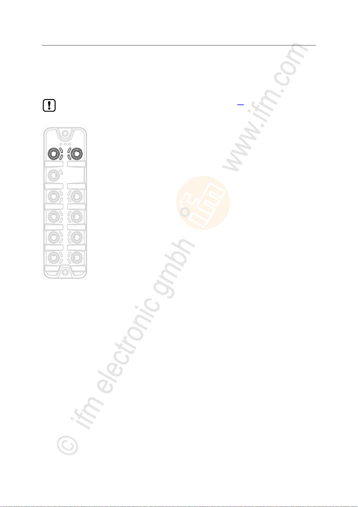
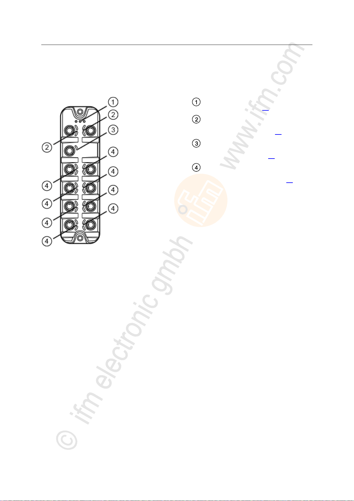
>
Status LEDs RDY, NET and MOD
→ Status LEDs (→ p. 24)
Status LEDs LNK and ACT of the
EtherNet/IP ports 1 (X21) and 2 (X22)
→ Ethernet interface (→ p. 24)
Status LED US of the power supply
(X31)
→ Voltage supply (→ p. 25)
Status LEDs IOL and DI of the IO-Link
ports Class A (X01...X08)
→ IO-Link ports (Class A) (→ p. 25)
7.1 Overview
22025
23
ifm Operating Instructions IO-Link Master with EtherNet/IP interface StandardLine 8 Ports IP 65 / IP 67 (AL1122) 2017-05-31
Operating and display elements
>
Status LED
Description
RDY
green
on
Gateway functions properly
flashes 1 Hz
Error
flashes 5 Hz
Firmware update
off
Gateway does not function; Device reboots
NET
green
on
Connection with the EtherNet/IP PLC
off
No IP address
red
on
IP address is used twice
flashes
No connection with the EtherNet/IP PLC
MOD
green
on
No error
off
Voltage too low
red
on
Module failed
flashes
Configuration of the module has been changed
Status LED
Description
LNK
green
on
Ethernet connection established
off
No Ethernet connection
ACT
yellow
flashes
Data is transmitted via the Ethernet interface.
off
No data transmission
7.2 LED indicators
The device only has the following LED indicators:
>
7.2.1 Status LEDs
The RDY LED indicates the status of the gateway.
The NET LED (Network Status) indicates the status of the network.
The MOD LED (Module Status) indicates the status of the EtherNet/IP module.
22024
7707
>
7.2.2 Ethernet interface
Each Ethernet interface (X21, X22) has 2 LEDs (LNK and ACT). The LEDs indicate the status of the
Ethernet connection.
22027
24
ifm Operating Instructions IO-Link Master with EtherNet/IP interface StandardLine 8 Ports IP 65 / IP 67 (AL1122) 2017-05-31
Operating and display elements
>
Status LED
Description
US
green
on
The supply voltage Us is applied.
off
No supply voltage is applied or the applied supply voltage is too low.
Status LED
Description
IOL
yellow
on
Interface configured as DI/DO: Pin 4 (C/Q) =ON
off
Interface configured as DI/DO: Pin 4 (C/Q) = OFF
green
on
IO-Link transmission functions properly
flashes 1 Hz
Interface configured as IO-Link, but no IO-Link transmission
red
on
Short circuit or overload in supply voltage
flashes 1 Hz
Transmission error
DI
yellow
on
Digital input: Pin 2 (DI) = ON
off
Digital input : Pin 2 (DI) = OFF
7.2.3 Voltage supply
22026
The interface for voltage supply (X31) has the LED that is marked as US. The LED indicates the status
of the voltage supply.
>
7.2.4 IO-Link ports (Class A)
22029
Each IO-Link port Class A (X01 ... X08) has 2 LEDs marked as IOL and DI. The LEDs indicate the
status of the IO-Link port.
25

ifm Operating Instructions IO-Link Master with EtherNet/IP interface StandardLine 8 Ports IP 65 / IP 67 (AL1122) 2017-05-31
Configuration
8 Configuration
Remarks .................................................................................................................................................27
LR DEVICE: Configure the device .........................................................................................................32
LR DEVICE: Configure IO-Link devices .................................................................................................40
EtherNet/IP: Configure the device ..........................................................................................................42
EtherNet/IP: Configure IO-Link devices .................................................................................................47
EtherNet/IP: Programmers' notes ...........................................................................................................47
22367
26

ifm Operating Instructions IO-Link Master with EtherNet/IP interface StandardLine 8 Ports IP 65 / IP 67 (AL1122) 2017-05-31
Configuration
>
Supported configuration options .............................................................................................................28
Connection possibilities ..........................................................................................................................28
Offline parameter setting ........................................................................................................................31
VPN connection ......................................................................................................................................31
8.1 Remarks
22369
27
ifm Operating Instructions IO-Link Master with EtherNet/IP interface StandardLine 8 Ports IP 65 / IP 67 (AL1122) 2017-05-31
Configuration
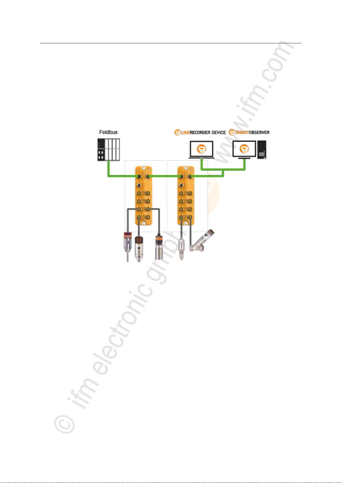
>
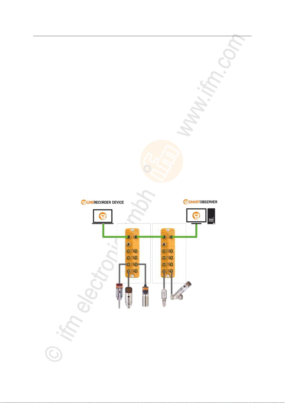
Parameter setting
IO-Link master: LR DEVICE
IO-Link device: LR DEVICE
Monitoring (optional):
LR SmartObserver
Topology (example):
8.1.1 Supported configuration options
1989
The AL1122 can be configured using the following options:
Parameter setting software LR DEVICE (version 1.1.0.87 or higher) (art. no.: QA0011/QA0012)
EtherNet/IP projection software
>
8.1.2 Connection possibilities
12742
Via the two EtherNet/IP interfaces X21 and X22, the AL1122 can be simultaneously connected with
the EtherNet/IP control level (PLC) and the IT infrastructure level (monitoring/parameter setting). The
following connection possibilities exist:
>
Operation without EtherNet/IP connection
4364
Operation as independent IO-Link master with connected IO-Link devices. As an option, several
IO-Link masters can be coupled via the EtherNet/IP interfaces. If necessary, the IO-Link masters can
be coupled with the IT infrastructure via industrial Ethernet in order to enable monitoring of the process
data of the connected IO-Link devices.
28
ifm Operating Instructions IO-Link Master with EtherNet/IP interface StandardLine 8 Ports IP 65 / IP 67 (AL1122) 2017-05-31
Configuration
>
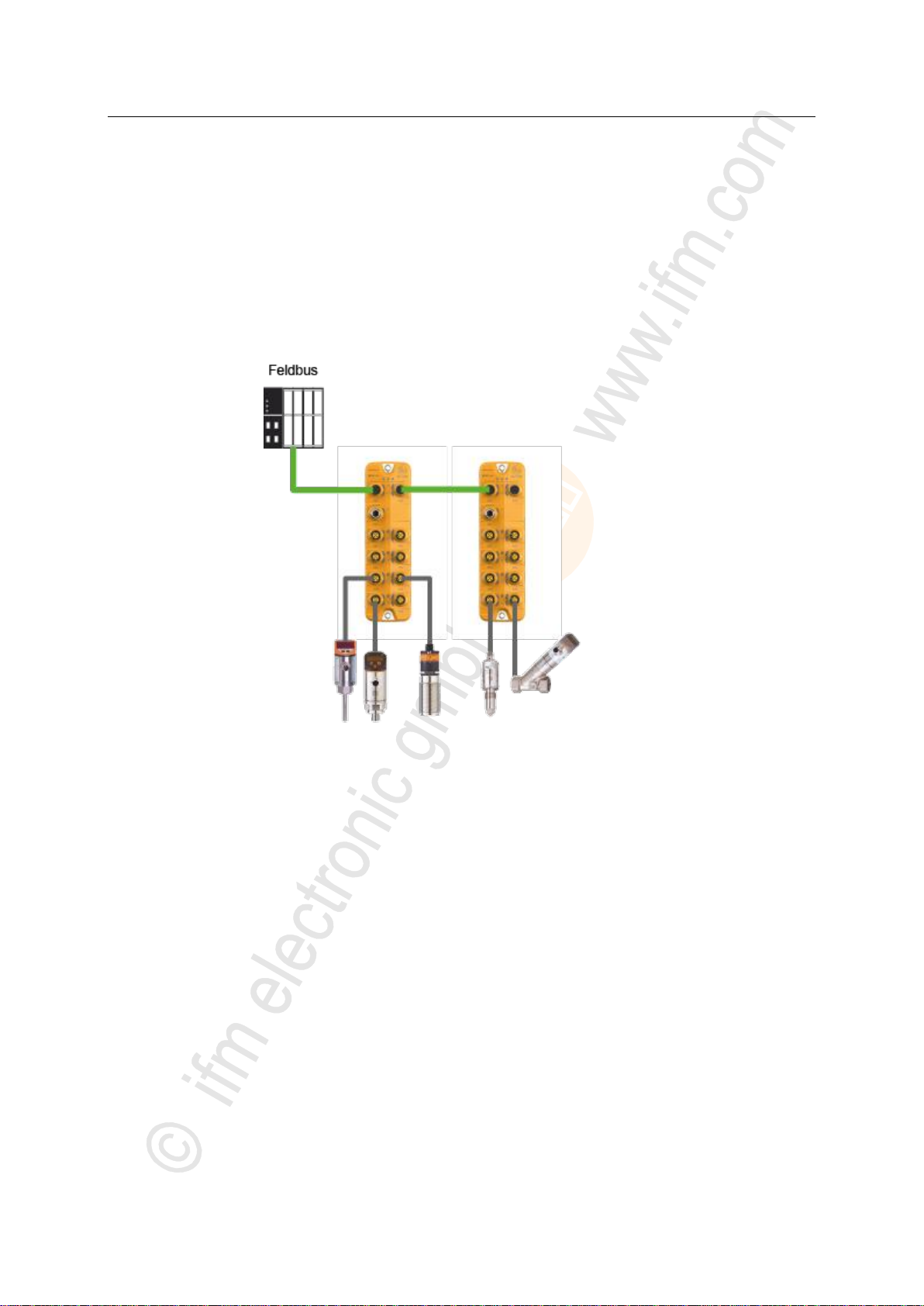
Parameter setting
IO-Link master: EtherNet/IP projection software
IO-Link device: EtherNet/IP projection software (acyclic services)
Monitoring:
EtherNet/IP projection software
Topology (example):
Operation with EtherNet/IP connection (without LR DEVICE)
Operation of the IO master as EtherNet/IP IO device. As an option, several IO-Link masters can be
coupled via the Ethernet interfaces X21 and X22. The complete monitoring of the process data and
processing of alarms takes place via EtherNet/IP mechanisms.
7396
29
ifm Operating Instructions IO-Link Master with EtherNet/IP interface StandardLine 8 Ports IP 65 / IP 67 (AL1122) 2017-05-31
Configuration
>
Parameter setting
IO-Link master: LR DEVICE and/or EtherNet/IP projection software
IO-Link device: LR DEVICE and/or EtherNet/IP projection software
Monitoring:
LR SmartObserver and/or EtherNet/IP projection software
Topology (example):
Operation with EtherNet/IP connection and LR DEVICE/LR SmartObserver
The AL1122 can be connected via the two Ethernet interfaces X21 and X22 simultaneously with the
EtherNet/IP control level (PLC) and the IT infrastructure level (monitoring/parameter setting).
7398
30
 Loading...