

IFM Electronic AL1030 Device Manual
Device manual
IO-Link master EtherCat
AL1030
UK
7391038/00 02/2016

IO-Link Master EtherCat
Contents
1 Preliminary note. . . . . . . . . . . . . . . . . . . . . . . . . . . . . . . . . . . . . . . . . . . . . . . . . 5
2 Safety instructions . . . . . . . . . . . . . . . . . . . . . . . . . . . . . . . . . . . . . . . . . . . . . . . 6
3 Documentation . . . . . . . . . . . . . . . . . . . . . . . . . . . . . . . . . . . . . . . . . . . . . . . . . . 7
4 Functions and features . . . . . . . . . . . . . . . . . . . . . . . . . . . . . . . . . . . . . . . . . . . . 7
5 Product description. . . . . . . . . . . . . . . . . . . . . . . . . . . . . . . . . . . . . . . . . . . . . . . 7
5.1 DI (digital input) . . . . . . . . . . . . . . . . . . . . . . . . . . . . . . . . . . . . . . . . . . . . . 7
5.2 IOL (IO-Link port) . . . . . . . . . . . . . . . . . . . . . . . . . . . . . . . . . . . . . . . . . . . . 8
5.3 Connections . . . . . . . . . . . . . . . . . . . . . . . . . . . . . . . . . . . . . . . . . . . . . . . . 8
5.4 Protection rating . . . . . . . . . . . . . . . . . . . . . . . . . . . . . . . . . . . . . . . . . . . . . 8
6 Scale drawings . . . . . . . . . . . . . . . . . . . . . . . . . . . . . . . . . . . . . . . . . . . . . . . . . . 9
6.1 Dimensions of the screw holes in the fixing clips . . . . . . . . . . . . . . . . . . . . 9
7 Structure of the device . . . . . . . . . . . . . . . . . . . . . . . . . . . . . . . . . . . . . . . . . . . 10
8 Electrical connection. . . . . . . . . . . . . . . . . . . . . . . . . . . . . . . . . . . . . . . . . . . . . 10
8.1 Supply voltages U
8.2 Power supply U
8.3 Power supply U
and U
S
S. . . . . . . . . . . . . . . . . . . . . . . . . . . . . . . . . . . . . . . . . . . . . . . . . . . . . . . . . . . . . . . . . . . . . . . . . . . . .
A. . . . . . . . . . . . . . . . . . . . . . . . . . . . . . . . . . . . . . . . . . . . . . . . . . . . . . . . . . . . . . . . . . . . . . . . . . . . .
A . . . . . . . . . . . . . . . . . . . . . . . . . . . . . . . . . . . . . . . . . . . . . . . . . . . . . . . . . . . . . . .
11
11
11
8.4 Diagnostic and status indicators. . . . . . . . . . . . . . . . . . . . . . . . . . . . . . . . 12
8.4.1 Diagnostics . . . . . . . . . . . . . . . . . . . . . . . . . . . . . . . . . . . . . . . . . . . 12
8.4.2 Status. . . . . . . . . . . . . . . . . . . . . . . . . . . . . . . . . . . . . . . . . . . . . . . . 12
9 Installation. . . . . . . . . . . . . . . . . . . . . . . . . . . . . . . . . . . . . . . . . . . . . . . . . . . . . 13
9.1 Mechanical strain . . . . . . . . . . . . . . . . . . . . . . . . . . . . . . . . . . . . . . . . . . . 13
9.2 Sources of interference . . . . . . . . . . . . . . . . . . . . . . . . . . . . . . . . . . . . . . 13
9.3 Cable routing in control cabinets . . . . . . . . . . . . . . . . . . . . . . . . . . . . . . . 13
9.4 Cable routing in buildings . . . . . . . . . . . . . . . . . . . . . . . . . . . . . . . . . . . . . 14
9.5 Cable routing outside buildings . . . . . . . . . . . . . . . . . . . . . . . . . . . . . . . . 14
9.6 Installing network/bus cables between buildings . . . . . . . . . . . . . . . . . . . 14
9.6.1 Causes of surge voltages . . . . . . . . . . . . . . . . . . . . . . . . . . . . . . . . 14
9.6.2 Equipotential bonding line . . . . . . . . . . . . . . . . . . . . . . . . . . . . . . . . 14
9.6.3 Surge protective devices . . . . . . . . . . . . . . . . . . . . . . . . . . . . . . . . . 15
9.7 Surge protection measures . . . . . . . . . . . . . . . . . . . . . . . . . . . . . . . . . . . 15
9.8 Grounding concept . . . . . . . . . . . . . . . . . . . . . . . . . . . . . . . . . . . . . . . . . . 16
9.9 Installation instructions . . . . . . . . . . . . . . . . . . . . . . . . . . . . . . . . . . . . . . . 16
9.10 Mounting distances . . . . . . . . . . . . . . . . . . . . . . . . . . . . . . . . . . . . . . . . 16
9.11 Mounting dimensions . . . . . . . . . . . . . . . . . . . . . . . . . . . . . . . . . . . . . . . 17
10 Features . . . . . . . . . . . . . . . . . . . . . . . . . . . . . . . . . . . . . . . . . . . . . . . . . . . . . 17
10.1 EtherCat characteristics . . . . . . . . . . . . . . . . . . . . . . . . . . . . . . . . . . . . . 17
10.2 IO-Link features . . . . . . . . . . . . . . . . . . . . . . . . . . . . . . . . . . . . . . . . . . . 18
10.3 General features. . . . . . . . . . . . . . . . . . . . . . . . . . . . . . . . . . . . . . . . . . . 18
11 Technical data . . . . . . . . . . . . . . . . . . . . . . . . . . . . . . . . . . . . . . . . . . . . . . . . . 19
12 Connections . . . . . . . . . . . . . . . . . . . . . . . . . . . . . . . . . . . . . . . . . . . . . . . . . . 23
2

IO-Link Master EtherCat
12.1 EtherCat and power supply connection . . . . . . . . . . . . . . . . . . . . . . . . . 23
12.2 Connecting IO Link ports and digital inputs . . . . . . . . . . . . . . . . . . . . . . 23
12.3 Pin connection EtherCat. . . . . . . . . . . . . . . . . . . . . . . . . . . . . . . . . . . . . 23
12.4 Pin connection voltage supply US/U
A . . . . . . . . . . . . . . . . . . . . . . . . . . . . . . . . . . . . . . . . . . . . . . . .
24
12.5 Pin connection of the inputs and IO-Link ports. . . . . . . . . . . . . . . . . . . . 24
12.5.1 Port class A (type A) . . . . . . . . . . . . . . . . . . . . . . . . . . . . . . . . . . . 24
12.5.2 Port class B (type B) . . . . . . . . . . . . . . . . . . . . . . . . . . . . . . . . . . . 24
12.6 Operating modes . . . . . . . . . . . . . . . . . . . . . . . . . . . . . . . . . . . . . . . . . . 24
12.7 Wiring information . . . . . . . . . . . . . . . . . . . . . . . . . . . . . . . . . . . . . . . . . 24
13 Identification . . . . . . . . . . . . . . . . . . . . . . . . . . . . . . . . . . . . . . . . . . . . . . . . . . 25
14 Configuration via rotary encoding switch . . . . . . . . . . . . . . . . . . . . . . . . . . . . 25
14.1 Reserved/invalid switch position . . . . . . . . . . . . . . . . . . . . . . . . . . . . . . 26
14.2 Configured Second Station Alias . . . . . . . . . . . . . . . . . . . . . . . . . . . . . . 26
14.3 Hot Connect . . . . . . . . . . . . . . . . . . . . . . . . . . . . . . . . . . . . . . . . . . . . . . 26
15 Local static and diagnostic displays . . . . . . . . . . . . . . . . . . . . . . . . . . . . . . . . 26
15.1 Displays for Ethernet ports and voltage supply . . . . . . . . . . . . . . . . . . . 26
15.2 Displaying the IO-Link ports and inputs . . . . . . . . . . . . . . . . . . . . . . . . . 28
16 EtherCAT . . . . . . . . . . . . . . . . . . . . . . . . . . . . . . . . . . . . . . . . . . . . . . . . . . . . 29
17 EtherCat Modular Device Profile (MDP). . . . . . . . . . . . . . . . . . . . . . . . . . . . . 29
18 EtherCat State Machine . . . . . . . . . . . . . . . . . . . . . . . . . . . . . . . . . . . . . . . . . 30
18.1 AL Control and AL Status Register . . . . . . . . . . . . . . . . . . . . . . . . . . . . . 31
18.2 AL Status Code Register . . . . . . . . . . . . . . . . . . . . . . . . . . . . . . . . . . . . 32
19 EtherCat communication methods . . . . . . . . . . . . . . . . . . . . . . . . . . . . . . . . . 32
20 EtherCAT synchronisation . . . . . . . . . . . . . . . . . . . . . . . . . . . . . . . . . . . . . . . 33
20.1 FreeRun . . . . . . . . . . . . . . . . . . . . . . . . . . . . . . . . . . . . . . . . . . . . . . . . . 33
20.2 SM Synchronous . . . . . . . . . . . . . . . . . . . . . . . . . . . . . . . . . . . . . . . . . . 33
UK
21 EtherCat object directory (CoE objects) . . . . . . . . . . . . . . . . . . . . . . . . . . . . . 33
22 CoE: type label . . . . . . . . . . . . . . . . . . . . . . . . . . . . . . . . . . . . . . . . . . . . . . . . 36
23 CoE: IO-Link port configuration . . . . . . . . . . . . . . . . . . . . . . . . . . . . . . . . . . . 37
23.1 Configuration of the operating mode . . . . . . . . . . . . . . . . . . . . . . . . . . . 37
23.2 Configuration of port parameters . . . . . . . . . . . . . . . . . . . . . . . . . . . . . . 38
23.3 Port status . . . . . . . . . . . . . . . . . . . . . . . . . . . . . . . . . . . . . . . . . . . . . . . 40
24 CoE: IO-Link module identification . . . . . . . . . . . . . . . . . . . . . . . . . . . . . . . . . 41
24.1 IO-Link device setting (configured). . . . . . . . . . . . . . . . . . . . . . . . . . . . . 42
24.2 IO-Link Device Information (detected) . . . . . . . . . . . . . . . . . . . . . . . . . . 44
25 CoE: IO-Link process data . . . . . . . . . . . . . . . . . . . . . . . . . . . . . . . . . . . . . . . 46
25.1 PDO mapping objects . . . . . . . . . . . . . . . . . . . . . . . . . . . . . . . . . . . . . . 46
25.2 Control and status objects . . . . . . . . . . . . . . . . . . . . . . . . . . . . . . . . . . . 49
26 Process data objects . . . . . . . . . . . . . . . . . . . . . . . . . . . . . . . . . . . . . . . . . . . 51
27 CoE: IO-Link substitute value behaviour . . . . . . . . . . . . . . . . . . . . . . . . . . . . 52
3

IO-Link Master EtherCat
28 CoE: IO-Link device diagnostic (events). . . . . . . . . . . . . . . . . . . . . . . . . . . . . 54
28.1 Structure of a diagnostic message . . . . . . . . . . . . . . . . . . . . . . . . . . . . . 57
28.2 Confirm diagnostic messages . . . . . . . . . . . . . . . . . . . . . . . . . . . . . . . . 59
28.3 Delete diagnostic messages . . . . . . . . . . . . . . . . . . . . . . . . . . . . . . . . . 59
28.4 Event Codes. . . . . . . . . . . . . . . . . . . . . . . . . . . . . . . . . . . . . . . . . . . . . . 60
29 AoE: IO-Link device parameter setting . . . . . . . . . . . . . . . . . . . . . . . . . . . . . . 62
29.1 AMS NetID . . . . . . . . . . . . . . . . . . . . . . . . . . . . . . . . . . . . . . . . . . . . . . . 63
29.2 Port number . . . . . . . . . . . . . . . . . . . . . . . . . . . . . . . . . . . . . . . . . . . . . . 63
29.3 AoE services. . . . . . . . . . . . . . . . . . . . . . . . . . . . . . . . . . . . . . . . . . . . . . 63
30 EtherCat emergency messages . . . . . . . . . . . . . . . . . . . . . . . . . . . . . . . . . . . 63
31 EtherCat SDO Abort Codes . . . . . . . . . . . . . . . . . . . . . . . . . . . . . . . . . . . . . . 65
32 Set-up . . . . . . . . . . . . . . . . . . . . . . . . . . . . . . . . . . . . . . . . . . . . . . . . . . . . . . . 66
32.1 Factory setting . . . . . . . . . . . . . . . . . . . . . . . . . . . . . . . . . . . . . . . . . . . . 66
32.2 Restore factory settings . . . . . . . . . . . . . . . . . . . . . . . . . . . . . . . . . . . . . 66
32.3 Firmware started . . . . . . . . . . . . . . . . . . . . . . . . . . . . . . . . . . . . . . . . . . 66
32.4 Firmware update . . . . . . . . . . . . . . . . . . . . . . . . . . . . . . . . . . . . . . . . . . 66
33 Connection monitoring/substitute value behaviour. . . . . . . . . . . . . . . . . . . . . 66
33.1 IO-Link Masters . . . . . . . . . . . . . . . . . . . . . . . . . . . . . . . . . . . . . . . . . . . 67
34 Web-based management (WBM) . . . . . . . . . . . . . . . . . . . . . . . . . . . . . . . . . . 67
35 Device description file (ESI) . . . . . . . . . . . . . . . . . . . . . . . . . . . . . . . . . . . . . . 67
36 Endianness. . . . . . . . . . . . . . . . . . . . . . . . . . . . . . . . . . . . . . . . . . . . . . . . . . . 67
37 Firmware update with the software CODESYS V3.5 . . . . . . . . . . . . . . . . . . . 68
38 Preparation . . . . . . . . . . . . . . . . . . . . . . . . . . . . . . . . . . . . . . . . . . . . . . . . . . . 68
38.1 Set up network . . . . . . . . . . . . . . . . . . . . . . . . . . . . . . . . . . . . . . . . . . . . 68
38.2 Open project. . . . . . . . . . . . . . . . . . . . . . . . . . . . . . . . . . . . . . . . . . . . . . 68
38.3 Set up EtherCat connection . . . . . . . . . . . . . . . . . . . . . . . . . . . . . . . . . . 69
39 Firmware update (step by step) . . . . . . . . . . . . . . . . . . . . . . . . . . . . . . . . . . . 71
40 Check firmware version . . . . . . . . . . . . . . . . . . . . . . . . . . . . . . . . . . . . . . . . . 73
4
IO-Link Master EtherCat
1 Preliminary note
This document applies to devices of the type "IO-Link master EtherCat" (art. no.
AL1030). These instructions are part of the device.
This document is intended for specialists. These specialists are people who are
qualified by their appropriate training and their experience to see risks and to
avoid possible hazards that may be caused during operation or maintenance of
the device. The document contains information about the correct handling of the
device.
Read this document before use to familiarise yourself with operating conditions,
installation and operation. Keep this document during the entire duration of use of
the device.
Adhere to the safety instructions.
Symbols
► Instruction
> Reaction, result
[…] Designation of keys, buttons or indications
→ Cross-reference
Important note
Non-compliance may result in malfunction or interference.
Information
Supplementary note
UK
Warnings used
WARNING
Warning of serious personal injury.
Death or serious irreversible injuries may result.
CAUTION
Warning of personal injury.
Slight reversible injuries may result.
NOTICE
Warning of damage to property.
5

IO-Link Master EtherCat
2 Safety instructions
These instructions contain texts and figures concerning the correct handling of the
device and must be read before installation or use.
Observe the operating instructions. Non-observance of the instructions, operation
which is not in accordance with use as prescribed below, wrong installation or
incorrect handling can seriously affect the safety of operators and machinery.
► Prepare installation
► Disconnect the device
► Ensure that devices cannot be accidentally restarted.
► Verify safe isolation from the supply.
► Earth and short circuit.
► Cover or enclose adjacent units that are live.
► Follow the specific mounting instructions of the device.
► Only suitably qualified personnel in accordance with EN 50 110-1/-2 (VDC 0105
part 100) is permitted to work on this device/system.
► Before installation and before touching the device ensure that you are free of
electrostatic charge.
► The functional earth (FE) must be connected to the protective earth (PE) or to
the potential equalisation. The system installer is responsible for implementing
this connection.
► Connecting cables and signal lines must be installed in such a manner that
inductive or capacitive interference do not impair the automatic functions.
► Install automation equipment and related operating elements in such a way that
they are protected against unintentional operation.
► Suitable safety hardware and software measures should be implemented for
the I/O interface so that a line or wire breakage on the signal side does not
result in undefined states in the automation device.
► Ensure a reliable electrical isolation of the low voltage for the 24 V supply.
Only use power supplies compliant with IEC 60 364-4-41 or HD 384.4.41 S2
(VDE 0100 part 410).
► Fluctuations or deviations of the mains voltage from the rated value must not
exceed the tolerance limits specified in the technical data; otherwise this may
cause malfunction and dangerous operation.
► E-stop devices to IEC/EN 60 204-1 must be effective in all operating modes of
the automation device. Unlatching the e-stop devices must not cause restart.
6

IO-Link Master EtherCat
► Devices that are designed for mounting in housings or control cabinets must
only be operated and controlled after they have been installed with the housing
closed. Desktop or portable units must only be operated and controlled in
enclosed housings.
► Measures should be taken to ensure the proper restart of programs interrupted
after a voltage dip or failure. This should not cause dangerous operating states
even for a short time. If necessary, an emergency stop must be carried out.
► Wherever faults in the automation system may cause personal injuries or
damage to property, external measures must be implemented to ensure a safe
operating state in the event of a fault or malfunction (e.g. by means of separate
limit switches, mechanical interlocks etc.)
► The electrical installation must be carried out in accordance with the relevant
regulations (e.g. with regard to cable cross-sections, fuses, PE).
► All work relating to transport, installation, commissioning and maintenance
must only be carried out by qualified personnel. (IEC 60 364 or HD 384 or
DIN VDE 0100 and national work safety regulations have to be observed).
UK
► All shrouds and doors must be kept closed during operation.
3 Documentation
This documentation relates to the hardware and firmware status at the time of
editing this manual. The features of the devices are continuously developed further
and improved.
The documentation applies to firmware version v2.2.x.x or higher.
4 Functions and features
The device has been designed for use within an EtherCAT network and designed
for use without a control cabinet in plant construction. It enables the operation of
up to eight IO-Link sensors/actuators and is also used to acquire digital signals.
5 Product description
5.1 DI (digital input)
The digital inputs receive the digital control signals from the process level. These
signals are transferred to the higher-level automation device via the network/bus.
The signal status is indicated via LEDs. The sensors are connected via M12 screw
connectors. The sensors are supplied from the sensor voltage US.
7

IO-Link Master EtherCat
5.2 IOL (IO-Link port)
These devices have IO-Link ports for communication-capable sensors so that the
automation device can make dynamic changes to the sensor parameters directly.
The IO-Link ports can be operated in the following operating modes:
– DI (behaves like a digital input supplied via U
– DO (behaves like a digital output supplied via U
– IO-Link (IOL sensor supplied via U
/ IOL actuator supplied via US and UA)
S
)
S
)
S
5.3 Connections
The bus, I/O devices and supply are connected via M12 screw connections. Each
device is connected directly to the network/bus system.
5.4 Protection rating
The devices have IP65/67 protection rating. To ensure IP65 / IP67 protection,
cover unused sockets with protective caps.
8
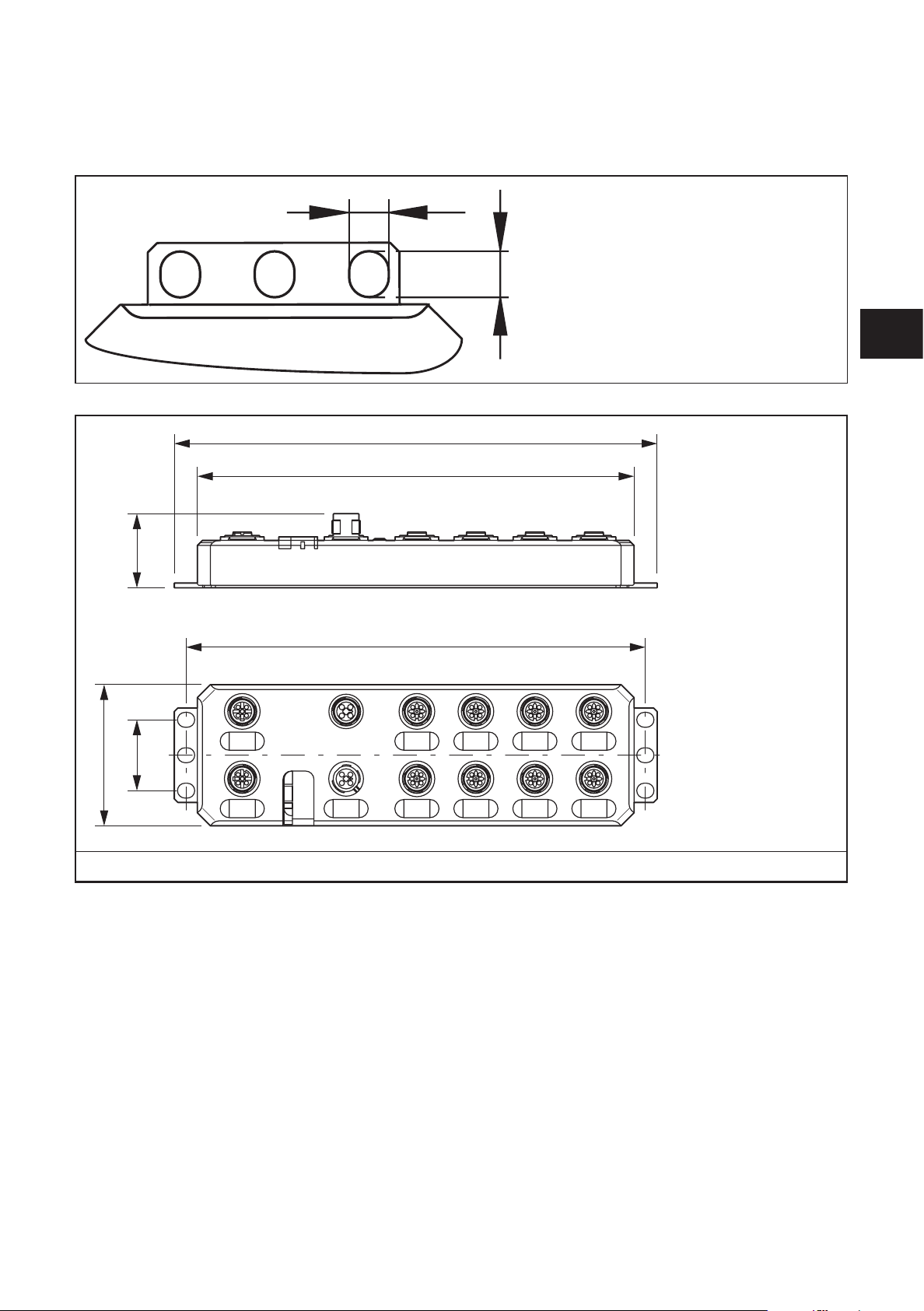
6 Scale drawings
6,3
212
60
6.1 Dimensions of the screw holes in the fixing clips
7,3
185
IO-Link Master EtherCat
UK
30,5
198,5
30
X21
Scale drawing AL1030
The fixing clips are firmly mounted.
9
IO-Link Master EtherCat
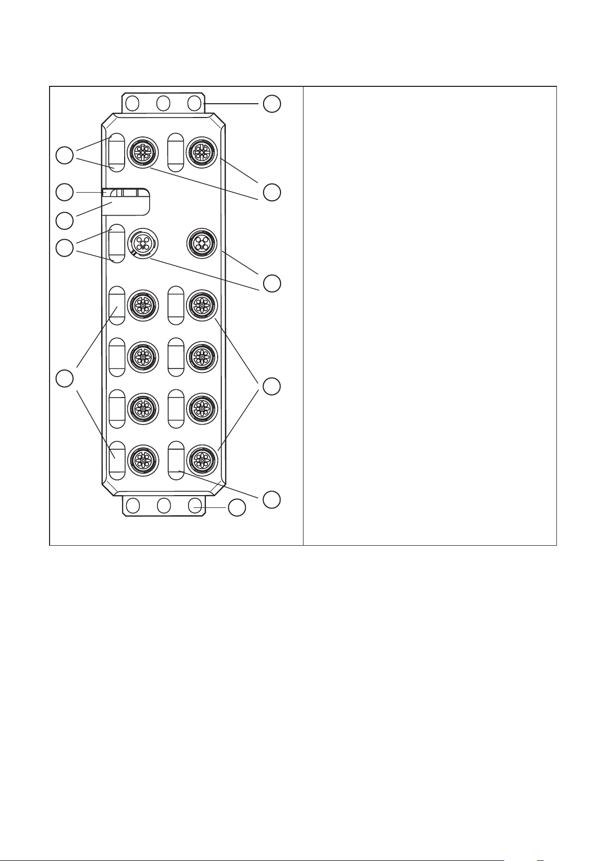
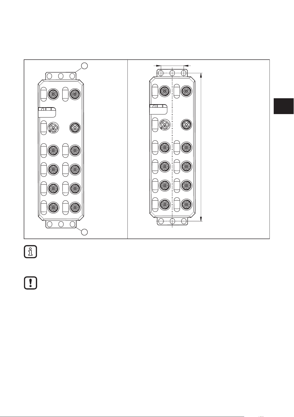
7 Structure of the device
10
9
8
7
6
1
2
3
4
1. Fixing clips ( FE connection)
2. Network or bus connection (IN, OUT)
3. Connections for the supply voltages
4. Connections for inputs/outputs or IO-Link ports
5. Markers for labelling
6. Status indicators of the inputs/outputs or the
IO-Link ports
7. Diagnostics and status indication for the supply
voltages
8. Rotary coding switch (no function for ProfiNet)
9. Diagnostics and status indicators for the network
/ bus system
10. Diagnostics and status indicators for the network (not for Profibus)
1
5
8 Electrical connection
For the devices, a distinction is made between two voltages:
– U
to supply the communications power and the sensors (always required),
S
– U
for supplying the actuators, only required for devices with fixed outputs or
A
for additional devices.
All supply voltages are connected via M12 connectors.
10

IO-Link Master EtherCat
Damage to the electronics
► Connect both supply voltages completely (to +24 V and GND).
Do not connect several supply voltages via one GND, as this will exceed the current rating of the
contacts.
8.1 Supply voltages US and U
A
The voltages US and UA are fed in at connection X31.
Power supply U
is required to supply the communications power of the device
S
electronics and to supply the sensors. It must be connected to every device. If this
supply voltage is disconnected, the device will not work.
► Install the power supply for the device electronics independently of the power
supply for the actuators.
► Protect the power supplies independently.
> This means that the bus can continue running even if some I/O devices are
switched off.
8.2 Power supply U
S
► Connect power supply Usfor the logic and sensors to socket X31.
► To supply additional devices, connect the cable for the outgoing supply voltage
to socket X32.
UK
Damage to the electronics
The current rating of the M12 connectors is 12 A per contact.
Make sure that this value is not exceeded. Please note that the connection for the outgoing supply
voltage is not monitored for overload. If the permissible current rating is exceeded, this may result in
damage to the connectors.
8.3 Power supply U
A
The voltage supply UA is only required for the supply of the IO-Link actuators. IOLink port in the operating mode DO is supplied via US.
Damage to the electronics
Power supplies U
and UA should only be supplied with SELV.
S
11

IO-Link Master EtherCat
8.4 Diagnostic and status indicators
8.4.1 Diagnostics
The diagnostic indicators (green/yellow/red) indicate whether an error is present
or not. In case of an error, they indicate the error type and location. The device is
operating correctly if all green indicators are on.
8.4.2 Status
The status indicators (yellow) indicate the signal state of the corresponding input/
output or of the IO-Link port. If the yellow status indicators are on, this indicates
signal state “1” of the input/output signal.
The devices have three main areas for diagnostics and status indicators.
● Indicators for the network/bus system (network/bus-specific) - Data
● Indicators for the power supplies - Power
● Indicators for the inputs and outputs and the IO-Link ports (device-specific) -
Signal
Data
Power
Signal
12

IO-Link Master EtherCat
9 Installation
When preparing for cable installation, the local conditions and the corresponding
mounting regulations are very important. Cables can be installed, for example, in
cable ducts or on cable bridges.
Data corruption and loss
A minimum distance between the cabling and possible sources of interference (e.g., machines,
welding equipment, power lines) is defined in the applicable regulations and standards. During
system planning and installation, these regulations and standards must be taken into account and
observed.
Protect the bus cables from sources of electric/magnetic interference and mechanical strain.
Observe the following guidelines regarding “electromagnetic compatibility” (EMC) to keep mechanical
risks and interference to a minimum.
9.1 Mechanical strain
► Choose the correct cable type for the respective application (e.g., indoor or
outdoor installation, drag chains).
UK
► Observe the minimum bending radius.
► Make sure that cables do not enter the shear area of moving machine parts.
► Do not install bus cables at right angles to driving routes and machine
movements.
► Use cable ducts and cable bridges.
► Observe the specifications of the cables used.
9.2 Sources of interference
Signal cables and power supply lines should not be installed in parallel.
► If necessary, metal isolating segments should be placed between the power
supply lines and signal cables.
► Only use connectors with metal housing and connect as much of the shielding
as possible to the housing.
► For outdoor cables between buildings, make sure that grounding is carried out
in accordance with “Installing network/bus cables between buildings”.
► During installation, all connector locking mechanisms (screws, union nuts)
must be firmly tightened in order to ensure the best possible contact between
shielding and ground. Before initial startup, the ground or shielding connection
of cables must be checked for low-resistance continuity.
9.3 Cable routing in control cabinets
► Install network/bus cables in separate cable ducts or separate cable bundles.
► Where possible, do not install network/bus cables parallel to power supply
lines.
13

IO-Link Master EtherCat
► Install network/bus cables at least 10 cm away from power lines.
9.4 Cable routing in buildings
► Where possible, use metal cable hangers.
► Do not install network/bus cables together with or parallel to power supply
lines.
► Separate network/bus cables on cable bridges or in cable ducts from power
supply lines using isolating segments.
► Install network/bus cables as far away as possible from sources of interference,
such as motors and welding equipment.
► For long cable connections, install an additional equipotential bonding line
between the terminal points.
9.5 Cable routing outside buildings
► Install network/bus cables in metal pipes that are grounded on both sides or in
concrete cable ducts with continuous reinforcement.
► For long cable connections, install an additional equipotential bonding line
between the terminal points.
9.6 Installing network/bus cables between buildings
9.6.1 Causes of surge voltages
Surge voltages occur as a result of switching operations, electrostatic discharge,
and lightning discharge. Surge voltages can be inductively, capacitively or
galvanically coupled into electrical cables for mains supply, measured value
transmission, and data transmission. In this way, surge voltages reach the power
supply units and the interfaces of systems and devices.
9.6.2 Equipotential bonding line
Install an additional equipotential bonding line between the grounding points of
buildings, preferably in the form of
– a metal-reinforced concrete channel,
– an additional grounding cable or
– a metal pipe.
14
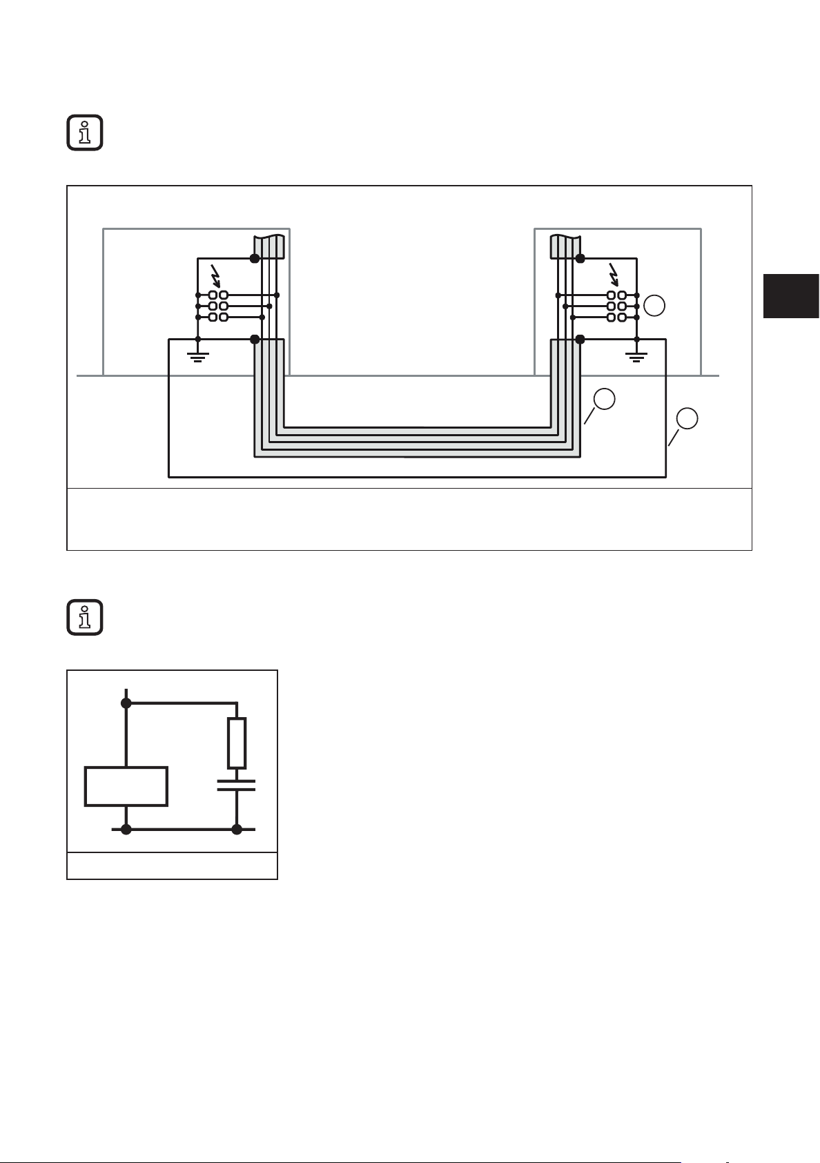
9.6.3 Surge protective devices
ifm recommends wiring all the wires of the cable to surge protective devices in order to protect the
devices against surge voltages.
Observe all national and international regulations when installing surge protective devices.
IO-Link Master EtherCat
1. Surge protective devices
2. Cable shielding
3. Equipotential bonding line
9.7 Surge protection measures
ifm recommends wiring relay coils or motor coils to an RC element in order to protect the devices
against interference. Depending on the application, the delay time of the relay can be increased by
approximately 1 ms.
1
2
3
UK
Relay coil with RC element
For the dimensioning of the RC element, the following values are recommended:
R = 100...200
Ω /
C = 220...470 nF
15

IO-Link Master EtherCat
9.8 Grounding concept
The devices operate in the low-level signal voltage range. In the case of low-level
signal devices, interference is discharged via functional earth (FE). Functional
earth (FE) is only used to discharge interference. It does not provide shock
protection for people.
Functional grounding
The devices are designed to be screwed onto a flat mounting surface.
► Ground the devices by means of the mounting screws of the fixing clips.
9.9 Installation instructions
Electrostatic discharge
The device contains components that can be damaged or destroyed by
electrostatic discharge. When handling the device, observe the necessary safety
precautions against electrostatic discharge (ESD) according to EN 61340-5-1 and
IEC 61340-5-1.
Damage to the electronics
► The device may only be installed and removed by qualified electricians in accordance with the
ESD regulations.
► Implement the FE connection using mounting screws, in order to ensure immunity to interference.
► To ensure IP65/IP67 protection, cover unused connections with protective caps.
► Only supply the sensors with the voltage U
► Avoid polarity reversal of supply voltages US and UA.
Data corruption or loss
► Implement the FE connection using mounting screws, in order to ensure immunity to interference.
which is provided at the terminal points.
S
9.10 Mounting distances
No specific distances are required between devices or between a device and a
cabinet door or cover. Mounting distances are determined solely by the plugs used
and the bending radii of the cables.
16
IO-Link Master EtherCat
1
30
9.11 Mounting dimensions
► Screw the device directly onto the flat mounting surface using the drill holes (1)
of the fixing clips.
198,5
UK
1
► Use standard M5 screws with toothed lock washer and self-locking nuts.
► Observe the maximum torque of the screws.
Functional grounding
► Functional grounding is crucial for interference-free operation. Ground the device by means of the
mounting screws of the fixing clips.
10 Features
10.1 EtherCat characteristics
● Connection to the EtherCAT network using M12 connectors (D-coded)
● 2 Ethernet ports
● Transmission rate 100 MBit/s
● Support of the EtherCat cycle time of min. 100 μs
● Automatic addressing
17

IO-Link Master EtherCat
● Identification
– Encoding switch for creation of the ID for the "Explicit Device ID" mechanism
– Configured Second Station Alias
● Hot Connect
● Acyclic data communication (mailbox protocols CoE, FoE, EoE and AoE)
● Device description through ESI
● Firmware that can be updated
● Specification: ETG.1000 V1.02, ETG.5001.3 (Annex K)
– Represented as modular EtherCat device via Modular Device Profile (MDP)
● Integrated web server for web-based management
● Connection of four IO-Link devices with additional digital input
● Connection of four IO-Link actuators with additional voltage supply
● Connection of IO-Link ports using M12 connectors (A-coded, 5-pos.)
● Diagnostic and status indicators
● Short-circuit and overload protection of the sensor supply
● Protection rating IP65/67
10.2 IO-Link features
● Connection of eight IO-Link devices
– 4 type A ports with an additional digital input
– 4 type B ports with an additional voltage supply
● Connection of IO-Link ports using M12 connectors (A-coded, 5-pos.)
● Parameter setting of devices via the AoE protocol
● Parameter data on the master
● Configurable process data
● IO-Link specification v1.1
10.3 General features
● Diagnostic and status indicators
● Short-circuit and overload protection of the sensor supply
● Protection rating IP65/67
18

11 Technical data
General data
Housing material Pocan
Weight [kg] 0.48
Ambient temperature (operation) [°C] -25 ...60
Ambient temperature (storage/transport) [°C] -25...85
Permissible humidity (operation) [%] 5...95
IO-Link Master EtherCat
Air pressure (operation) [kPa] 70...106 (up to 3000 m above sea
level)
Air pressure (storage/transport) [kPa] 70...106 (up to 3000 m above sea
level)
Protection rating IP65 / IP67
Protection class III, IEC 61140, EN 61140,
VDE 0140-1
Connection data
Connection type M12 connector
EtherCAT interface
Number 2
Connection type M12 connectors, D-coded
Designation connection point Copper cable
Number of positions 4
Transmission rate [MBits/s] 10/100 (with auto-negotiation)
Cycle time [µs] < 100
UK
EtherCAT
Type of unit EtherCat slave
Mailbox protocols CANopen over EtherCat,
File access over EtherCat
Type of addressing Auto-increment addressing
Fixed position addressing
Logical addressing
Specification ETG.1000 V1.02
Supply of the module electronics and the sensors (U
Connection type M12 connector (T-coded)
Number of positions 4
Designation U
Supply voltage [V] 24 DC
Nominal supply voltage range [V] 19...31.2 DC
Typical current consumption [mA] 180 ±15 % (at 24 V DC)
)
S
S
(including all tolerances, including
ripple)
19

IO-Link Master EtherCat
Max. current consumption [A] 12
Supply of the actuators
Connection type M12 connector (T-coded)
Number of positions 4
Designation U
A
Supply voltage [V] 24 DC
Nominal supply voltage range [V] 18...31.2 DC
(including all tolerances, including
ripple)
Typical current consumption [mA] 28 ±15 % (at 24 V DC)
Max. current consumption [A] 12
Supply of the IO-Link ports
Peripheral supply voltage [V] 24 DC
Nominal current for every IO-Link port [mA] 200 (short-term during start-up up
to 1.6 A)
Nominal current for each device [A] 1.6
Overload protection electronic in the unit
Permissible conductor length to the sensor [m] < 20
IO-Link ports in the digital input mode (DI)
Number of inputs max. 8 (EN 61131-2 type 1)
Connection type M12 connector, X01 ... X04 double
occupancy
Connection technology 2 / 3 wires
Nominal input voltage [V] 24 DC
Nominal input current [mA] typ. 3
Sensor current [mA] max. 200 for each channel from
L+/L-
Total current consumption [A] max. 1.6 from L+/L-
Input voltage range "0" signal [V] -3...5 DC
Input voltage range "1" signal [V] 15...30 DC
Input filter time [µs] < 1000
Overload protection, short-circuit protection of sensor supply electronic
IO-Link ports in the digital output mode (DO)
Number of outputs Max. 8
Connection type M12 connector, X01 ... X04 double
occupancy
Connection technology 2 / 3 wire
Nominal output voltage [V] 24 DC
20

IO-Link Master EtherCat
Output current for each channel [mA] 200
Output current for each device [A] 1.6
Nominal load, ohmic [W] 12 (48 Ω; with nominal voltage)
inductive nominal load [VA] 12
Signal delay [µs] Max. 150 (at power on)
Signal delay [µs] Max. 200 (at power off)
Switching frequency max. 5500 per second
Switching frequency max. 1 per second
Limitation of the voltage induced on circuit interruption [V] -15 DC
Output voltage when switched off [V] max. 1
Output current when switched off [µA] max. 300
Behaviour with overload Switching off with automatic restart
Overload protection, short-circuit protection of the outputs electronic
Digital inputs on pin 2 with type A ports
Number of inputs 4 (EN 61131-2 type 1)
Connection type M12 connector, X01 ... X04 double
(1.2 H; 12 Ω; with nominal voltage)
(with load current)
(with inductive nominal load)
occupancy
UK
Connection technology 2 / 3 wire
Nominal input voltage [V] 24 DC
Nominal input current [mA] typ. 3
Sensor current [mA] Max. 200 for each channel from
L+/L-
Total current consumption [A] Max. 1.6 from L+/L-
Input voltage range "0" signal [V] -3...5 DC
Input voltage range "1" signal [V] 15...30 DC
Input filter time [µs] < 1000
Overload protection, short-circuit protection of sensor supply electronic
Potential isolation/isolation of the voltage ranges Test voltage
24 V supply (communications power and sensor supply, IO-Link
ports)/bus connection (Ethernet 1) [V]
24 V supply (communications power and sensor supply, IO-Link
ports)/bus connection (Ethernet 2) [V]
24 V supply (communications power and sensor supply, IO-Link
ports)/FE
500 AC, 50 Hz, 1 min
500 AC, 50 Hz, 1 min
500 AC, 50 Hz, 1 min
Bus connection (Ethernet 1) / FE [V] 500 AC, 50 Hz, 1 min
Bus connection (Ethernet 2) / FE [V] 500 AC, 50 Hz, 1 min
Bus connection (Ethernet 1) / bus connection (Ethernet 2) [V] 500 AC, 50 Hz, 1 min
21

IO-Link Master EtherCat
24 V-supply (actuator supply) /
24 V supply (communications power and sensor supply, IO-Link
ports) [V]
24 V supply (actuator supply)/bus connection (Ethernet 1) [V] 500 AC, 50 Hz, 1 min
24 V supply (actuator supply)/bus connection (Ethernet 2) [V] 500 AC, 50 Hz, 1 min
24 V supply (actuator supply)/FE [V] 500 AC, 50 Hz, 1 min
Mechanical tests
Vibration resistance in accordance with EN 60068-2-6/IEC 60068-2-6
[g]
Shock in accordance with EN 60068-2-27/IEC 60068-2-27 [g] 30, 11 ms duration, half-sine shock
Continuous shock according to EN 60068-2-27/IEC 60068-2-27 [g] 10
Conformity with the EMC Directive 2004/108/EG
Noise immunity test in accordance with EN 61000-6-2
Electrostatic discharge (ESD) EN 61000-4-2/IEC 61000-4-2 Criterion B; 6 kV contact discharge;
Electromagnetic fields EN 61000-4-3/IEC 61000-4-3 Criterion A; field intensity: 10 V/m
500 AC, 50 Hz, 1 min
5
pulse
8 kV air discharge
Fast transients (burst) EN 61000-4-4/IEC 61000-4-4 Criterion B, 2 kV
Transient surge voltage (surge) EN 61000-4-5/IEC 61000-4-5 Criterion B; Supply cables DC:
±0.5 kV / ±0.5 kV
(symmetric / asymmetric)
Conducted interference EN 61000-4-6/IEC 61000-4-6 Criterion A; Test voltage 10 V
Noise emission test according to EN 61000-6-4
Radio interference properties EN 55022 Class A
Approvals at www.ifm.com
22
12 Connections
EC IN
A
DI 1...4
IOL1...8
12
23
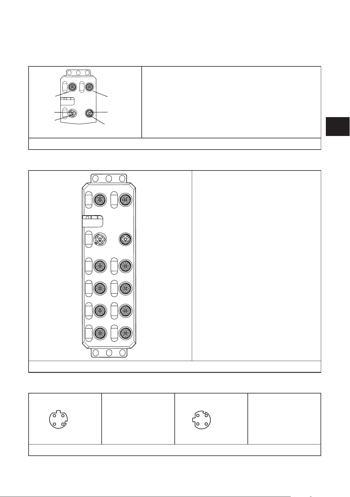
12.1 EtherCat and power supply connection
EC IN (X21): EtherCat IN
EC OUT (X22): EtherCat OUT
U
IN (X31): Power supply IN (logic and sensors)
EC OUT
U IN
S
U IN
A
► Implement the FE connection using mounting screws.
U OUT
S
U OUT
12.2 Connecting IO Link ports and digital inputs
S
U
IN (X31): Power supply IN (IO-Link actuators)
A
U
OUT (X32): Power supply OUT (logic and
S
sensors) for further devices)
U
OUT (X32): Power supply OUT (actuators) for further devices
A
IO-Link 1...8 (X01...X08): IO-Link ports 1...8
DI1...DI4 (X01...X04): Inputs 1...4
IO-Link Master EtherCat
UK
► Implement the FE connection using mounting screws.
12.3 Pin connection EtherCat
The shield is connected to FE in the device. The thread is used for additional shielding.
X01
X03
X05
X07
34
X02
X04
X06
X08
EC IN (X21)
1: TX +
2: RX +
3: TX -
4: RX -
EC OUT (X22)
1: TX +
2: RX +
1
4
3: TX -
4: RX -
23
 Loading...