

IFM Electronic AC903S, AC904S Original Operating Instructions
7390915/03 01/2017
Original operating instructions
Safety switch with guard locking
AC903S
AC904S
UK

2
Contents
1 Preliminary note ��������������������������������������������������������������������������������������������������� 4
1�1 Explanation of symbols ���������������������������������������������������������������������������������4
2 Safety instructions �����������������������������������������������������������������������������������������������4
3 Items supplied������������������������������������������������������������������������������������������������������5
4 Functions and features ����������������������������������������������������������������������������������������5
5 Structure and operating principle ������������������������������������������������������������������������� 6
5�1 Actuator version ��������������������������������������������������������������������������������������������� 7
5�2 Version AC903S (guard locking by spring force) �������������������������������������������7
5�3 Version AC904S (guard locking by solenoid force) ���������������������������������������7
5�4 Mechanical release ����������������������������������������������������������������������������������������9
6 Installation������������������������������������������������������������������������������������������������������������9
6�1 Installation instructions ����������������������������������������������������������������������������������9
6�1�1 Changing the actuating direction �������������������������������������������������������� 10
6�2 Protection against environmental influences �����������������������������������������������10
7 Electrical connection ������������������������������������������������������������������������������������������ 11
7�1 Wiring����������������������������������������������������������������������������������������������������������� 11
8 Set-up ���������������������������������������������������������������������������������������������������������������� 11
8�1 Setting of the AS-Interface address ������������������������������������������������������������� 11
8�2 Configuration in the AS-Interface safety monitor ����������������������������������������� 11
8�2�1 Monitor with extended functions ���������������������������������������������������������12
9 Operation ����������������������������������������������������������������������������������������������������������� 13
9�1 LED indicators / AS-Interface status messages ������������������������������������������13
10 Function check and troubleshooting ���������������������������������������������������������������� 14
10�1 Mechanical function check ������������������������������������������������������������������������14
10�2 Electrical function check ����������������������������������������������������������������������������14
10�3 Troubleshooting �����������������������������������������������������������������������������������������14
11 Scale drawing ��������������������������������������������������������������������������������������������������16
12 Technical data �������������������������������������������������������������������������������������������������� 17
13 Terms and abbreviations ����������������������������������������������������������������������������������18
14 Data bit table����������������������������������������������������������������������������������������������������19

3
UK
15 Standards and approvals ��������������������������������������������������������������������������������� 22
15�1 Directives and standards ���������������������������������������������������������������������������22
15�2 Approvals ��������������������������������������������������������������������������������������������������� 22
4
1 Preliminary note
Technical data, approvals, accessories and further information at
www�ifm�com�
1.1 Explanation of symbols
► Instructions
> Reaction, result
→ Cross-reference
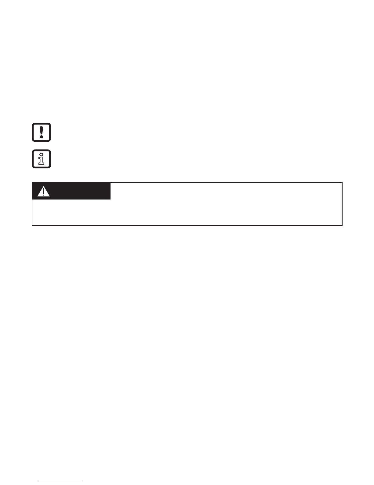
Important note
Non-compliance may result in malfunction or interference�
Information
Supplementary note�
WARNING
Warning of serious personal injury�
Death or serious irreversible injuries may result�
2 Safety instructions
• Follow the operating instructions�
• Improper use may result in malfunctions of the unit� This can lead to personal
injury and/or damage to property during operation of the machine� For this
reason note all remarks on installation and handling given in this document�
Also adhere to the safety instructions for the operation of the whole installation�
• In case of non-observance of notes or standards, especially when tampering
with and/or modifying the unit, any liability and warranty is excluded�
• The unit must be installed, connected and put into operation by a qualified
electrician trained in safety technology�
• The applicable technical standards for the corresponding application must be
complied with�
• For installation the requirements according to EN 60204-1 must be observed�
• In case of malfunction of the unit please contact the manufacturer� Tampering
with the unit is not allowed�

5
UK
• Disconnect the unit externally before handling it� Also disconnect any
independently supplied relay load circuits�
• After installation of the system perform a complete function check�
• Only use the unit under the specified operating conditions (→ 12 Technical
data)� In case of special operating conditions please contact the manufacturer�
• Use only as described below (→ 4).
• Safety switches fulfil a personal protection function� Incorrect installation or
tampering can lead to serious injury�
• Safety components must not be bypassed (bridging of contacts), turned away,
removed or otherwise rendered ineffective�
• On this point, take particular note of the measures to reduce the possibilities of
bypassing in EN ISO 14119: 2013�
• The switching operation must only be triggered by actuators specially provided
for this purpose which are permanently connected to the safety guard�
• A complete safety-related system normally consists of several signalling
devices, sensors, evaluation units and concepts for a safe shut-down� The
manufacturer of a machine or installation is responsible for a correct and safe
overall function�
• All safety instructions and specifications in the operating instructions of the
AS-Interface safety monitor must be adhered to�
3 Items supplied
• 1 AS-Interface safety switch type AC90xS
• 1 operating instructions safety switch with guard locking, ident no� 7390915�
If one of the above-mentioned components is missing or damaged, please contact
one of the ifm branch offices�
4 Functions and features
AS-Interface safety switches type AC903S/AC904S operate as slaves on the
safety bus AS-Interface Safety at Work and function as electromagnetic interlock
devices with guard locking� The actuator has a low coding level�
In combination with a guard and the machine control system this safety
component prevents the safety guard from being opened while there is potential of

6
exposure to a mechanical hazard�
For the control system this means the following:
- Switch-on commands which cause hazardous situations must become active
only when the safety guard is in a protective position and the guard locking in
locked position�
- The locked position of the guard locking must be released only when the
hazardous situation is no longer present�
Before safety switches are used, a risk assessment must be performed on the
machine, e�g� according to
- EN ISO 13849, Safety of machinery - Safety-related parts of control systems
- EN 12100-1, Safety of machinery - General principles for design - Risk
assessment and risk reduction
Correct use includes compliance with the relevant requirements for installation
and operation, in particular
- IEC 62061, Safety of machinery - Functional safety of safety-related electrical,
electronic and programmable electronic control systems
- EN ISO 13849, Safety of machinery - Safety-related parts of control systems
- EN 14119, Interlocking devices associated with guards
- EN 60204-1, Electrical equipment of machines
The user is responsible for a safe integration of the device into a safe
overall system�
► Validate the whole system, e�g� to EN ISO 13849-2�
If the simplified procedure to EN ISO 13849-1:2016 (section 6�3) is used for
validation, the performance level (PL) may be reduced in the event of several
units being connected in series� If a data sheet is supplied with the product, the
specifications of the data sheet apply in case of deviations from the operating
instructions�
5 Structure and operating principle
AS-Interface safety switches, type AC903S/AC904S feature a slave interface to
the safety bus AS-Interface Safety at Work� They enable locking of movable safety
guards�

7
UK
There is a rotatable camshaft in the head of the switch that is blocked/released
via the locking bolt� When the actuator is inserted/removed or when the guard
locking is activated/released the locking bolt is moved� The switching contacts are
activated�
When the camshaft is blocked (guard locking active) the actuator cannot be
drawn out of the switch head� For reasons of design, the guard locking can only
be activated if the protective equipment is closed (protected against incorrect
locking)�
Position monitoring of the safety guard and monitoring of interlocking are
performed via two separate contact elements (door monitoring contact SK and
solenoid monitoring contact ÜK)�
When the safety guard is closed and the guard locking is active, each AS-i safety
switch transmits a switch-specific unique safety code sequence comprising 8x4
bits via the AS-Interface bus� This code sequence is evaluated by an AS-Interface
safety monitor� The positively driven contact SK for door monitoring is represented
by the AS-Interface input bits D0 and D1� The solenoid monitoring contact ÜK is
represented by the AS-Interface input bits D2 and D3�
► Configure the safety switch in the AS-Interface safety monitor accordingly (refer
to the operating instructions of the AS-Interface safety monitor and the data bit
table)�
5.1 Actuator version
Actuator S for the AS-i safety switches AC903S/AC904S without insertion funnel�
5.2 Version AC903S (guard locking by spring force)
The locking bolt is held in locked position by spring force and is
electromagnetically released� The spring-interlocked guard locking operates
normally closed� In the event of interruption of the solenoid power supply the
safety guard cannot be opened immediately�
For process protection the interlocking solenoid can be switched by software via
the AS-Interface output bit D0�
 Loading...