

IFM Electronic AC5225 Original Device Manual
Original Device Manual
AS-i IO-Link Gateway
AC5225
Device state: AF
IO-Link: v. 1.0
ifm firmware: v. 1.16
AS-i master profile: M4
English
7390705
_02_UK
2016
-06-24
1

ifm Device Manual AS-i IO-Link-Gateway (AC5225) Firmware V1.16 2017-11-20
Contents
Contents
1 On this manual 4
1.1 What do the symbols and formats mean? ........................................................................... 4
1.2 What devices are described in this manual? ....................................................................... 5
1.3 How is this documentation structured? ................................................................................ 5
1.4 History of the instructions ..................................................................................................... 5
2 Safety instructions 6
2.1 Please note .......................................................................................................................... 6
2.2 What previous knowledge is required? ................................................................................ 7
2.3 Start-up behaviour of the controller...................................................................................... 7
2.4 Notes: serial number ............................................................................................................ 8
2.5 Notes: TEST inputs .............................................................................................................. 8
3 System description 9
3.1 Information about the device ................................................................................................ 9
3.2 What is IO-Link?.................................................................................................................10
3.2.1 Introduction ................................................................................................................................. 10
3.2.2 IO-Link system architecture ........................................................................................................ 11
3.2.3 IO-Link flow of information .......................................................................................................... 12
3.3 Description of the device software .....................................................................................13
3.3.1 User characteristics .................................................................................................................... 13
3.3.2 System interface ......................................................................................................................... 13
3.3.3 User interface ............................................................................................................................. 13
3.3.4 Software interface ...................................................................................................................... 13
3.3.5 Communication interface ............................................................................................................ 14
3.3.6 Operating states ......................................................................................................................... 14
4 AS-i parameters 15
4.1 Configuration of the process data image ...........................................................................15
4.2 Data assignment with P0=1 ...............................................................................................16
4.2.1 Transfer switching signals .......................................................................................................... 16
4.2.2 Transfer values ........................................................................................................................... 16
5 IO-Link services 17
5.1 Acyclic IO-Link services .....................................................................................................17
5.1.1 Code 16 – Acyclic standard read requests ................................................................................. 17
5.1.2 Code 20 – Acyclic device group read requests .......................................................................... 17
5.1.3 Code 21 – Acyclic device group write request services .............................................................. 18
5.1.4 Code 30 – Acyclic device group exchange request services ...................................................... 18
5.2 Standard services ..............................................................................................................19
5.2.1 Standard ID object ...................................................................................................................... 19
5.2.2 Standard diagnosis object .......................................................................................................... 19
5.2.3 Standard device group object ..................................................................................................... 20
5.3 Device group services ........................................................................................................21
5.3.1 Device group ID object ............................................................................................................... 22
5.3.2 Device group diagnosis object .................................................................................................... 23
5.3.3 IO-Link gateway configuration .................................................................................................... 25
5.3.4 IO-Link port configuration ........................................................................................................... 26
5.3.5 Process data assignment ........................................................................................................... 28
5.3.6 Exchange acyclic process data .................................................................................................. 31
5.3.7 Read diagnosis dataset .............................................................................................................. 33
5.3.8 Exchange device parameters ..................................................................................................... 42
2

ifm Device Manual AS-i IO-Link-Gateway (AC5225) Firmware V1.16 2017-11-20
Contents
6 Troubleshooting 44
6.1 Check if green LED [PWR] lights .......................................................................................44
6.2 Check if red LED [FAULT] lights or is flashing ...................................................................44
6.3 Test device supply voltage .................................................................................................44
6.4 Connect the unit .................................................................................................................44
7 Approvals, standards for IO-Link 45
8 Glossary of Terms 46
9 Index 62
10 ifm weltweit • ifm worldwide • ifm à l’échelle internationale 65
3

ifm Device Manual AS-i IO-Link-Gateway (AC5225) Firmware V1.16 2017-11-20
On this manual What do the symbols and formats mean?
What do the symbols and formats mean? ............................................................................................. 4
What devices are described in this manual? ......................................................................................... 5
How is this documentation structured? ................................................................................................. 5
History of the instructions ...................................................................................................................... 5
WARNING
Death or serious irreversible injuries may result.
CAUTION
Slight reversible injuries may result.
NOTICE
Property damage is to be expected or may result.
Important notes concerning malfunctions or disturbances
Other remarks
► ...
Request for action
> ...
Reaction, result
→ ...
"see"
abc
Cross-reference
123
0x123
0b010
Decimal number
Hexadecimal number
Binary number
[...]
Designation of pushbuttons, buttons or indications
1 On this manual
6089
6088
© All rights reserved by ifm electronic gmbh. No part of this manual may be reproduced and used
without the consent of ifm electronic gmbh.
All product names, pictures, companies or other brands used on our pages are the property of the respective rights owners:
• AS-i is the property of the AS-International Association, (→ www.as-interface.net)
• CAN is the property of the CiA (CAN in Automation e.V.), Germany (→ www.can-cia.org)
• CODESYS™ is the property of the 3S – Smart Software Solutions GmbH, Germany (→ www.codesys.com)
• DeviceNet™ is the property of the ODVA™ (Open DeviceNet Vendor Association), USA (→ www.odva.org)
• EtherNet/IP® is the property of the →ODVA™
• IO-Link® (→ www.io-link.com) is the property of the →PROFIBUS Nutzerorganisation e.V., Germany
• ISOBUS is the property of the AEF – Agricultural Industry Electronics Foundation e.V., Deutschland (→ www.aef-
online.org)
• Microsoft® is the property of the Microsoft Corporation, USA (→ www.microsoft.com)
• PROFIBUS® is the property of the PROFIBUS Nutzerorganisation e.V., Germany (→ www.profibus.com)
• PROFINET® is the property of the →PROFIBUS Nutzerorganisation e.V., Germany
• Windows® is the property of the →Microsoft Corporation, USA
>
1.1 What do the symbols and formats mean?
The following symbols or pictograms illustrate the notes in our instructions:
203
4

ifm Device Manual AS-i IO-Link-Gateway (AC5225) Firmware V1.16 2017-11-20
On this manual What devices are described in this manual?
Date
Theme
Change
2009-06-30
New creation of the document
---
2016-06-02
Update to firmware version 1.16
Documentation structure
Identification numbers of the text sections
Configuration of the process data image
IO-Link gateway configuration
Process data assignment
>
1.2 What devices are described in this manual?
This manual describes the AS-i IO-Link module AC5225 from ifm electronic gmbh.
This manual describes the IO-Link technology in connection with this device.
about IO-Link → www.io-link.com.
>
1.3 How is this documentation structured?
This documentation is a combination of different types of manuals. It is for beginners and also a
reference for advanced users. This document is addressed to the programmers of the applications.
How to use this manual:
Refer to the table of contents to select a specific subject.
Using the index you can also quickly find a term you are looking for.
At the beginning of a chapter we will give you a brief overview of its contents.
Abbreviations and technical terms → Appendix.
In case of malfunctions or uncertainties please contact the manufacturer at:
→ www.ifm.com > Select your country > [Contact].
We want to become even better! Each separate section has an identification number in the top right
corner. If you want to inform us about any inconsistencies, indicate this number with the title and the
language of this documentation. Thank you very much for your support!
We reserve the right to make alterations which can result in a change of contents of the
documentation. You can find the current version on ifm's website at:
→ www.ifm.com > Select your country > [Service] > [Download] > [Industrial communication]
>
5114
4373
1508
1.4 History of the instructions
What has been changed in this manual? An overview:
>
21789
5

ifm Device Manual AS-i IO-Link-Gateway (AC5225) Firmware V1.16 2017-11-20
Safety instructions Please note
Please note ............................................................................................................................................ 6
What previous knowledge is required? ................................................................................................. 7
Start-up behaviour of the controller ....................................................................................................... 7
Notes: serial number ............................................................................................................................. 8
Notes: TEST inputs ............................................................................................................................... 8
WARNING
Non-observance of these instructions can lead to property damage or personal injury.
ifm electronic gmbh does not assume any liability in this regard.
► The acting person must have read and understood the safety instructions and the corresponding
chapters in this manual before working on and with this device.
► The acting person must be authorised to work on the machine/equipment.
► The acting person must have the qualifications and training required to perform this work.
► Adhere to the technical data of the devices!
You can find the current data sheet on ifm's homepage at:
→ www.ifm.com > Select your country > [Data sheet search] > (article number.) > [Technical data
in PDF format]
► Note the installation and wiring information as well as the functions and features of the devices!
→ supplied installation instructions or on ifm's homepage:
→ www.ifm.com > Select your country > [Data sheet search] > (article number.) > [Operating
instructions]
► Please note the corrections and notes in the release notes for the existing documentation,
available on the ifm website:
→ www.ifm.com > Select your country > [Data sheet search] > (article number.) > [Operating
instructions]
2 Safety instructions
>
2.1 Please note
6091
11212
No characteristics are warranted with the information, notes and examples provided in this manual.
With the drawings, representations and examples given no responsibility for the system is assumed
and no application-specific particularities are taken into account.
► The manufacturer of the machine/equipment is responsible for ensuring the safety of the
machine/equipment.
► Follow the national and international regulations of the country in which the machine/installation is
to be placed on the market!
213
6

ifm Device Manual AS-i IO-Link-Gateway (AC5225) Firmware V1.16 2017-11-20
Safety instructions What previous knowledge is required?
WARNING
Danger due to unintentional and dangerous start of machine or plant sections!
► When creating the program, the programmer must ensure that no unintentional and dangerous
start of machines or plant sections after a fault (e.g. e-stop) and the following fault elimination can
occur!
Realise restart inhibit.
► In case of an error, set the outputs concerned to FALSE in the program!
>
2.2 What previous knowledge is required?
This document is intended for people with knowledge of control technology and PLC programming
with IEC 61131-3.
To program the PLC, the people should also be familiar with the CODESYS software.
The document is intended for specialists. These specialists are people who are qualified by their
training and their experience to see risks and to avoid possible hazards that may be caused during
operation or maintenance of a product. The document contains information about the correct handling
of the product.
Read this document before use to familiarise yourself with operating conditions, installation and
operation. Keep the document during the entire duration of use of the device.
Adhere to the safety instructions.
>
2.3 Start-up behaviour of the controller
6827
15233
11575
215
A restart can, for example, be caused by:
• voltage restoration after power failure
• reset after watchdog response because of too long a cycle time
• error elimination after an E-stop
To ensure a safe behaviour of the controller:
► Monitor the voltage supply in the application program.
► In case of an error switch off all relevant outputs in the application program.
► Monitor actuators which can cause hazardous movements in the application program (feedback).
► Monitor relay contacts which can cause hazardous movements in the application program
(feedback).
► If necessary, ensure that welded relay contacts in the application project cannot trigger or continue
hazardous movements.
7

ifm Device Manual AS-i IO-Link-Gateway (AC5225) Firmware V1.16 2017-11-20
Safety instructions Notes: serial number
>
2.4 Notes: serial number
20780
► In the user's production facility, draw a diagram of the controller network in the machine. Enter the
serial number of each controller installed into the network diagram.
► Before downloading a software component, read out this serial number and check the network
diagram to make sure that you are accessing the right controller.
>
2.5 Notes: TEST inputs
20781
► The TEST inputs of all the controllers in the machine should be wired individually and marked
clearly so that they can be properly allocated to the controllers.
► During a service access only activate the TEST input of the controller to be accessed.
>
8

ifm Device Manual AS-i IO-Link-Gateway (AC5225) Firmware V1.16 2017-11-20
System description Information about the device
Information about the device ................................................................................................................. 9
What is IO-Link? .................................................................................................................................. 10
Description of the device software ...................................................................................................... 13
3 System description
>
975
3.1 Information about the device
5118
Please also see the following documents:
→ separate operating instructions of the device:
→ www.ifm.com > Select your country > [Data sheet search] > (article no.) > [Further information].
This manual describes the AS-i IO-Link module AC5225 from ifm electronic gmbh.
Device status = AF
IO-Link = version 1.0
ifm firmware = version 1.16
required AS-i master profile = M4
This device provides the following functions:
Operate devices corresponding to the IO-Link standard (actuators, sensors, HMIs and other
devices with diagnostic capabilities) mixed with standard devices.
Connect all these devices with standard 3-pole cables.
Set the parameters of the IO-Link devices of the fieldbus master via AS-i.
Transfer cyclic and acyclic data between AS-i and IO-Link in both directions.
Provide digital and analogue data of the IO-Link devices via AS-i to a higher-level fieldbus master.
9

ifm Device Manual AS-i IO-Link-Gateway (AC5225) Firmware V1.16 2017-11-20
System description What is IO-Link?
Introduction .......................................................................................................................................... 10
IO-Link system architecture ................................................................................................................. 11
IO-Link flow of information ................................................................................................................... 12
→ www.io-link.com
Graphics: Typical signal curve for operation as IOLink (top) and as digitally-switching (bottom)
IO-Link communication by 24 V pulse
modulation, standard UART protocol
>
3.2 What is IO-Link?
5123
>
3.2.1 Introduction
5300
For fieldbuses one master communicates with several slaves which the master distinguishes on the
basis of the slave addresses. The sensors and actuators connected to the slaves perform either binary
or analogue operation. The slaves have to be equipped correspondingly. The parameters of the
sensors and actuators can be set during operation.
The IO-Link enables the operation of "smart" sensors and actuators on the existing fieldbus via special
modules. IO-Link sensors provide additional diagnostic information on a 3-pole standard cable besides
the normal switching output.
IO-Link is an open system: independent of the fieldbus and the manufacturer. The diagnostic interface
is supported by all leading bus systems.
Only the serial communication between the master and the slave are features both of the IO-Link and
the fieldbuses. Everything else is different:
There is no address setting since the data are only exchanged between two participants.
The IO-Link master communicates with the connected IO-Link device via a point-to-point
connection.
Remote parameter setting of the IO-Link device via the fieldbus is possible.
Advantages of the IO-Link system:
existing cable topology (here: standard AS-i cables) remains unchanged,
thanks to the point-to-point connection addressing of the devices is not necessary;
transmission of diagnostic data without additional wiring: exchange of process data and service
data between sensors / actuators and the controller,
transmission of analogue values without conversion losses,
fully compatible: Use in parallel to standard devices on the same bus.
10

ifm Device Manual AS-i IO-Link-Gateway (AC5225) Firmware V1.16 2017-11-20
System description What is IO-Link?
>
3.2.2 IO-Link system architecture
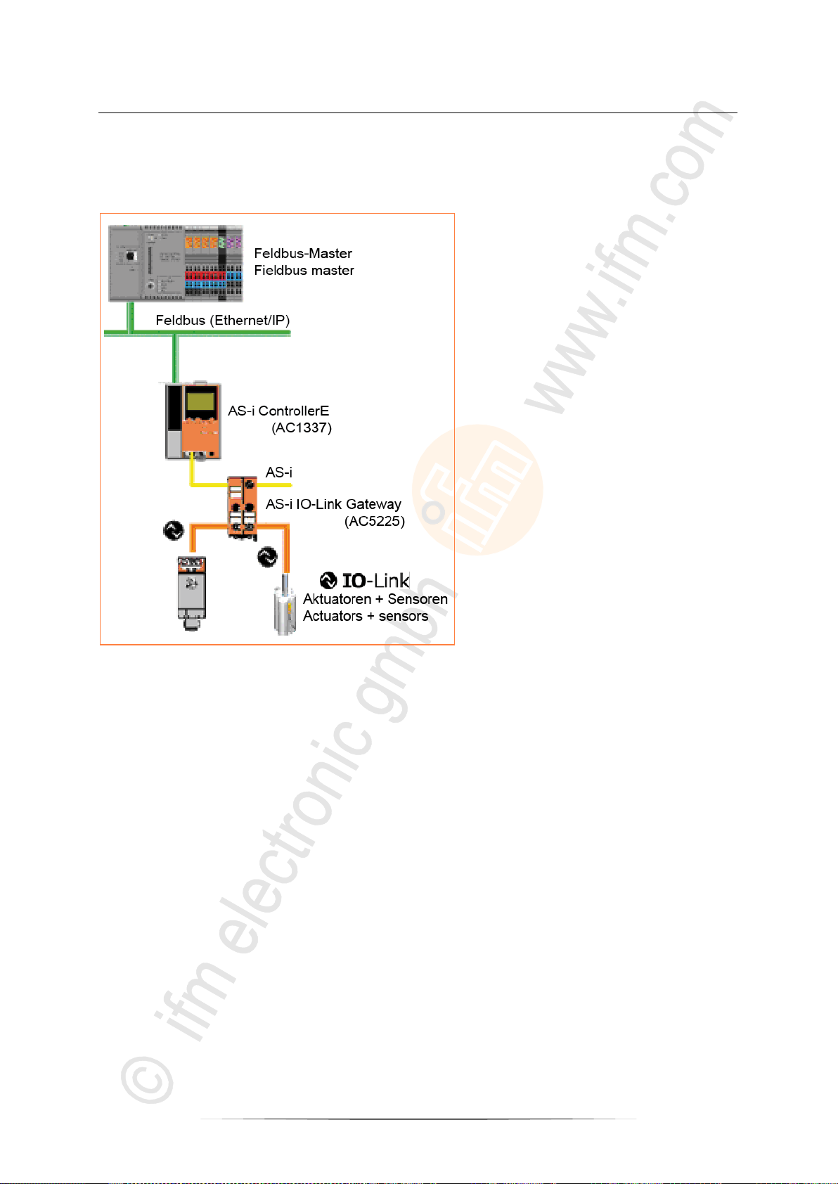
Example of an IO-Link system architecture:
5302
orange cable = IO-Link device
black cable = standard device
green cable = fieldbus device
11
ifm Device Manual AS-i IO-Link-Gateway (AC5225) Firmware V1.16 2017-11-20
System description What is IO-Link?
Graphics: IO-Link sensors communicate with the
fieldbus master via an AS-i IO-Link gateway and an AS-i
ControllerE.
> Signal transmission from the IO-Link
sensor to the IO-Link master (here:
AC5225) via standard sensor cable
(orange).
> Protocol conversion in the IO-Link
master to the AS-i slave (in the same
device).
> Data transmission via AS-i cable (yellow)
to the AS-i master (here AC1337).
> Evaluate data in the AS-i master.
> Transfer result to the higher-level
controller via Ethernet/IP (green).
>
3.2.3 IO-Link flow of information
Example of IO-Link flow of information:
5301
12

ifm Device Manual AS-i IO-Link-Gateway (AC5225) Firmware V1.16 2017-11-20
System description Description of the device software
User characteristics ............................................................................................................................. 13
System interface .................................................................................................................................. 13
User interface ...................................................................................................................................... 13
Software interface................................................................................................................................ 13
Communication interface ..................................................................................................................... 14
Operating states .................................................................................................................................. 14
>
3.3 Description of the device software
>
5124
3.3.1 User characteristics
5125
The presetting of the AS-i link gateway ensures operation of two sensors with two words of cyclic data
(process data) each.
The IO-Link port configuration can be changed via function blocks in a higher-level controller or a
configuration software on a service PC.
It is also possible to change the setting of the IO-Link devices via function blocks on the control level.
To do so the data are to be sent to the AS-i module via AS-i function calls. Then the AS-i IO-Link
gateway acts as a transparent transport channel*) and transfers the data to the connected device.
*) "transparent transport channel" means: The data are left unchanged over the whole communication line. Only the transfer
protocol changes between the AS-i and the IO-Link systems.
>
3.3.2 System interface
5126
The system interface is a largely transparent communication interface between the AS-i and the IOLink system. Transparency is restricted since the device is largely initiated automatically using default
values.
>
3.3.3 User interface
5127
The device does not feature a user interface. It is indirectly available as function calls. Settings of the
module and the connected IO-Link devices can be changed via these calls.
>
3.3.4 Software interface
The device only runs on AS-I masters with master profile M4 complying with the AS-i specification
V3.0 [AD5]. To be able to use all functions the master must also support the CTT2 protocol calls for
device groups amended in revision 2.
(Overview of the specifications chapter Approvals, standards to IO-Link (→ page 45))
13
5128

ifm Device Manual AS-i IO-Link-Gateway (AC5225) Firmware V1.16 2017-11-20
System description Description of the device software
>
3.3.5 Communication interface
The device has 2 communication interfaces:
via an AS-i communication to the usual AS-i standard to specification V3.0 [AD5],
via an IO-Link interface per port.
The IO-Link interface is implemented to specification 1.0 [AD1] or partly in anticipation of the
specification 1.1 [AD2].
(Overview of the specifications chapter Approvals, standards to IO-Link (→ page 45))
>
3.3.6 Operating states
The AS-i IO-Link gateway provides the following operating states:
Start-up
During reset / switch-on the module verifies the identity of the connected IO-Link devices
(manufacturer ID, device ID, function ID). In the "plug & comm" mode the identity check is not
made. Then cyclic operation is started.
If the "plug & comm" mode is not active, a newly connected device has to be configured before its
first use.
Cyclic operation
On the AS-i side data are exchanged normally, i.e. cyclically and acyclically.
On the IO-Link side normal operation is cyclic.
The gateway application assigns the data....
- referred to the port from AS-i to the IO-Link or
- referred to the port from the IO-Link to AS-i.
Error state with non-compatible device
If the connected device does not comply with the requirements, the gateway application signals
this to the higher-level system and waits for the connection of the correct device.
Error in the IO-Link communication
The faulty communication is displayed via a red LED on the respective IO-Link port. Errors,
messages and warnings from the IO-Link application trigger a periphery fault in the AS-i part
depending on the hardness set.
Removing and connecting the AS-i slave.
During operation you may remove the AS-i slave from the bus and connect another one or the
same one again. After connection of the AS-i slave rebooting is started in the same way as for
start-up ( above).
Removing and connecting IO-Link devices
During operation you may remove IO-Link devices and connect others or the same one again.
Connecting devices to the port is to be considered as an IO-Link start-up.
>
5130
5131
14

ifm Device Manual AS-i IO-Link-Gateway (AC5225) Firmware V1.16 2017-11-20
AS-i parameters Configuration of the process data image
Configuration of the process data image ............................................................................................ 15
Data assignment with P0=1................................................................................................................. 16
P0
Enable default data assignment
0
Assignment can be remanently overwritten by the command "Process data assignment
(→ page 28)"
1
Default process data assignment is active. (preset)
The overwriting of the process data assignment is blocked.
The assignment is not changed.
P1
reserved
0
reserved
1
reserved
P2
"Plug & comm" mode activated
0
Configuration can be remanently overwritten via "IO-Link gateway configuration".
1
"Plug & comm" mode is activated.
The overwriting of the IO-Link gateway configuration is blocked.
The configuration is not changed.
The "plug & comm" mode cannot be operated with digital outputs (actuators without IO-Link) and
can only be used to a limited extent with digital inputs (signal frozen during cyclic wakeup).
4 AS-i parameters
>
5132
4.1 Configuration of the process data image
6209
The process data image on the various AS-i transfer options are configured...
- via an acyclic command or
- via a defined default assignment.
The requested mode is selected via the AS-i parameter bit P0.
The IO-Link configuration can be set to the "plug & comm" mode by setting the AS-i parameter bit P2.
In that mode...
- the ports are operated in the scan mode,
- checking of the connected IO-Link devices is deactivated,
- saving parameters is deactivated.
15

ifm Device Manual AS-i IO-Link-Gateway (AC5225) Firmware V1.16 2017-11-20
AS-i parameters Data assignment with P0=1
P3
reserved
0
reserved
1
reserved
Port no.
Description
1
switching signal on D0
2
switching signal on D1
Port no.
Description of D0/D1
Description of the words
1
Bit 0 of the value on D0
words 1 + 2
2
Bit 0 of the value on D1
words 3 + 4
The IO-Link device parameters are always directly changed in the IO-Link device which usually saves
this data non-volatilely.
Deviations between the projected IO-Link configuration (manufacturer, device and function IDs) and
the configuration of the connected devices (with the "plug & comm" mode deactivated) lead to a
peripheral-fault message of the AS-i field module.
If one of these IDs is projected with 0x0000, the configuration of this ID is not checked.
Upcoming alarm events in the device also lead to a peripheral fault message of the AS-i field module.
The type of treatment of unique events must be set beforehand in the service "gateway configuration".
>
4.2 Data assignment with P0=1
6210
With P0 = 1 (default) the device-specific default data assignment is used. In the following table we
show how the input and output ports are supplied:
>
4.2.1 Transfer switching signals
6211
The data are transferred cyclically (typical: 5 ms).
>
4.2.2 Transfer values
Max. 4 input words and 4 output words are available per 16 bits for the transmission of parameter
values (depending on the device).
The data are transferred cyclically (typical: 160 ms per word).
>
6212
16

ifm Device Manual AS-i IO-Link-Gateway (AC5225) Firmware V1.16 2017-11-20
IO-Link services Acyclic IO-Link services
Acyclic IO-Link services ...................................................................................................................... 17
Standard services ................................................................................................................................ 19
Device group services ......................................................................................................................... 21
Code 16 – Acyclic standard read requests ......................................................................................... 17
Code 20 – Acyclic device group read requests ................................................................................... 17
Code 21 – Acyclic device group write request services ...................................................................... 18
Code 30 – Acyclic device group exchange request services .............................................................. 18
Index no..
Description
0
ID object
1
diagnosis object
80
device group
Index no..
Description
0
device group ID object
1
device group diagnosis object
2
IO-Link gateway configuration
3
process data assignment
5
port configuration ports 1…2
21 / 22
acyclic input process data ports 1 / 2
31 / 32
acyclic output process data ports 1 / 2
41 / 42
directly addressable diagnosis dataset ports 1 / 2
5 IO-Link services
>
5.1 Acyclic IO-Link services
The numbers used in the following tables are decimal numbers unless they are marked differently.
>
5.1.1 Code 16 – Acyclic standard read requests
>
5.1.2 Code 20 – Acyclic device group read requests
5135
5159
5136
5137
17

ifm Device Manual AS-i IO-Link-Gateway (AC5225) Firmware V1.16 2017-11-20
IO-Link services Acyclic IO-Link services
Index no..
Description
2
IO-Link gateway configuration
3
process data assignment
5
port configuration ports 1…2
31 / 32
acyclic output process data port 1 / 2
Index no..
Description
51 / 52
write compact parameters ports 1 / 2
61 / 62
read compact parameters ports 1 / 2
>
5.1.3 Code 21 – Acyclic device group write request services
>
5.1.4 Code 30 – Acyclic device group exchange request services
5138
5147
18

ifm Device Manual AS-i IO-Link-Gateway (AC5225) Firmware V1.16 2017-11-20
IO-Link services Standard services
Standard ID object ............................................................................................................................... 19
Standard diagnosis object ................................................................................................................... 19
Standard device group object .............................................................................................................. 20
Byte no.
Description
0
command code 16 = read standard
1
index 0 = ID object
2
length to be read = 5
Byte no.
Description
0
command code 80 = read standard OK
1
AS-i manufacturer ID (high) = 0x00
2
AS-i manufacturer ID (low) = 0x04
3
AS-i device ID (high) = 0x00
4
AS-i device ID (low) = 0x04
5
number of analogue AS-i inputs and outputs 0xDD (per 4 words transparent data)
Byte no.
Description
0
command code 16 = read standard
1
index 1 = diagnosis object
2
length to be read = 1
Byte no.
Description
0
command code 80 = read standard OK
1
standard diagnosis code:
0x00 = no error
0xFF = error, general
>
5.2 Standard services
>
5.2.1 Standard ID object
This object range describes and identifies the AS-i slave. Identification with reference to
manufacturer ID and
device ID.
Request read standard ID object
Reply read standard ID object
5153
5154
>
5.2.2 Standard diagnosis object
Query if module has an error on the AS-i side or functions without any error.
Request read standard diagnosis object
Reply read standard diagnosis object
5160
19

ifm Device Manual AS-i IO-Link-Gateway (AC5225) Firmware V1.16 2017-11-20
IO-Link services Standard services
Byte no.
Description
0
command code 16 = read standard
1
index 80 = device group object
2
length to be read = 4
Byte no.
Description
0
command code 80 = read standard OK
1
device group ID (high byte) 0x00
2
device group ID (low byte) = 0x4E
3
device group specific type (high byte) = 0x00
4
device group specific type (low byte) = 0x00
>
5.2.3 Standard device group object
This object describes an AS-i slave having IO-Link capabilities.
Request read standard device group object
Reply read standard device group object
0x4E means IO-Link device group
5167
20
 Loading...