

IFM Electronic AC412S Device Manual

>
7391190 / 03
Device Manual
SmartPLC SafeLine
with PROFIBUS slave interface
AC412S
Master profile: M4
Firmware: 4.3.2
English
>
04 / 2019

SmartPLC SafeLine with PROFIBUS slave interface
2
Contents
1 Preliminary note 6
1.1 Legal and copyright information ........................................................................................... 6
1.2 Purpose of the document ..................................................................................................... 6
1.3 Explanation of Symbols ....................................................................................................... 7
1.4 Overview: User documentation for AC4S ............................................................................ 8
1.5 Modification history .............................................................................................................. 8
2 Safety instructions 9
2.1 General safety instructions .................................................................................................. 9
2.2 Required background knowledge ........................................................................................ 9
2.3 Tampering with the unit ........................................................................................................ 9
3 System description 10
3.1 Intended use ......................................................................................................................11
3.1.1 Permitted use ............................................................................................................................. 11
3.1.2 Prohibited use ............................................................................................................................ 11
3.2 Information concerning the device .....................................................................................12
3.2.1 Overview .................................................................................................................................... 12
3.2.2 Operating elements .................................................................................................................... 13
3.2.3 Display elements ........................................................................................................................ 13
3.2.4 Interfaces .................................................................................................................................... 14
3.2.5 Type label ................................................................................................................................... 16
3.2.6 Required accessories ................................................................................................................. 16
3.3 Hardware ............................................................................................................................17
3.3.1 Safety architecture ..................................................................................................................... 18
3.3.2 Operating states of AC412S ....................................................................................................... 22
3.3.3 Monitoring and securing mechanisms ........................................................................................ 23
3.3.4 Error detection and processing ................................................................................................... 23
3.4 Software .............................................................................................................................26
3.4.1 Software modules of the device ................................................................................................. 26
3.4.2 Safety functions .......................................................................................................................... 26
3.4.3 Certified software components for safe applications .................................................................. 27
4 Mounting 28
4.1 Install device ......................................................................................................................28
5 Electrical connection 29
5.1 Wiring .................................................................................................................................29
5.2 Connect the supply voltage ................................................................................................29
5.2.1 Standard configuration: 24 V power supply and AS-i power supply/supplies ............................. 30
5.3 Connect devices to local I/O interface ...............................................................................31
5.3.1 Supported connection types ....................................................................................................... 31
5.3.2 Supported device types .............................................................................................................. 32
5.3.3 Connect sensors / actuators ....................................................................................................... 43
6 Operation 44
6.1 Control of the graphical user interface ...............................................................................44
6.1.1 Function keys ............................................................................................................................. 45
6.1.2 Arrow keys .................................................................................................................................. 45

SmartPLC SafeLine with PROFIBUS slave interface
3
6.2 Menu view ..........................................................................................................................46
6.2.1 Menu navigation ......................................................................................................................... 46
6.2.2 Navigation aids ........................................................................................................................... 47
6.3 Page view ...........................................................................................................................49
6.3.1 Navigate on a page .................................................................................................................... 49
6.3.2 Use navigation aids .................................................................................................................... 49
6.3.3 Description of the control elements ............................................................................................ 50
6.4 Remote access ..................................................................................................................62
6.4.1 General....................................................................................................................................... 62
6.4.2 Recommended browsers............................................................................................................ 62
6.4.3 Operating instructions ................................................................................................................ 63
7 Menu 66
7.1 Start screen ........................................................................................................................66
7.2 Menu functions ...................................................................................................................67
7.2.1 Additional functions .................................................................................................................... 67
7.3 Quick setup ........................................................................................................................68
7.3.1 Quick setup: Project AS-i networks ............................................................................................ 69
7.3.2 Quick setup: Configure the operating mode of the AS-i masters ................................................ 70
7.3.3 Quick setup: Configure the output access .................................................................................. 71
7.3.4 Quick setup: Access the device via QR code ............................................................................. 71
7.3.5 Quick setup: Configure the PROFIBUS interface ....................................................................... 72
7.3.6 Quick setup: Set the Konfigurationsschnittstelle ......................................................................... 73
7.3.7 Quick setup: Address the AS-i slaves connected to AS-i Master 1 ............................................ 75
7.3.8 Quick setup: Address the AS-i slaves connected to AS-i Master 2 ............................................ 76
7.4 AS-i 1 / AS-i 2 .....................................................................................................................77
7.4.1 AS-i 1 / AS-i 2: Master setup ...................................................................................................... 78
7.4.2 AS-i 1 / AS-i 2: Diagnosis ................................................................................................ ........... 80
7.4.3 AS-i 1 / AS-i 2: AS-i slaves ......................................................................................................... 82
7.5 System ...............................................................................................................................88
7.5.1 System: Programmable Logic Controller (PLC) .......................................................................... 89
7.5.2 System: Information ................................................................................................................... 95
7.5.3 System: Setup ............................................................................................................................ 96
7.5.4 System: Diagnosis .................................................................................................................... 108
7.6 Interfaces .........................................................................................................................109
7.6.1 Interfaces: Konfigurationsschnittstelle ...................................................................................... 110
7.6.2 Interfaces: PROFIBUS interface ............................................................................................... 114
7.7 Safety ...............................................................................................................................120
7.7.1 Safety: Status of the fail-safe slaves at AS-i Master 1 .............................................................. 121
7.7.2 Safety: Status of the fail-safe slaves at AS-i Master 2 .............................................................. 125
7.7.3 Safety: Local IOs ...................................................................................................................... 126
7.7.4 Safety: FSoE ............................................................................................................................ 130
7.7.5 Safety: System ......................................................................................................................... 131
7.8 ifm system solutions .........................................................................................................132
7.8.1 Notes on ifm system solutions .................................................................................................. 132
7.8.2 Show information about installed ifm apps ............................................................................... 134
7.8.3 Install single/basic app ............................................................................................................. 135
7.8.4 Install multi app ........................................................................................................................ 136
7.8.5 Update ifm apps ....................................................................................................................... 137
7.8.6 Uninstall ifm apps ..................................................................................................................... 137
8 Setup 138
8.1 Install device ....................................................................................................................138
8.2 Connect the device to the periphery ................................................................................138
8.2.1 PROFIBUS interface ................................................................................................................ 138
8.2.2 Configuration interface ............................................................................................................. 138
8.2.3 Install devices on the local I/O interface ................................................................................... 139
8.3 Install devices on the local I/O interface ..........................................................................139
8.4 Start screen 'Basic settings' .............................................................................................140
8.4.1 Change the basic settings of the device ................................................................................... 140

SmartPLC SafeLine with PROFIBUS slave interface
4
8.5 Notes on the firmware update ..........................................................................................142
8.6 Connect and address AS-i slaves ....................................................................................142
8.7 Set the Profibus interface .................................................................................................143
8.8 Setup of the configuration interface .................................................................................143
8.9 Replace standard AS-i slave ............................................................................................144
8.10 Replace safe AS-i slave ...................................................................................................144
9 Troubleshooting 145
9.1 Status LED .......................................................................................................................145
9.1.1 Status LED: Basic device ......................................................................................................... 145
9.2 Start screen: Status LEDs ................................................................................................146
9.2.1 Status of the web interface ....................................................................................................... 146
9.2.2 Operating mode of the AS-i master .......................................................................................... 146
9.2.3 Control instance of the AS-i outputs ......................................................................................... 146
9.3 Online diagnosis function .................................................................................................147
9.3.1 Message types ......................................................................................................................... 147
9.3.2 Locate error sources ................................................................................................................ 147
9.4 Online Support Centre (OSC) ..........................................................................................148
9.4.1 OSC: Display current messages .............................................................................................. 149
9.4.2 OSC: Show message history .................................................................................................... 150
9.5 Availability of the fail-safe PLC ........................................................................................151
9.6 Display diagnostic protocol ..............................................................................................151
10 Appendix 152
10.1 Technical data ..................................................................................................................153
10.1.1 Environmental conditions ......................................................................................................... 153
10.1.2 Safety classification .................................................................................................................. 153
10.1.3 Power supply connections ........................................................................................................ 153
10.1.4 Electrical data ........................................................................................................................... 154
10.1.5 Display elements ...................................................................................................................... 154
10.1.6 Housing .................................................................................................................................... 154
10.1.7 Interfaces .................................................................................................................................. 155
10.1.8 AS-interface .............................................................................................................................. 155
10.1.9 Programmable Logic Controller (PLC) ..................................................................................... 156
10.2 Address assignment in Ethernet networks ......................................................................157
10.3 Configuration interface: connection concepts ..................................................................158
10.3.1 Direct link .................................................................................................................................. 158
10.3.2 Connection via Ethernet network .............................................................................................. 158
10.4 AS-i master ......................................................................................................................159
10.4.1 Operating modes of the AS-i master ........................................................................................ 160
10.4.2 Master flags .............................................................................................................................. 162
10.5 AS-i slaves .......................................................................................................................163
10.5.1 Profiles of AS-i slaves............................................................................................................... 164
10.6 Fieldbus Profibus .............................................................................................................173
10.6.1 Fieldbus parameters ................................................................................................................. 173
10.6.2 Device-specific parameters ...................................................................................................... 174
10.6.3 Cyclic data ................................................................................................................................ 178
10.6.4 Acyclic data .............................................................................................................................. 202
10.6.5 I&M data ................................................................................................................................... 209
10.6.6 Fieldbus alarms ........................................................................................................................ 212
10.7 OSC messages ................................................................................................................221
10.7.1 OSC messages: System .......................................................................................................... 221
10.7.2 OSC messages: AS-i 1 / AS-i 2 ................................................................................................ 222
10.7.3 OSC messages: Safety module ............................................................................................... 223
10.7.4 OSC messages: Safety PLCopen function blocks .................................................................... 238
11 Index 239

SmartPLC SafeLine with PROFIBUS slave interface
5

SmartPLC SafeLine with PROFIBUS slave interface
6
1 Preliminary note
Content
Legal and copyright information ............................................................................................................ 6
Purpose of the document ...................................................................................................................... 6
Explanation of Symbols ......................................................................................................................... 7
Overview: User documentation for AC4S ............................................................................................. 8
Modification history ................................................................................................................................ 8
>
33203
1.1 Legal and copyright information
33117
© All rights reserved by ifm electronic gmbh. No part of this manual may be reproduced and used
without the consent of ifm electronic gmbh.
All product names, pictures, companies or other brands used on our pages are the property of the
respective rights owners:
AS-i is the property of the AS-International Association, (→ www.as-interface.net)
CAN is the property of the CiA (CAN in Automation e.V.), Germany (→ www.can-cia.org)
CODESYS™ is the property of the 3S – Smart Software Solutions GmbH, Germany
(→ www.codesys.com)
DeviceNet™ is the property of the ODVA™ (Open DeviceNet Vendor Association), USA
(→ www.odva.org)
EtherNet/IP® is the property of the → ODVA™
EtherCAT® is a registered trade mark and patented technology, licensed by Beckhoff Automation
GmbH, Germany
IO-Link® (→ www.io-link.com) is the property of the → PROFIBUS Nutzerorganisation e.V.,
Germany
ISOBUS is the property of the AEF – Agricultural Industry Electronics Foundation e.V.,
Deutschland (→ www.aef-online.org)
Microsoft® is the property of the Microsoft Corporation, USA (→ www.microsoft.com)
PROFIBUS® is the property of the PROFIBUS Nutzerorganisation e.V., Germany
(→ www.profibus.com)
PROFINET® is the property of the → PROFIBUS Nutzerorganisation e.V., Germany
Windows® is the property of the → Microsoft Corporation, USA
>
1.2 Purpose of the document
This document applies to devices of the type "SmartPLC AC4S with PROFIBUS" interface" (art. no.:
AC412S) with the firmware version 4.3.2.
These instructions describe the following topics:
Mounting and electrical connection of AC412S
Installation of additional devices (sensors, actuators) to the local I/O interface
Operation and configuration of the device via the menu (GUI and web interface)
Command channels, cyclic and acyclic data records
Error diagnostics and troubleshooting
42287
SmartPLC SafeLine with PROFIBUS slave interface
7
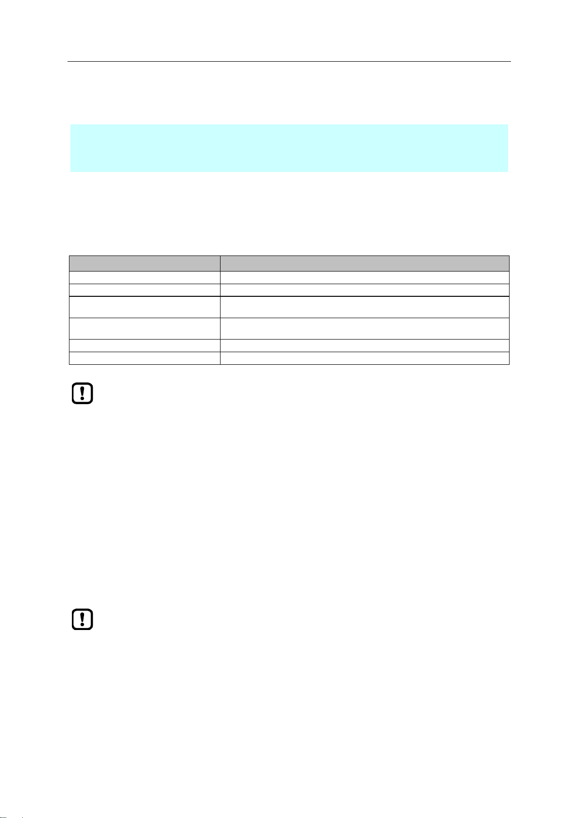
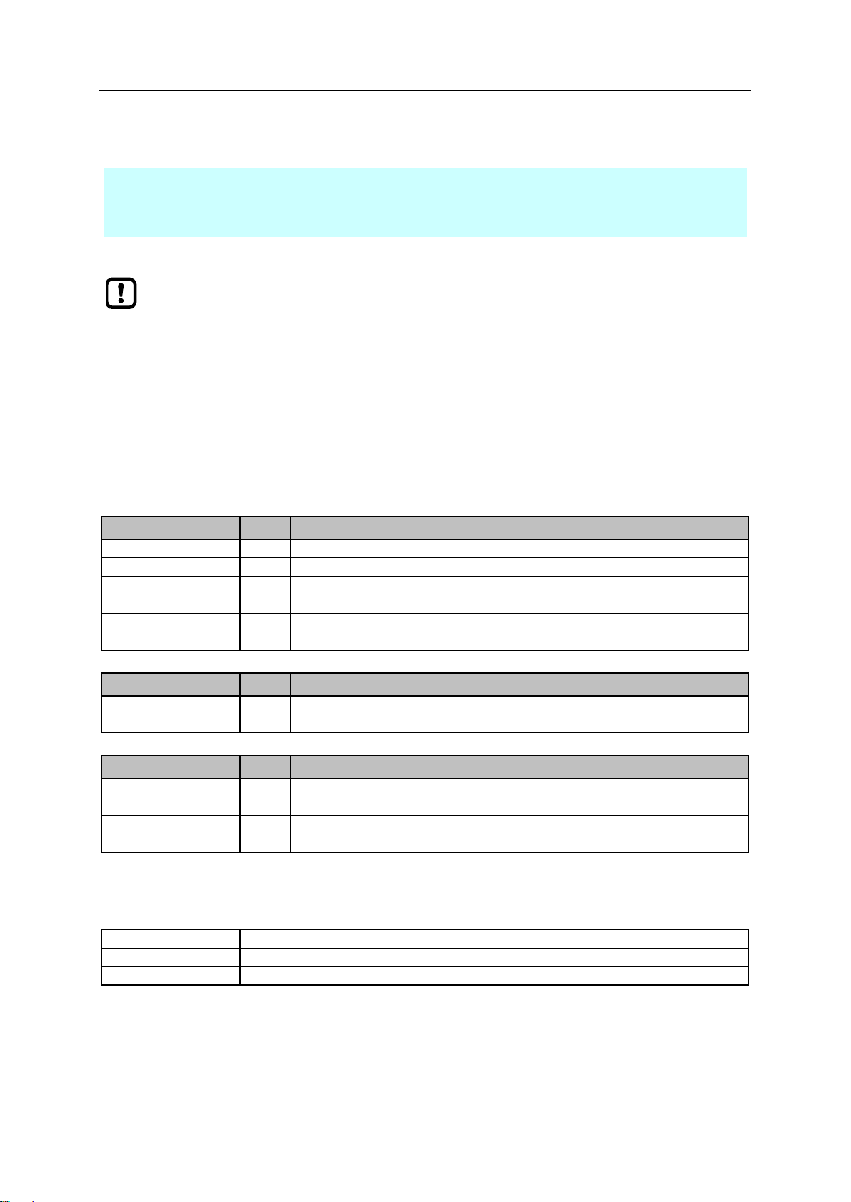
1.3 Explanation of Symbols
WARNING!
Death or serious irreversible injuries may result.
CAUTION!
Slight reversible injuries may result.
NOTICE!
Property damage is to be expected or may result.
Important note
Non-compliance can result in malfunction or interference
Information
Supplementary note
► ...
Request for action
> ...
Reaction, result
→ ...
"see"
abc
Cross-reference
123
0x123
0b010
Decimal number
Hexadecimal number
Binary number
[...]
Designation of pushbuttons, buttons or indications
34171
SmartPLC SafeLine with PROFIBUS slave interface
8
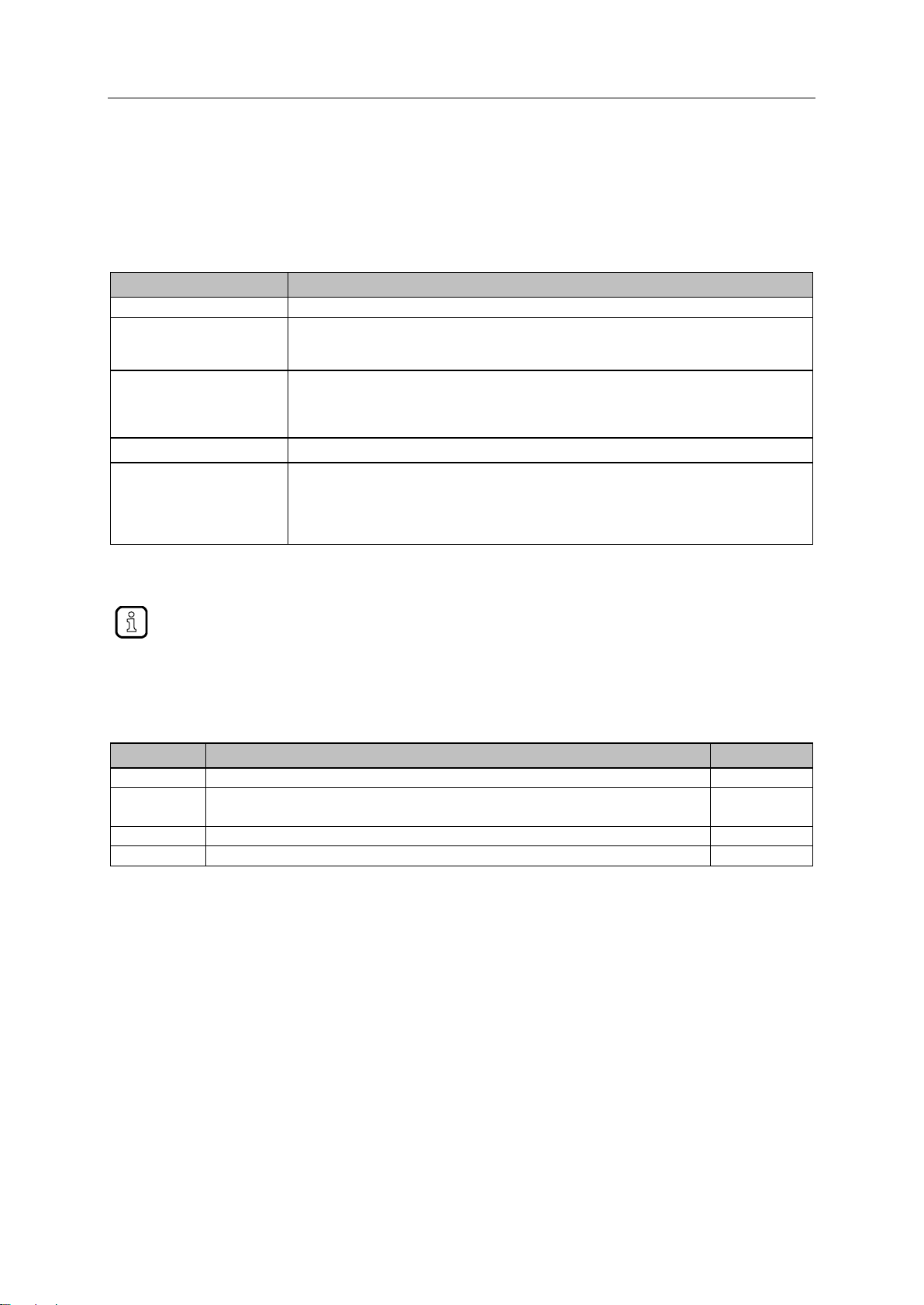
1.4 Overview: User documentation for AC4S
Document
Content / Description
Data sheet
Technical data of AC412S as a table
Operating instructions *
Notes on mounting and electrical installation of the AC412S
Set-up, description of the operating and display elements, maintenance information, scale
drawing
Device manual
Notes on operation of AC412S via GUI and web interface
Description of the cyclic and acyclic data records, fieldbus parameters and command
interface
Error description
Supplement device manual
Description of the acyclic data sets and the command interface
Programming manual
Creation of a project with the device using CODESYS
Configuration of the device using CODESYS
Programming of the Standard-SPS of the device
Programming of the fail-safe PLC of the device
Description of the device-specific CODESYS function libraries
All documents can be downloaded from ifm's website.
Version
Topic
Date
00
New creation of document
12 / 2017
01
Update to firmware 4.3.1
Changed: Restore device configuration
09 / 2018
02
Deleted: chapter 5.2.2 „Device supply via a joint power supply”
01 / 2019
03
Update to firmware 4.3.2
42309
ifm electronic provides the following user documentation for the models of the device class "Fail-safe
SmartPLC AC4S":
Legend:
*... The operating instructions are supplied with the device.
>
1.5 Modification history
34492
04 / 2019

SmartPLC SafeLine with PROFIBUS slave interface
9
2 Safety instructions
Content
General safety instructions .................................................................................................................... 9
Required background knowledge .......................................................................................................... 9
Tampering with the unit ......................................................................................................................... 9
WARNING!
Tampering with the unit.
> In case of non-compliance:
Possible affects on safety of operators and machinery
Expiration of liability and warranty
► Do not open the devices!
► Do not insert any objects into the devices!
► Prevent metal foreign bodies from penetrating!
>
28333
2.1 General safety instructions
41415
Read this document before setting up the product and keep it during the entire service life.
Only use the product for its intended purpose.
If the operating instructions or the technical data are not adhered to, personal injury and/or damage to
property may occur.
Improper or non-intended use may lead to malfunctions of the device, to unwanted effects in the
application or to a loss of the warranty claims.
The manufacturer assumes no liability for any consequences caused by tampering with the device or
incorrect use by the operator.
► Observe these operating instructions.
► Adhere to the warning notes on the product.
>
2.2 Required background knowledge
41648
This document is intended for specialists. Specialists are people who, based on their relevant training
and experience, are capable of identifying risks and avoiding potential hazards that may be caused
during operation or maintenance of the product.
For programming these people should also have knowledge of control technology experience in PLC
programming to IEC 61131-3.
The document contains information about the correct handling of the product.
>
2.3 Tampering with the unit
33190

SmartPLC SafeLine with PROFIBUS slave interface
10
3 System description
Content
Intended use ........................................................................................................................................ 11
Information concerning the device ...................................................................................................... 12
Hardware ............................................................................................................................................. 17
Software .............................................................................................................................................. 26
This chapter describes the structure and the components of the system.
42275

SmartPLC SafeLine with PROFIBUS slave interface
11
3.1 Intended use
Content
Permitted use ...................................................................................................................................... 11
Prohibited use ...................................................................................................................................... 11
>
3.1.1 Permitted use
AC412S can assume the following functions:
AS-i master in 2 separate AS-i networks
Fail-safe programmable logic controller (PLC) and standard PLC for acquiring, processing and
providing safe and non-safe data of the connected AS-i slaves and the channels of the local I/O
interface
Gateway for the transmission of standard control and user data between a higher-level
PROFIBUS controller and the slaves in the AS-i networks
>
3.1.2 Prohibited use
The device may not be used beyond the limits of the technical data (→ Technical data (→ S. 153))!
36928
42316
34228
SmartPLC SafeLine with PROFIBUS slave interface
12
3.2 Information concerning the device
Content
Overview .............................................................................................................................................. 12
Operating elements ............................................................................................................................. 13
Display elements ................................................................................................................................. 13
Interfaces ............................................................................................................................................. 14
Type label ............................................................................................................................................ 16
Required accessories .......................................................................................................................... 16
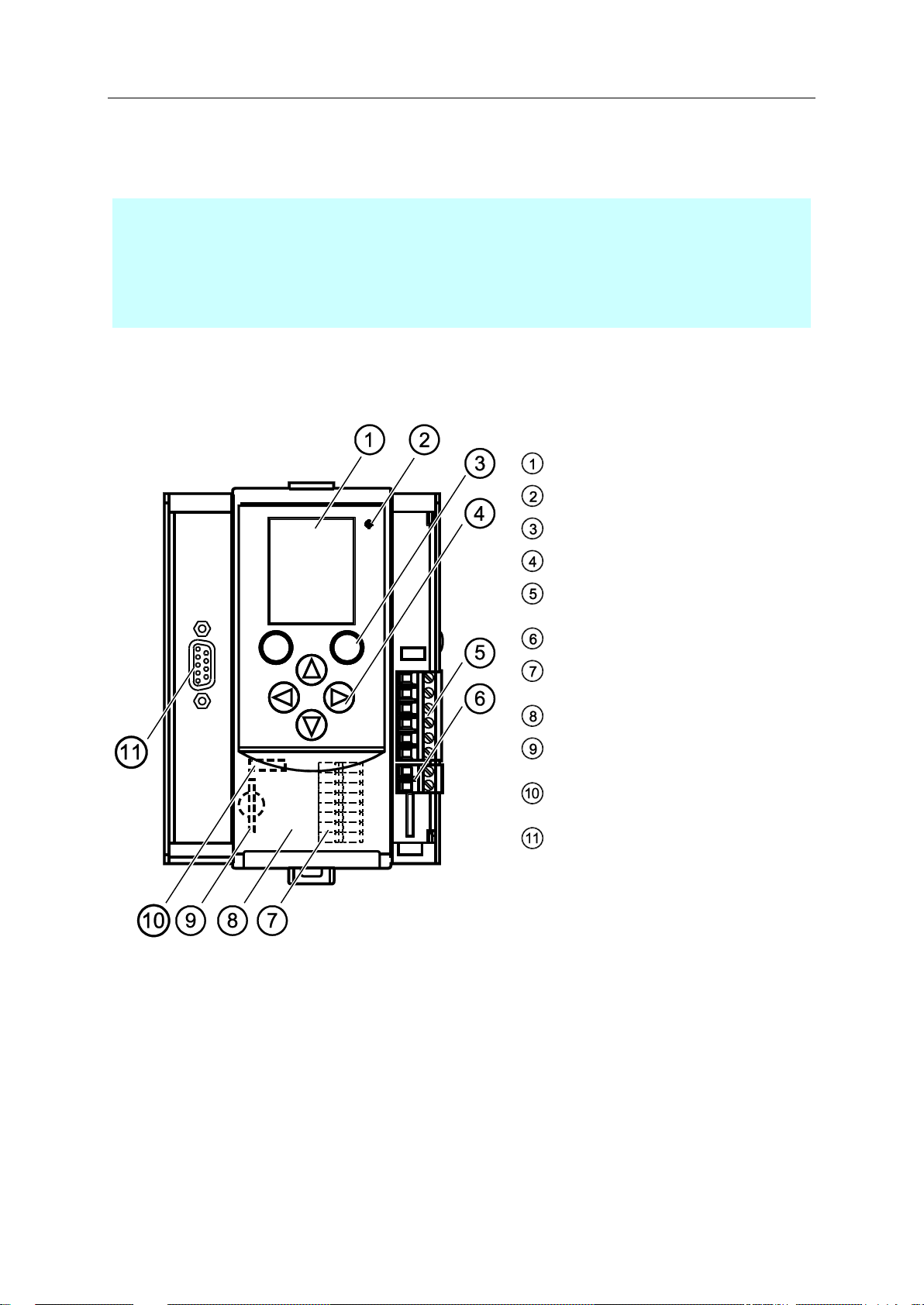
Legende:
Display
Status-LED (H1)
2 Funktionstasten
4 Pfeiltasten
Anschlussstecker (X1) für
AS-i 1, AS-i 2, Funktionserde
Anschlussstecker (X2) für AUX
Lokale Ein- und Ausgänge (X4)
(hinter der Frontklappe)
Frontklappe
Steckplatz für SD-Karte (X5)
(hinter der Frontklappe)
Ethernet-Konfigurationsschnittstelle (X3)
(hinter der Frontklappe)
PROFIBUS-Schnittstelle (X6)
>
3.2.1 Overview
36905
42308

SmartPLC SafeLine with PROFIBUS slave interface
13
3.2.2 Operating elements
36790
The device provides the following operating elements.
>
Arrow and function keys
36959
Below the display is the key panel with two function keys and four arrow keys. The operator controls
the Graphical User Interface (GUI) of the device with the keys.
Operating notes: → Operation (→ S. 44)
>
3.2.3 Display elements
36917
The device provides the following display elements:
>
Display
36894
The display is used to display the Graphical User Interface (GUI) of the device.
Operating notes: → Operation (→ S. 44)
Technical data: → Technical data (→ S. 153)
>
Status LEDs
36784
The device features the following status LEDs which display the current status of system components.
Meaning of the LED colours and flashing frequencies: → Status LED (→ S. 145)
SmartPLC SafeLine with PROFIBUS slave interface
14
3.2.4 Interfaces
Content
Ethernet configuration interface .......................................................................................................... 14
Local input/output interface ................................................................................................................. 14
SD card slot ......................................................................................................................................... 15
PROFIBUS fieldbus interface .............................................................................................................. 15
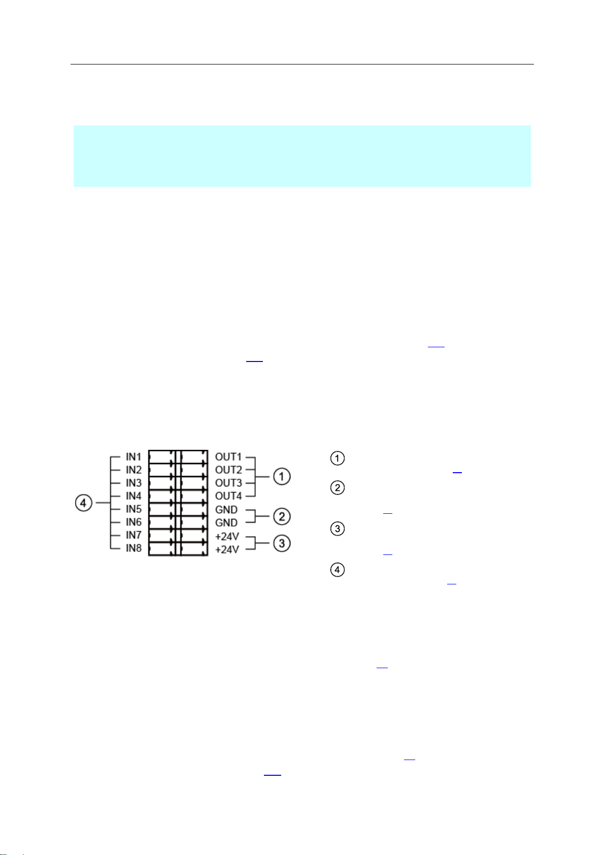
4x output channels (OUT1 .... OUT4)
→ Local outputs (→ S. 15)
2x voltage ground GND
→ Voltage source / voltage ground
(→ S. 14)
2x voltage source +24V
→ Voltage source / voltage ground
(→ S. 14)
8x input channels (IN1 ... IN8)
→ Local inputs (→ S. 14)
AC412S has the following interfaces.
>
Ethernet configuration interface
The configuration interface (X3) is located behind the front flap of the device. It allows the user to
access the following device functions:
web interface for device configuration and diagnosis
programming of the device-internal Standard-SPS and the fail-safe PLC using CODESYS
Configuration as fieldbus interface
Possible network topologies: → Configuration interface: connection concepts (→ S. 158)
Technical data: → Technical data (→ S. 153)
>
Local input/output interface
The local input/output interface (X4) is behind the front flap of the device. Safe and non-safe
peripherals without AS-i interface can be connected to the local inputs and outputs.
Connections of the local I/O interface:
42306
42193
42303
>
Voltage source / voltage ground
+24V and GND are used as voltage supply for the safety IO PCB of the safety module of AC412S.
Notes on the electrical connection: → Electrical connection (→ S. 29)
>
Local inputs
The local I/O interface provides 8 input channels for the connection of devices (e.g. sensors, switches,
light curtains). Each input channel can be used as safe or standard input. Configuration is effected via
the programming system CODESYS.
Connection of peripherals: → Connect devices to local I/O interface (→ S. 31)
Technical data: → Technical data (→ S. 153)
>
42272
42304

SmartPLC SafeLine with PROFIBUS slave interface
15
Local outputs
Min. configuration
Max. configuration
8 non-safe inputs
4 non-safe outputs
4 safe inputs, 2 channels (SIL3)
4 safe outputs, 1 channel (SIL3)
42291
The local I/O interface provides 4 output channels for the connection of devices (e.g. actuators,
relays). Each output channel can be used as safe or standard output. Configuration is effected via the
programming system CODESYS.
Notes on the connection of peripherals: → Connect devices to local I/O interface (→ S. 31)
Technical data: → Technical data (→ S. 153)
>
Possible combinations of input and output channels
42315
The inputs IN1...IN8 can be configured both as safe and non-safe inputs.
The outputs OUT1...OUT4 can be configured both as safe and non-safe outputs.
This permits the following minimum or maximum input and output combinations:
>
SD card slot
42194
The SD card slot (X5) is located behind the front flap of the device. The following actions can be
performed with an SD card:
Save and restore the device configuration
Storage medium for access to Standard-SPS
Technical data: → Technical data (→ S. 153)
>
PROFIBUS fieldbus interface
The device communicates with the higher-level control instance of the PROFIBUS network via the
PROFIBUS interface (X6).
Notes regarding connetion concepts: → Configuration interface: connection concepts (→ S. 158)
Technical data: → Technical data (→ S. 153)
41428
SmartPLC SafeLine with PROFIBUS slave interface
16
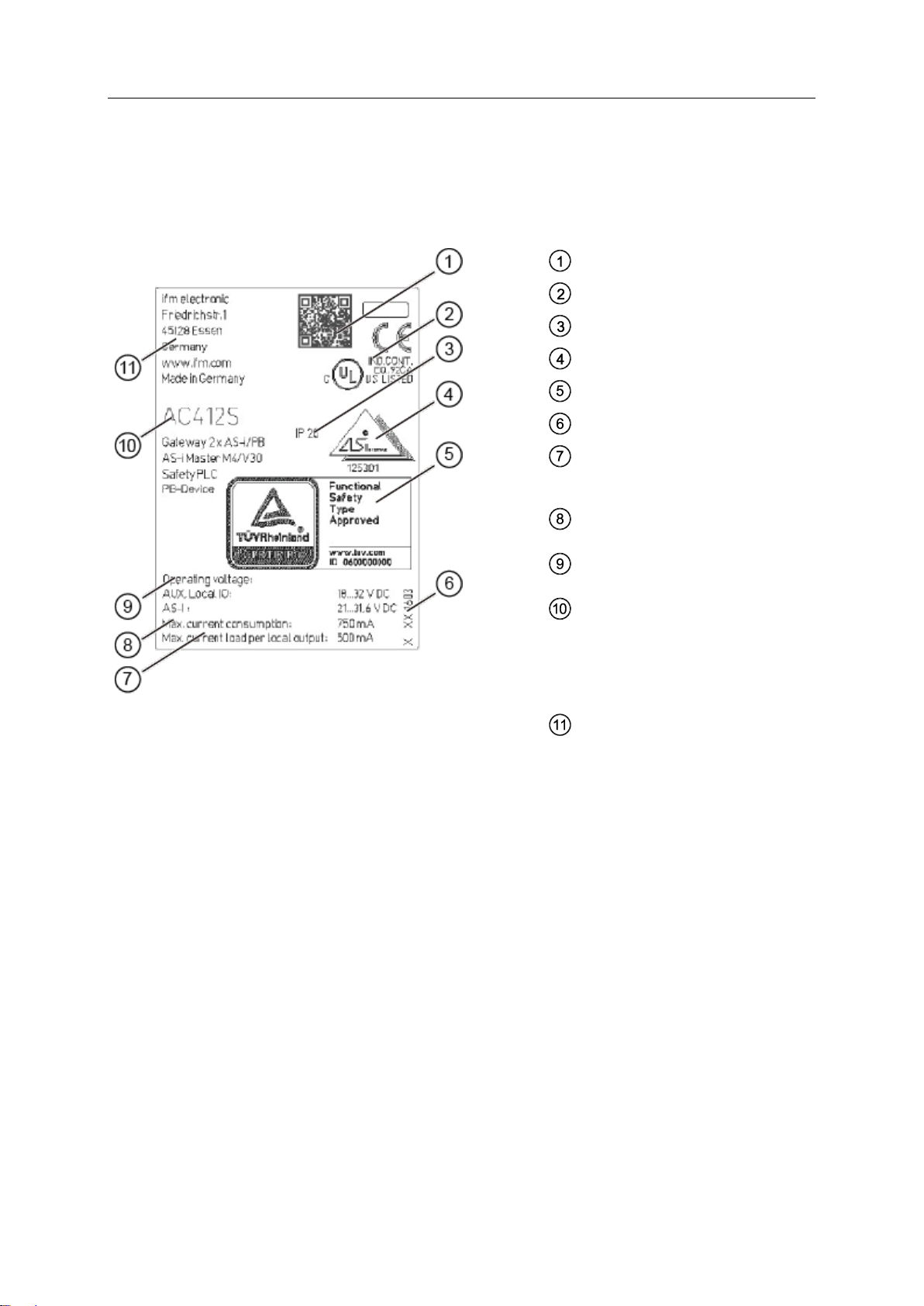
3.2.5 Type label
QR code for product website
CE/cULus marking
Protection class
AS-i certification
TÜV certification
Hardware version
Operating voltage for
– Aux / local IO PCB
– AS-i
max. current consumption of the
device
max. load per output channel of the
local I/O interface
Type designation incl. device
functionality
– number of AS-i fieldbus gateways
– classification of the AS-i masters
– fail-safe PLC
– fieldbus
Manufacturer identification
The type label is on the right housing side of the device. It provides the following information:
42274
>
3.2.6 Required accessories
To be able to operate the device in a sensible way you need the following accessories (not supplied
with the device):
Depending on the selected voltage supply ( Operating instructions) you need:
a power supply for the 24 V power supply (e.g. art. no. DN3011)
for each AS-i master one AS-i power supply each (e.g. art. no. AC1236)
a data decoupling module AC1250 (accessory, optional)
Fail-safe and standard AS-i slaves
Fail-safe and standard devices for connecting with the local I/O interface
42259

SmartPLC SafeLine with PROFIBUS slave interface
17
3.3 Hardware
Content
Safety architecture............................................................................................................................... 18
Operating states of AC412S .............................................................................................................. 22
Monitoring and securing mechanisms ................................................................................................. 23
Error detection and processing ........................................................................................................... 23
42223

SmartPLC SafeLine with PROFIBUS slave interface
18
3.3.1 Safety architecture
Content
System architecture ............................................................................................................................. 18
Process safety time ............................................................................................................................. 21
The reachable characteristic safety values of the automation system implemented with
AC412S depend on the following components:
Safety classification of the peripherals installed at the local I/O interface (→Supported device
types (→ S. 32))
Safety classification of the installed safe AS-i slaves
>
42266
System architecture
42268
The hardware structure of the safety module of AC412S corresponds to the implementation to DIN EN
ISO 13849-1:2008, IEC 62061:2010 and IEC61508:2010 with a two-channel architecture with
hardware fault tolerance (HFT = 1).
The device achieves the following characteristic safety values:
SIL 3 / SIL CL 3 referred to IEC 61508:2010 and IEC 62061:2010
Performance Level e EN ISO 13849-1:2008)
Category 4 (EN ISO 13849-1:2008)
SmartPLC SafeLine with PROFIBUS slave interface
19
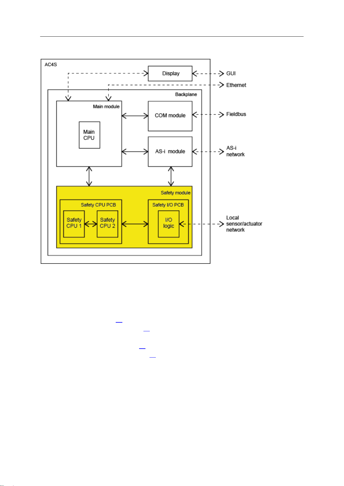
AC412S has the following system architecture:
>
Main module
42292
The main module is the central component of AC412S. It contains the recovery system and the
firmware of the device and controls the communication between the individual system components via
the backplane. The main module has interfaces to the following components:
Display (→ Display (→ S. 19))
COM module (→ COM module (→ S. 20))
Ethernet configuration interface
AS-i module (→ AS-i module (→ S. 20))
Safety module (→ Safety module (→ S. 20))
>
Display
42230
The display is the graphic user interface of AC412S via which the user can configure and diagnose the
device. The display exchanges the resulting data with the main module.

SmartPLC SafeLine with PROFIBUS slave interface
20
COM module
42210
The COM module provides the PROFIBUS functionality of AC412S. This comprises the PROFIBUS
connection and the necessary firmware. The COM module receives the fieldbus data from the main
module via an interface and transfers it to the fieldbus. Simultaneously it receives data from the
fieldbus and transfers it to the main module for further processing.
>
AS-i module
42242
The AS-i module provides the AS-i functionality of AC412S such as receiving, evaluating and
transmitting AS-i telegrams without any logical preprocessing. It contains 2 AS-i masters controlling 2
separate AS-i circuits.
The following number of AS-i slaves can be connected to each AS-i master:
up to 62 non safe AS-i slaves or
up to 31 safe AS-i input slaves or
up to 15 AS-i control slaves to control safe AS-i output slaves
The AS-i module exchanges the data of the safe AS-i slaves with the safety module via the backplane.
All AS-i data is provided to the main module for representation on the display.
>
Safety module
42251
The safety module contains the safety-related hardware of AC412S. The architecture of the safety
module provides the following structural features:
1oo2 hardware architecture (1 out of 2 architecture)
2-channel structure with separate diagnostics in both channels
2-channel safe inputs selectable
1-channel and 2-channel safe outputs selectable
Built-in tests on both safe processing units (safety CPU 1/2)
Hardware failure tolerance (HFT) = 1
The safety module consists of the following components:
Safety CPU PCB with 2 processors for the control technology signal processing (safety CPU1/2)
Safety I/O PCB with a separate voltage supply for the local I/O interface
Both PCBs are separated from each other galvanically. They are supplied from separate voltage
sources.
Both safety CPUs have separate watchdogs and reset circuits. They are interconnected via cross
communication.
Both PCBs are interconnected via a serial interface for bidirectional data exchange.
The safety module has interfaces to the main module and the AS-i module.

SmartPLC SafeLine with PROFIBUS slave interface
21
Process safety time
► When setting up the safety function, also take into account the process safety time of the
application!
► Take into account other potential delays caused by upstream and downstream
components (sensors, actuators) for time-related considerations. These times extend the
response time for safety-related faults.
► Process safety time of the other components of the safety function: the manufacturers’
data sheets
In the following cases a single fault cannot lead to a hazardous situation:
if the safe state is assumed
if the fault detection and the reaction to the fault happen within the process safety time
42313
The process safety time depends on the source and the objective of the request, the signal processing
and the transmission length.
If the safety time is shorter than the process safety time required by the safety function of the plant, a
single fault can in the worst case lead to a faulty output signal for a short time but not to a loss of the
safety function.
A loss of the safety function can only occur if the faulty signal cannot be corrected within the process
safety time.
SmartPLC SafeLine with PROFIBUS slave interface
22
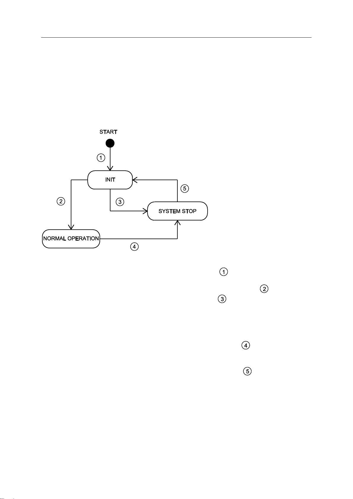
3.3.2 Operating states of AC412S
AC412S has the following operating states:
INIT
NORMAL OPERATION
SYSTEM STOP
Below the state chart:
42321
INIT
After the start the device automatically goes into the INIT state ( ). In the INIT state the device
undergoes the different hardware and integration tests (PBIT = Power-up Built-In Test). If the PBIT
test is successfully passed, the device takes the state NORMAL OPERATION ( ). If the PBIT
test is not passed, the device passes into the SYSTEM STOP ( ).
NORMAL OPERATION
In NORMAL OPERATION the device of Standard-SPS and the fail-safe PLC provides a working
environment. The states and the operation modes of the PLC applications are valid (see
programming manual). Simultaneously and irrespective of the processing of the PLC applications
the device continuously undergoes different hardware tests (CBIT = continuous built-in test). If this
CBIT test is not passed, the device goes into the SYSTEM STOP state ( ).
SYSTEM STOP
In SYSTEM STOP the device is in the safe state. To leave the SYSTEM STOP state the operator
has to carry out a power-on reset. The device changes to the INIT state ( ).

SmartPLC SafeLine with PROFIBUS slave interface
23
3.3.3 Monitoring and securing mechanisms
>
System start / power on reset
When the voltage supply has been applied, the safety module of AC412S automatically undergoes a
power-on built-in test (PBIT). The PBIT consists of the following routines:
Test and installation of the safety-relevant hardware modules
Test of the program, configuration and user data in SDRAM (CRC test)
If at least one of these partial tests is failed, the system reacts as follows:
The safety module goes into the safe state
The transition from the fail-safe PLC to the safe operation is prevented
An error message is provided in the online support centre (OSC) of the device
>
Normal operation
During normal operation the safety module of AC412S continuously undergoes a continuous built-in
test (CBIT). The CBIT detects accidental hardware errors. It monitors all safety-relevant hardware
modules. The CBIT consists of the following routines:
Monitor the safety-relevant hardware modules with the required DC
Monitor all diagnostic data that is relevant for the safe functions
Monitor the program process
Depending on the error class the device triggers certain measures (→Error classes (→ S. 23)).
>
42296
42276
42297
3.3.4 Error detection and processing
>
Error classes
AC412S recognises the following error classes:
>
Fatal error
The following errors are classified as fatal errors:
error in the device (temperature exceeded, soiling)
error in the channels
Response to fatal errors:
The safety module goes into the safe state (→Safe state (→ S. 25))
42221
42218
42222

SmartPLC SafeLine with PROFIBUS slave interface
24
Serious error
42252
Following errors are classified as serious errors:
Errors occurring in the periphery which do not affect the processing logic of the device
Response to serious errors:
The safety module goes into the safe state (→Safe state (→ S. 25))
>
Exception errors
42225
An exception error occurs when the device software is in a non foreseen state.
Response to exception errors:
The safety module goes into the safe state (→Safe state (→ S. 25))
>
Scheduling errors
42254
The following errors are classified as scheduling errors:
Errors in the correct processing of the different tasks in the course of which the operating system
cannot make a task change any more so that the watchdog is triggered.
Response to scheduling errors:
All output channels of the local I/O interface go into the default state (= switched off)
All safe output slaves stop sending code sequences
Restart disable of the fail-safe PLC
>
Error message
AC412S signals occurring errors via the following mechanisms:
status LED (→Status LED (→ S. 145))
online support Centre (→Online Support Centre (OSC) (→ S. 148))
42224

SmartPLC SafeLine with PROFIBUS slave interface
25
Safe state
All non safety-relevant functions of the basic device continue to be available in the safe state.
42258
The safety module of AC412S is always in the safe state. Exceptions are the following operating
states of the fail-safe PLC:
debug operation
download operation
safe operation
If a fatal, serious or exception error occurs during these operating states, the safety module of
AC412S goes into the safe state.
The safe state is characterised by the following features:
All safe output channels of the local I/O interface are already power-free
All safe AS-i control slaves have stopped sending code sequences
the fail-safe PLC is in the STOP mode
the cyclic data transfer between safety module and basic device is interrupted
the data packages of the safe cross communication between the two safety CPUs are filled with
zero sequences and marked as "invalid"
the basic device detects that the safety module is in the safe state and provides this information in
the OSC and on the PROFIBUS and configuration interface
>
Reset error
All error states (→Error classes (→ S. 23)) can only be exited using one of the following measures.
► Reboot the device (power-on reset)
42257
SmartPLC SafeLine with PROFIBUS slave interface
26
3.4 Software
Content
Software modules of the device .......................................................................................................... 26
Safety functions ................................................................................................................................... 26
Certified software components for safe applications ........................................................................... 27
Software modules
Description
Recovery system
Environment for the firmware installation
Firmware
Firmware of AC412S
CODESYS standard runtime system
(Standard-SPS)
Runtime environment for the execution of CODESYS applications to IEC 61131
CODESYS safety runtime system (failsafe PLC)
Certified runtime environment for the execution of safe CODESYS applications
Standard application
CODESYS application for Standard-SPS
Safe application
CODESYS application for fail-safe PLC (= safety function)
The user is responsible for setting the safe function of the application (= safe application). If
necessary, he must also obtain an approval from the supervisory and test organisations
according to the national regulations.
AC412S provides the programmer with a safe environment which is suited for the execution
of a safe application to SIL3. The user is responsible for programming the safe application.
>
3.4.1 Software modules of the device
AC412S has the following software modules:
>
3.4.2 Safety functions
AC412S provides the following safety functions:
Freely programmable fail-safe PLC
Safe reading of local digital inputs and linking via the fail-safe PLC
Safe control of local digital outputs via the fail-safe PLC
Safe reading of safe AS-i input slaves and linking via the fail-safe PLC
Control of safe AS-i output slaves via the fail-safe PLC
Safe data transfer between min. 2 AC412S
Safe data transfer from and to EtherCAT slaves (FSoE)
42280
42281
42262

SmartPLC SafeLine with PROFIBUS slave interface
27
3.4.3 Certified software components for safe applications
Information about device-specific software components and about how to program StandardSPS and the fail-safe PLC: → Programming manual fail-safe SmartPLC AC4S"
42207
To program safe applications for AC412S ifm electronic provides certified software components for the
programming environment CODESYS safety 3.5. In addition, the user can use the function libraries
supplied with CODESYS safety.

SmartPLC SafeLine with PROFIBUS slave interface
28
4 Mounting
Content
Install device ...................................................................................................................................... 28
Ensure a condensation-free environment. Avoid excessive dust, vibration and shock. The air
circulation through the vents must not be impeded. Installation in environments with ionising
radiation is not permitted.
Avoid installation in direct vicinity of frequency inverters or other interfering sources.
>
34058
4.1 Install device
42302
The device must only be installed, connected and put into operation by a qualified electrician as the
safe function of the device and machinery is only guaranteed when installation is correctly carried out.
The installation and connection must comply with the applicable national and international standards.
Responsibility lies with the person installing the device.
► Fix the device onto a 35 mm raised rail.
► Vertical installation (upright).
► Adhere to a minimum distance of 30 mm between the ventilation holes (perforated sheet) and
other parts.
► Maximum operating distance: 2000 m above sea level
► The protection rating of the device is IP 20. The installation must take place in a control cabinet
with at least IP 54 protection.
► Lay the cables in a cable duct.
► Keep the installation space of the device free from electrically-conductive particles.
SmartPLC SafeLine with PROFIBUS slave interface
29
5 Electrical connection
Content
Wiring .................................................................................................................................................. 29
Connect the supply voltage ................................................................................................................. 29
Connect devices to local I/O interface ................................................................................................. 31
The device must be connected by a qualified electrician.
► Disconnect power before connecting the device.
► Observe the national and international regulations for the installation of electrical
equipment.
► Connect the device as indicated on the terminals.
► Ensure an electrical connection between the AC412S (X1, terminal FE) and the ground
of the installation.
Terminal X1
Pin
Description
AS-i 2 +
1
AS-i + for AS-i line 2
AS-i 2 -
2
AS-i - for AS-i line 2
AS-i 1 +
3
AS-i + for AS-i line 1
AS-i 1 -
4
AS-i - for AS-i line 1
FE
5
Functional earth
6
Not connected
Terminal X2
Pin
Description
24 V
1
+24 V device supply
GND
2
GND
Terminal X4
Pin
Description
1...8
IN1...IN8
9...12
OUT1...OUT4
13,14
GND 15,16
+24 V power supply Safe-IO module
Terminal X3, X8
Configuration interfaces
Socket X6
EtherCAT interface 2 (OUT)
Socket X7
EtherCAT interface 1 (IN)
5.1 Wiring
42226
42273
A fixed terminal assignment is mandatory for the fail-safe inputs (IN 1...8) → Connect sensors / actuators
(→ S. 43)
>
5.2 Connect the supply voltage
Supply the device with one of the following versions.
42212

SmartPLC SafeLine with PROFIBUS slave interface
30
>
Power must be applied simultaneously to the Safe_IO module (terminal X4) and to the
device supply (terminal X2).
24 V device supply
Connect the pins 24 V and 0 V of terminal X2 to a 24 V DC power supply (18...32 V
SELV/PELV).
24 V Safe-IO power supply
Connect the pins 24 V and GND of terminal X4 to a 24 V DC power supply (18...32 V
SELV/PELV).
5.2.1 Standard configuration: 24 V power supply and AS-i power supply/supplies
42279
► Connect the supply voltage inputs of the device to the power supply intended for this purpose.
AS-i bus 1
Connect the AS-i 1+ and AS-i 1- pins of terminal X1 to the AS-i power supply (e.g. AC1254) of the
first AS-i bus.
AS-i bus 2
Connect the AS-i 2+ and AS-i 2- pins of terminal X1 to the AS-i power supply (e.g. AC1254) of the
second AS-i bus.
► Ensure a low-resistance connection of the symmetry point of the device (terminal X1, pin 5 FE) to
the ground of the installation.
► For the 24 V power supply (device, Safe-IO), select a power supply which supplies an output
current of at least 3 A.
► The cable length of the DC supply between power supply and AC412S is to be limited to max. 3
m.
The power supplies used must meet the standard DIN EN 60950-1 for SELV/PELV.
 Loading...