

IFM Electronic AC3218, AC3219 Operating Instructions Manual
Operating instructions
AS-i SmartLine module
AC3218
AC3219
UK
80255917/00 01/2017

Contents
1 Preliminary note ��������������������������������������������������������������������������������������������������� 3
1�1 Explanation of symbols ����������������������������������������������������������������������������������3
2 Safety instructions �����������������������������������������������������������������������������������������������3
3 Functions and features ����������������������������������������������������������������������������������������4
4 Addressing ����������������������������������������������������������������������������������������������������������� 4
4�1 Addressing with the AC1154 addressing unit�������������������������������������������������4
5 Installation������������������������������������������������������������������������������������������������������������5
5�1 Installation of the device ��������������������������������������������������������������������������������5
5�2 Removal of the device �����������������������������������������������������������������������������������5
6 Electrical connection �������������������������������������������������������������������������������������������� 6
6�1 Wiring�������������������������������������������������������������������������������������������������������������6
6�2 Connection analogue module AC3218 (0���20 mA) ���������������������������������������7
6�2�1 Connection of an actuator without separate voltage supply ����������������� 7
6�2�2 Connection of an actuator with intrinsic supply �����������������������������������7
6�2�3 Connection of an actuator with separate 24 V supply ��������������������������8
6�2�4 Electrical connection 0 V terminal ��������������������������������������������������������8
6�3 Connection analogue module AC3219 (0���10 V) ������������������������������������������9
6�3�1 Connection of an actuator with intrinsic supply ������������������������������������9
6�3�2 Connection of an actuator with separate 24 V supply ����������������������10
7 Parameter setting ����������������������������������������������������������������������������������������������10
8 Measuring range ������������������������������������������������������������������������������������������������ 11
8�1 Analogue module AC3218 ��������������������������������������������������������������������������� 11
8�2 Analogue module AC3219 ��������������������������������������������������������������������������� 11
8�3 Transmission time of the analogue values �������������������������������������������������� 11
9 Operation ����������������������������������������������������������������������������������������������������������� 12
10 Maintenance, repair, disposal �������������������������������������������������������������������������� 12
10�1 Maintenance ����������������������������������������������������������������������������������������������12
10�2 Cleaning of the housing surface ����������������������������������������������������������������12
10�3 Repair ��������������������������������������������������������������������������������������������������������12
10�4 Disposal ����������������������������������������������������������������������������������������������������� 12
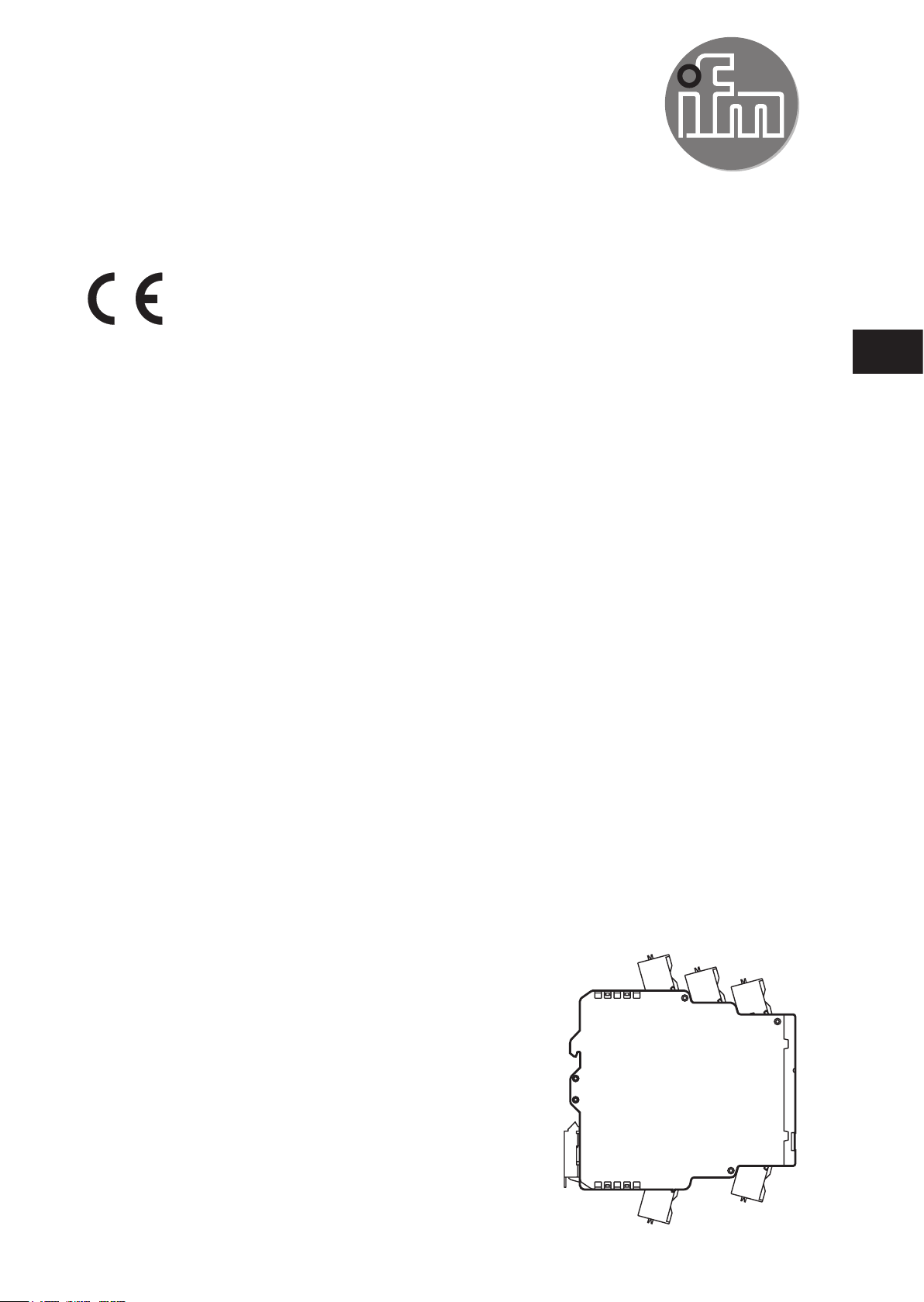
11 Scale drawing ��������������������������������������������������������������������������������������������������13
2

1 Preliminary note
Technical data, approvals, accessories and further information at
www�ifm�com�
1.1 Explanation of symbols
► Instructions
> Reaction, result
→ Cross-reference
Important note
Non-compliance may result in malfunction or interference�
Information
Supplementary note�
UK
2 Safety instructions
• Read this document before setting up the product and keep it during the entire
service life�
• The product must be suitable for the corresponding applications and
environmental conditions without any restrictions�
• Only use the product for its intended purpose (→ Functions and features).
• If the operating instructions or the technical data are not adhered to, personal
injury and/or damage to property may occur�
• The manufacturer assumes no liability or warranty for any consequences
caused by tampering with the product or incorrect use by the operator�
• Installation, electrical connection, set-up, operation and maintenance of the unit
must be carried out by qualified personnel authorised by the machine operator�
• Protect units and cables against damage�
3

3 Functions and features
The slave receives data via the AS-Interface and converts them into analogue
output signals� The AS-i module operates as a slave with bidirectional data
transfer in the AS-i network�
The data transfer from the host to the slave is asynchronous according to the AS-i
profile S-7�3 and the AS-i specification V2�11�
• The slave can be operated in conjunction with a version 2�11 master or higher
(master profile M3 or M4)�
• Current output 0��20 mA (AC3218) or voltage output 0���10 V (AC3219)
• R
for current output 600 Ω (AC3218)
max
R
for voltage output > 1 kΩ (AC3219)
min
• AS-i profile S-7�3�6
• Maximum number of modules per AS-i system: 31
• Conversion time (digital - analogue) in the slave with four channels: < 1 ms
• Actuator supply from AS-i (max� 90mA) or external 24 V PELV voltage source
(the supply is selected automatically as soon as an external voltage is applied)
• 16 bits / 1 µA (AC3218) or 16 bits / 1 mV (AC3219)
• The actuators are connected via COMBICON terminals
4 Addressing
► Assign a free address between 1 and 31�
The address is set to 0 at the factory�
4.1 Addressing with the AC1154 addressing unit
► When mounted and wired the module can be addressed with the addressing
cable (E70213) via the integrated addressing interface�
No addressing via the addressing socket while live�
4
 Loading...