

Page 1
Operating instructions
AS-i SmartLine module
AC3216
AC3217
UK
80255918/00 01/2017
Page 2

Contents
1 Preliminary note ��������������������������������������������������������������������������������������������������� 3
1�1 Explanation of symbols ����������������������������������������������������������������������������������3
2 Safety instructions �����������������������������������������������������������������������������������������������3
3 Functions and features ����������������������������������������������������������������������������������������4
4 Addressing ����������������������������������������������������������������������������������������������������������� 4
4�1 Addressing with the AC1154 addressing unit�������������������������������������������������4
5 Installation������������������������������������������������������������������������������������������������������������5
5�1 Installation of the device ��������������������������������������������������������������������������������5
5�2 Removal of the device �����������������������������������������������������������������������������������6
6 Electrical connection �������������������������������������������������������������������������������������������� 6
6�1 Wiring�������������������������������������������������������������������������������������������������������������7
6�1�1 Connection of a 2-wire sensor �������������������������������������������������������������� 7
6�1�2 Connection of a 3-wire sensor �������������������������������������������������������������� 8
6�1�3 Connection of a 4-wire sensor �������������������������������������������������������������� 8
6�1�4 Connection of an analogue sensor with intrinsic supply ���������������������� 9
7 Parameter setting ������������������������������������������������������������������������������������������������9
8 Measuring range ������������������������������������������������������������������������������������������������ 10
8�1 Analogue module AC3216 ���������������������������������������������������������������������������10
8�2 Analogue module AC3217 ���������������������������������������������������������������������������10
8�3 Transmission time of the analogue values ��������������������������������������������������10
9 Operation ����������������������������������������������������������������������������������������������������������� 11
9�1 LED display AC3216 ������������������������������������������������������������������������������������ 11
9�2 LED display AC3217 ������������������������������������������������������������������������������������ 12
10 Maintenance, repair, disposal �������������������������������������������������������������������������� 12
10�1 Maintenance ����������������������������������������������������������������������������������������������12
10�2 Cleaning of the housing surface ����������������������������������������������������������������12
10�3 Repair ��������������������������������������������������������������������������������������������������������13
10�4 Disposal ����������������������������������������������������������������������������������������������������� 13
11 Scale drawing ��������������������������������������������������������������������������������������������������13
2
Page 3

1 Preliminary note
Technical data, approvals, accessories and further information at
www�ifm�com�
1.1 Explanation of symbols
► Instructions
> Reaction, result
→ Cross-reference
Important note
Non-compliance may result in malfunction or interference�
Information
Supplementary note�
UK
2 Safety instructions
• Read this document before setting up the product and keep it during the entire
service life�
• The product must be suitable for the corresponding applications and
environmental conditions without any restrictions�
• Only use the product for its intended purpose (→ Functions and features).
• If the operating instructions or the technical data are not adhered to, personal
injury and/or damage to property may occur�
• The manufacturer assumes no liability or warranty for any consequences
caused by tampering with the product or incorrect use by the operator�
• Installation, electrical connection, set-up, operation and maintenance of the unit
must be carried out by qualified personnel authorised by the machine operator�
• Protect units and cables against damage�
3
Page 4

3 Functions and features
The slave converts analogue input signals and transfers them to the AS-i master
via the AS-Interface� The AS-i module operates as a slave with bidirectional data
transfer in the AS-i network�
The data transfer from the host to the slave is asynchronous according to the AS-i
profile S-7�3 and the AS-i specification V2�11�
• The slave can be operated in conjunction with a version 2�11 master or higher
(master profile M3 or M4).
• Current measurement 4...20 mA (AC3216)
or voltage measurement 0...10 V (AC3217)
• R
current measurement < 50 Ω (AC3216)
i
Ri voltage measurement > 100 kΩ (AC3217)
• AS-i profile S-7�3�E
• Maximum number of modules per AS-i system: 31
• Conversion time (digital - analogue) in the slave
- for one channel: 20 ms
- for two channels: 120 ms
- for three channels: 180 ms
- for four channels: 240 ms
• Sensor supply from AS-i (max. 100 mA) or external 24 V PELV voltage source
(the external supply voltage is selected automatically as soon as an external
24 V voltage is applied)
• Resolution: 16 bits / 1 µA (AC3216) or 16 bits/1 mV (AC3217)
• Value range: 4000...20000 dec. (AC3216) or 0...10000 dec. (AC3217)
• The sensors are connected via COMBICON terminals
4 Addressing
► Assign a free address between 1 and 31�
The address is set to 0 at the factory�
4.1 Addressing with the AC1154 addressing unit
► When mounted and wired the module can be addressed with the addressing
cable (E70213) via the integrated addressing interface.
4
Page 5

No addressing via the addressing socket while live�
5 Installation
5.1 Installation of the device
► Install the device on a 35 mm DIN rail�
UK
► Leave enough space between the unit and the top and bottom of the control
cabinet to enable air circulation and to avoid excessive heating�
► Take into account the internal heating of all devices when mounting several
devices side by side and observe the environmental conditions for every
device�
5
Page 6

5.2 Removal of the device
6 Electrical connection
The unit must be connected by a qualified electrician�
The national and international regulations for the installation of electrical
equipment must be adhered to�
► Disconnect power�
► Connect the unit�
6
Page 7

6.1 Wiring
I+ sensor supply +24 V
C1���C4 analogue input current (AC3216)
V1���V4 analogue input voltage (AC3217)
I- sensor supply 0 V
AC3216 AC3217
I+
V1
I-
V2
V3
0V
I-
0V
I-
0V
I+
I+
I+
C1
C2
C3
I-
0V
I-
0V
I-
0V
I+
I+
0 V analogue input 0V
A+ AS-i +
A- AS-i -
E+ external sensor supply +24 V
E- external sensor supply 0 V
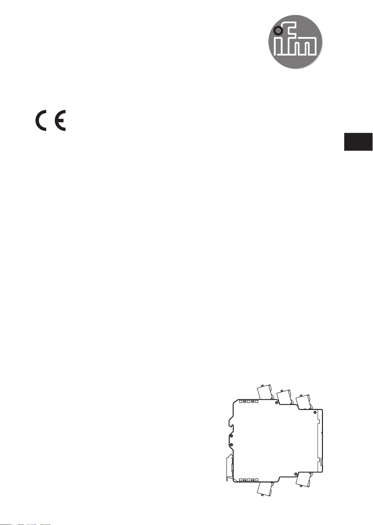
6.1.1 Connection of a 2-wire sensor
1
2
0VA+I-A-C4E+I+
E-
UK
0VA+I-A-V4E+I+
E-
C1 ... 4 (AC3216)
V1 ... 4 (AC3217)
0V
1: Analogue module
2: 2-wire sensor
I+
I-
+
-
A 2-wire sensor is connected via the
terminals I+ and C1...4 (AC3216) or
V1...2 (AC3217).
The terminals I- and 0V must be
connected to each other via a link�
7
Page 8
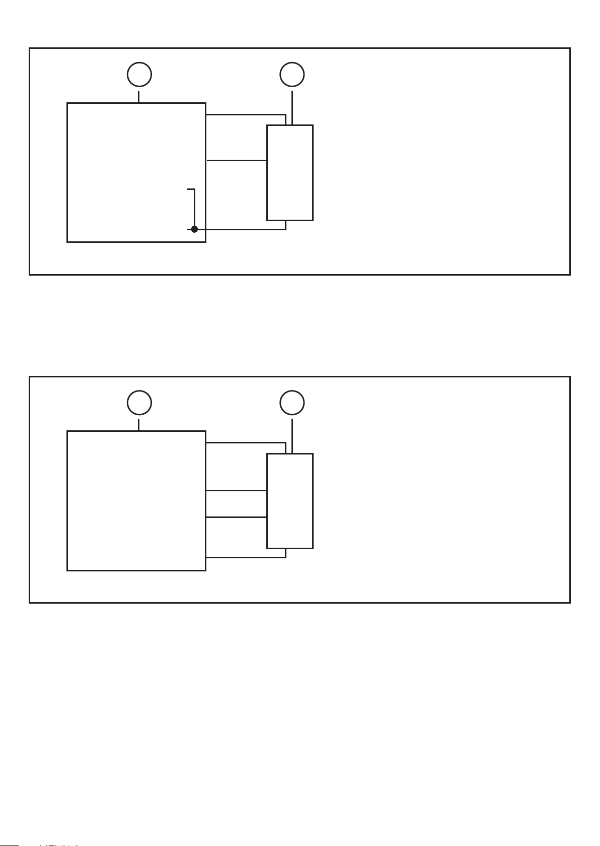
6.1.2 Connection of a 3-wire sensor
1
I+
2
U+
C1 ... 4 (AC3216)
V1 ... 4 (AC3217)
0V
I/U
U-
I-
1: Analogue module
2: 3-wire sensor
6.1.3 Connection of a 4-wire sensor
A 3-wire sensor is connected via the
terminals I+, I- and C1...4 (AC3216) or
V1...4 (AC3217).
The terminals I- and 0V must be
connected to each other via a link�
1
C1 ... 4 (AC3216)
V1 ... 4 (AC3217)
0V
1: Analogue module
2: 4-wire sensor
I+
I-
2
U+
I/U+
I/U+
U-
A 4-wire sensor is connected via the
terminals I+, I-, C1...4 (AC3216) or
V1...4 (AC3217) and 0 V.
8
Page 9

6.1.4 Connection of an analogue sensor with intrinsic supply
2
1
I+
C1 ... 4 (AC3216)
V1 ... 4 (AC3217)
0V
I-
1: Analogue module
2: Sensor with intrinsic supply
3: Supply PELV ungrounded
7 Parameter setting
Parameter bit
/ Designation
Description Comments
+
-
3
A sensor with intrinsic supply is
connected via the terminals C1���4
(AC3216) or V1...4 (AC3217) and
0 V�
UK
P0
Filter
P1, P2
Channel activation
1*
50 Hz filter active in the
A/D converter The 50 Hz filter applies to the whole
0*
60 Hz filter active in the
A/D converter
parameter bit analogue channel
P1 P2 1 2 3 4
0 0 on off off off
0 1 on on off off
1 0 on on on off
1 1 on on on on
of Europe
P3
Peripheral fault
1* peripheral fault active
0 peripheral fault not
active
* default setting
9
Page 10

8 Measuring range
► The measuring ranges, the states of the LEDs and their meaning are indicated
in the following tables�
8.1 Analogue module AC3216
Range
4...20 mA
< 1 mA 32767 7FFF flashing wire break
1 mA���3�999 mA 1000���3999 03E8���0F9F on below nominal
4 mA���20 mA 4000 ��� 20000 0FA0���4E20 on nominal range
20�001 mA���23 mA 20001���23000 4E21���59D8 on above nominal
> 23 mA 32767 7FFF flashing overflow
Units
dec.
Units
hex.
LED
analogue
Meaning
range
range
8.2 Analogue module AC3217
Range
0...10 V
< 0 V 0000 0000 on outside range
0 ���10 V 0000���10000 0000���2710 on nominal range
10�001���11�5 V 10001���11500 2711���2CEC on above nominal
> 11�5 V 32767 7FFF flashing overflow
Units
dec.
Units
hex.
LED
analogue
Meaning
range
8.3 Transmission time of the analogue values
The transmission time of the analogue values depends on the conversion
time of the analogue signals into digital signals in the AS-i module and on the
transmission time via the AS-Interface�
The conversion time per analogue input signal is 60 ms� But if only channel 1 is
used, i�e� all other channels are deactivated via the parameter bits P1 and P2, the
conversion time for this channel is only 20 ms�
10
Page 11

The transmission time of the 4 16-bit values via the AS-interface ideally is 7
AS-i cycles per value� For a cycle time of 5 ms per AS-i cycle this results in a
transmission time of 4 x 7 x 5 ms = 140 ms via the AS-Interface�
If the channels 2 to 4 are deactivated, the transmission via the AS-Interface for
one channel requires 7 AS-i cycles� For a cycle time of 5 ms per AS-i cycle this
results in a transmission time of 1 x 7 x 5 ms = 35 ms via the AS-Interface�
Thus the total transmission time for 4 analogue values ideally is 240 ms
(conversion time) + 140 ms (transmission time) = 380 ms. If channels 2 to 4 are
UK
deactivated, the transmission time ideally is 20 ms + 35 ms = 55 ms�
9 Operation
► Check the safe functioning of the unit�
9.1 LED display AC3216
LED AS-i green lights AS-i voltage supply OK
LED AUX green lights external voltage supply 24 V OK
LEDs I1���I4 yellow light analogue signal in the measuring range
LEDs I1���I4 yellow flash analogue signal outside the measuring range, no
sensor connected or wire break
LEDs I2���I4 yellow off no sensor connected
(at least one LED flashes, because not all channels
can be deactivated via the parameter bit P1/P2)
(channel activation)
(channel 1 is always activated)
LED FAULT red lights AS-i communication error,
e� g� slave address 0
LED FAULT red flashes Peripheral fault
A peripheral fault is displayed, if
- at least one of the analogue signals is outside the
value range
- nothing is connected to at least one analogue
channel although the respective channel is
enabled
- if a wire break occurred
11
Page 12

LED yellow DIAG
internal diagnostics
- DIAG lights
- DIAG flashes
- DIAG off
- no fault
- internal fault (replace module)
- internal fault (replace module)
9.2 LED display AC3217
LED AS-i green lights AS-i voltage supply OK
LED AUX green lights External voltage supply 24 V OK
LEDs I1���I4 yellow light The respective channel is activated
Analogue signal in the measuring range or no sensor
connected (it cannot be differentiated whether
the 0 V signal is applied or whether no sensor is
connected)
(channel 1 is always enabled)
LEDs I1���I4 yellow flash Analogue signal outside the measuring range
(overflow)
LEDs I2���I4 yellow off The respective channel is not activated
LED FAULT red lights AS-i communication error,
e� g� slave address 0
LED FAULT red flashes Peripheral fault
A peripheral fault is indicated if at least one of the
analogue signals is outside the value range
LED yellow DIAG
- DIAG lights
- DIAG flashes
- DIAG off
Internal diagnostics
- no fault
- internal fault (replace module)
- internal fault (replace module)
10 Maintenance, repair, disposal
10.1 Maintenance
The unit is maintenance-free�
10.2 Cleaning of the housing surface
► Disconnect the device�
► Clean the device from dirt using a soft, chemically untreated and dry cloth�
12
Page 13

Micro-fibre cloths without chemical additives are recommended�
10.3 Repair
► The device must only be repaired by the manufacturer�
10.4 Disposal
► Dispose of the device in accordance with the national environmental
regulations�
11 Scale drawing
25,4
LED
93
126
UK
108
35
13
 Loading...