

IFM Electronic AC2630, AC2636, AC2637, AC2638, AC2631 Device Manual
...
Device manual
Field modules DP
AC2630 / AC2631 / AC2634
AC2636 / AC2637 / AC2638
UK
7390983 / 00 03 / 2013

Field modules DP
Contents
1 Preliminary note � � � � � � � � � � � � � � � � � � � � � � � � � � � � � � � � � � � � � � � � � � � � � � � � � 4
2 Safety instructions � � � � � � � � � � � � � � � � � � � � � � � � � � � � � � � � � � � � � � � � � � � � � � � 5
3 Documentation� � � � � � � � � � � � � � � � � � � � � � � � � � � � � � � � � � � � � � � � � � � � � � � � � � 6
3�1 Firmware and hardware status� � � � � � � � � � � � � � � � � � � � � � � � � � � � � � � � � � 6
3�1�1 Downward compatibility � � � � � � � � � � � � � � � � � � � � � � � � � � � � � � � � � � � 6
4 Connections � � � � � � � � � � � � � � � � � � � � � � � � � � � � � � � � � � � � � � � � � � � � � � � � � � � � 7
4�1 Fieldbus connection � � � � � � � � � � � � � � � � � � � � � � � � � � � � � � � � � � � � � � � � � � 7
4�2 Fieldbus termination � � � � � � � � � � � � � � � � � � � � � � � � � � � � � � � � � � � � � � � � � � 7
4�3 Nominal current consumption of modules connected to PROFIBUS-DP� � 7
4�4 Connection to a Siemens PLC type S7-300� � � � � � � � � � � � � � � � � � � � � � � � 8
4�4�1 Importing the GSD file � � � � � � � � � � � � � � � � � � � � � � � � � � � � � � � � � � � � 8
4�5 Selection of modules as slaves � � � � � � � � � � � � � � � � � � � � � � � � � � � � � � � � 12
5 Data mapping of the modules� � � � � � � � � � � � � � � � � � � � � � � � � � � � � � � � � � � � � � 13
5�1 Data mapping: Stand-alone and extension modules � � � � � � � � � � � � � � � � 13
5�1�1 Digital input modules � � � � � � � � � � � � � � � � � � � � � � � � � � � � � � � � � � � � 13
5�1�2 Digital output modules � � � � � � � � � � � � � � � � � � � � � � � � � � � � � � � � � � � 13
5�1�3 Digital combined modules � � � � � � � � � � � � � � � � � � � � � � � � � � � � � � � � 13
5�1�4 Analogue input modules� � � � � � � � � � � � � � � � � � � � � � � � � � � � � � � � � � 14
5�1�5 Analogue output modules � � � � � � � � � � � � � � � � � � � � � � � � � � � � � � � � 14
6 Error handling and diagnosis � � � � � � � � � � � � � � � � � � � � � � � � � � � � � � � � � � � � � � 15
6�1 Error handling via LEDs � � � � � � � � � � � � � � � � � � � � � � � � � � � � � � � � � � � � � � 15
6�1�1 Flash codes � � � � � � � � � � � � � � � � � � � � � � � � � � � � � � � � � � � � � � � � � � � 15
6�1�2 Diagnostic LEDs for PROFIBUS � � � � � � � � � � � � � � � � � � � � � � � � � � � 16
6�1�3 Error causes� � � � � � � � � � � � � � � � � � � � � � � � � � � � � � � � � � � � � � � � � � � 17
6�2 Error diagnosis via software � � � � � � � � � � � � � � � � � � � � � � � � � � � � � � � � � � � 17
6�2�1 General structure of the diagnostic messages� � � � � � � � � � � � � � � � � 18
6�2�2 Diagnostic message of the stand-alone modules � � � � � � � � � � � � � � 19
7 ifm Profibus DP modules � � � � � � � � � � � � � � � � � � � � � � � � � � � � � � � � � � � � � � � � � 21
7�1 General technical information� � � � � � � � � � � � � � � � � � � � � � � � � � � � � � � � � � 21
7�2 Supply voltage � � � � � � � � � � � � � � � � � � � � � � � � � � � � � � � � � � � � � � � � � � � � � 21
7�2�1 Operating voltage � � � � � � � � � � � � � � � � � � � � � � � � � � � � � � � � � � � � � � 21
7�2�2 Load voltage � � � � � � � � � � � � � � � � � � � � � � � � � � � � � � � � � � � � � � � � � � 21
7�3 Nominal current consumption of the modules � � � � � � � � � � � � � � � � � � � � � 22
7�4 Electrical isolation � � � � � � � � � � � � � � � � � � � � � � � � � � � � � � � � � � � � � � � � � � 22
7�4�1 Digital modules � � � � � � � � � � � � � � � � � � � � � � � � � � � � � � � � � � � � � � � � 22
7�4�2 Analogue modules � � � � � � � � � � � � � � � � � � � � � � � � � � � � � � � � � � � � � 22
7�5 Incoming line and power supply � � � � � � � � � � � � � � � � � � � � � � � � � � � � � � � � 22
7�5�1 Power loss of power cable � � � � � � � � � � � � � � � � � � � � � � � � � � � � � � � � 23
7�6 Start-up behaviour of the modules � � � � � � � � � � � � � � � � � � � � � � � � � � � � � � 23
7�7 Scale drawing� � � � � � � � � � � � � � � � � � � � � � � � � � � � � � � � � � � � � � � � � � � � � � 24
8 Devices� � � � � � � � � � � � � � � � � � � � � � � � � � � � � � � � � � � � � � � � � � � � � � � � � � � � � � � 25
2

Field modules DP
8�1 Technical data � � � � � � � � � � � � � � � � � � � � � � � � � � � � � � � � � � � � � � � � � � � � � 25
8�2 Digital stand-alone modules � � � � � � � � � � � � � � � � � � � � � � � � � � � � � � � � � � � 25
8�2�1 AC2630 FieldModuleDP 4x2DI M12 � � � � � � � � � � � � � � � � � � � � � � � � 25
8�2�2 AC2631 FieldModuleDP 2x2DI 2x2DO M12 � � � � � � � � � � � � � � � � � � 25
8�3 Analogue input modules � � � � � � � � � � � � � � � � � � � � � � � � � � � � � � � � � � � � � � 25
8�3�1 AC2638 FieldModuleDP 4AI (V) M12� � � � � � � � � � � � � � � � � � � � � � � � 25
8�3�2 AC2636 FieldModuleDP 4AI (C) M12 � � � � � � � � � � � � � � � � � � � � � � � 26
8�3�3 AC2634 FieldModuleDP 4AI (PT100) M12 � � � � � � � � � � � � � � � � � � � 29
8�3�4 AC2637 FieldModuleDP 4AO (C) M12� � � � � � � � � � � � � � � � � � � � � � � 32
UK
This document is the original instructions�
3
Field modules DP
1 Preliminary note
This document applies to devices of the "Field modules DP" (art� no: AC26xx)�
These instructions are part of the device�
This document is intended for specialists� These specialists are people who are
qualified by their appropriate training and their experience to see risks and to
avoid possible hazards that may be caused during operation or maintenance of
the device� The document contains information about the correct handling of the
device�
Read this document before use to familiarise yourself with operating conditions,
installation and operation� Keep this document during the entire duration of use of
the device�
Adhere to the safety instructions�
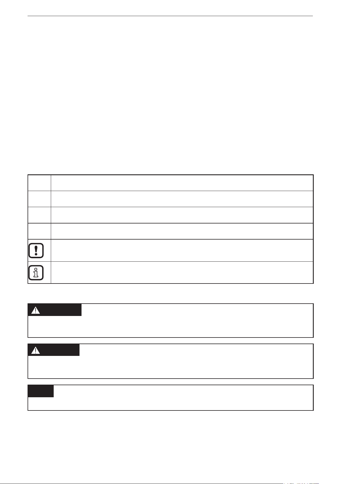
Symbols
►
Instructions
> Reaction, result
[…] Designation of keys, buttons or indications
→ Cross-reference
Important note
Non-compliance can result in malfunction or interference�
Information
Supplementary note
Warning signs used
WARNING
Warning of serious personal injury�
Death or serious irreversible injuries may result�
CAUTION
Warning of personal injury�
Slight reversible injuries may result�
NOTE
Warning of damage to property�
4

Field modules DP
2 Safety instructions
These instructions contain texts and figures concerning the correct handling of the
device and must be read before installation or use�
Observe the operating instructions� Non-observance of the instructions, operation
which is not in accordance with use as prescribed below, wrong installation or
incorrect handling can seriously affect the safety of operators and machinery�
► Prepare installation
► Disconnect the power supply of the device�
► Ensure that devices cannot be accidentally restarted�
► Verify safe isolation from the supply�
► Earth and short circuit�
► Cover or enclose adjacent units that are live�
UK
► Follow the specific mounting instructions of the device�
► Only suitably qualified personnel in accordance with EN 50 110-1/-2 (VDC
0105 part 100) is permitted to work on this device/system�
► Before installation and before touching the device ensure that you are free of
electrostatic charge�
► The funtional earth (FE) must be connected to the protective earth (PE) or to
the potential equalisation� The system installer is responsible for implementing
this connection�
► Connecting cables and signal lines must be installed in such a manner that
inductive or capacitive interference do not impair the automatic functions�
► Install automation equipment and related operating elements in such a way that
they are protected against unintentional operation�
► Suitable safety hardware and software measures should be implemented for
the I/O interface so that a line or wire breakage on the signal side does not
result in undefined states in the automation device�
► Ensure a reliable electrical isolation of the low voltage for the 24 V supply�
Only use power supplies compliant with IEC 60 364-4-41 or HD 384�4�41 S2
(VDE 0100 part 410) �
► Fluctuations or deviations of the mains voltage from the rated value must not
exceed the tolerance limits specified in the technical data, otherwise this may
cause malfunction and dangerous operation�
► E-stop devices to IEC/EN 60 204-1 must be effective in all operating modes of
the automation device� Unlatching the e-stop devices must not cause restart�
5

Field modules DP
► Devices that are designed for mounting in housings or control cabinets must
only be operated and controlled after they have been installed with the housing
closed� Desktop or portable units must only be operated and controlled in
enclosed housings�
► Measures should be taken to ensure the proper restart of programs interrupted
after a voltage dip or failure� This should not cause dangerous operating states
even for a short time� If necessary, an emergency stop must be carried out�
► Wherever faults in the automation system may cause personal injuries or
damage to property, external measures must be implemented to ensure a safe
operating state in the event of a fault or malfunction (e�g� by means of separate
limit switches, mechanical interlocks etc�)
► The electrical installation must be carried out in accordance with the relevant
regulations (e�g� with regard to cable cross-sections, fuses, PE)�
► All work relating to transport, installation, commissioning and maintenance
must only be carried out by qualified personnel� (IEC 60 364 or HD 384 or
DIN VDE 0100 and national work safety regulations have to be observed)�
► All shrouds and doors must be kept closed during operation�
3 Documentation
This documentation relates to the hardware and firmware status at the time of
editing this manual� The features of the devices are continuously developed further
and improved�
3.1 Firmware and hardware status
3.1.1 Downward compatibility
The modules are downward compatible� Older modules cannot, however,
feature the same characteristics as new module versions� However, existing
characteristics have been retained so that older modules can always be replaced
with the new ones�
The documentation describes the differences between the modules�
The firmware and hardware status of the modules can be taken from the version
number printed on the side of the module� The version number can be identified by
the prefix "D"�
6
Firmware and hardware status
21
12
Indication on module Declaration Example
D� kkjjxyzu D�22011501
kk Calendar week Week 22
jj Year of the year 2001
Field modules DP
x Firmware bus board Firmware bus, version 1
y Hardware bus board Hardware, version 5
z Firmware I/O board Firmware I/O, 0 (no firmware needed for
this board)
u Hardware I/O board Hardware I/O, version 1
4 Connections
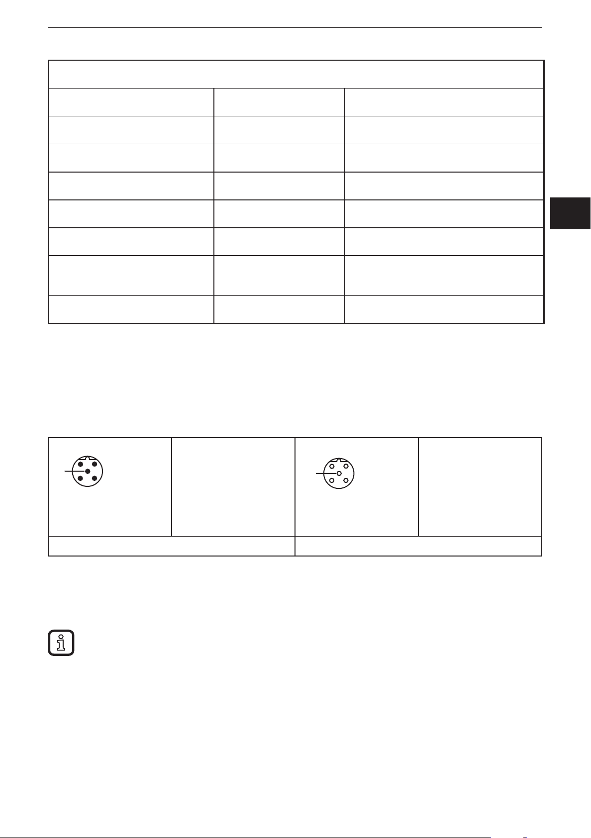
4.1 Fieldbus connection
The fieldbus connection is established using reverse-keyed M12x1 connectors�
1: not connected
5
3
4
2: line A
3: GND
4: line B
5: shield (also on
coupling nut)
5
4
3
1: 5 V DC
2: line A
3: GND
4: line B
5: shield (also on
coupling nut)
UK
M12 connector for the in-coming bus line M12 connector for the outgoing bus line
4.2 Fieldbus termination
The bus is terminated using an external terminating resistor� The modules are not
capable of fieldbus termination�
4.3 Nominal current consumption of modules connected to PROFIBUSDP
It is important to consider the current consumption of the individual modules for
power-feed, module protection and assessment of the voltage drop on the power
cable�
Chapter 7 contains a table with the nominal current consumption of the modules�
The bus termination must be accomplished externally using a connector with integrated terminating
resistor (E12315) as passive terminating resistor�
7
Field modules DP
4.4 Connection to a Siemens PLC type S7-300
In order to describe the connection of the modules to an S7-300 type Siemens
controller, the software package "SIMATIC Manager" version 5�5 with Service
Pack 2 from the company Siemens is used�
4.4.1 Importing the GSD le
Prior to initial configuration of the system in the hardware configurator of the
software, the GSD files must be imported into the software�
Start the software and proceed as follows to import the above GSx files:
► Open new or existing project�
► Open hardware configurator
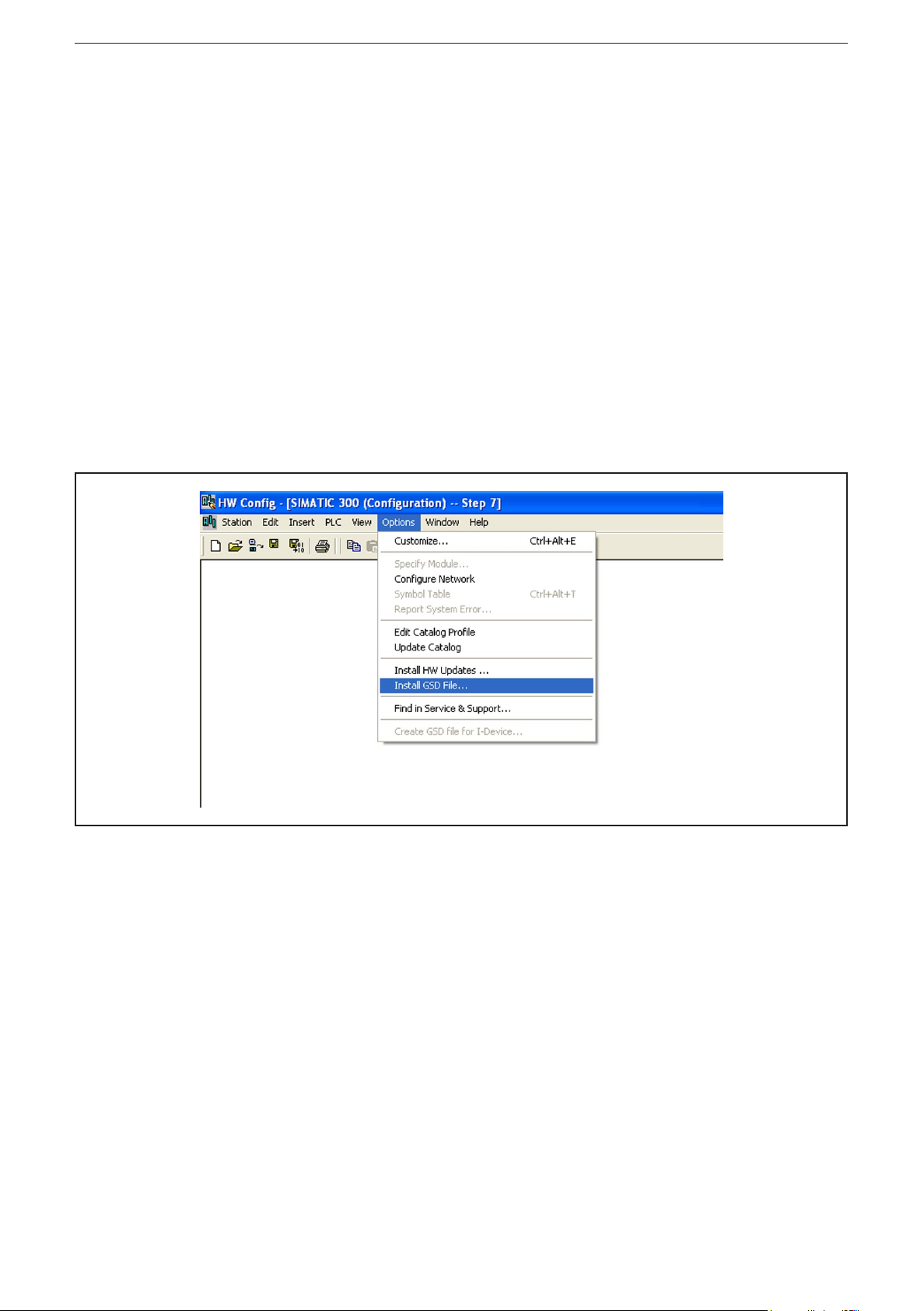
Copy the required GSx file to the software via menu item [Options] → [Install GSD
File���]�
Importing a GSD file
8
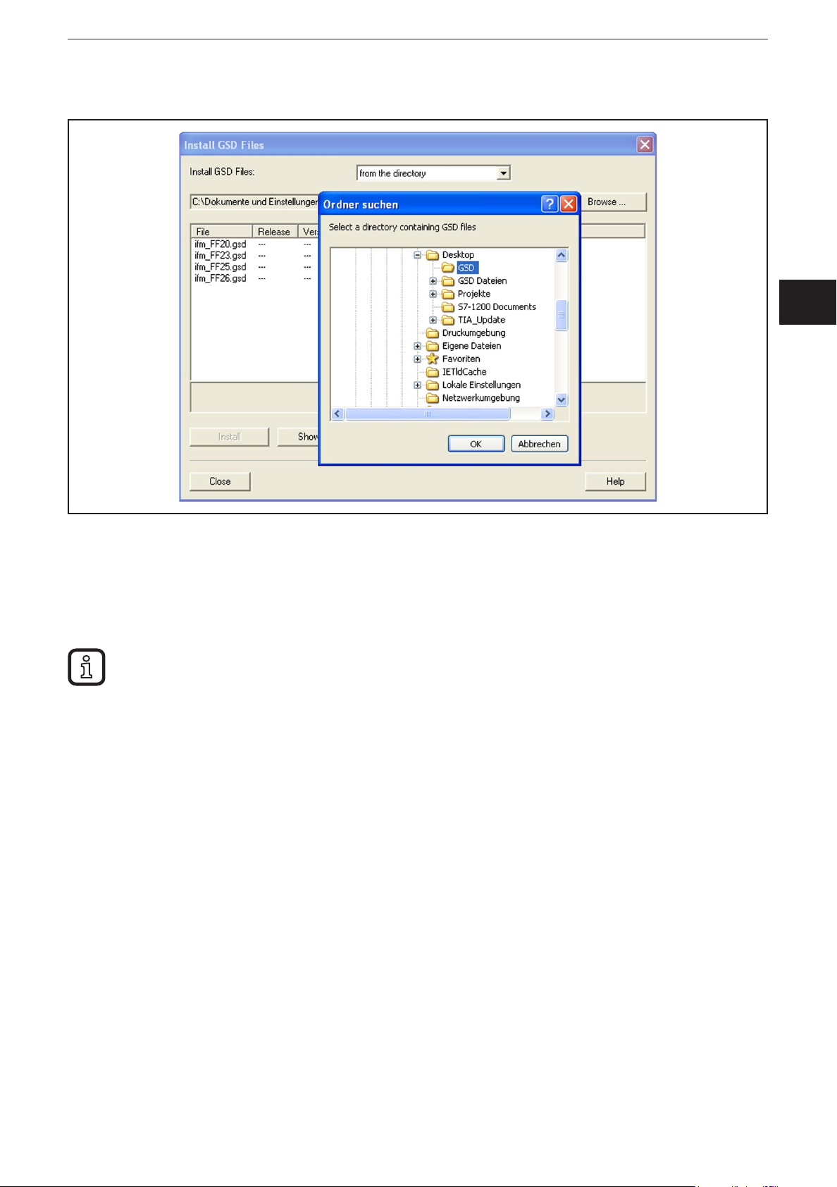
► Select the GSD file from the according source directory�
Field modules DP
UK
Selecting the GSD file from the directory
After correct import and an update of the hardware catalogue via [Options]
→ [Update Catalog] the modules will be displayed as separate entries in the
hardware catalogue�
The exact configuration procedure can be found in the operating manual which is supplied together
with the software�
9
Field modules DP
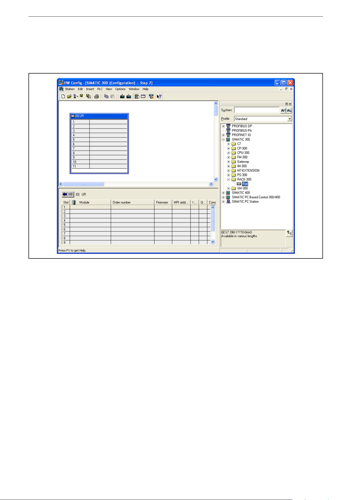
Selecting a CPU
First, select a module rack� In this example, rack 300 is selected under
[SIMATIC 300] → [RACK 300]
Selecting the module rack
Then the CPU type is determined�
10
Field modules DP
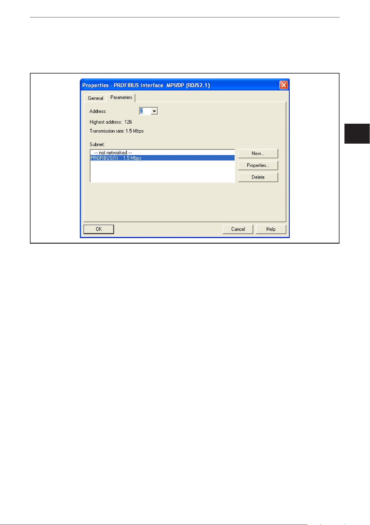
Enter the PROFIBUS address of the CPU in the dialogue box and select the
subnet [PROFIBUS]�
Use the button [Properties] to further define the subnet�
UK
Selecting the subnet
11
 Loading...