

Page 1

Programming Manual
AS-i Gateway AC14
with fieldbus interfaces
AC1401/02
AC1411/12
AC1421/22
Firmware release: 4.2.x
CODESYS release: 3.5.9.73 or higher
English
7391196/00 12/2017
Page 2

ifm Programming Manual AS-i Gateway AC14 (4.2.x) 12/2017
Content
Contents
1 Preliminary note 4
1.1 Legal and copyright information ........................................................................................... 4
1.2 Purpose of the document ..................................................................................................... 4
1.3 Symbols and styles used ..................................................................................................... 5
1.4 Overview: User documentation for AS-i Gateway AC14 ..................................................... 5
1.5 Overview: CODESYS documentation of 3S ........................................................................ 6
1.6 Modification history .............................................................................................................. 6
2 Safety instructions 7
2.1 General safety instructions .................................................................................................. 7
2.2 Required background knowledge ........................................................................................ 7
2.3 Warnings used ..................................................................................................................... 8
3 System requirements 9
3.1 Hardware .............................................................................................................................. 9
3.2 Software ............................................................................................................................... 9
3.3 Licensing ............................................................................................................................10
4 Installation 11
4.1 CODESYS programming software .....................................................................................11
4.1.1 Install CODESYS Development System..................................................................................... 11
4.2 ifm AS-i Package................................................................................................................12
4.2.1 Components of the ifm package ................................................................................................. 12
4.2.2 Install the ifm package ................................................................................................................ 13
4.2.3 Update ifm package ................................................................................................................... 13
4.2.4 Uninstall the ifm package ........................................................................................................... 14
5 Getting started 15
5.1 Create CODESYS project ..................................................................................................16
5.1.1 Create new project with AS-i Gateway AC14 ............................................................................. 17
5.1.2 Overview: Project structure with AS-i Gateway AC14 ................................................................ 18
5.2 Use CODESYS online help ................................................................................................19
5.3 Set the programming interface ...........................................................................................20
5.3.1 Set communication path to PLC ................................................................................................. 20
6 System configuration 21
6.1 Configure PLC....................................................................................................................21
6.2 Configure Ethernet interface ..............................................................................................22
6.2.1 Available fieldbus stacks ............................................................................................................ 22
6.2.2 Add fieldbus stack ...................................................................................................................... 23
7 Programming 24
7.1 Objects of a PLC application ..............................................................................................24
7.2 Create PLC application ......................................................................................................25
7.2.1 Use remanent variables.............................................................................................................. 25
7.2.2 Supported programming languages ........................................................................................... 26
7.2.3 Change system time of the device ............................................................................................. 26
2
Page 3

ifm Programming Manual AS-i Gateway AC14 (4.2.x) 12/2017
Content
7.3 Access input and output data .............................................................................................27
7.3.1 Options to access input and output data .................................................................................... 27
7.3.2 Validity of the interface data ....................................................................................................... 28
7.3.3 Process data of the AS-i slaves .................................................................................................. 29
7.3.4 Fieldbus data .............................................................................................................................. 31
7.4 Use functions of the ifm package .......................................................................................33
7.4.1 Control interface of the ifm function blocks ................................................................................. 33
7.4.2 Configure system ....................................................................................................................... 35
7.4.3 Configure AS-i master ................................................................................................................ 35
7.4.4 Configure AS-i slaves ................................................................................................................. 35
7.4.5 Manage AS-i network ................................................................................................................. 36
7.4.6 Send commands to the system and the AS-i master .................................................................. 39
7.5 Use visualisations ..............................................................................................................40
7.5.1 Supported visualisation types ..................................................................................................... 40
7.5.2 Add visualisation to a project ...................................................................................................... 41
7.5.3 Create a visualisation ................................................................................................................. 42
7.5.4 Configure visualisation ............................................................................................................... 43
7.6 Configure task processing .................................................................................................45
7.6.1 Configure main task ................................................................................................................... 45
7.6.2 Set parameters for visualisation task .......................................................................................... 45
7.7 Testing the PLC application ...............................................................................................46
8 Operation 47
8.1 Transfer CODESYS project to device ................................................................................48
8.1.1 Activate CODESYS PLC ............................................................................................................ 49
8.1.2 Download the application to the device ...................................................................................... 50
8.1.3 Delete application from AS-i Gateway AC14 .............................................................................. 50
8.1.4 Delete boot application via SD card ........................................................................................... 51
8.2 Operating states of the PLC ...............................................................................................52
8.2.1 Operating mode of the PLC ........................................................................................................ 52
8.2.2 States of the PLC application ..................................................................................................... 52
8.2.3 Switch operating states .............................................................................................................. 53
8.3 Reset ..................................................................................................................................54
8.3.1 Supported reset variants ............................................................................................................ 54
8.3.2 Reset the application (warm) ...................................................................................................... 55
8.3.3 Reset the application (cold) ........................................................................................................ 55
8.3.4 Reset the application (origin) ...................................................................................................... 55
8.4 Display web visualisation ...................................................................................................56
8.5 Display target visualisation ................................................................................................57
9 Appendix 58
9.1 Library ACnnnn_Utils.library ..............................................................................................59
9.1.1 Overview: AS-i functions (FB_ASi) ............................................................................................. 60
9.1.2 Overview: System functions (FB_System) ............................................................................... 106
9.1.3 Enumeration types and complex variables ............................................................................... 113
9.2 Library ACnnnn_SYS_CMD.library ..................................................................................121
9.2.1 ACnnnn_SysCmd ..................................................................................................................... 121
10 Index 129
11 ifm weltweit • ifm worldwide • ifm à l’échelle internationale 131
3
Page 4

ifm Programming Manual AS-i Gateway AC14 (4.2.x) 12/2017
Preliminary note Legal and copyright information
1 Preliminary note
Legal and copyright information ............................................................................................................... 4
Purpose of the document ......................................................................................................................... 4
Symbols and styles used .......................................................................................................................... 5
Overview: User documentation for AS-i Gateway AC14 .......................................................................... 5
Overview: CODESYS documentation of 3S ............................................................................................. 6
Modification history ................................................................................................................................... 6
>
14801
1.1 Legal and copyright information
1631
© All rights reserved by ifm electronic gmbh. No part of this manual may be reproduced and used
without the consent of ifm electronic gmbh.
All product names, pictures, companies or other brands used on our pages are the property of the
respective rights owners:
AS-i is the property of the AS-International Association, (→ www.as-interface.net)
CAN is the property of the CiA (CAN in Automation e.V.), Germany (→ www.can-cia.org)
CODESYS™ is the property of the 3S – Smart Software Solutions GmbH, Germany
(→ www.codesys.com)
DeviceNet™ is the property of the ODVA™ (Open DeviceNet Vendor Association), USA
(→ www.odva.org)
EtherNet/IP® is the property of the →ODVA™
EtherCAT® is a registered trade mark and patented technology, licensed by Beckhoff Automation
GmbH, Germany
IO-Link® (→ www.io-link.com) is the property of the →PROFIBUS Nutzerorganisation e.V.,
Germany
ISOBUS is the property of the AEF – Agricultural Industry Electronics Foundation e.V.,
Deutschland (→ www.aef-online.org)
Microsoft® is the property of the Microsoft Corporation, USA (→ www.microsoft.com)
PROFIBUS® is the property of the PROFIBUS Nutzerorganisation e.V., Germany
(→ www.profibus.com)
PROFINET® is the property of the →PROFIBUS Nutzerorganisation e.V., Germany
Windows® is the property of the →Microsoft Corporation, USA
>
1.2 Purpose of the document
This document applies to the following devices of the type"AS-i Gateway AC14":
AS-i Gateway AC14 with Profinet device interface (AC1401/AC1402)
AS-i Gateway AC14 with Profibus slave interface (AC1411/AC1412)
SmartSPS AC14 with EtherNet/IP device interface (AC1421/AC1422)
It is part of the device and contains information about the correct handling of the product.
► Read this document before using the device.
► Keep this document during the service life of the device.
>
4
18872
Page 5

ifm Programming Manual AS-i Gateway AC14 (4.2.x) 12/2017
Preliminary note Symbols and styles used
1.3 Symbols and styles used
► ...
Instructions
> ...
Reaction, result
→ ...
Cross-reference or internet link
123
0x123
0b010
Decimal number
Hexadecimal number
Binary number
[...]
Designation of pushbuttons, buttons or indications
Document
Content / Description
Data sheet
Technical data of the device as a table
Operating instructions *
Notes on mounting and electrical installation of the device
Set-up, description of the operating and display elements, maintenance information, scale
drawing
Device manual
Notes on operation of the device via GUI and web interface
Error elimination
Description of the fieldbus data
Supplement device manual
Description of the acyclic data sets and the command interface
Programming manual
Creation of a project with the device using CODESYS
Configuration of the device using CODESYS
Programming of the PLC of the device
Description of the device-specific CODESYS function libraries
The user can download all documents from the ifm website.
>
1.4 Overview: User documentation for AS-i Gateway AC14
ifm electronic provides the following user documentation for the models of the device class "AS-i
Gateway AC14":
13839
6998
*... The operating instructions are supplied with the device.
5
Page 6
ifm Programming Manual AS-i Gateway AC14 (4.2.x) 12/2017
Preliminary note Overview: CODESYS documentation of 3S
>
Document
Content / Description
Online help
Context-sensitive help
Description of the CODESYS programming system
Description of components and function libraries
CODESYS installation and
first steps
Remarks about the installing of the CODESYS programming system
First steps for handling the CODESYS programming system
Version
Topic
Date
00
New creation of document
xx/201x
1.5 Overview: CODESYS documentation of 3S
18296
3S GmbH provides the following user documentation for programming PLC of AC4S:
After the installation of the CODESYS 3.5 programming system all documents are stored on the hard
disk of the PC/laptop and can be accessed:
Online help:
...\Program Files\3S CoDeSys\CoDeSys\Online-Help
CODESYS installation and first steps:
...\Program Files\3S CoDeSys\CoDeSys\Documentation
>
1.6 Modification history
21676
6
Page 7

ifm Programming Manual AS-i Gateway AC14 (4.2.x) 12/2017
Safety instructions General safety instructions
2 Safety instructions
General safety instructions ....................................................................................................................... 7
Required background knowledge ............................................................................................................. 7
Warnings used .......................................................................................................................................... 8
>
2.1 General safety instructions
8516
Read this document before setting up the product and keep it during the entire service life.
Only use the product for its intended purpose.
If the operating instructions or the technical data are not adhered to, personal injury and/or damage to
property may occur.
Improper or non-intended use may lead to malfunctions of the device, to unwanted effects in the
application or to a loss of the warranty claims.
The manufacturer assumes no liability for any consequences caused by tampering with the device or
incorrect use by the operator.
► Observe these operating instructions.
► Adhere to the warning notes on the product.
>
2.2 Required background knowledge
13323
This document is intended for people with knowledge of control technology and PLC programming to
IEC 61131-3.
To program the PLC, these people should also be familiar with the CODESYS software.
This document is intended for specialists. Specialists are people who, based on their relevant training
and experience, are capable of identifying risks and avoiding potential hazards that may be caused
during operation or maintenance of the product. The document contains information about the correct
handling of the product.
► Read this document before use to familiarise yourself with operating conditions, installation and
operation. Keep this document during the entire duration of use of the device.
► Follow the safety instructions.
213
7
Page 8
ifm Programming Manual AS-i Gateway AC14 (4.2.x) 12/2017
Safety instructions Warnings used
>
WARNING
Death or serious irreversible injuries may result.
CAUTION
Slight reversible injuries may result.
NOTICE
Property damage is to be expected or may result.
Important note
Non-compliance may result in malfunction or interference.
Information
Supplementary note.
2.3 Warnings used
13685
8
Page 9
ifm Programming Manual AS-i Gateway AC14 (4.2.x) 12/2017
System requirements Hardware
3 System requirements
Hardware .................................................................................................................................................. 9
Software.................................................................................................................................................... 9
Licensing.................................................................................................................................................10
Component
Description
Release
CODESYS Development System
Programming software CODESYS Development System
für PLC programming according to norm IEC 61131-3
3.5 SP9 Patch 7 Hotfix 3
Package "CODESYS for ifm SmartPLC
StandardLine"
Device and interface description of AS-i Gateway
AC14
Function libraries for programming of the PLC
1.6.4.14
The assured characteristics and functions described in this manuals are only accessible with
the indicated releases of the software components!
ifm electronic provides the software components for downloading on its website:
→ www.ifm.com > Service > Download > Industrial communication
>
16903
3.1 Hardware
16904
Device of the AS-i Gateway AC14 product family with firmware V4.2.x
PC/laptop for CODESYS development system (→ system requirements CODESYS development
system V3.x)
Ethernet connection between CODESYS-PC/laptop and configuration interface (X3) of the device
>
3.2 Software
16905
To program the device-internal PLC of the AS-i Gateway AC14, the following software components
are required:
9
Page 10

ifm Programming Manual AS-i Gateway AC14 (4.2.x) 12/2017
System requirements Licensing
>
Article description
Article no.
1x CODESYS V3 license AS-i Gateway AC14
E71400
Use of the device-internal CODESYS PLC of AS-i Gateway AC14 without valid license
constitutes a violation of applicable law!
3.3 Licensing
All models of the device family AS-i Gateway AC14, to be programmed using the CODESYS
Development System 3.5 SP9 Patch 7 Hotfix 3, must be licensed. A valid license label can be
purchased from ifm electronic.
16906
10
Page 11

ifm Programming Manual AS-i Gateway AC14 (4.2.x) 12/2017
Installation CODESYS programming software
4 Installation
CODESYS programming software .........................................................................................................11
ifm AS-i Package ....................................................................................................................................12
>
4.1 CODESYS programming software
The CODESYS Development System (short: CODESYS) is a platform for the creation of PLC
applications according to the standard IEC 61131-3.
>
4.1.1 Install CODESYS Development System
To install the software "CODESYS Development System":
► Install the programming system CODESYS 3.5 SP9 Patch 7 Hotfix 3 (→ CODESYS installation and first steps).
> CODESYS 3.5 SP9 Patch 7 Hotfix 3 is installed on the programming PC/laptop.
17146
7282
18596
11
Page 12

ifm Programming Manual AS-i Gateway AC14 (4.2.x) 12/2017
Installation ifm AS-i Package
>
Components of the ifm package .............................................................................................................12
Install the ifm package ............................................................................................................................13
Update ifm package ................................................................................................................................13
Uninstall the ifm package .......................................................................................................................14
► Familiarise yourself with the following CODESYS functions!
Package Manager
→ Online help > CODESYS Development System > Manage packages and licences
Component
Description
AC14SL.devdesc.xml
Device description of the basic module
ACnnnn_EthernetAdapterSL.devdesc.xml
Device description of Ethernet interface
ACnnnn_Modbus_Master.devdesc.xml
Device description of the Modbus master (extension of the Ethernet interface)
ACnnnn_Modbus_Slave.devdesc.xml
Device description of the Modbus slave device (extension of the Ethernet
interface)
ACnnnn_Utils.library
Function library with AS-i Gateway AC14 specific CODESYS function blocks and
data structures
ACnnnn_SYS_CMD.library
Function library with function block for access to the command interface of AS-i
Gateway AC14 from a CODESYS application
AC14SL.template
Template for AC14 StandardLine
AC14SL.template.project
Template for AC14 StandardLine project
AC14.ico
Symbol image of the AC14
4.2 ifm AS-i Package
>
4.2.1 Components of the ifm package
To program the AS-i Gateway AC14, ifm provides the CODESYS package "CODESYS for ifm
SmartPLC StandardLine" (short: ifm package). The ifm package (file:
ifm_SmartPLC_StandardLine_V1_6_4_14.package) contains the following components:
17679
17552
12
Page 13

ifm Programming Manual AS-i Gateway AC14 (4.2.x) 12/2017
Installation ifm AS-i Package
>
4.2.2 Install the ifm package
To install the package "CODESYS for ifm SmartPLC StandardLine":
Requirements:
> CODESYS 3.5 SP9 Patch 7 Hotfix 3 is installed on the programming PC/notebook.
1 Start CODESYS
► Start CODESYS with administrator rights.
> CODESYS programming interface appears.
2 Install the ifm package in CODESYS
► Select [Tools] > [Package Manager].
> Window [Package Manager] is displayed.
► Click on [Install...] to start the installation dialogue.
► Select the downloaded ifm package and carry out a complete installation.
> The [Package Manager] window displays the installed ifm package.
► Press [Exit] to close the package manager.
>
4.2.3 Update ifm package
To update an installed package "CODESYS for ifm SmartPLC StandardLine":
1 Download new version of the ifm package
► Got to the product page of the device on the ifm website.
► Download ifm_SmartPLC_StandardLine_V1_6_4_14.package and save it on the CODESYS PC/laptop.
2 Uninstall the old version of the ifm package
► → Uninstall the ifm package (→ p. 14)
3 Install a new version of the ifm package
► → Install the ifm package (→ p. 13)
4 Update device libraries
► In the device tree: Click on [Device (ifm_SmartPLC_StandardLine)].
► Select [Project] > [Update Device].
> [Update Device] windows appears.
► Click on [Update Device] to start the update process.
> New device libraries are loaded.
> Project tree view is updated.
► Click on [Exit] to close the Package Manager.
► Save the project.
7283
12267
13
Page 14

ifm Programming Manual AS-i Gateway AC14 (4.2.x) 12/2017
Installation ifm AS-i Package
>
4.2.4 Uninstall the ifm package
To uninstall the package "CODESYS for ifm SmartPLC StandardLine":
1 Start CODESYS
► Start CODESYS with administrator rights.
> CODESYS programming interface appears.
2 Uninstall the ifm package
► Select [Tools] > [Package Manager] to access the package manager.
> Window [Package Manager] shows the installed packages.
► Activate [Display version] checkbox.
> The window shows the version numbers of the installed packages.
► Select the package version to be uninstalled
► Click on [Uninstall...] to uninstall the selected package.
> The selected package version is uninstalled.
► Click on [Exit] to close the Package Manager.
12270
14
Page 15

ifm Programming Manual AS-i Gateway AC14 (4.2.x) 12/2017
Getting started ifm AS-i Package
5 Getting started
Create CODESYS project ......................................................................................................................16
Use CODESYS online help ....................................................................................................................19
Set the programming interface ...............................................................................................................20
15858
15
Page 16

ifm Programming Manual AS-i Gateway AC14 (4.2.x) 12/2017
Getting started Create CODESYS project
>
Create new project with AS-i Gateway AC14 .........................................................................................17
Overview: Project structure with AS-i Gateway AC14 ............................................................................18
► Familiarise yourself with the following CODESYS functions!
Create CODESYS project
→ Online help > CODESYS Development System > Create and configure project
Objects of the user interface
→ Online help > CODESYS Development System > Reference user interface
5.1 Create CODESYS project
17129
16
Page 17
ifm Programming Manual AS-i Gateway AC14 (4.2.x) 12/2017
Getting started Create CODESYS project
>
To avoid errors during manual system configuration, it is explicitly recommended to use the
project template from ifm electronic when creating the AS-i Gateway AC14 project in
CODESYS.
5.1.1 Create new project with AS-i Gateway AC14
Qualifications
> All required software components are correctly installed (→ Installation (→ p. 11)).
> CODESYS successfully started.
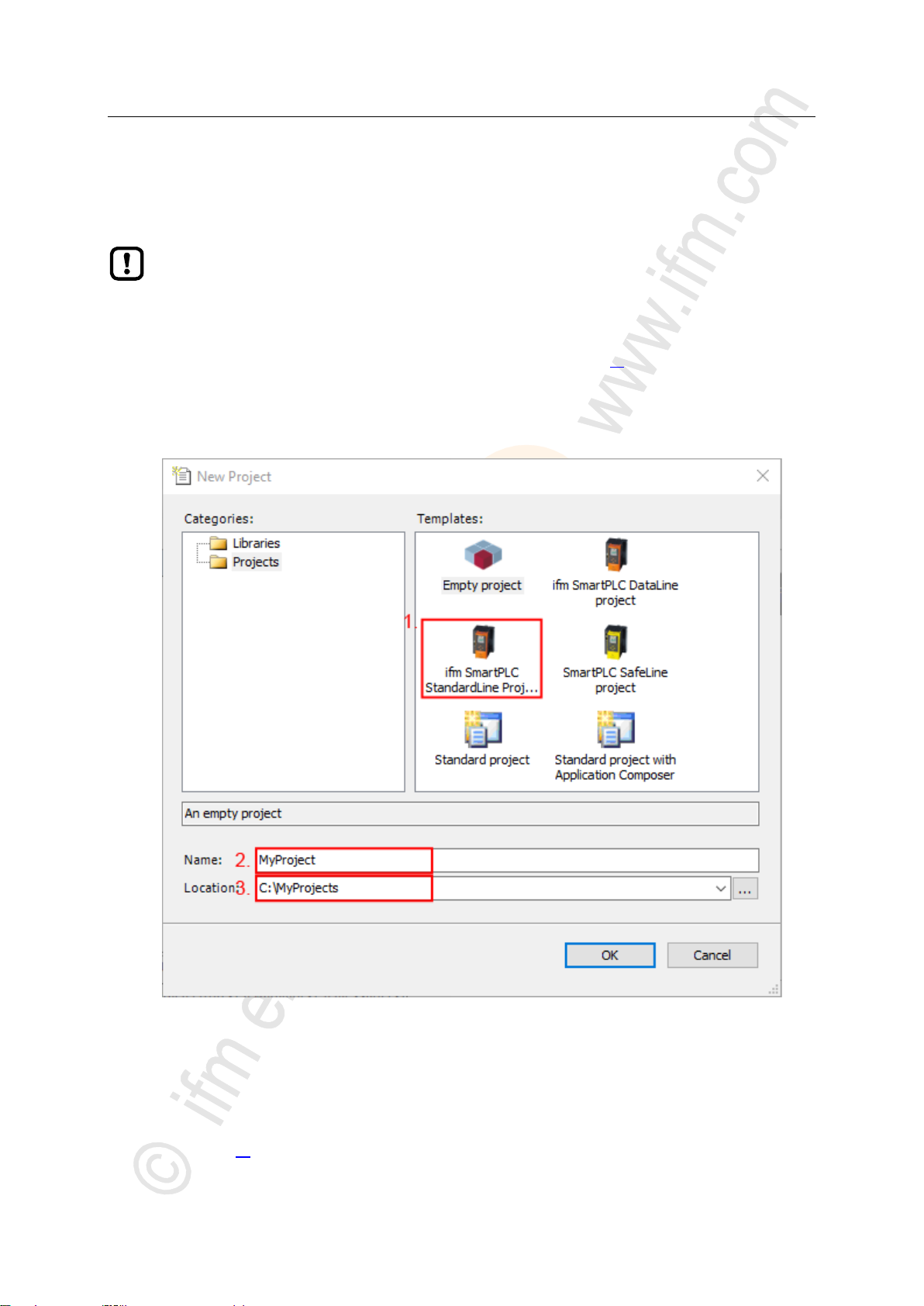
1 Create a new project
► Select [File] > [New Project...].
> The window to enter the project properties appears:
17682
► Set the following values:
1. [Templates]: Select [ifm_SmartPLC_StandardLine Projekt].
2. [Name]: Enter project name
3. [Location]: Select the storage location of the project file.
► Click on [OK] to verify the entered values.
> CODESYS creates a new project with AS-i Gateway AC14.
> The window [Devices] shows the device tree of the project (→ Overview: Project structure with AS-i Gateway
AC14 (→ p. 18)).
17
Page 18
ifm Programming Manual AS-i Gateway AC14 (4.2.x) 12/2017
Getting started Create CODESYS project
2 Save the project
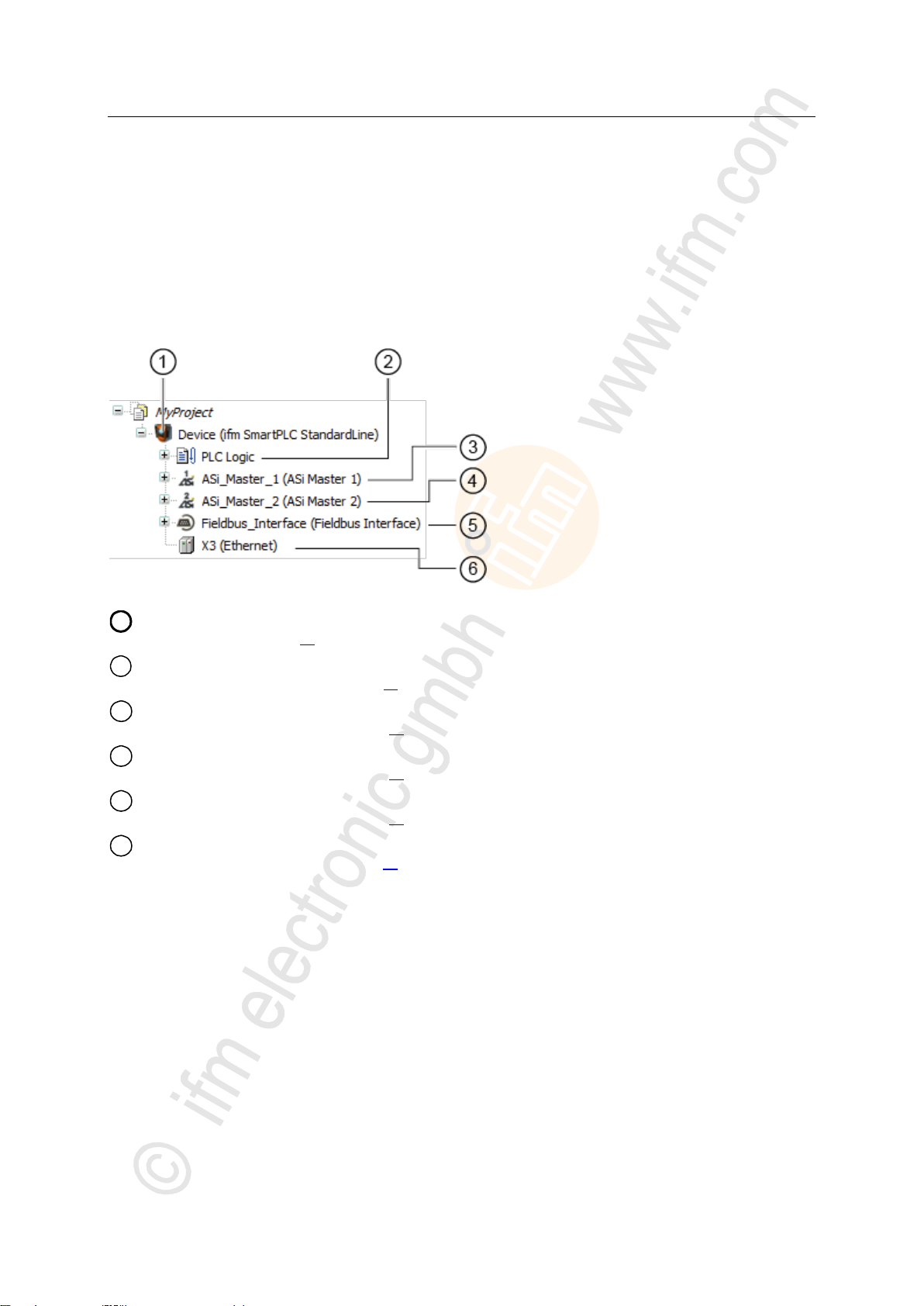
1
[Device (AC14)] represents the AS-i Gateway AC14 in the CODESYS project.
→ Configure PLC (→ p. 21)
2
[PLC Logic] contains the PLC applications of the AS-i Gateway AC14.
→ Objects of a PLC application (→ p. 24)
3
[ASi_Master_1] contains the process data images of the AS-i slaves at AS-i master 1
→ Access input and output data (→ p. 27)
4
[ASi_Master_2] contains the process data images of the slaves at AS-i master 2
→ Access input and output data (→ p. 27)
5
[Fieldbus_Interface] provides access to the inputs and outputs of the fieldbus interface.
→ Access input and output data (→ p. 27)
6
[Ethernet] represents the configuration node Ethernet adapter of the device.
→ Configure Ethernet interface (→ p. 22)
► Select [File] > [Save Project].
> CODESYS saves the project.
>
5.1.2 Overview: Project structure with AS-i Gateway AC14
17132
A CODESYS project contains all components for the programming and administration of PLC
applications. All components of a project are shown in the window [Devices] in a hierarchic tree view.
CODESYS projects with an AS-i Gateway AC14 have the following structure:
18
Page 19

ifm Programming Manual AS-i Gateway AC14 (4.2.x) 12/2017
Getting started Use CODESYS online help
>
► Familiarise yourself with the CODESYS development system! In particular with the
following topics:
Names and functions of the user interface elements
Basic menu functions
Programming techniques and methods for data retention
5.2 Use CODESYS online help
6989
This manual only describes the integration, configuration and the programming of the AS-i Gateway
AC14 using the CODESYS development system.
For the description of user actions and user interface elements the CODESYS terminology will be
used.
Standard functions and methods of CODESYS will not be described. At the beginning of each section
there will be a reference to the corresponding chapters of the CODESYS online help.
To access the online help of the CODESYS development system:
► Start CODESYS.
> The CODESYS user interface appears.
► Press [F1].
> Online help of the CODESYS development system appears.
19
Page 20
ifm Programming Manual AS-i Gateway AC14 (4.2.x) 12/2017
Getting started Set the programming interface
>
5.3 Set the programming interface
To download the created projects and applications to the device a valid network path between the
CODESYS programming system and the PLC of the device has to be selected.
>
5.3.1 Set communication path to PLC
To configure the connection between CODESYS programming software and the PLC of the AS-i
Gateway AC14:
1 Preparations
► Connect CODESYS PC/laptop and configuration interface (X3) of the device.
► Optional: Adjust IP settings of the Ethernet interfaces.
2 Select communication settings
► In the device tree: Double click on [Device ifm_SmartPLC_StandardLine]
► In the editor window: Click on [Communiation Settings] tab.
> Editor window shows the communication settings of the device.
3 Select gateway
► Select the required gateway from the [Gateway] list.
► List shows the selected gateway.
4 Select network path
► Press [Scan network...].
> [Select Device] window appears.
► Select gateway and press [Scan network] to start the scanning process.
> CODESYS scans the Ethernet network for accessible devcies.
> Window shows network path and detected devices.
18494
18500
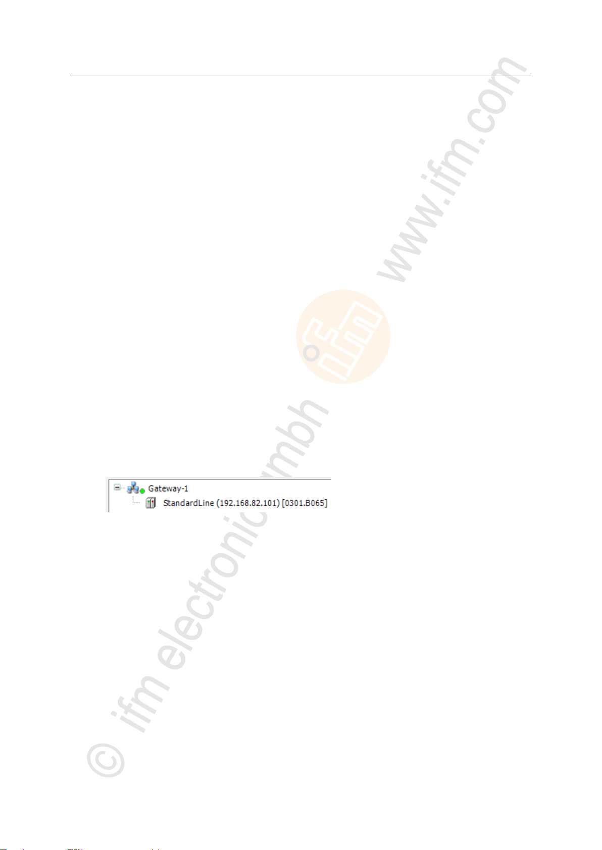
► Select the [AS-i Gateway AC14] node.
> Information field displays detailed information of the selected node.
► Press [OK] to select the network path to the PLC.
> CODESYS is able to download data to the PLC of the AS-i Gateway AC14.
20
Page 21

ifm Programming Manual AS-i Gateway AC14 (4.2.x) 12/2017
System configuration Configure PLC
6 System configuration
Configure PLC ........................................................................................................................................21
Configure Ethernet interface...................................................................................................................22
► Familiarise yourself with the following CODESYS functions!
Generic device editor
→ Online help > CODESYS Development System > Reference user interface >
Objects> object 'device' and generic device editor
>
6.1 Configure PLC
The PLC is configured via the "Generic Device Editor" of the CODESYS programming system. The
programmer can access the device editor of the PLC via the following node in the device tree:
To configure the device-internal PLC:
► In the device tree: Double-click on [ifm_SmartPLC_StandardLine]
> The editor window shows device editor of the device-internal PLC.
► Configure PLC.
► Save the project to apply changes.
18498
18961
21
Page 22
ifm Programming Manual AS-i Gateway AC14 (4.2.x) 12/2017
System configuration Configure Ethernet interface
>
Available fieldbus stacks ........................................................................................................................22
Add fieldbus stack ..................................................................................................................................23
► Familiarise yourself with the following CODESYS functions!
Menu command "Attach device"
→ Online help > CODESYS Development System > Devices > Attach Device...
Configure EtherCAT (master)
→ Online help > Fieldbus support > EtherCAT Configuration Editor
Configure modbus TCP (master/slave)
→ Online help > Fieldbus support > Modbus Configuration Editor
Designation
Fieldbus
Manufacturer
Modbus TCP Master
Modbus TCP
3S - Smart Software Solutions GmbH
Modbus TCP Slave
Modbus TCP
3S - Smart Software Solutions GmbH
6.2 Configure Ethernet interface
>
6.2.1 Available fieldbus stacks
The Ethernet internet (X3) of the device can be declared and operated as an additional fieldbus
interface. For this, a fieldbus stack must be assigned to the interface in CODESYS. Presently, the
device supports the following fieldbus stacks:
17701
18518
22
Page 23

ifm Programming Manual AS-i Gateway AC14 (4.2.x) 12/2017
System configuration Configure Ethernet interface
>
► Familiarise yourself with the following CODESYS functions!
Modbus configurator
→ Online help > Fieldbus support > Modbus configurator
6.2.2 Add fieldbus stack
To declare the Ethernet interface as a fieldbus interface:
1 Create/load CODESYS project
► Create or load CODESYS project with the AS-i Gateway AC14.
2 Add fieldbus stack
► In the device tree: Right-click on [X3 (Ethernet)].
► In the context menu: Select [Add Device...].
> Window [Add device] appears.
► Set the following values:
1. [Vendor]: Select [<All vendors>].
2. In table: Select the requested fieldbus stack in the [Name] column.
3. [Name]: Enter name of the fieldbus stack.
► Click on [Add Device]to add the requested fieldbus stack to the project.
> In the device tree: CODESYS adds the selected fieldbus stack as sub-element of the Ethernet interface.
3 Configure the fieldbus stack
► Configure added fieldbus device.
► Save the project to apply changes.
18659
23
Page 24
ifm Programming Manual AS-i Gateway AC14 (4.2.x) 12/2017
Programming Objects of a PLC application
7 Programming
Objects of a PLC application ..................................................................................................................24
Create PLC application ...........................................................................................................................25
Access input and output data .................................................................................................................27
Use functions of the ifm package ...........................................................................................................33
Use visualisations ...................................................................................................................................40
Configure task processing ......................................................................................................................45
Testing the PLC application....................................................................................................................46
► Familiarise yourself with the programming according to the standard IEC 61131-3!
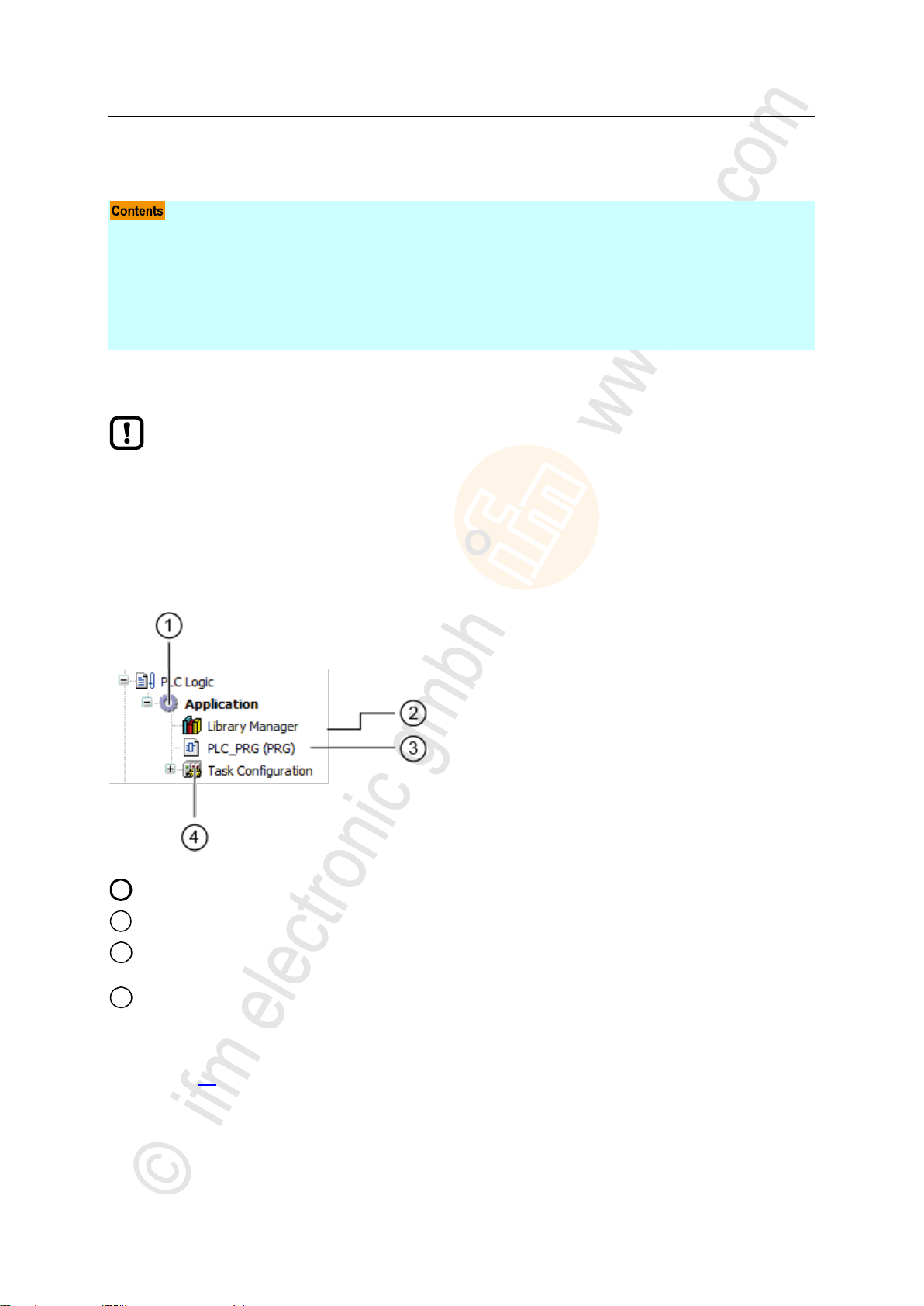
1
[Application] is the container of the PLC application
2
[Library manager] provides access to the standard and device-specific function libraries.
3
[PLC_PRG (PRG)] provides access to the program editor of the application
→ Create PLC application (→ p. 25)
4
[Task configuration] provides access to the settings of the task processing
→ Configure main task (→ p. 45)
This chapter provides information about the programming of the PLC of the device.
>
7.1 Objects of a PLC application
All objects of a PLC application are listed as subelements of the node [Application] in the device tree.
In the basic configuration a PLC application contains the following objects:
7074
7143
If needed, the programmer can add additional objects to the PLC application (→ Add visualisation to a
project (→ p. 41)).
24
Page 25
ifm Programming Manual AS-i Gateway AC14 (4.2.x) 12/2017
Programming Create PLC application
>
► Familiarise yourself with the following CODESYS functions!
Program application
→ Online help > CODESYS Development System > Program application
Programming reference
→ Online help > CODESYS Development System > reference programming
The memory area for RETAIN variables comprises 4072 bytes.
► Pay attention to the maximum size of the RETAIN memory area when declaring RETAIN
variables!
7.2 Create PLC application
To create a PLC application:
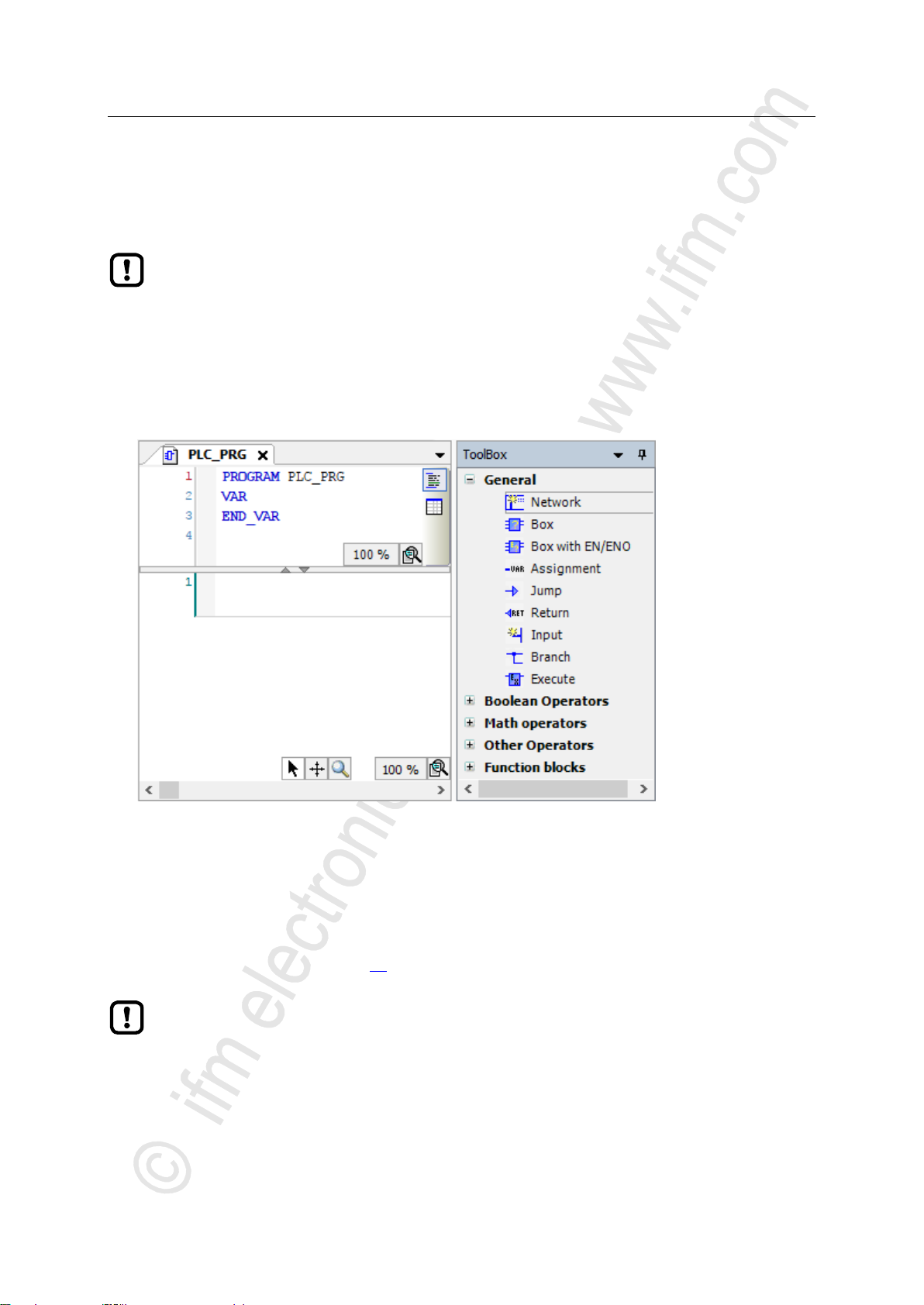
► In device tree: Double-click on [PLC_PRG (PRG)]
> The editor window shows the programming surface:
17691
► Program the application in the editor.
>
7.2.1 Use remanent variables
The PLC of the device supports the use of remanent variables. Variables declared as VAR RETAIN
are stored in a memory area that is also maintained when the device is switched off.
The declaration of a variable as RETAIN also influences its behaviour when the PLC application is
reset (→ Supported reset variants (→ p. 54)).
18522
25
Page 26

ifm Programming Manual AS-i Gateway AC14 (4.2.x) 12/2017
Programming Create PLC application
>
Library
ion Block Diagram (FBD)
ACnnnn_Utils.library
X X X X X
X
ACnnnn_SYS_CMD.library
X X X X X
X
Legend:
X ... is supported
WARNING
Risk of undesired system behaviour!
The use of the CODESYS function SysTimeRtcSet for setting the time may lead to malfunction.
► To set the system time (date, time) of the device only use the following device-specific commands:
Function block Set_DateTime (→ Set_TimeDate (→ p. 111))
System command 0x1109 with function block ACnnnn_SysCmd (→ ACnnnn_SysCmd
(→ p. 121))
7.2.2 Supported programming languages
The following table shows which programming languages according to IEC 61131 are supported by
the ifm function libraries:
18034
>
7.2.3 Change system time of the device
18271
26
Page 27

ifm Programming Manual AS-i Gateway AC14 (4.2.x) 12/2017
Programming Access input and output data
>
Options to access input and output data ................................................................................................27
Validity of the interface data ...................................................................................................................28
Process data of the AS-i slaves .............................................................................................................29
Fieldbus data ..........................................................................................................................................31
► Familiarise yourself with the following CODESYS functions!
Addresses according to IEC standard 61131-3:
→ Online help > CODESYS Development System > Programming Reference >
Operanden > Addresses
Access to IEC address via AT declaration:
→ Online help > CODESYS Development System > Programming Reference >
Declaration > AT Declaration
Definition of an ALIAS for an IEC address:
→ Online help > CODESYS Development System > Programming Reference > Data
Types > References
Coupling of a program variable to an address (mapping):
→ Online help > CODESYS Development System > Configuring I/O Links
7.3 Access input and output data
>
17447
7.3.1 Options to access input and output data
In a CODESYS project, each input and output has a physical address according to the IEC standard
(e.g. %IW5). CODESYS offers the following options to access this address from a PLC application and
thereby to access the input and outputs data of the device:
Direct access to IEC address
Access to IEC address via AT declaration
Definition of an ALIAS for an IEC address
Link a program variable to an IEC address (mapping)
17621
27
Page 28
ifm Programming Manual AS-i Gateway AC14 (4.2.x) 12/2017
Programming Access input and output data
>
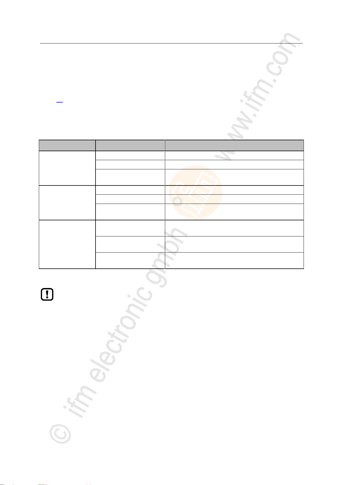
Output control
I/O interfaces
Updated address areas / channels
Manual
[ASi_Master_1]
AS-i 1 Input (%IB, %IW)
[ASi_Master_2]*
AS-i 2 Input (%IB, %IW)
[Fieldbus_Interface]
AS-i 1 Output (%IB, %IW)
AS-i 2 Output (%IB, %IW)
Gateway
[ASi_Master_1]
ASi 1 Input (%IB, %IW)
[ASi_Master_2]*
AS-i 2 Input (%IB, %IW)
[Fieldbus_Interface]
AS-i 1 Output (%IB, %IW)
AS-i 2 Output (%IB, %IW)
PLC
[ASi_Master_1]
AS-i 1 Input (%IB, %IW)
AS-i 1 Output (%QB, %QW)
[ASi_Master_2]*
AS-i 2 Input (%IB, %IW)
AS-i 2 Output (%QB, %QW)
[Fieldbus_Interface]
AS-i 1 Output (%IB, %IW)
AS-i 2 Output (%IB, %IW)
* ... only available for devices with 2 AS-i masters
► When linking variables with inputs and outputs, only use interfaces in the project tree, that
are updated by the CODESYS data mapper!
7.3.2 Validity of the interface data
18413
In order to facilitate the access to inputs and outputs of AS-i slaves, AS-i Gateway AC14 projects offer
clearly defined interfaces in the device tree (→ Overview: Project structure with AS-i Gateway AC14
(→ p. 18)).
Depending on the active instance for accessing the outputs of the AS-i slaves (Manual, Gateway,
PLC), the CODESYS data mapper only updates certain address areas of the interfaces. The following
table shows which address areas of the i/o interfaces provide valid data values while in a certain
operating mode:
28
Page 29
ifm Programming Manual AS-i Gateway AC14 (4.2.x) 12/2017
Programming Access input and output data
>
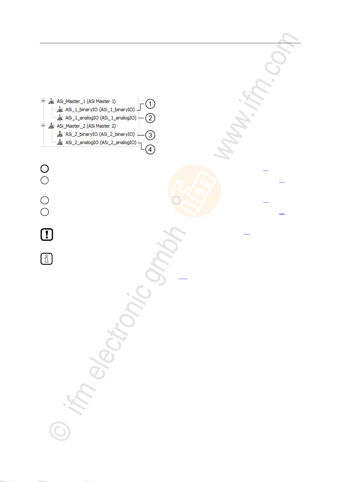
1
Digital input and output data of the slave at AS-i master 1: → Digital input and output data (→ p. 30)
2
Analogue input and output data of the slaves at AS-i master 1: → Analogue input and output data (→ p. 30)
3
Digital input and output data of the slave at AS-i master 2: → Digital input and output data (→ p. 30)
4
Analogue input and output data of the slaves at AS-i master 2: → Analogue input and output data (→ p. 30)
Consider validity of the interface data (→ Validity of the interface data (→ p. 28))!
The function library ACnnnn_Utils.library contains the complex variable ASi_NET. The
variable represents all inputs and outputs of a completely developed AS-i network. The
programmer can use this data structure to store the process images of the inputs and outputs
of an AS-i network. (→ ASI_NET (STRUCT) (→ p. 117))
7.3.3 Process data of the AS-i slaves
17584
The project tree offers direct access to the cyclically updated process images of the inputs and outputs
of the AS-i slaves.
29
Page 30
ifm Programming Manual AS-i Gateway AC14 (4.2.x) 12/2017
Programming Access input and output data
>
To access the digital process data of the slaves at AS-i master 2 in a system with 2 AS-i masters:
► Double click on [ASi_2_binaryIO]
To access the analogue process data of the slaves atAS-i Master2 in a system with 2 AS-i masters:
► Double-click on [ASi_2_analogIO]
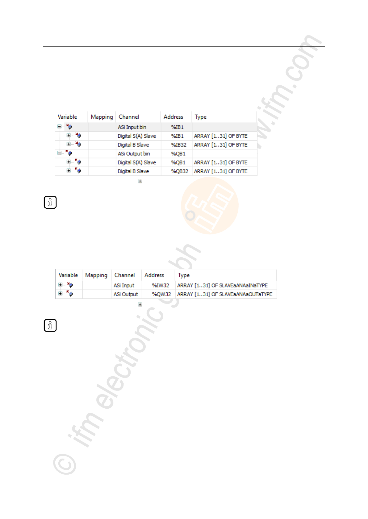
Digital input and output data
To access the digital process data of the slaves at AS-i master 1:
► In the device tree: Double click on [ASi_1_binaryIO]
> The editor window shows a structured list of the digital inputs and outputs of the AS-i slaves.
► In column [Variable]: Mouse click on to make individual variables visible.
>
Analogue input and output data
To access the analogue process data of the slaves at AS-i master 1:
► In the device tree: Double-click on [ASi_1_analogIO]
> Editor window shows a structured list of the analogue inputs and outputs of the AS-i slaves.
17625
17626
► In column [Variable]: Mouse click on to make individual variables visible.
30
Page 31

ifm Programming Manual AS-i Gateway AC14 (4.2.x) 12/2017
Programming Access input and output data
>
1
Data that the fieldbus transmits/receives via the fieldbus.
→ Input and output data of the fieldbus interface (→ p. 31)
2
Output data of the AS-i slaves at AS-i master 1 and AS-i master 2 that is transmitted by the higher-level fieldbus
PLC.
→ Outputs data of the AS-i slaves (→ p. 32)
Consider validity of the interface data (→ Validity of the interface data (→ p. 28))!
7.3.4 Fieldbus data
The device tree offers direct access to the data that is transmitted between fieldbus and device.
>
17585
Input and output data of the fieldbus interface
The input and output data of the fieldbus interface os transmitted in cycles of 120 words each. The
programmer can access this data via IEC addresses.
To access the input and output data of the fieldbus interface:
► Device window: In the project tree, double-click on [FieldBusData_]
> Editor window shows a structured list of the inputs and outputs:
► In column [Variable]: Mouse click on to make individual variables visible.
17619
31
Page 32

ifm Programming Manual AS-i Gateway AC14 (4.2.x) 12/2017
Programming Access input and output data
>
If the output access of the device is set to "PLC", the programmer can use the data bundled in
this area to process the target values sent by the higher-level fieldbus controller to the
CODESYS PLC.
To access the digital output data of the slaves at AS-i master 2 in a system with 2 AS-i masters:
► Double-click on [ASi_2_binaryIO]
To access the analogue output data of the slaves at AS-i master 2 in a system with 2 AS-i masters:
► Double-click on [ASi_2_analogOut]
Output data of the AS-i slaves
17620
The area contains all data, the higher-level Fieldbus controller cyclically sends to the outputs of the
AS-i slaves via the fieldbus network. The data is structure like an AS-i network. The programmer can
access this data via IEC addresses.
>
Digital output data
17630
To access the digital output data of the slaves at AS-i master 1:
► Device window: In the project tree, double-click on [ASi_1_binaryIO]
> Editor window shows a structured list of the digital output data:
► In column [Variable]: Mouse click on to make individual variables visible.
>
Analogue output data
To access the analogue output data of the slaves at AS-i master 1:
► Device window: In the project tree, double-click on [ASi_1_analogOut]
> Editor window shows the structured list of the analogue output data:
► In column [Variable]: Mouse click on to make individual variables visible.
17631
32
Page 33

ifm Programming Manual AS-i Gateway AC14 (4.2.x) 12/2017
Programming Use functions of the ifm package
>
Designation
Type
Data type
Description
Possible values
xExecute
Input
BOOL
Control FB execution
FALSE
Stop FB execution
TRUE
Start FB execution
xReady
Output
BOOL
Indication of whether execution of
the FB has been completed
FALSE
FB execution not yet completed
TRUE
FB execution completed
xBusy
Output
BOOL
Indication of whether FB is active
FALSE
Function block is inactive
TRUE
FB is active
xError
Output
BOOL
Indication of whether faults have
occurred during execution of the
FB
FALSE
FB executed correctly
TRUE
Error occurred during execution of
the FB
wDiagnostic
Output
WORD
Error code
FB specific
7.4 Use functions of the ifm package
18489
The CODESYS package "CODESYS for ifm SmartPLC StandardLine" offers different functions for the
programming of the device-internal CODESYS controller. In the following sections, these functions will
be briefly described. To make orientation easier, the functions are grouped according to corresponding
subjects and provided with a cross-reference to a detailed explanation in the document's appendix.
>
7.4.1 Control interface of the ifm function blocks
17660
All function blocks (FB) of the libraries ACnnnn_Utils.library and ACnnnn_SYS_CMD.library have
inputs and outputs for control signals. The inputs activate the execution of the function block. The
outputs provide information about the internal condition of the function block. Thanks to the signals,
the programmer can create a control structure for a targeted processing of the FB and react to
possible errors.
Number and designation of the FB control signals provide information about the type of FB execution:
>
FB with one-time execution
17140
These function blocks perform their function exactly once after activation. To execute the function
once again, the FB needs to be reactivated. FBs of this kind feature a control interface with the
following inputs and outputs:
The following figure shows the relation between the connections of the control signals:
33
Page 34

ifm Programming Manual AS-i Gateway AC14 (4.2.x) 12/2017
Programming Use functions of the ifm package
1
xExecute = TRUE:
xBusy = TRUE:
Rising edge (FALSE TRUE) starts execution of the FB.
FB execution has been started, but has not yet been completed.
2
xReady = TRUE:
xBusy = FALSE:
xError = FALSE:
FB execution completed; there are valid values on the data outputs.
FB is no longer active.
FB execution without faults.
3
xExecute = FALSE:
All signal outputs are set to FALSE and all internal states are reset.
4
→ 1
5
xReady = TRUE:
xBusy = FALSE:
xError = TRUE:
FB execution is terminated.
FB is no longer active.
Errors occurred during FB execution; wDiagnostic provides error code.
6
→ 3
7
→ 1
8
xExecute = FALSE:
FB execution interrupted prior to completion; All signal outputs are set to FALSE and all
internal states are reset.
Designation
Type
Data type
Description
Possible values
xEnable
Input
BOOL
Control FB execution
FALSE
Stop FB execution
TRUE
Start FB execution
xActive
Output
BOOL
Indication of whether execution of
the FB has been completed
FALSE
FB execution not yet completed
TRUE
FB execution completed
xError
Output
BOOL
Indication of whether faults have
occurred during execution of the
FB
FALSE
FB executed correctly
TRUE
Error occurred during execution of
the FB
wCycleCount
Output
WORD
Counters for the FB cycles
Integer value (hexadecimal representation)
wDiagnostic
Output
WORD
Error code
FB specific
>
FB with cyclic execution
17141
Function blocks which, when activated, cyclically perform their function until they are deactivated have
the following control inputs and outputs:
34
Page 35

ifm Programming Manual AS-i Gateway AC14 (4.2.x) 12/2017
Programming Use functions of the ifm package
>
Name
Description
Reference
QuickSetupASi_Master
Execute quick setup routine on an AS-i master
→ QuickSetupASi_Master (→ p. 109)
Set_TimeDate
Set system time (date, time) of the system
→ Set_TimeDate (→ p. 111)
Get_FieldbusInfo
Read fieldbus type, the status of the field bus connection
and the parameters of the fieldbus interface
→ Get_FieldbusInfo (→ p. 107)
Name
Description
Reference
Set_Mode
Set operating mode of the AS-i master (projecting mode
or protected operation)
→ Set_Mode (→ p. 93)
Set_ASi_Config
Set diagnostic functions of the AS-i master (double
address recognition, earth fault detection)
→ Set_ASi_Config (→ p. 89)
Set_AdressMode
Set automatic addressing of the AS-i master
→ Set_AddressMode (→ p. 87)
Name
Description
Reference
Set_SlaveAddress
Change address of an AS-i slave
→ Set_SlaveAddress (→ p. 98)
Set_SlaveParameter
Change I/O configuration and ID codes (IO, ID, ID1, ID2)
of an AS-i slave
→ Set_SlaveParameter (→ p. 102)
Set_SlaveExtendedID1
Extended ID1 of an AS-i slave
→ Set_SlaveExtendedID1 (→ p. 100)
7.4.2 Configure system
To configure the system of the device, use the following function blocks:
>
7.4.3 Configure AS-i master
To configure the AS-i masters of the device, use the following function blocks:
17450
17448
>
7.4.4 Configure AS-i slaves
To configure the AS-i slaves, that are connected to the device, use the following function blocks:
17449
35
Page 36

ifm Programming Manual AS-i Gateway AC14 (4.2.x) 12/2017
Programming Use functions of the ifm package
>
Name
Description
Reference
ASI_NET
The complex variable contains the complete process image
(inputs and outputs) of an AS-i network.
→ ASI_NET (STRUCT) (→ p. 117)
ASI_DATA
The complex variable contains the following components:
Slave lists (LPS, LDS, LAS, LPF, LCE, LCEMS, LCEAS,
LDAE)
Parameter images (PI, PP)
Configuration data of the AS-i slaves (CDI, PCD)
→ ASI_DATA (STRUCT) (→ p. 115)
→ Get_ASi_Data (→ p. 104)
Name
Description
Reference
Set_ProjectAll
Execute projection adaptation on one AS-i master
→ Set_ProjectAll (→ p. 97)
Set_LPS
Change list of the projected slaves (LDS)
→ Set_LPS (→ p. 91)
Set_PCD
Change permanent projecting data (IO, ID, ID1, ID2) of
all slaves on the AS-i master
→ Set_PCD (→ p. 95)
7.4.5 Manage AS-i network
17126
To manage the AS-i networks controlled by AS-i Gateway AC14, use the following function blocks:
>
Use complex variables
18528
There are different complex variables (STRUCT) at the programmer's disposal. They bundle logically
associated data sets. Thereby, they facilitate the organisation of the data storage in the application
and at the same time reduce the error rate when variables are declared.
The following complex variables are available:
>
Change network settings
17568
36
Page 37

ifm Programming Manual AS-i Gateway AC14 (4.2.x) 12/2017
Programming Use functions of the ifm package
>
Name
Description
Reference
Get_ASi_Data
Read the following datasets for network management in
batches and cycles:
List of activated slaves (LAS)
List of detected slaves (LDS)
List of projected slaves (LPS)
List of peripheral faults (LPF)
List of configuration errors (LCE)
List of configuration errors, missing slaves (LCEMS)
List of configuration errors - additional slaves
(LCEAS)
List of double address errors (LDAE)
Configuration data image (CDI)
Permanent configuration data (PCD)
Input parameters (PI)
Output parameters (PP)
→ Get_ASi_Data (→ p. 104)
Name
Description
Reference
Get_InputParameter
Read parameters of the inputs of the slaves at the AS-i
master (PI)
→ Get_InputParameter (→ p. 83)
Get_OutputParameter
Read parameters of the outputs of the slaves on the
AS-i master (PP)
→ Get_OutputParameter (→ p. 85)
Name
Description
Reference
Get_LPS
Read list of projected slaves (LPS)
→ Get_LPS (→ p. 67)
Get_LDS
Read list of detected slaves (LDS)
→ Get_LDS (→ p. 65)
Get_LAS
Read list of activated slaves (LAS)
→ Get_LAS (→ p. 63)
Get_LPF
Read list of peripheral faults (LPF)
→ Get_LPF (→ p. 77)
Get_LCE
Read list of configuration errors (LCE)
→ Get_LCE (→ p. 69)
Get_LCEMS
List of configuration errors - read missing slaves
(LCEMS)
→ Get_LCEMS (→ p. 73)
Get_LCEAS
Read of the configuration errors - read additional slave
(LCEAS)
→ Get_LCEAS (→ p. 71)
Get_LDAE
Read list of double address errors (LDAE)
→ Get_LDAE (→ p. 75)
Read network settings
To read the network settings cyclically and offer them in the application:
Alternatively, this data can be read separately with the following FB:
>
18532
Read parameter images
>
read slave lists
17569
18530
37
Page 38

ifm Programming Manual AS-i Gateway AC14 (4.2.x) 12/2017
Programming Use functions of the ifm package
>
Name
Description
Reference
Get_CDI
Read configuration data image (IO, ID, ID1, ID2) of all
slaves on the AS-i master
→ Get_CDI (→ p. 79)
Get_PCD
Read permanent configuration data of all slaves (IO, ID,
ID1, ID2) on the AS-i master
→ Get_PCD (→ p. 81)
Name
Description
Reference
Get_ASi_PHY_Dat
Determine voltage supply status of the AS-i network
→ Get_ASi_PHY_Dat (→ p. 61)
Read configuration data of the slaves
>
Read status of the voltage supply
18533
18529
38
Page 39

ifm Programming Manual AS-i Gateway AC14 (4.2.x) 12/2017
Programming Use functions of the ifm package
>
By default, the FB ACnnnn_SysCmd is hidden. To add the FB to a program module:
► Highlight the required network and add an empty function block with [FBD/LD/IL] > [Insert Empty Block].
> Network shows empty FB.
► Double-click on the name field of the FB
► Enter designation ACnnnn_SysCmd and
confirm with [ENTER].
> FB has inputs and outputs of the
ACnnnn_SysCmd.
► Adjust inputs and outputs of the FB in
accordance with the required command.
7.4.6 Send commands to the system and the AS-i master
Similar to the acyclic transmission command channels and data sets of the device, the programmer
can send commands to the system or an AS-i master with the FB ACnnnn_SysCmd
(→ ACnnnn_SysCmd (→ p. 121)).
System command overview: → Table: System commands (→ p. 122)
Overview AS-i master commands: → Table: AS-i master commands (→ p. 123)
17659
39
Page 40

ifm Programming Manual AS-i Gateway AC14 (4.2.x) 12/2017
Programming Use visualisations
>
Supported visualisation types .................................................................................................................40
Add visualisation to a project ..................................................................................................................41
Create a visualisation .............................................................................................................................42
Configure visualisation ...........................................................................................................................43
► Familiarise yourself with the following CODESYS functions!
Visualisations in CODESYS
→ Online help > CODESYS visualisation
7.5 Use visualisations
>
7.5.1 Supported visualisation types
The AS-i Gateway AC14 supports the following CODESYS visualisation types:
Web visualisation (WebVisu)
A WebVisu allows graphic representation of selected process and control data of the device in a
web browser by means of a user-specific visualisation.
Target visualisation (TargetVisu)
A TargetVisu allows graphic representation of selected process and control data of the device on
the display of the device by means of a user-specific visualisation.
17059
17661
40
Page 41

ifm Programming Manual AS-i Gateway AC14 (4.2.x) 12/2017
Programming Use visualisations
>
1
[VISU_TASK] provides access to the visualisation task properties (→ Set parameters for visualisation task
(→ p. 45))
2
[Visualization Manager] provides access to the visualisation properties (→ Configure visualisation (→ p. 43))
3
[MyVisu] contains the area for the creation of the visualisation objects (→ Create a visualisation (→ p. 42))
7.5.2 Add visualisation to a project
To add a visualisation to a CODESYS project:
► Open CODESYS project.
OR:
Create new CODESYS project. (→ Create new project with AS-i Gateway AC14 (→ p. 17))
► In the device tree: Click on [Application].
► Select [Project] > [Add Object] > [Visualization...]
> [Add Visualization] window appears.
► Enter a designation for the visualization in the [Name] field and click on [Add] to apply.
> CODESYS adds the following elements to the device tree:
17060
41
Page 42

ifm Programming Manual AS-i Gateway AC14 (4.2.x) 12/2017
Programming Use visualisations
>
Create a seperate visualisation object for each target and web visualisation.
7.5.3 Create a visualisation
To create a visualisation for a PLC application:
► In the device tree: double-click on [Visualization]
> The visualisation editor with a tool box appears:
17061
► Create the visualisation using the tools.
► Save the project to apply changes.
42
Page 43

ifm Programming Manual AS-i Gateway AC14 (4.2.x) 12/2017
Programming Use visualisations
>
In the field [Name of .htm file] enter the name by which the web visualisation is to be accessible in the web
browser (→ Display web visualisation (→ p. 56)).
► Use only lower case when entering the name!
7.5.4 Configure visualisation
In order to change the properties of the created visualisations, choose one of the following options:
Change properties of the web visualisation (→ p. 43)
Change the properties of the target visualisation (→ p. 44)
>
Change properties of the web visualisation
To change the attributes of the web visualisation:
► In device tree: Double click on [Web-Visualisierung]
> The editor window shows attributes of the web visualisation:
6953
17065
► Set the following values:
1. Field [Start Visualization]: Select the created web visualisation.
2. Field [Name of .htm file]: Enter name for HTML file (→ Note).
3. Area [Scaling Options]: Enter fixed width and height as shown.
► Save the project to apply changes.
43
Page 44

ifm Programming Manual AS-i Gateway AC14 (4.2.x) 12/2017
Programming Use visualisations
>
Change the properties of the target visualisation
To change the properties of the target visualisation:
► In device tree: Double-click on [TargetVisu]
> Editor window shows properties of the target visualisation.
17064
► Set the following values:
1. [Start Visualization] field: Select the created target visualisation.
2. [Scaling options] area: Enter fixed width and height as illustrated.
► Save the project to apply changes.
44
Page 45

ifm Programming Manual AS-i Gateway AC14 (4.2.x) 12/2017
Programming Configure task processing
>
► Familiarise yourself with the following CODESYS functions!
Task configuration
→ Online help > CODESYS Development System > application programmable > task
configuration
Name
Description
Note
[MainTask]
Configuration of the main task (e.g. for main program
[PLC_PRG (PRG)])
→ Configure main task (→ p. 45)
[VISU_TASK]
Configuration of the task for processing visualisation
→ Set parameters for visualisation task
(→ p. 45)
► Execute the visualisation task (VISU_TASK) with a priority that is as low as possible to
avoid interruption of other tasks that are important for the core functions of the application.
► Execute the VISU_TASK in appropriate cyclic intervals to save the resources of the
device-internal CODESYS PLC of the fieldbus network.
7.6 Configure task processing
The processing of the tasks is controlled by parameters. The user can set the parameters for each
task separately
CODESYS automatically creates the following tasks and visualisations during project creation:
>
4109
7.6.1 Configure main task
18412
The basic settings of the task characteristics cover the requirements of many applications. In the event
of non-optimum device performance the user must determine and set the optimum task characteristics
himself.
To change parameters of a task:
► In device tree: Double click on [Taskkonfiguration] > [MainTask]
> The editor window shows the configuration of the main task.
► Set the parameters as requested.
> Selected value is applied.
>
7.6.2 Set parameters for visualisation task
17066
Each visualisation is executed separately from the program code in a separate task. To set the
properties of the visualisation task:
► In the device tree: Double-click on [Task configuration] > [VISU_TASK]
> Editor window shows parameters of the visualisation task.
► Set the parameters as required.
► Save the project to apply changes.
45
Page 46

ifm Programming Manual AS-i Gateway AC14 (4.2.x) 12/2017
Programming Testing the PLC application
>
► Familiarise yourself with the following CODESYS functions!
Test and fault elimination
→ Online help > CODESYS Development System > Testing and Debugging
7.7 Testing the PLC application
18594
To ensure permanent operation without errors in industrial environments, the created PLC application
must be tested in detail and possible faults must be remedied.
46
Page 47

ifm Programming Manual AS-i Gateway AC14 (4.2.x) 12/2017
Operation Testing the PLC application
8 Operation
Transfer CODESYS project to device ....................................................................................................48
Operating states of the PLC ...................................................................................................................52
Reset ......................................................................................................................................................54
Display web visualisation ........................................................................................................................56
Display target visualisation .....................................................................................................................57
18492
47
Page 48

ifm Programming Manual AS-i Gateway AC14 (4.2.x) 12/2017
Operation Transfer CODESYS project to device
>
Activate CODESYS PLC ........................................................................................................................49
Download the application to the device ..................................................................................................50
Delete application from AS-i Gateway AC14 ..........................................................................................50
Delete boot application via SD card .......................................................................................................51
► Familiarise yourself with the following CODESYS functions!
Compile project/application and transfer it to device
→ Online help > CODESYS Development System > Transferring Applications to the
PLC
► Observe notes on the operating modes of the PLC of the device!
→ Operating states of the PLC (→ p. 52)
ifm system solutions and CODESYS applications created by the user must not be saved and
executed on the device at the same time!
► Before loading an application to the device delete all ifm system solutions saved on the
device (→ Device manual, Uninstall ifm apps)!
To be able to use an ifm system solution in a user project the functions must be integrated into
the project via libraries to be ordered separately.
► Contact the AS-i specialist of ifm electronic!
8.1 Transfer CODESYS project to device
To save the CODESYS project on the device the following component must be transferred to the
device:
application "Application" (→ Download the application to the device (→ p. 50))
18490
48
Page 49

ifm Programming Manual AS-i Gateway AC14 (4.2.x) 12/2017
Operation Transfer CODESYS project to device
>
List
[Output access]
Checkbox
[Use PLC]
CODESYS PLC
Programmable
Access to
AS-i inputs
Access to
AS-i outputs
Gateway
no
yes
no yes
yes
no
Manual
no
yes
no
yes
yes
no
PLC
*
yes
yes
yes
Legend:
* ...
Value fixed (greyed out)
8.1.1 Activate CODESYS PLC
17692
To enable the processing of the created PLC application, the device-internal CODESYS PLC must be
activated in the setup menu of AS-i Gateway AC14.
If the PLC application is to have a write access to the outputs of the AS-i slaves, the CODESYS PLC
must be activated additionally as controller instance of the AS-i slave outputs.
The following table shows the possible combinations of the parameters [Output access] and [Use PLC]
as well as the rights of the CODESYS PLC resulting thereof.
To set the operating mode of the device:
1 Select menu page
► >
► Select [System settings] tab.
2 Set the controller instance of the outputs
► Select the requested controller instance of the AS-i outputs in the [Output access] list.
► Press [Accept selection] to activate the selection.
3 Activate CODESYS PLC
► Activate [Use PLC] checkbox.
> CODESYS PLC is active.
4 Optional: Adjust device cycle
► Select the requested device cycle time in the [Device cycle] list.
► Press [Accept selection] to activate the selected value.
49
Page 50

ifm Programming Manual AS-i Gateway AC14 (4.2.x) 12/2017
Operation Transfer CODESYS project to device
>
8.1.2 Download the application to the device
To transfer the created application as boot project to the device:
Requirements:
> Network path is set (→ Set communication path to PLC (→ p. 20)).
> Project tested.
> All ifm system solutions stored on the devie are deleted (→ device manual: Uninstall ifm apps)
1 Build application
► In the device tree: Highlightt application as active application.
► Use [Build] > [Rebuild] to compile the active application.
> CODESYS generates program code.
2 Load application on the device
► Use [Online] > [Login] to connect with the device.
> Active application is transfered to the device (download).
> application on the device is in STOP state.
3 Create boot application
► Use [Online] > [Create boot application] to make the application bootable.
> application storage is non-volatile.
4 Start boot application
► Use [Debug] > [Start] to start the application.
> application goes to the RUN state.
>
18593
8.1.3 Delete application from AS-i Gateway AC14
To delete an application stored on the device:
1 Connect with the device
► In the device tree: highlight application as active application.
► Use [Online] > [Login] to establish connection to the device.
> CODESYS is in the online mode.
2 Delete application
► In the editor window: Select [Device] > [Applications] tab.
► Press [Refresh List] to refresh the view.
> List shows the applications that are stored on the device.
► Delete all applications in the device with [Remove All].
OR:
Highlight requested application and press [Remove] to delete it from the device.
> Selected application will be deleted.
18030
50
Page 51

ifm Programming Manual AS-i Gateway AC14 (4.2.x) 12/2017
Operation Transfer CODESYS project to device
>
With this method the following data on the device-internal PLC is removed:
all files of the boot application
all CRC files
directory with web and/or target visualisations
data in the memory area F-RAM
8.1.4 Delete boot application via SD card
15970
If after the start of a complex boot application the device is overloaded and does not respond any
more to user inputs or login attempts, the boot application on the device needs to be forcibly deleted.
To delete the boot application on the device:
► Disable the write protection of the SD card.
► Create a file named KillBootApp.txt in the root directory of the SD card.
► Insert the SD card into the SD card slot of the device.
► Restart the device.
> Boot application on the device-internal PLC is deleted.
> The file KillBootApp.txt on the SD card is renamed in KillBootApp.rdy.
51
Page 52

ifm Programming Manual AS-i Gateway AC14 (4.2.x) 12/2017
Operation Operating states of the PLC
>
8.2 Operating states of the PLC
17544
This section provides information about the operating states of the device and the states of the PLC of
the device as well as information about the states of the applications.
>
8.2.1 Operating mode of the PLC
13769
The PLC of the device can be operated in the following modes:
Offline mode
In the offline mode the user is logged out of the PLC or there is no connection between CODESYS
and the PLC (e.g. connection loss).
Online mode
In the online mode the user is logged in to the PLC.
>
8.2.2 States of the PLC application
4136
The applications saved on the device are executed independently in separate tasks. A application can
have the following states:
Unload
No application is saved on the PLC.
RUN
The application is executed (cyclically processed).
STOP
The application is not executed.
>
Display operating state of the application
To display the current operating state of the PLC choose one of the following options:
CODESYS:
> In the device tree: Node of the application indicates the current state.
OR:
> In online mode the CODESYS status bar shows the current state of the application.
GUI / web interface of the device:
► > >
► Select the [Applications] tab.
> The page displays the operating states of the PLC applications saved on the device.
10272
52
Page 53

ifm Programming Manual AS-i Gateway AC14 (4.2.x) 12/2017
Operation Operating states of the PLC
>
8.2.3 Switch operating states
To switch between the operating states of the application choose one of the following options:
>
Start PLC application
To start a PLC application stored on the device:
CODESYS:
► In the device tree: highlight application as active application.
► Use [Online] > [Login] to establish the connection with the CODESYS PLC.
► Use [Debug] > [Start] to start the processing of the active application.
> Application goes to RUN state.
► Optional: repeat process for additional applications.
GUI / web interface:
► > >
► Select the [Applications] tab.
► Use [] / [] to select the required application.
> Page shows the operating status of the selected application.
► Press [Start] function key to start the processing of the selected application.
> Application goes to RUN state.
► Optional: repeat process for additional applications.
>
10264
18027
Stop PLC application
To stop a PLC application stored on the device:
CODESYS:
► In the device tree: highlight application as active application.
► Use [Online] > [Login] to establish the connection with the CODESYS PLC.
► Use [Debug] > [Stop] to stop the processing of the active application.
> Application goes to STOP state.
► Optional: repeat process for additional applications.
GUI / web interface:
► > >
► Select [Applications] tab.
► Use [] / [] to select the required application.
> Page shows the operating status of the selected application.
► Press [Stop] function key to stop the processing of the selected application.
> Application goes to STOP state.
► Optional: repeat process for additional applications.
18029
53
Page 54

ifm Programming Manual AS-i Gateway AC14 (4.2.x) 12/2017
Operation Reset
>
Supported reset variants ........................................................................................................................54
Reset the application (warm) ..................................................................................................................55
Reset the application (cold) ....................................................................................................................55
Reset the application (origin) ..................................................................................................................55
Type of reset
System behaviour
Triggering actions
Reset (warm)
application goes to STOP state.
Standard variables (VAR) of the application are
initialised.
Remanent variables (VAR RETAIN) of the
application keep their current values.
→ Reset the application (warm) (→ p. 55)
Reset (cold)
application changes to the STOP state.
All variables (VAR, VAR RETAIN) of the
application are initialised.
→ Reset the application (cold) (→ p. 55)
Reset (default)
application goes to STOP state.
The application on the PLC is deleted.
All variables (VAR, VAR RETAIN) of the
application are initialised.
PLC is reset to the default state.
→ Reset the application (origin) (→ p. 55)
A variable that has been declared without an initialisation value is initialised with the
variable-specific standard value (e.g. INT = 0).
8.3 Reset
>
18025
8.3.1 Supported reset variants
18613
The following table shows the reset variants supported by the device-internal CODESYS PLC and the
resulting system behaviour:
54
Page 55

ifm Programming Manual AS-i Gateway AC14 (4.2.x) 12/2017
Operation Reset
>
8.3.2 Reset the application (warm)
To reset the application on the PLC, choose one of the following options:
CODESYS: command [Reset (warm)]
► In the device tree:
Highlight the required application as active application.
► Select [Online] > [Login] to establish a connection to the CODESYS PLC.
> CODESYS switches to online mode.
► Select [Online] > [Reset warm] to reset the application.
GUI: command [Reset]
► >
► Select [All Applications] tab.
► Use [Reset] to reset all applications.
GUI: command [Restart]
► >
► Select [System-reset] tab.
► Use [Restart] to reboot the device.
>
13131
9069
8.3.3 Reset the application (cold)
To reset the application on the PLC, choose one of the following options:
Download the application to the device
► → Download the application to the device (→ p. 50)
CODESYS: command "Reset (cold)"
► In the device tree:
Highlight the required application as active application.
► Select [Online] > [Login] to establish a connection to the CODESYS PLC.
> CODESYS switches to online mode.
► Select [Online] > [Reset cold] to reset the application.
>
8.3.4 Reset the application (origin)
To reset the application on the PLC:
CODESYS: command "Reset (origin)"
► In the device tree:
Highlight the required application as active application.
► Select [Online] > [Login] to establish a connection to the CODESYS-PLC.
> CODESYS switches to online mode.
► Select [Online] > [Reset origin] to reset the application.
15687
18962
55
Page 56

ifm Programming Manual AS-i Gateway AC14 (4.2.x) 12/2017
Operation Display web visualisation
>
myvisu is the user-defined name of the visualisation (→ Change properties of the web visualisation
(→ p. 43)).
8.4 Display web visualisation
To display the created web visualisation:
Requirements:
> PC/laptop is connected to the configuration interface (X3) of the device (→ device manual: Configuration
interface: connection concepts)
CODESYS PLC appliation
► Download PLC application with web visualisation to the device and start it (→ Download the application to the
device (→ p. 50)).
► On PC/laptop: Start web browser.
► Enter the following in the address line and press [ENTER] to confirm:
<IP address-of-the-device>:<8080>/myvisu.htm
> Web browser shows the web visualisation of the device.
ifm system solution
► Install the ifm system solution on the device and start it (→ device manual, Install single/basic app or Install
multi app).
► Display informationen about the installed ifm app (→ device manual, Show information about installed ifm
apps).
► Call hyperlink of the ifm app.
> Web browser shows the web visualisation of the ifm system solution.
17063
56
Page 57

ifm Programming Manual AS-i Gateway AC14 (4.2.x) 12/2017
Operation Display target visualisation
>
If the device does not react to the pressing of [] + [], the key combination is deactivated.
► Activate the key combination with the system command [Display target visualisation].
After a restart of the device the menu view of the GUI appears by default.
► With the FB ACnnnn_SysCmd (→ p. 121)execute the system command [Display target
visualisation] at the start of the PLC application.
Further information: → Device manual: Command 0x0110 – Display target visualisation"
8.5 Display target visualisation
After compilation of the project and download to the device the user has to start the target
visualisation:
CODESYS / higher-level Fieldbus controller:
► Execute system command [Display target visualisation] (→ Device manual, Command 0x0110 – Display target
visualisation)
GUI / web interface:
► Activate target visualisation via the menu (→ Device manual: Show target visualisation)
OR:
Switch between target visualisation and menu with the key combination [] + [].
20256
57
Page 58

ifm Programming Manual AS-i Gateway AC14 (4.2.x) 12/2017
Appendix Display target visualisation
9 Appendix
Library ACnnnn_Utils.library ...................................................................................................................59
Library ACnnnn_SYS_CMD.library ......................................................................................................121
7156
58
Page 59

ifm Programming Manual AS-i Gateway AC14 (4.2.x) 12/2017
Appendix Library ACnnnn_Utils.library
>
Overview: AS-i functions (FB_ASi) .........................................................................................................60
Overview: System functions (FB_System) ...........................................................................................106
Enumeration types and complex variables ...........................................................................................113
9.1 Library ACnnnn_Utils.library
17722
59
Page 60

ifm Programming Manual AS-i Gateway AC14 (4.2.x) 12/2017
Appendix Library ACnnnn_Utils.library
>
Get_ASi_PHY_Dat .................................................................................................................................61
Get_LAS .................................................................................................................................................63
Get_LDS .................................................................................................................................................65
Get_LPS .................................................................................................................................................67
Get_LCE .................................................................................................................................................69
Get_LCEAS ............................................................................................................................................71
Get_LCEMS ...........................................................................................................................................73
Get_LDAE...............................................................................................................................................75
Get_LPF .................................................................................................................................................77
Get_CDI ..................................................................................................................................................79
Get_PCD ................................................................................................................................................81
Get_InputParameter ...............................................................................................................................83
Get_OutputParameter ............................................................................................................................85
Set_AddressMode ..................................................................................................................................87
Set_ASi_Config ......................................................................................................................................89
Set_LPS..................................................................................................................................................91
Set_Mode ...............................................................................................................................................93
Set_PCD .................................................................................................................................................95
Set_ProjectAll .........................................................................................................................................97
Set_SlaveAddress ..................................................................................................................................98
Set_SlaveExtendedID1 ........................................................................................................................100
Set_SlaveParameter ............................................................................................................................102
Get_ASi_Data .......................................................................................................................................104
9.1.1 Overview: AS-i functions (FB_ASi)
60
17459
Page 61

ifm Programming Manual AS-i Gateway AC14 (4.2.x) 12/2017
Appendix Library ACnnnn_Utils.library
>
Function block type:
Function block (FB)
Library:
ACnnnn_Utils.library
Symbol in CODESYS:
Parameter
Data type
Description
Possible values
xExecute
BOOL
Control execution of the FB
FALSE
Stop FB execution
TRUE
Start one-time FB execution
enASi_Master
ASI_MASTER
Select AS-i master
Master_1
AS-i master 1
Master_2
AS-i master 2
Get_ASi_PHY_Dat
>
Description
The FB reads the physical data of the selected AS-i master and provides the values.
>
16005
16040
Input parameters
16041
61
Page 62

ifm Programming Manual AS-i Gateway AC14 (4.2.x) 12/2017
Appendix Library ACnnnn_Utils.library
>
Parameter
Data type
Description
Possible values
xPS
BOOL
Voltage source (Power Source)
FALSE
Unit is supplied via Aux.
TRUE
Unit is supplied via AS-i.
xPM
BOOL
Power24-Modul (PM)
FALSE
Power24 module missing.
TRUE
Power24 module is inserted.
xEF
BOOL
Earth fault
FALSE
No earth fault
TRUE
Supply voltage is asymmetric,
earth fault suspected.
xSE
BOOL
Status of the earth fault detection
FALSE
Earth fault detection does not
provide valid data (e.g. when
AS-i voltage is lacking).
TRUE
Earth fault detection provides
valid data.
xPF1
BOOL
Voltage <22.5 V (power fail 22.5 V)
FALSE
No AS-i power fault (Classic
APF)
TRUE
AS-i power fail (Classic APF),
i.e. AS-i voltage is below
22.5 V
xPF2
BOOL
Voltage <19.0V (power fail 19V)
FALSE
No AS-i power fail (24V-APF)
TRUE
AS-i power fail (24V-APF), i.e.
AS-i voltage is below 19.0 V
wVoltage1
WORD
Voltage AS-i+ to AS-i- in mV
wVoltage2
WORD
Voltage FE to AS-i in mV
iSymmetry
INT
Symmetry in % (-100% ... +100%)
0xFF9C
...
0x0000
...
0x0064
-100%
...
0%
...
+100%
xReady
BOOL
Signal indicates if the execution of the
FB is terminated.
FALSE
FB is inactive or being
executed.
TRUE
FB execution is terminated.
xBusy
BOOL
Signal indicates if the FB is executed.
FALSE
FB is deactivated or FB
execution is terminated.
TRUE
FB execution is started but not
yet terminated.
xError
BOOL
Signal indicates if errors occurred
while the FB was executed.
FALSE
FB is disabled or presently
executed or FB was executed
without error.
TRUE
An error occurred when the FB
was executed.
wDiagnostic
WORD
Diagnostic information
→ List below (Diagnostic codes)
0x0000
No specific error is set
Output parameters
16042
Diagnostic codes:
62
Page 63

ifm Programming Manual AS-i Gateway AC14 (4.2.x) 12/2017
Appendix Library ACnnnn_Utils.library
>
Function block type:
Function block (FB)
Library:
ACnnnn_Utils.library
Symbol in CODESYS:
Parameter
Data type
Description
Possible values
xExecute
BOOL
Control execution of the FB
FALSE
Stop FB execution
TRUE
Start one-time FB execution
enASi_Master
ASI_MASTER
Select AS-i master
Master_1
AS-i master 1
Master_2
AS-i master 2
Get_LAS
>
Description
The FB reads the list of activated slaves (LAS) of the selected AS-i master and provides the values.
>
Input parameters
16008
16068
16069
63
Page 64

ifm Programming Manual AS-i Gateway AC14 (4.2.x) 12/2017
Appendix Library ACnnnn_Utils.library
>
Parameter
Data type
Description
Possible values
dwLAS_SA_Slaves
DWORD
List of the active S/A slaves. Each bit
represents an AS-i address:
Bit 0 (LSB) = address 0
...
Bit 31 (MSB) = address 31/31A
Per bit:
0
No single/A slave available
1
Single/A slave available
dwLAS_B_Slaves
DWORD
List of the active B slaves. Each bit
represents an AS-i address:
Bit 0 (LSB) = not used
Bit 1 = address 1B
...
Bit 31 (MSB) = address 31B
Per bit:
0
No B slave available
1
B slave available
xReady
BOOL
Signal indicates if the execution of the
FB is terminated.
FALSE
FB is inactive or being
executed.
TRUE
FB execution is terminated.
xBusy
BOOL
Signal indicates if the FB is executed.
FALSE
FB is deactivated or FB
execution is terminated.
TRUE
FB execution is started but not
yet terminated.
xError
BOOL
Signal indicates if errors occurred
while the FB was executed.
FALSE
FB is disabled or presently
executed or FB was executed
without error.
TRUE
An error occurred when the FB
was executed.
wDiagnostic
WORD
Diagnostic information
→ List below (Diagnostic codes)
0x0000
No specific error is set
0x0F01
Unknown error
0x0F02
Unknown/invalid target
0x0F03
Unknown command ID
0x0F04
Invalid parameters
0x0F05
Timeout during processing
Output parameters
16070
Diagnostic codes:
>
64
Page 65

ifm Programming Manual AS-i Gateway AC14 (4.2.x) 12/2017
Appendix Library ACnnnn_Utils.library
>
Function block type:
Function block (FB)
Library:
ACnnnn_Utils.library
Symbol in CODESYS:
Parameter
Data type
Description
Possible values
xExecute
BOOL
Control execution of the FB
FALSE
Stop FB execution
TRUE
Start one-time FB execution
enASi_Master
ASI_MASTER
Select AS-i master
Master_1
AS-i master 1
Master_2
AS-i master 2
Get_LDS
>
Description
The FB reads the list of detected slaves (LDS) of the selected AS-i master and provides the values.
>
Input parameters
16013
16118
16119
65
Page 66

ifm Programming Manual AS-i Gateway AC14 (4.2.x) 12/2017
Appendix Library ACnnnn_Utils.library
>
Parameter
Data type
Description
Possible values
dwLDS_SA_Slaves
DWORD
List of detected S/A slaves. Each bit
represents an AS-i address:
Bit 0 (LSB) = address 0
...
Bit 31 (MSB) = address 31/31A
Per bit:
0
no slave detected
1
slave detected
dwLDS_B_Slaves
DWORD
List of detected B slaves. Each bit
represents an AS-i address:
Bit 0 (LSB) = not used
Bit 1 = address 1B
...
Bit 31 (MSB) = address 31B
Per bit:
0
No slave detected
1
Slave detected
xReady
BOOL
Signal indicates if the execution of the
FB is terminated.
FALSE
FB is inactive or being
executed.
TRUE
FB execution is terminated.
xBusy
BOOL
Signal indicates if the FB is executed.
FALSE
FB is deactivated or FB
execution is terminated.
TRUE
FB execution is started but not
yet terminated.
xError
BOOL
Signal indicates if errors occurred
while the FB was executed.
FALSE
FB is disabled or presently
executed or FB was executed
without error.
TRUE
An error occurred when the FB
was executed.
wDiagnostic
WORD
Diagnostic information
→ List below (Diagnostic codes)
0x0000
No specific error is set
0x0F01
Unknown error
0x0F02
Unknown/invalid target
0x0F03
Unknown command ID
0x0F04
Invalid parameters
0x0F05
Timeout during processing
Output parameters
16120
Diagnostic codes:
>
66
Page 67

ifm Programming Manual AS-i Gateway AC14 (4.2.x) 12/2017
Appendix Library ACnnnn_Utils.library
>
Function block type:
Function block (FB)
Library:
ACnnnn_Utils.library
Symbol in CODESYS:
Parameter
Data type
Description
Possible values
xExecute
BOOL
Control execution of the FB
FALSE
Stop FB execution
TRUE
Start one-time FB execution
enASi_Master
ASI_MASTER
Select AS-i master
Master_1
AS-i master 1
Master_2
AS-i master 2
Get_LPS
>
Description
The FB reads the list of projected slaves (LPS) at the selected AS-i master and provides the values.
>
Input parameters
16015
16130
16131
67
Page 68

ifm Programming Manual AS-i Gateway AC14 (4.2.x) 12/2017
Appendix Library ACnnnn_Utils.library
>
Parameter
Data type
Description
Possible values
dwLPS_SA_Slaves
DWORD
List of the projected S/A slaves. Each
bit represents an AS-i address:
Bit 0 (LSB) = address 0
...
Bit 31 (MSB) = address 31/31A
Per bit:
0
Slave not projected
1
Slave projected
dwLPS_B_Slaves
DWORD
List of the projected B slaves. Each bit
represents an AS-i address:
Bit 0 (LSB) = not used
Bit 1 = address 1B
...
Bit 31 (MSB) = address 31B
Per bit:
0
slave not projected
1
slave projected
xReady
BOOL
Signal indicates if the execution of the
FB is terminated.
FALSE
FB is inactive or being
executed.
TRUE
FB execution is terminated.
xBusy
BOOL
Signal indicates if the FB is executed.
FALSE
FB is deactivated or FB
execution is terminated.
TRUE
FB execution is started but not
yet terminated.
xError
BOOL
Signal indicates if errors occurred
while the FB was executed.
FALSE
FB is disabled or presently
executed or FB was executed
without error.
TRUE
An error occurred when the FB
was executed.
wDiagnostic
WORD
Diagnostic information
→ List below (Diagnostic codes)
0x0000
No specific error is set
0x0F01
Unknown error
0x0F02
Unknown/invalid target
0x0F03
Unknown command ID
0x0F04
Invalid parameters
0x0F05
Timeout during processing
Output parameters
16132
Diagnostic codes:
>
68
Page 69

ifm Programming Manual AS-i Gateway AC14 (4.2.x) 12/2017
Appendix Library ACnnnn_Utils.library
>
Function block type:
Function block (FB)
Library:
ACnnnn_Utils.library
Symbol in CODESYS:
Parameter
Data type
Description
Possible values
xExecute
BOOL
Control execution of the FB
FALSE
Stop FB execution
TRUE
Start one-time FB execution
enASi_Master
ASI_MASTER
Select AS-i master
Master_1
AS-i master 1
Master_2
AS-i master 2
Get_LCE
>
Description
The FB reads the list of configuration errors (LCE) of the selected AS-i master and provides the
values.
>
Input parameters
16009
16075
16076
69
Page 70

ifm Programming Manual AS-i Gateway AC14 (4.2.x) 12/2017
Appendix Library ACnnnn_Utils.library
>
Parameter
Data type
Description
Possible values
dwLCE_SA_Slaves
DWORD
List of configuration errors of the S/A
slaves. Each bit represents an AS-i
address:
Bit 0 (LSB) = address 0
...
Bit 31 (MSB) = address 31/31A
Per bit:
0
No configuration error
1
Configuration error
dwLCE_B_Slaves
DWORD
List of configuration errors of the B
slaves. Each bit represents an AS-i
address:
Bit 0 (LSB) = not used
Bit 1 = address 1B
...
Bit 31 (MSB) = address 31B
Per bit:
0
No configuration error
1
Configuration error
xReady
BOOL
Signal indicates if the execution of the
FB is terminated.
FALSE
FB is inactive or being
executed.
TRUE
FB execution is terminated.
xBusy
BOOL
Signal indicates if the FB is executed.
FALSE
FB is deactivated or FB
execution is terminated.
TRUE
FB execution is started but not
yet terminated.
xError
BOOL
Signal indicates if errors occurred
while the FB was executed.
FALSE
FB is disabled or presently
executed or FB was executed
without error.
TRUE
An error occurred when the FB
was executed.
wDiagnostic
WORD
Diagnostic information
→ List below (Diagnostic codes)
0x0000
No specific error is set
0x0F01
Unknown error
0x0F02
Unknown/invalid target
0x0F03
Unknown command ID
0x0F04
Invalid parameters
0x0F05
Timeout during processing
Output parameters
16077
Diagnostic codes:
70
Page 71

ifm Programming Manual AS-i Gateway AC14 (4.2.x) 12/2017
Appendix Library ACnnnn_Utils.library
>
Function block type:
Function block (FB)
Library:
ACnnnn_Utils.library
Symbol in CODESYS:
Parameter
Data type
Description
Possible values
xExecute
BOOL
Control execution of the FB
FALSE
Stop FB execution
TRUE
Start one-time FB execution
enASi_Master
ASI_MASTER
Select AS-i master
Master_1
AS-i master 1
Master_2
AS-i master 2
Get_LCEAS
16010
>
Description
16098
The FB reads the list of existing but not projected slaves (List of Configuration Error – Additional Slave
= LCEAS) of the selected AS-i master and provides the values.
>
Input parameters
16099
71
Page 72

ifm Programming Manual AS-i Gateway AC14 (4.2.x) 12/2017
Appendix Library ACnnnn_Utils.library
>
Parameter
Data type
Description
Possible values
dwLCEAS_SA_Slaves
DWORD
List of configuration errors of the S/A
slaves. Each bit represents an AS-i
address:
Bit 0 (LSB) = address 0
...
Bit 31 (MSB) = address 31/31A
Per bit:
0
No configuration error additional slave
1
Slave exists, but not projected
dwLCEAS_B_Slaves
DWORD
List of configuration errors of the B
slaves. Each bit represents an AS-i
address:
Bit 0 (LSB) = not used
Bit 1 = address 1B
...
Bit 31 (MSB) = address 31B
Per bit:
0
No configuration error additional slave
1
Slave exists, but not projected
xReady
BOOL
Signal indicates if the execution of the
FB is terminated.
FALSE
FB is inactive or being
executed.
TRUE
FB execution is terminated.
xBusy
BOOL
Signal indicates if the FB is executed.
FALSE
FB is deactivated or FB
execution is terminated.
TRUE
FB execution is started but not
yet terminated.
xError
BOOL
Signal indicates if errors occurred
while the FB was executed.
FALSE
FB is disabled or presently
executed or FB was executed
without error.
TRUE
An error occurred when the FB
was executed.
wDiagnostic
WORD
Diagnostic information
→ List below (Diagnostic codes)
0x0000
No specific error is set
0x0F01
Unknown error
0x0F02
Unknown/invalid target
0x0F03
Unknown command ID
0x0F04
Invalid parameters
0x0F05
Timeout during processing
Output parameters
16100
Diagnostic codes:
72
Page 73

ifm Programming Manual AS-i Gateway AC14 (4.2.x) 12/2017
Appendix Library ACnnnn_Utils.library
>
Function block type:
Function block (FB)
Library:
ACnnnn_Utils.library
Symbol in CODESYS:
Parameter
Data type
Description
Possible values
xExecute
BOOL
Control execution of the FB
FALSE
Stop FB execution
TRUE
Start one-time FB execution
enASi_Master
ASI_MASTER
Select AS-i master
Master_1
AS-i master 1
Master_2
AS-i master 2
Get_LCEMS
>
Description
The FB reads the list of projected but missing slaves (List of Configuration Error – Missing Slave =
LCEMS) at the selected AS-i master and provides the values.
>
Input parameters
16011
16106
16107
73
Page 74

ifm Programming Manual AS-i Gateway AC14 (4.2.x) 12/2017
Appendix Library ACnnnn_Utils.library
>
Parameter
Data type
Description
Possible values
dwLCEMS_SA_Slaves
DWORD
List of configured but missing S/A
slaves. Each bit represents an AS-i
address:
Bit 0 (LSB) = address 0
...
Bit 31 (MSB) = address 31/31A
Per bit:
0
No configuration error missing slave
1
Slave is projected but not
available
sdwLCEMS_B_Slaves
DWORD
List of the configured but non-existing
B slaves. Each bit represents an AS-i
address:
Bit 0 (LSB) = not used
Bit 1 = address 1B
...
Bit 31 (MSB) = address 31B
Per bit:
0
No configuration error missing slave
1
Slave is projected but not
available
xReady
BOOL
Signal indicates if the execution of the
FB is terminated.
FALSE
FB is inactive or being
executed.
TRUE
FB execution is terminated.
xBusy
BOOL
Signal indicates if the FB is executed.
FALSE
FB is deactivated or FB
execution is terminated.
TRUE
FB execution is started but not
yet terminated.
xError
BOOL
Signal indicates if errors occurred
while the FB was executed.
FALSE
FB is disabled or presently
executed or FB was executed
without error.
TRUE
An error occurred when the FB
was executed.
wDiagnostic
WORD
Diagnostic information
→ List below (Diagnostic codes)
0x0000
No specific error is set
0x0F01
Unknown error
0x0F02
Unknown/invalid target
0x0F03
Unknown command ID
0x0F04
Invalid parameters
0x0F05
Timeout during processing
Output parameters
16108
Diagnostic codes:
74
Page 75

ifm Programming Manual AS-i Gateway AC14 (4.2.x) 12/2017
Appendix Library ACnnnn_Utils.library
>
Function block type:
Function block (FB)
Library:
ACnnnn_Utils.library
Symbol in CODESYS:
Parameter
Data type
Description
Possible values
xExecute
BOOL
Control execution of the FB
FALSE
Stop FB execution
TRUE
Start one-time FB execution
enASi_Master
ASI_MASTER
Select AS-i master
Master_1
AS-i master 1
Master_2
AS-i master 2
Get_LDAE
16012
>
Description
16112
The FB reads the double address errors (LDAE) of the selected AS-i master and provides the values
in a list.
>
Input parameters
16113
75
Page 76

ifm Programming Manual AS-i Gateway AC14 (4.2.x) 12/2017
Appendix Library ACnnnn_Utils.library
>
Parameter
Data type
Description
Possible values
dwLDAE_SA_Slaves
DWORD
List of the double address errors.
Each bit represents an AS-i address:
Bit 0 (LSB) = address 0
...
Bit 31 (MSB) = address 31/31A
Per bit:
0
No double address error
1
Double address error
dwLDAE_B_Slaves
DWORD
List of double address errors. Each bit
represents an AS-i address:
Bit 0 (LSB) = not used
Bit 1 = address 1B
...
Bit 31 (MSB) = address 31B
Per bit:
0
No double address error
1
Double address error
xReady
BOOL
Signal indicates if the execution of the
FB is terminated.
FALSE
FB is inactive or being
executed.
TRUE
FB execution is terminated.
xBusy
BOOL
Signal indicates if the FB is executed.
FALSE
FB is deactivated or FB
execution is terminated.
TRUE
FB execution is started but not
yet terminated.
xError
BOOL
Signal indicates if errors occurred
while the FB was executed.
FALSE
FB is disabled or presently
executed or FB was executed
without error.
TRUE
An error occurred when the FB
was executed.
wDiagnostic
WORD
Diagnostic information
→ List below (Diagnostic codes)
0x0000
No specific error is set
0x0F01
Unknown error
0x0F02
Unknown/invalid target
0x0F03
Unknown command ID
0x0F04
Invalid parameters
0x0F05
Timeout during processing
Output parameters
16114
Diagnostic codes:
76
Page 77

ifm Programming Manual AS-i Gateway AC14 (4.2.x) 12/2017
Appendix Library ACnnnn_Utils.library
>
Function block type:
Function block (FB)
Library:
ACnnnn_Utils.library
Symbol in CODESYS:
Parameter
Data type
Description
Possible values
xExecute
BOOL
Control execution of the FB
FALSE
Stop FB execution
TRUE
Start one-time FB execution
enASi_Master
ASI_MASTER
Select AS-i master
Master_1
AS-i master 1
Master_2
AS-i master 2
Get_LPF
>
Description
The FB reads the list of peripheral faults (LPF) of the selected AS-i master and provides the values.
>
Input parameters
16014
16124
16125
77
Page 78

ifm Programming Manual AS-i Gateway AC14 (4.2.x) 12/2017
Appendix Library ACnnnn_Utils.library
>
Parameter
Data type
Description
Possible values
dwLPF_SA_Slaves
DWORD
List of peripheral faults on S/A slaves.
Each bit represents an AS-i address:
Bit 0 (LSB) = address 0
...
Bit 31 (MSB) = address 31/31A
Per bit:
0
No peripheral fault
1
Peripheral fault detected
dwLPF_B_Slaves
DWORD
List of peripheral faults on B slaves.
Each bit represents an AS-i address:
Bit 0 (LSB) = not used
Bit 1 = address 1B
...
Bit 31 (MSB) = address 31B
Per bit:
0
No peripheral fault
1
Peripheral fault detected
xReady
BOOL
Signal indicates if the execution of the
FB is terminated.
FALSE
FB is inactive or being
executed.
TRUE
FB execution is terminated.
xBusy
BOOL
Signal indicates if the FB is executed.
FALSE
FB is deactivated or FB
execution is terminated.
TRUE
FB execution is started but not
yet terminated.
xError
BOOL
Signal indicates if errors occurred
while the FB was executed.
FALSE
FB is disabled or presently
executed or FB was executed
without error.
TRUE
An error occurred when the FB
was executed.
wDiagnostic
WORD
Diagnostic information
→ List below (Diagnostic codes)
0x0000
No specific error is set
0x0F01
Unknown error
0x0F02
Unknown/invalid target
0x0F03
Unknown command ID
0x0F04
Invalid parameters
0x0F05
Timeout during processing
Output parameters
16126
Diagnostic codes:
78
Page 79

ifm Programming Manual AS-i Gateway AC14 (4.2.x) 12/2017
Appendix Library ACnnnn_Utils.library
>
Function block type:
Function block (FB)
Library:
ACnnnn_Utils.library
Symbol in CODESYS:
Parameter
Data type
Description
Possible values
xExecute
BOOL
Control execution of the FB
FALSE
Stop FB execution
TRUE
Start one-time FB execution
enASi_Master
ASI_MASTER
Select AS-i master
Master_1
AS-i master 1
Master_2
AS-i master 2
Get_CDI
>
Description
The FB reads the configuration data (Configuration Data Image = CDI) of the slaves at the selected
AS-i master and provides the values in an array. The configuration data of a slave consists of the
registers IO, ID, ID1 and ID2.
>
Input parameters
16006
16045
16046
79
Page 80

ifm Programming Manual AS-i Gateway AC14 (4.2.x) 12/2017
Appendix Library ACnnnn_Utils.library
>
Parameter
Data type
Description
Possible values
awCDI
ARRAY [0...63]
OF WORD
Configuration data of the slaves at the
selected AS-i master
Per Word:
Bits 0...3: I/O-Code
Bits 4...7: ID-Code
Bits 8...11: ID1-Code
Bits 12...15: ID2-Code
xReady
BOOL
Signal indicates if the execution of the
FB is terminated.
FALSE
FB is inactive or being
executed.
TRUE
FB execution is terminated.
xBusy
BOOL
Signal indicates if the FB is executed.
FALSE
FB is deactivated or FB
execution is terminated.
TRUE
FB execution is started but not
yet terminated.
xError
BOOL
Signal indicates if errors occurred
while the FB was executed.
FALSE
FB is disabled or presently
executed or FB was executed
without error.
TRUE
An error occurred when the FB
was executed.
wDiagnostic
WORD
Diagnostic information
→ List below (Diagnostic codes)
0x0000
No specific error is set
0x0F01
Unknown error
0x0F02
Unknown/invalid target
0x0F03
Unknown command ID
0x0F04
Invalid parameters
0x0F05
Timeout during processing
Output parameters
Diagnostic codes:
16047
>
80
Page 81

ifm Programming Manual AS-i Gateway AC14 (4.2.x) 12/2017
Appendix Library ACnnnn_Utils.library
>
Function block type:
Function block (FB)
Library:
ACnnnn_Utils.library
Symbol in CODESYS:
Parameter
Data type
Description
Possible values
xExecute
BOOL
Control execution of the FB
FALSE
Stop FB execution
TRUE
Start one-time FB execution
enASi_Master
ASI_MASTER
Select AS-i master
Master_1
AS-i master 1
Master_2
AS-i master 2
Get_PCD
>
Description
The FB reads the projected configuration data (Projected Configuration Data Image = PCD) of the
slaves on the selected AS-i master and provides the values in an array.
>
Input parameters
16017
16141
16142
81
Page 82

ifm Programming Manual AS-i Gateway AC14 (4.2.x) 12/2017
Appendix Library ACnnnn_Utils.library
>
Parameter
Data type
Description
Possible values
awPCD
ARRAY [0...63]
OF WORD
Permanent configuration files of the
slaves on the selected AS-i master
per word:
Bits 0...3: I/O-Code
Bits 4...7: ID-Code
Bits 8-11: ID1-Code
Bits 12-15: ID2-Code
Data in Word 0 is invalid!
xReady
BOOL
Signal indicates if the execution of the
FB is terminated.
FALSE
FB is inactive or being
executed.
TRUE
FB execution is terminated.
xBusy
BOOL
Signal indicates if the FB is executed.
FALSE
FB is deactivated or FB
execution is terminated.
TRUE
FB execution is started but not
yet terminated.
xError
BOOL
Signal indicates if errors occurred
while the FB was executed.
FALSE
FB is disabled or presently
executed or FB was executed
without error.
TRUE
An error occurred when the FB
was executed.
wDiagnostic
WORD
Diagnostic information
→ List below (Diagnostic codes)
0x0000
No specific error is set
0x0F01
Unknown error
0x0F02
Unknown/invalid target
0x0F03
Unknown command ID
0x0F04
Invalid parameters
0x0F05
Timeout during processing
Output parameters
16143
Diagnostic codes:
82
Page 83

ifm Programming Manual AS-i Gateway AC14 (4.2.x) 12/2017
Appendix Library ACnnnn_Utils.library
>
Function block type:
Function block (FB)
Library:
ACnnnn_Utils.library
Symbol in CODESYS:
Parameter
Data type
Description
Possible values
xExecute
BOOL
Control execution of the FB
FALSE
Stop FB execution
TRUE
Start one-time FB execution
enASi_Master
ASI_MASTER
Select AS-i master
Master_1
AS-i master 1
Master_2
AS-i master 2
Get_InputParameter
16007
>
Description
16056
The FB reads the input parameters of the slaves on the selected AS-i master and provides the values
in 2 arrays for single A slaves and B slaves.
>
Input parameters
16057
83
Page 84

ifm Programming Manual AS-i Gateway AC14 (4.2.x) 12/2017
Appendix Library ACnnnn_Utils.library
>
Parameter
Data type
Description
Possible values
abList_SA_Slave
ARRAY[0..31]
OF BYTE
List of output parameters of S/A
slaves in the selected AS-i master.
Each byte contains the output
parameters of an AS-i slave.
– byte 0 (LSB) = res.
– byte 1 = slave with address 1(A) ...
– byte 31 = slave with address 31(A)
Per byte:
Bits 0...3:
P0-P3
abList_B_Slave
ARRAY[0..31]
OF BYTE
List of output parameters of B slaves
in the selected AS-i master. Each byte
contains the output parameters of an
AS-i slave.
– byte 0 (LSB) = res.
– byte 1 = slave with address 1B
...
– byte 31 = slave with address 31B
Per byte:
Bits 0...3:
P0-P3
xReady
BOOL
Signal indicates if the execution of the
FB is terminated.
FALSE
FB is inactive or being
executed.
TRUE
FB execution is terminated.
xBusy
BOOL
Signal indicates if the FB is executed.
FALSE
FB is deactivated or FB
execution is terminated.
TRUE
FB execution is started but not
yet terminated.
xError
BOOL
Signal indicates if errors occurred
while the FB was executed.
FALSE
FB is disabled or presently
executed or FB was executed
without error.
TRUE
An error occurred when the FB
was executed.
wDiagnostic
WORD
Diagnostic information
→ List below (Diagnostic codes)
0x0000
No specific error is set
0x0F01
Unknown error
0x0F02
Unknown/invalid target
0x0F03
Unknown command ID
0x0F04
Invalid parameters
0x0F05
Timeout during processing
Output parameters
16058
Diagnostic codes:
84
Page 85

ifm Programming Manual AS-i Gateway AC14 (4.2.x) 12/2017
Appendix Library ACnnnn_Utils.library
>
Function block type:
Function block (FB)
Library:
ACnnnn_Utils.library
Symbol in CODESYS:
Parameter
Data type
Description
Possible values
xExecute
BOOL
Control execution of the FB
FALSE
Stop FB execution
TRUE
Start one-time FB execution
enASi_Master
ASI_MASTER
Select AS-i master
Master_1
AS-i master 1
Master_2
AS-i master 2
Get_OutputParameter
>
Description
The FB reads the output parameters of the slaves on the selected AS-i master and provides the
values for S/A slaves and B slaves in 2 separate arrays.
>
Input parameters
16016
16136
16137
85
Page 86

ifm Programming Manual AS-i Gateway AC14 (4.2.x) 12/2017
Appendix Library ACnnnn_Utils.library
>
Parameter
Data type
Description
Possible values
abList_SA_Slave
ARRAY[0..31]
OF BYTE
List of output parameters of S/A
slaves in the selected AS-i master.
Each byte contains the output
parameters of an AS-i slave.
– byte 0 (LSB) = res.
– byte 1 = slave with address 1(A) ...
– byte 31 = slave with address 31(A)
Per byte:
Bits 0...3:
P0-P3
abList_B_Slave
ARRAY[0..31]
OF BYTE
List of output parameters of B slaves
in the selected AS-i master. Each byte
contains the output parameters of an
AS-i slave.
– byte 0 (LSB) = res.
– byte 1 = slave with address 1B
...
– byte 31 = slave with address 31B
Per byte:
Bits 0...3:
P0-P3
xReady
BOOL
Signal indicates if the execution of the
FB is terminated.
FALSE
FB is inactive or being
executed.
TRUE
FB execution is terminated.
xBusy
BOOL
Signal indicates if the FB is executed.
FALSE
FB is deactivated or FB
execution is terminated.
TRUE
FB execution is started but not
yet terminated.
xError
BOOL
Signal indicates if errors occurred
while the FB was executed.
FALSE
FB is disabled or presently
executed or FB was executed
without error.
TRUE
An error occurred when the FB
was executed.
wDiagnostic
WORD
Diagnostic information
→ List below (Diagnostic codes)
0x0000
No specific error is set
0x0F01
Unknown error
0x0F02
Unknown/invalid target
0x0F03
Unknown command ID
0x0F04
Invalid parameters
0x0F05
Timeout during processing
Output parameters
16138
Diagnostic codes:
86
Page 87

ifm Programming Manual AS-i Gateway AC14 (4.2.x) 12/2017
Appendix Library ACnnnn_Utils.library
>
Function block type:
Function block (FB)
Library:
ACnnnn_Utils.library
Symbol in CODESYS:
Parameter
Data type
Description
Possible values
xExecute
BOOL
Control execution of the FB
FALSE
Stop FB execution
TRUE
Start one-time FB
execution
enASi_Master
ASI_MASTER
Select AS-i master
Master_1
AS-i master 1
Master_2
AS-i master 2
enAuto_Address_Mode
ASI_ADDRESS_MODE
Parameter
activates/deactivates the
automatic addressing mode.
Auto_address_disable
Automatic
addressing inactive
Auto_address_enable
Automatic
addressing active
Set_AddressMode
>
Description
The FB activates/deactivates the parameter "Automatic addressing" for the selected AS-i master.
>
Input parameters
16018
16146
16147
87
Page 88

ifm Programming Manual AS-i Gateway AC14 (4.2.x) 12/2017
Appendix Library ACnnnn_Utils.library
>
Parameter
Data type
Description
Possible values
xReady
BOOL
Signal indicates if the execution of the
FB is terminated.
FALSE
FB is inactive or being
executed.
TRUE
FB execution is terminated.
xBusy
BOOL
Signal indicates if the FB is executed.
FALSE
FB is deactivated or FB
execution is terminated.
TRUE
FB execution is started but not
yet terminated.
xError
BOOL
Signal indicates if errors occurred
while the FB was executed.
FALSE
FB is disabled or presently
executed or FB was executed
without error.
TRUE
An error occurred when the FB
was executed.
wDiagnostic
WORD
Diagnostic information
→ List below (Diagnostic codes)
0x0000
No specific error is set
Output parameters
Diagnostic codes:
17017
88
Page 89

ifm Programming Manual AS-i Gateway AC14 (4.2.x) 12/2017
Appendix Library ACnnnn_Utils.library
>
Function block type:
Function block (FB)
Library:
ACnnnn_Utils.library
Symbol in CODESYS:
Parameter
Data type
Description
Possible values
xExecute
BOOL
Control execution of the FB
FALSE
Stop FB execution
TRUE
Start one-time FB execution
enASi_Master
ASI_MASTER
Select AS-i master
Master_1
AS-i master 1
Master_2
AS-i master 2
xDoubleAdrDetection
BOOL
Activate/deactivate "Double address
recognition"
FALSE
Double address recognition
inactive
TRUE
Double address recognition
active
xEarthFaultDetection
BOOL
Activate/deactivate "Earth-fault
detection"
FALSE
Earth-fault detection inactive
TRUE
Earth-fault detection active
Set_ASi_Config
16019
>
Description
16149
The FB activates/deactivates the parameters "double address recognition" and "earth fault detection"
for the selected AS-i master.
>
Input parameters
16150
89
Page 90

ifm Programming Manual AS-i Gateway AC14 (4.2.x) 12/2017
Appendix Library ACnnnn_Utils.library
>
Parameter
Data type
Description
Possible values
xReady
BOOL
Signal indicates if the execution of the
FB is terminated.
FALSE
FB is inactive or being
executed.
TRUE
FB execution is terminated.
xBusy
BOOL
Signal indicates if the FB is executed.
FALSE
FB is deactivated or FB
execution is terminated.
TRUE
FB execution is started but not
yet terminated.
xError
BOOL
Signal indicates if errors occurred
while the FB was executed.
FALSE
FB is disabled or presently
executed or FB was executed
without error.
TRUE
An error occurred when the FB
was executed.
wDiagnostic
WORD
Diagnostic information
→ List below (Diagnostic codes)
0x0000
No specific error is set
0x0001
Wrong parameter transferred, setting was not adopted.
Output parameters
Diagnostic codes:
17015
90
Page 91

ifm Programming Manual AS-i Gateway AC14 (4.2.x) 12/2017
Appendix Library ACnnnn_Utils.library
>
Function block type:
Function block (FB)
Library:
ACnnnn_Utils.library
Symbol in CODESYS:
Parameter
Data type
Description
Possible values
xExecute
BOOL
Control execution of the FB
FALSE
Stop FB execution
TRUE
Start one-time FB execution
enASi_Master
ASI_MASTER
Select AS-i master
Master_1
AS-i master 1
Master_2
AS-i master 2
dwLPS_SA_Slaves
DWORD
List of the projected S/A slaves. Each
bit represents an AS-i address:
Bit 0 (LSB) = address 0
...
Bit 31 (MSB) = address 31/31A
Per bit:
0
Slave not projected
1
Slave projected
dwLPS_B_Slaves
DWORD
List of the projected B slaves. Each bit
represents an AS-i address:
Bit 0 (LSB) = not used
Bit 1 = address 1B
...
Bit 31 (MSB) = address 31B
Per bit:
0
slave not projected
1
slave projected
Set_LPS
>
Description
The FB changes the list of projected slaves (LPS) in the selected AS-i master.
>
Input parameters
16020
16153
16154
91
Page 92

ifm Programming Manual AS-i Gateway AC14 (4.2.x) 12/2017
Appendix Library ACnnnn_Utils.library
>
Parameter
Data type
Description
Possible values
xReady
BOOL
Signal indicates if the execution of the
FB is terminated.
FALSE
FB is inactive or being
executed.
TRUE
FB execution is terminated.
xBusy
BOOL
Signal indicates if the FB is executed.
FALSE
FB is deactivated or FB
execution is terminated.
TRUE
FB execution is started but not
yet terminated.
xError
BOOL
Signal indicates if errors occurred
while the FB was executed.
FALSE
FB is disabled or presently
executed or FB was executed
without error.
TRUE
An error occurred when the FB
was executed.
wDiagnostic
WORD
Diagnostic information
→ List below (Diagnostic codes)
0x0000
No specific error is set
0x0019
Master not in the projecting mode
Output parameters
Diagnostic codes:
17016
92
Page 93

ifm Programming Manual AS-i Gateway AC14 (4.2.x) 12/2017
Appendix Library ACnnnn_Utils.library
>
Function block type:
Function block (FB)
Library:
ACnnnn_Utils.library
Symbol in CODESYS:
Parameter
Data type
Description
Possible values
xExecute
BOOL
Control execution of the FB
FALSE
Stop FB execution
TRUE
Start one-time FB execution
enASi_Master
ASI_MASTER
Select AS-i master
Master_1
AS-i master 1
Master_2
AS-i master 2
enMode_ASi_Master
ASI_MASTER_
MODE
Operating mode of the AS-i master
Closed_
mode
protected mode active
Project_
mode
projection mode active
Set_Mode
>
Description
The FB changes the operating mode (protected operation, projection mode) of the selected AS-i
master.
>
Input parameters
16021
16155
16156
93
Page 94

ifm Programming Manual AS-i Gateway AC14 (4.2.x) 12/2017
Appendix Library ACnnnn_Utils.library
>
Parameter
Data type
Description
Possible values
xReady
BOOL
Signal indicates if the execution of the
FB is terminated.
FALSE
FB is inactive or being
executed.
TRUE
FB execution is terminated.
xBusy
BOOL
Signal indicates if the FB is executed.
FALSE
FB is deactivated or FB
execution is terminated.
TRUE
FB execution is started but not
yet terminated.
xError
BOOL
Signal indicates if errors occurred
while the FB was executed.
FALSE
FB is disabled or presently
executed or FB was executed
without error.
TRUE
An error occurred when the FB
was executed.
wDiagnostic
WORD
Diagnostic information
→ List below (Diagnostic codes)
0x0000
No specific error is set
0x0003
Slave with address 0 found (slave not detected)
Output parameters
Diagnostic codes:
17018
94
Page 95

ifm Programming Manual AS-i Gateway AC14 (4.2.x) 12/2017
Appendix Library ACnnnn_Utils.library
>
Function block type:
Function block (FB)
Library:
ACnnnn_Utils.library
Symbol in CODESYS:
Parameter
Data type
Description
Possible values
xExecute
BOOL
Control execution of the FB
FALSE
Stop FB execution
TRUE
Start one-time FB execution
enASi_Master
ASI_MASTER
Select AS-i master
Master_1
AS-i master 1
Master_2
AS-i master 2
awPCD
ARRAY [0...63]
OF WORD
Permanent configuration files of the
slaves on the selected AS-i master
per word:
Bits 0...3: I/O-Code
Bits 4...7: ID-Code
Bits 8-11: ID1-Code
Bits 12-15: ID2-Code
Data in Word 0 is invalid!
Set_PCD
>
Description
The FB changes the configuration file (Permanent Configuration Data = PCD) of the slaves at the
selected AS-i master.
>
Input parameters
16022
16151
16160
95
Page 96

ifm Programming Manual AS-i Gateway AC14 (4.2.x) 12/2017
Appendix Library ACnnnn_Utils.library
>
Parameter
Data type
Description
Possible values
xReady
BOOL
Signal indicates if the execution of the
FB is terminated.
FALSE
FB is inactive or being
executed.
TRUE
FB execution is terminated.
xBusy
BOOL
Signal indicates if the FB is executed.
FALSE
FB is deactivated or FB
execution is terminated.
TRUE
FB execution is started but not
yet terminated.
xError
BOOL
Signal indicates if errors occurred
while the FB was executed.
FALSE
FB is disabled or presently
executed or FB was executed
without error.
TRUE
An error occurred when the FB
was executed.
wDiagnostic
WORD
Diagnostic information
→ List below (Diagnostic codes)
0x0000
No specific error is set
0x0019
Master not in the projecting mode
Output parameters
Diagnostic codes:
15574
96
Page 97

ifm Programming Manual AS-i Gateway AC14 (4.2.x) 12/2017
Appendix Library ACnnnn_Utils.library
>
Function block type:
Function block (FB)
Library:
ACnnnn_Utils.library
Symbol in CODESYS:
Parameter
Data type
Description
Possible values
xExecute
BOOL
Control execution of the FB
FALSE
Stop FB execution
TRUE
Start one-time FB execution
enASi_Master
ASI_MASTER
Select AS-i master
Master_1
AS-i master 1
Master_2
AS-i master 2
Parameter
Data type
Description
Possible values
xReady
BOOL
Signal indicates if the execution of the
FB is terminated.
FALSE
FB is inactive or being
executed.
TRUE
FB execution is terminated.
xBusy
BOOL
Signal indicates if the FB is executed.
FALSE
FB is deactivated or FB
execution is terminated.
TRUE
FB execution is started but not
yet terminated.
xError
BOOL
Signal indicates if errors occurred
while the FB was executed.
FALSE
FB is disabled or presently
executed or FB was executed
without error.
TRUE
An error occurred when the FB
was executed.
wDiagnostic
WORD
Diagnostic information
→ List below (Diagnostic codes)
0x0000
No specific error is set
0x0003
Slave with address 0 found (slave not detected)
0x0019
Master not in the projecting mode
Set_ProjectAll
>
Description
The FB starts the projection adaptation on the selected AS-i master.
>
Input parameters
16023
16161
16125
>
Output parameters
Diagnostic codes:
17020
97
Page 98

ifm Programming Manual AS-i Gateway AC14 (4.2.x) 12/2017
Appendix Library ACnnnn_Utils.library
>
Function block type:
Function block (FB)
Library:
ACnnnn_Utils.library
Symbol in CODESYS:
Parameter
Data type
Description
Possible values
xExecute
BOOL
Control execution of the FB
FALSE
Stop FB execution
TRUE
Start one-time FB execution
enASi_Master
ASI_MASTER
Select AS-i master
Master_1
AS-i master 1
Master_2
AS-i master 2
enASi_Slave
ASI_SLAVE
Address of the AS-i slave
Slave_n
AS-i slave to address n
(n = 1 ... 31)
enASi_SlaveTyp
ASI_SLAVE_
TYP
Type of the AS-i slave
SA_Slave
Single or A slave
B_Slave
B-Slave
enASi_Slave_new
ASI_SLAVE
New address of the AS-i slave
Slave_n
AS-i slave at address n
(n = 1 ... 31)
enASi_SlaveTyp_new
ASI_SLAVE_
TYP
New type of the AS-i slave
SA_Slave
single slave or A slave
B_Slave
B slave
Set_SlaveAddress
>
Description
The FB changes the address of the selected AS-i slaves.
>
Input parameters
16024
16162
16165
98
Page 99

ifm Programming Manual AS-i Gateway AC14 (4.2.x) 12/2017
Appendix Library ACnnnn_Utils.library
>
Parameter
Data type
Description
Possible values
xReady
BOOL
Signal indicates if the execution of the
FB is terminated.
FALSE
FB is inactive or being
executed.
TRUE
FB execution is terminated.
xBusy
BOOL
Signal indicates if the FB is executed.
FALSE
FB is deactivated or FB
execution is terminated.
TRUE
FB execution is started but not
yet terminated.
xError
BOOL
Signal indicates if errors occurred
while the FB was executed.
FALSE
FB is disabled or presently
executed or FB was executed
without error.
TRUE
An error occurred when the FB
was executed.
wDiagnostic
WORD
Diagnostic information
→ List below (Diagnostic codes)
0x0000
No specific error is set
0x0001
Slave does not respond or change to offline mode during FB execution
0x0002
Slave with old address not found (slave not detected)
0x0003
Slave with address 0 found (slave not detected)
0x0004
Slave with new address found
0x0005
Error during deletion of the old address (Delete Error)
0x0006
ExtendedID1 could not be read after writing (Read Error)
0x0007
Error when writing ExtendedID1 (Set Error)
0x0008
New address temporary stored
0x0009
ExtendedID1 stored temporarily
0x0018
Master is not in normal operation.
Output parameters
Diagnostic codes:
17021
99
Page 100

ifm Programming Manual AS-i Gateway AC14 (4.2.x) 12/2017
Appendix Library ACnnnn_Utils.library
>
Function block type:
Function block (FB)
Library:
ACnnnn_Utils.library
Symbol in CODESYS:
Parameter
Data type
Description
Possible values
xExecute
BOOL
Control execution of the FB
FALSE
Stop FB execution
TRUE
Start one-time FB execution
enASi_Master
ASI_MASTER
Select AS-i master
Master_1
AS-i master 1
Master_2
AS-i master 2
enASi_Slave
ASI_SLAVE
Address of the AS-i slave
Slave_n
AS-i slave to address n
(n = 1 ... 31)
enASi_SlaveTyp
ASI_SLAVE_
TYP
Type of the AS-i slave
SA_Slave
Single or A slave
B_Slave
B-Slave
bExtendedID1
BYTE
Extended ID1 code of the selected
AS-i slave
Extended ID1 code
(hexadecimal representation)
Set_SlaveExtendedID1
>
Description
The FB changes the Extended ID1 of the selected AS-i slave.
>
Input parameters
16025
16169
16170
100
 Loading...