

IFM Electronic AC1403, AC1404, AC1401, AC1402 Device Manual

>
7391120 / 01 09 / 2018
Device Manual
SmartPLC DataLine with Profinet device interface
AC1403
AC1404
Master profile: M4
Firmware: 4.3.1 or higher
English
>

SmartPLC DataLine with Profinet device interface
2
Contents
1 Preliminary note 5
1.1 Legal and copyright information ........................................................................................... 5
1.2 Purpose of the document ..................................................................................................... 5
1.3 Explanation of Symbols ....................................................................................................... 6
1.4 Overview: User documentation for AC1403/04 ................................................................... 7
1.5 Modification history .............................................................................................................. 7
2 Safety instructions 8
2.1 General safety instructions .................................................................................................. 8
2.2 Required background knowledge ........................................................................................ 8
2.3 Tampering with the unit ........................................................................................................ 8
3 System description 9
3.1 Intended use ......................................................................................................................10
3.1.1 Permitted use ................................................................................................ ............................. 10
3.1.2 Prohibited use ............................................................................................................................ 10
3.2 Information concerning the device .....................................................................................11
3.2.1 Overview .................................................................................................................................... 11
3.2.2 Operating elements .................................................................................................................... 12
3.2.3 Display elements ........................................................................................................................ 12
3.2.4 CODESYS SPS .......................................................................................................................... 12
3.2.5 Interfaces .................................................................................................................................... 13
3.2.6 Required accessories ................................................................................................................. 13
4 Operation 14
4.1 Control of the graphical user interface ...............................................................................14
4.1.1 Function keys ................................................................................................ ............................. 15
4.1.2 Arrow keys .................................................................................................................................. 15
4.2 Menu view ..........................................................................................................................16
4.2.1 Menu navigation ......................................................................................................................... 16
4.2.2 Navigation aids ........................................................................................................................... 17
4.3 Page view ...........................................................................................................................19
4.3.1 Navigate on a page .................................................................................................................... 19
4.3.2 Use navigation aids .................................................................................................................... 19
4.3.3 Description of the control elements ............................................................................................ 20
4.4 Remote access ..................................................................................................................32
4.4.1 General................................................................................................................................ ....... 32
4.4.2 Recommended browsers................................ ................................................................ ............ 32
4.4.3 Operating instructions ................................................................................................................ 33
5 Menu 36
5.1 Start screen ........................................................................................................................36
5.2 Menu functions ...................................................................................................................37
5.2.1 Additional functions .................................................................................................................... 37
5.3 Quick setup ........................................................................................................................38
5.3.1 Quick setup: Project AS-i networks ............................................................................................ 39
5.3.2 Quick setup: Configure the operating mode of the AS-i masters ................................................ 40
5.3.3 Quick setup: Configure the output access .................................................................................. 41
5.3.4 Quick setup: Access the device via QR code ............................................................................. 42
5.3.5 Quick setup: Configure the PROFINET interface ....................................................................... 42
5.3.6 Quick setup: Set the Konfigurationsschnittstelle 1 ...................................................................... 43
5.3.7 Quick setup: Set the configuration interface 2 ............................................................................ 44

SmartPLC DataLine with Profinet device interface
3
5.3.8 Quick setup: Address the AS-i slaves connected to AS-i Master 1 ............................................ 45
5.3.9 Quick setup: Address the AS-i slaves connected to AS-i Master 2 ............................................ 46
5.4 AS-i 1 / AS-i 2 .....................................................................................................................47
5.4.1 AS-i 1 / AS-i 2: Master setup ...................................................................................................... 48
5.4.2 AS-i 1 / AS-i 2: Diagnosis ........................................................................................................... 50
5.4.3 AS-i 1 / AS-i 2: AS-i slaves ......................................................................................................... 52
5.5 System ...............................................................................................................................58
5.5.1 System: Programmable Logic Controller (PLC) .......................................................................... 59
5.5.2 System: Information ................................................................................................................... 65
5.5.3 System: Setup ............................................................................................................................ 66
5.5.4 System: Diagnosis ...................................................................................................................... 79
5.6 Interfaces ...........................................................................................................................80
5.6.1 Interfaces: Konfigurationsschnittstelle 1 ..................................................................................... 81
5.6.2 Interfaces: Configuration interface 2 ........................................................................................... 83
5.6.3 Interfaces: PROFINET interface ................................................................................................. 84
5.7 ifm system solutions ...........................................................................................................90
5.7.1 Notes on ifm system solutions .................................................................................................... 91
5.7.2 Show information about installed ifm apps ................................................................................. 92
5.7.3 Install single/basic app ............................................................................................................... 93
5.7.4 Install multi app .......................................................................................................................... 94
5.7.5 Update ifm apps ......................................................................................................................... 95
5.7.6 Uninstall ifm apps ....................................................................................................................... 95
6 Setup 96
6.1 Connect the device to the periphery ..................................................................................96
6.1.1 EtherNet/IP interface .................................................................................................................. 96
6.1.2 Configuration interface ............................................................................................................... 96
6.2 zzStart screen 'Basic settings' ...........................................................................................97
6.2.1 Change the basic settings of the device ..................................................................................... 97
6.3 Update the firmware of the device .....................................................................................99
6.3.1 Behaviour of the settings upon firmware update ........................................................................ 99
6.3.2 Firmware update from SD card ................................................................................................ 100
6.3.3 Firmware update via the web interface ..................................................................................... 101
6.4 Connect and address AS-i slaves ....................................................................................103
6.5 Set up Profinet .................................................................................................................103
6.6 Set Ethernet configuration interfaces ...............................................................................104
6.7 Exchange AS-i slave ........................................................................................................104
7 Troubleshooting 105
7.1 Status LED .......................................................................................................................105
7.1.1 Status LED: Basic device ......................................................................................................... 105
7.1.2 Status LED: Fieldbus PROFINET ............................................................................................. 105
7.2 Start screen: Status LEDs ................................................................................................106
7.2.1 Status of the web interface ....................................................................................................... 106
7.2.2 Operating mode of the AS-i master .......................................................................................... 106
7.2.3 Control instance of the AS-i outputs ......................................................................................... 106
7.2.4 Fieldbus status ................................................................ ......................................................... 106
7.3 Online diagnosis function .................................................................................................107
7.3.1 Message types ......................................................................................................................... 107
7.3.2 Locate error sources ................................................................................................................ 107
7.4 Online Support Center (OSC) ..........................................................................................108
7.4.1 OSC: View current error messages .......................................................................................... 109
7.4.2 OSC: Show message history .................................................................................................... 110
8 Appendix 111
8.1 Approval tests / certifications ...........................................................................................111
8.2 Technical data ..................................................................................................................112
8.2.1 Housing .................................................................................................................................... 112
8.2.2 Power supply connections ........................................................................................................ 112

SmartPLC DataLine with Profinet device interface
4
8.2.3 Operation .................................................................................................................................. 112
8.2.4 Display elements ...................................................................................................................... 112
8.2.5 Interfaces .................................................................................................................................. 113
8.2.6 Programmable Logic Controller (PLC) ..................................................................................... 113
8.3 Address assignment in Ethernet networks ......................................................................114
8.4 Configuration interfaces: Connection concepts ...............................................................115
8.4.1 Direct connection ...................................................................................................................... 115
8.4.2 Connection via Ethernet network .............................................................................................. 116
8.5 AS-i master ......................................................................................................................117
8.5.1 Operating modes of the AS-i master ........................................................................................ 118
8.5.2 Master flags .............................................................................................................................. 120
8.6 AS-i slaves .......................................................................................................................121
8.6.1 Profiles of AS-i slaves............................................................................................................... 122
8.7 Fieldbus Profinet ..............................................................................................................131
8.7.1 Fieldbus parameters ................................................................................................................. 131
8.7.2 Parameter data ......................................................................................................................... 132
8.7.3 Cyclic data ................................................................................................................................ 135
8.7.4 Acyclic data .............................................................................................................................. 151
8.7.5 I&M data ................................ ................................................................................................... 157
8.7.6 Fieldbus alarms ........................................................................................................................ 159
8.8 OSC messages ................................................................................................................170
8.8.1 OSC messages: System .......................................................................................................... 170
8.8.2 OSC messages: AS-i 1 / AS-i 2 ................................................................................................ 171
9 Index 172

SmartPLC DataLine with Profinet device interface
5
1 Preliminary note
Content
Legal and copyright information ............................................................................................................... 5
Purpose of the document ......................................................................................................................... 5
Explanation of Symbols ............................................................................................................................ 6
Overview: User documentation for AC1403/04 ........................................................................................ 7
Modification history ................................................................................................................................... 7
>
33203
1.1 Legal and copyright information
33117
© All rights reserved by ifm electronic gmbh. No part of this manual may be reproduced and used
without the consent of ifm electronic gmbh.
All product names, pictures, companies or other brands used on our pages are the property of the
respective rights owners:
AS-i is the property of the AS-International Association, (→ www.as-interface.net)
CAN is the property of the CiA (CAN in Automation e.V.), Germany (→ www.can-cia.org)
CODESYS™ is the property of the 3S – Smart Software Solutions GmbH, Germany
(→ www.codesys.com)
DeviceNet™ is the property of the ODVA™ (Open DeviceNet Vendor Association), USA
(→ www.odva.org)
EtherNet/IP® is the property of the → ODVA™
EtherCAT® is a registered trade mark and patented technology, licensed by Beckhoff Automation
GmbH, Germany
IO-Link® (→ www.io-link.com) is the property of the → PROFIBUS Nutzerorganisation e.V.,
Germany
ISOBUS is the property of the AEF – Agricultural Industry Electronics Foundation e.V.,
Deutschland (→ www.aef-online.org)
Microsoft® is the property of the Microsoft Corporation, USA (→ www.microsoft.com)
PROFIBUS® is the property of the PROFIBUS Nutzerorganisation e.V., Germany
(→ www.profibus.com)
PROFINET® is the property of the → PROFIBUS Nutzerorganisation e.V., Germany
Windows® is the property of the → Microsoft Corporation, USA
>
1.2 Purpose of the document
This document applies to devices of the type "SmartSPS DataLine mit Profinet-Device-Schnittstelle
(art. no.: AC1403/04)
It is part of the device and contains information about the correct handling of the product.
► Read this document before using the device.
► Keep this document during the service life of the device.
41760
SmartPLC DataLine with Profinet device interface
6
>
WARNING!
Death or serious irreversible injuries may result.
CAUTION!
Slight reversible injuries may result.
NOTICE!
Property damage is to be expected or may result.
Important note
Non-compliance can result in malfunction or interference
Information
Supplementary note
► ...
Request for action
> ...
Reaction, result
→ ...
"see"
abc
Cross-reference
123
0x123
0b010
Decimal number
Hexadecimal number
Binary number
[...]
Designation of pushbuttons, buttons or indications
1.3 Explanation of Symbols
34171
SmartPLC DataLine with Profinet device interface
7
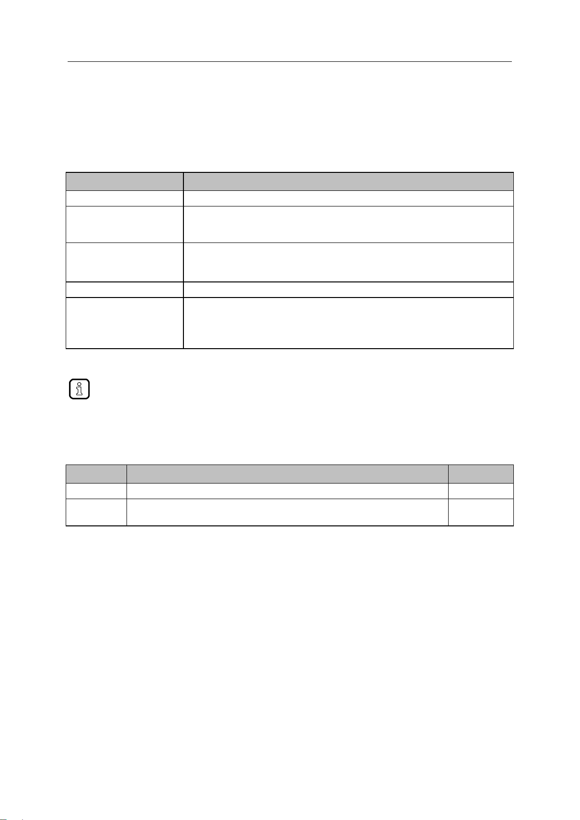
>
Document
Content / Description
Data sheet
Technical data of the device as a table
Operating instructions *
Notes on mounting and electrical installation of the device
Set-up, description of the operating and display elements, maintenance information, scale
drawing
Device manual
Notes on operation of the device via GUI and web interface
Error elimination
Description of the fieldbus data
Supplement device manual
Description of the acyclic data sets and the command interface
Programming manual
Creation of a project with the device using CODESYS
Configuration of the device using CODESYS
Programming of the SPS of the device
Description of the device-specific CODESYS function libraries
The user can download all documents from the ifm website.
Version
Topic
Date
00
New creation of document
12 / 2017
01
Update to Firmware 4.3.1
Changed: Restore device configuration
09 / 2018
1.4 Overview: User documentation for AC1403/04
41793
ifm electronic provides the following user documentation for the models of the device class "SmartSPS
DataLine mit Profinet-Device-Schnittstelle":
*... The operating instructions are supplied with the device.
>
1.5 Modification history
34492

SmartPLC DataLine with Profinet device interface
8
2 Safety instructions
Content
General safety instructions ....................................................................................................................... 8
Required background knowledge ............................................................................................................. 8
Tampering with the unit ............................................................................................................................ 8
WARNING!
Tampering with the unit.
> In case of non-compliance:
Possible affects on safety of operators and machinery
Expiration of liability and warranty
► Do not open the devices!
► Do not insert any objects into the devices!
► Prevent metal foreign bodies from penetrating!
>
28333
2.1 General safety instructions
41415
Read this document before setting up the product and keep it during the entire service life.
Only use the product for its intended purpose.
If the operating instructions or the technical data are not adhered to, personal injury and/or damage to
property may occur.
Improper or non-intended use may lead to malfunctions of the device, to unwanted effects in the
application or to a loss of the warranty claims.
The manufacturer assumes no liability for any consequences caused by tampering with the device or
incorrect use by the operator.
► Observe these operating instructions.
► Adhere to the warning notes on the product.
>
2.2 Required background knowledge
41648
This document is intended for specialists. Specialists are people who, based on their relevant training
and experience, are capable of identifying risks and avoiding potential hazards that may be caused
during operation or maintenance of the product.
For programming these people should also have knowledge of control technology experience in PLC
programming to IEC 61131-3.
The document contains information about the correct handling of the product.
>
2.3 Tampering with the unit
33190

SmartPLC DataLine with Profinet device interface
9
3 System description
Content
Intended use ...........................................................................................................................................10
Information concerning the device .........................................................................................................11
28392

SmartPLC DataLine with Profinet device interface
10
>
Content
Permitted use .........................................................................................................................................10
Prohibited use .........................................................................................................................................10
3.1 Intended use
>
36928
3.1.1 Permitted use
36762
The device is designed for operation in the control cabinet.
The device may only be used for the following purposes:
as AS-i master in 1 or 2 AS-i networks to control the data exchange to the sensor/actuator level
as gateway between the AS-i network and a higher-level controller (PROFINET-Controller = Host;
e.g. PLC) via the fieldbus interface
as Programmable Logic Controller (PLC) for program-based parameter setting, control and
regulation of the AS-i slaves connected to the device
as EtherCAT master (software extension)
as fieldbus slave (software extension)
>
3.1.2 Prohibited use
34228
The device may not be used beyond the limits of the technical data (→ Technical data (→ S. 112))!
SmartPLC DataLine with Profinet device interface
11
>
Content
Overview .................................................................................................................................................11
Operating elements ................................................................................................................................12
Display elements ....................................................................................................................................12
CODESYS SPS ......................................................................................................................................12
Interfaces ................................................................................................................................................13
Required accessories .............................................................................................................................13
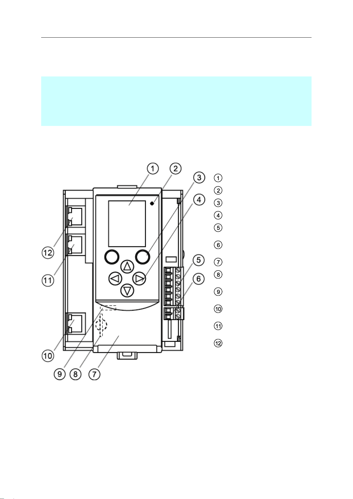
Legend:
Display
Status LED (H1)
2 function keys
4 arrow keys
Connector (X1) for
AS-i 1, AS-i 2, functional earth
Connector (X2) for AUX
(here with AUX jumper)
Front flap
Slot for SD card (behind the front
flap)
Ethernet configuration interface 1
(X3) (behind the front flap)
Ethernet configuration interface 2
(X8) with status LED (H6, H7)
PROFINET interface 2 (X7) with
status LED (H4, H5)
PROFINET interface 1 (X6) with
status LED (H2, H3)
3.2 Information concerning the device
>
3.2.1 Overview
36905
36757

SmartPLC DataLine with Profinet device interface
12
>
For information about the programming of the device-internal SPS with CODESYS, please
refer to the programming manual:
→ www.ifm.com > product page > [Downloads]
3.2.2 Operating elements
The device provides the following operating elements.
>
Arrow and function keys
Below the display is the key panel with two function keys and four arrow keys. The operator controls
the Graphical User Interface (GUI) of the device with the keys.
Operating notes: → Operation (→ S. 14)
>
3.2.3 Display elements
The device provides the following display elements:
>
Display
The display is used to display the Graphical User Interface (GUI) of the device.
Operating notes: → Operation (→ S. 14)
Technical data: → Technical data (→ S. 112)
>
36790
36959
36917
36894
Status LEDs
36784
The device features the following status LEDs which display the current status of system components.
Meaning of the LED colours and flashing frequencies: → Status LED (→ S. 105)
>
3.2.4 CODESYS SPS
36953
The device features a Programmable Logic Controller (PLC). The PLC can run the following
application types:
Applications that have been created with the IEC 61131-3 compliant programming software
"CODESYS Development System" (from version V3.5 SP9 Patch 7 Hotfix 3)
System solutions that have been provided by ifm electronic
Technical data: → Programmable Logic Controller (PLC) (→ S. 113)

SmartPLC DataLine with Profinet device interface
13
>
3.2.5 Interfaces
The device provides the following interfaces:
>
Ethernet configuration interfaces
The configuration interface 1 (X3) is behind the front flap of the device.
The configuration interface 2 (X8) is underneath the PROFINET interface (X6/X7).
The user can access the following functions via both interfaces:
web interface for device configuration and diagnostics
Programming of the device-internal SPS and the fail-safe PLC with CODESYS
Operation as additional fieldbus interface
Possible network topologies: → Configuration interfaces: Connection concepts (→ S. 115)
Technical data: → Technical data (→ S. 112)
>
PROFINET fieldbus interface
The device communicates with the higher-level control instance of the PROFINET network via the
PROFINET interface (X6/X7).
Notes regarding connetion concepts: → Configuration interfaces: Connection concepts (→ S. 115)
Technical data: → Technical data (→ S. 112)
>
36927
36913
36925
SD card slot
The SD card slot (X5) is located behind the front flap of the device. The following actions can be
performed with an SD card:
update the firmware of the device
save/restore the device configuration
Technical data: → Technical data (→ S. 112)
>
3.2.6 Required accessories
To be able to operate the device in a sensible way you need the following accessories (not supplied
with the device):
Depending on the selected voltage supply ( Operating instructions) you need:
a power supply for the 24 V power supply (e.g. art. no. DN3011)
for each AS-i master one AS-i power supply each (e.g. art. no. AC1236)
a data decoupling module AC1250 (accessory, optional)
AS-i slaves.
36761
36764

SmartPLC DataLine with Profinet device interface
14
4 Operation
Content
Control of the graphical user interface ...................................................................................................14
Menu view...............................................................................................................................................16
Page view ...............................................................................................................................................19
Remote access .......................................................................................................................................32
Legend:
Label left function key
Navigation compass
Label right function key
Right function key
Left function key
[] arrow key
[] arrow key
[] arrow key
[] arrow key
>
4.1 Control of the graphical user interface
Below the display is the key panel with six membrane keys. The operator controls the graphical user
interface of the device with these keys. The key panel is closely linked to the navigation status bar.
41713
41568
SmartPLC DataLine with Profinet device interface
15
>
The two function keys allow the operator to trigger specified
actions (e.g. tick a checkbox). The function of the function keys
changes depending on the context.
The two text fields in the navigation status bar are
associated with the function keys located directly below the
display. They indicate the action that will be triggered if the
function key is pressed in the current work step. If the function
key is not labelled, it means that it has no function in the
present situation.
Example (→ figure):
► The left function key triggers the action [Select].
► The right function key triggers the action [Back].
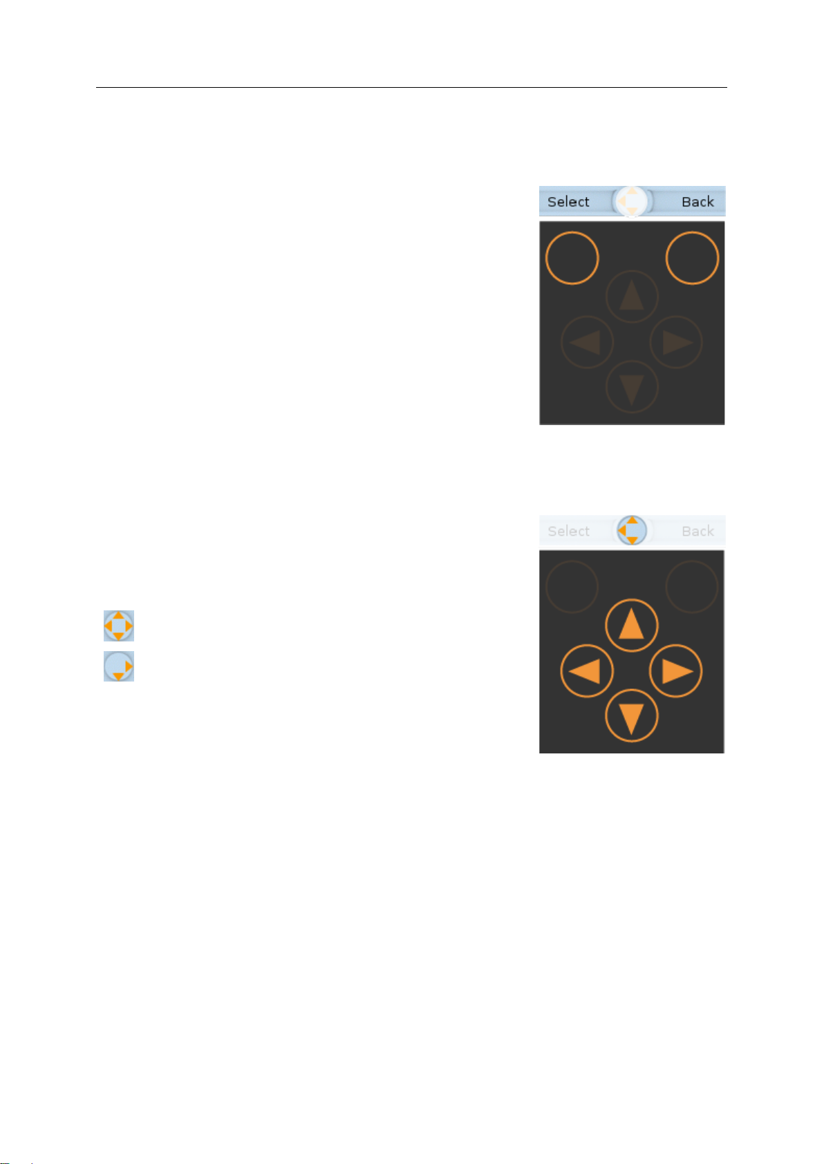
The fourarrow keys [], [], [] and [] can be used for
navigation and selection.
The navigation compass shows which of the four arrow keys
can be used in the respective work step.
Examples:
All arrow keys are active and will trigger a device
response when pressed.
Only the arrow keys [] and [] are active and will
trigger a device response when pressed.
4.1.1 Function keys
>
4.1.2 Arrow keys
41476
7091
SmartPLC DataLine with Profinet device interface
16
>
Legend:
Info bar
Main navigation bar
Subnavigation bar 1
Subnavigation bar 2
Selected menu item (focus)
Navigation status bar with
labelling of the function keys
navigation compass
Long texts are displayed as scrolling text in the info bar.
4.2 Menu view
41755
The menu view allows the user to select the menu page with the required control or display function.
>
4.2.1 Menu navigation
41756
The central operating elements in the menu view are the three navigation bars. They reflect the
menu structure of the device software. Each navigation bar represents a menu level. The symbols in a
navigation bar represent the submenus and menu items.
Rules for menu navigation:
► Use [] / [] to navigate within a menu level.
> The selected symbol has the focus (= orange frame).
> If the selected symbol has a submenu, the corresponding subnavigation bar will automatically
appear.
► Use [] to go one menu level down.
► Use [] to go one menu level up.
At th
e lowest menu level:
► Press [Select] function key to go to the page of the selected menu item (→Page view (→ S. 19)).
In the main navigation bar:
► Press [Back] function key to return to the start screen (→Start screen (→ S. 36)).

SmartPLC DataLine with Profinet device interface
17
>
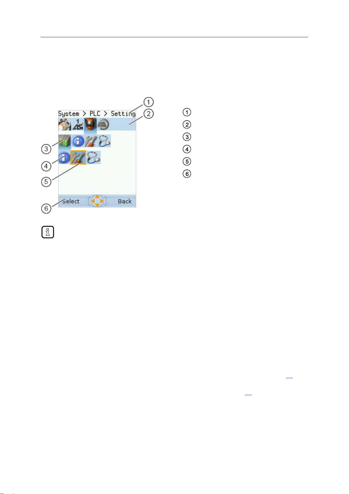
Legend:
Info bar
Navigation path to the focused menu element:
[System] > [PLC] > [Setup]
Menu element with focus
Navigation path to the focused menu element:
> >
1.
> Initial position when accessing the menu screen
2.
► Use [] to select the [System] menu symbol.
> The focus is on the [System] menu symbol.
> The first subnavigation bar appears.
3.
► Use [] to change to the first subnavigation barh.
> The focus is on the [Diagnosis] menu symbol.
4.
► Use [] to select the [PLC] menu symbol.
> The focus is on the [PLC] menu symbol.
> The second subnavigation bar appears.
5.
► Use [] to change to the second subnavigation bar.
> The focus is on the [Information] menu symbol.
4.2.2 Navigation aids
The following screen elements help you navigate through the menu:
> The info bar shows the navigation path of the selected menu symbol.
> The navigation compass shows which navigation steps are possible from the current position.
>
Example
To access the menu page containing the setting options for the device-internal PLC:
41748
41499

SmartPLC DataLine with Profinet device interface
18
6.
► Use [] to select the [Settings] menu symbol.
> The focus is on the [Settings] menu symbol.
► Press the [Select] function key to go to the page view
of the [Settings] menu item.
> The page shows the setting options for the
device-internal PLC.
SmartPLC DataLine with Profinet device interface
19
>
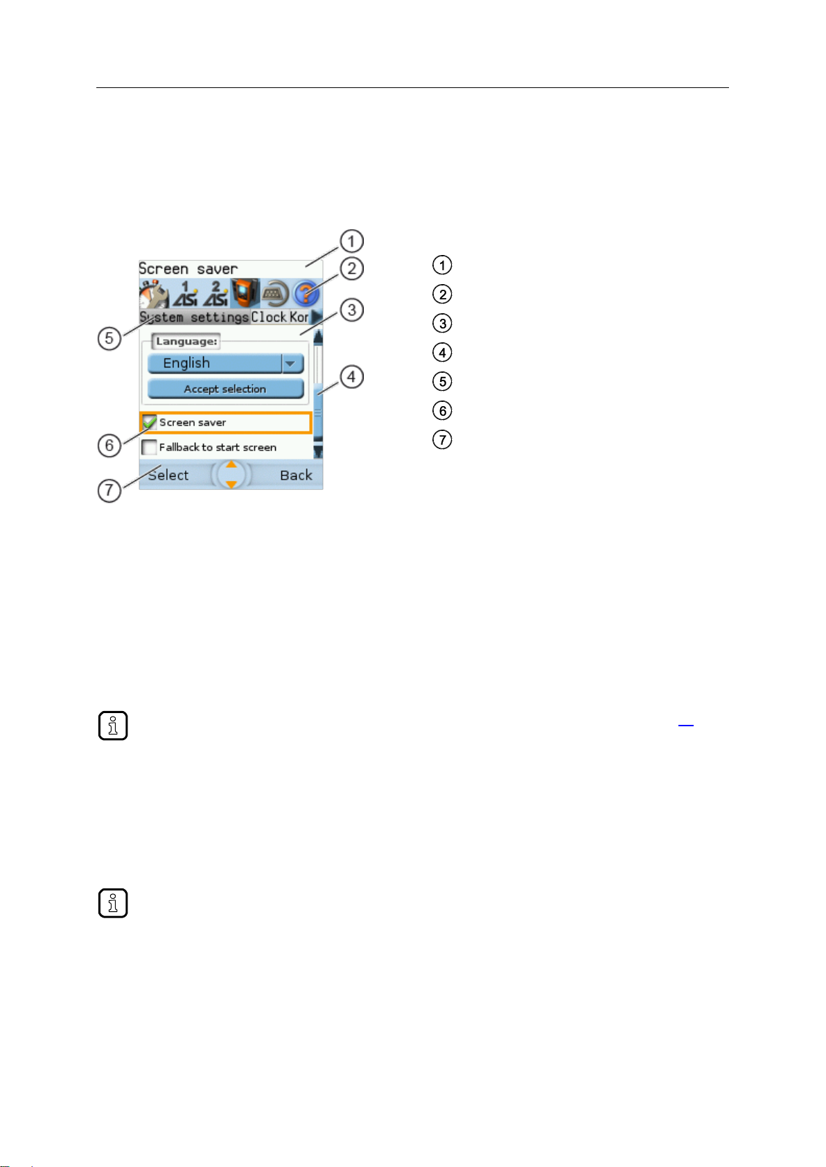
Legend:
Info bar
Main navigation bar
Page
Scroll bar
Tab menu
Page element with focus
Navigation status bar with
labelling of function keys
navigation compass
Rules for using the different control elements: →Description of the control elements (→ S. 20)
Long texts are displayed as scrolling text in the info bar.
4.3 Page view
The page view allows the user to select and execute a requested function.
>
41786
4.3.1 Navigate on a page
The page contains elements, that allow the operator to control the device or access information.
For page navigation, the following basic rules apply:
► Use the arrow keys [] / [] to change between the different page elements.
> The selected element is marked (= orange frame).
► Use the [Back] function key to return to the tab menu / menu view.
>
4.3.2 Use navigation aids
The following aids offer navigation users additional orientation:
> The info bar shows detailed information about the selected element (focus).
> The active menu symbol in the main navigation bar has a dark background.
> A scroll bar appears on the right side of the screen if the elements do not fit on the page.
> The navigation compass shows the navigation options in the active work step.
> The text fields in the navigation status bar show the current assignment of the function keys.
41749
41678

SmartPLC DataLine with Profinet device interface
20
>
Content
Tab menu/Tab ........................................................................................................................................21
Button .....................................................................................................................................................22
Checkbox ................................................................................................................................................22
List ..........................................................................................................................................................23
Slave selector .........................................................................................................................................24
Confirmation message ............................................................................................................................29
Numerical field ........................................................................................................................................30
Binary field ..............................................................................................................................................31
4.3.3 Description of the control elements
A page consists of different control elements.
41586

SmartPLC DataLine with Profinet device interface
21
>
> The focused tab has an orange background
> The info bar displays the name of the active tab (in this
example: Errors / slave).
> The symbols and indicate that there are more tabs on
the left and right sides of the visible tab.
> The page shows the control elements that belong to the
currently selected tab.
=
Tab has the focus
=
Tab is active
=
Tab is inactive
Tab menu/Tab
A tab menu groups together the different functions of a menu page. A tab menu consists of at least
two tabs. A tab combines related functions.
Example:
Tabs can have the following background colours:
Use:
1 Select the menu item
► Go to the menu item with the tab menu.
> The tab menu appears.
> The focus is on the left-hand tab.
2 Select a tab
► Use [] / [] arrow key to select the desired tab.
> The focus (orange background) moves to the selected tab:
> The page shows the functions of the selected tab.
3 Activate the menu page
► Press [Select] arrow key to go to the page that belongs to the active tab.
> When going to the page, the tab menu remains visible.
> The background colour of the active tab turns grey.
4 Carry out the desired functions
► Use [] to select and execute the desired function.
5 Change to tab menu
► Press [Back] function key to change to the tab menu.
> The focus (orange background) moves to the active tab.
41675

SmartPLC DataLine with Profinet device interface
22
>
The setting or clearing of a checkbox is not always immediately effective. Often the change
must be confirmed by clicking a button (e.g. [Accept selection])!
Button
41536
A button allows the operator to carry out a specified action once. The caption on the button describes
the action.
Example:
Use:
1 Select a button
► Use the arrow keys [] / [] to select a button.
> The selected button gets an orange frame:
2 Activate the button
► Use [Select] function key to activate the selected button.
> The function is executed.
>
Checkbox
41600
A checkbox permits the user to activate/deactivate a parameter. A checkbox control element consists
of a checkbox and a caption.
Example:
Use:
1 Select a checkbox
► Use [] / [] arrow key to select the checkbox
> The focus (orange frame) moves to the selected checkbox
OR:
2 Check/uncheck a checkbox
► Use [Select] function key to check/uncheck the selected checkbox.
> The status change is indicated:
= checkbox is checked
OR:
= checkbox is unchecked
SmartPLC DataLine with Profinet device interface
23
>
= list without caption
= list with caption
The set value will not always become effective immediately. Often the change must be
confirmed by clicking a button (e.g. [Accept selection])!
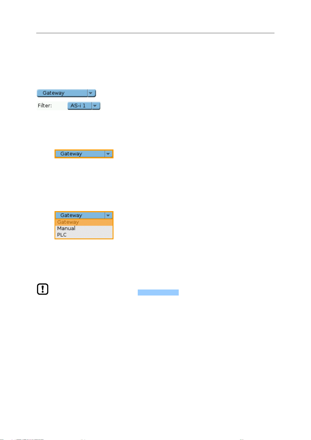
List
41484
A list provides a set of defined values. The operator can select precisely one value from this set (= 1 of
n selection).
Examples:
Use:
1 Select a list
► Use [] / [] arrow key to select the list.
> The focus (orange frame) moves to the selected list.
> The list shows the active value: (in this exampleGateway).
2 Activate the list
► Use [Select] function key to open the list.
> The opened list shows the selectable values.
3 Select a value
► Use [] / [] arrow key to select the desired value from the list.
> The background colour of the selected value turns orange.
4 Apply the selected value
► Use [Select] function key to apply the selected value.
OR:
Use [Back] function key to quit and close the list.
> The list shows the selected value.
SmartPLC DataLine with Profinet device interface
24
>
Content
Overview of slave states .........................................................................................................................25
Overview of free slave addresses ..........................................................................................................27
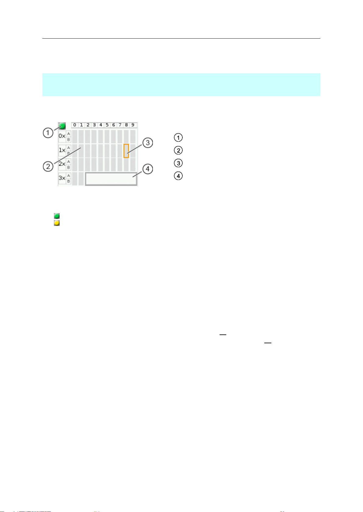
Legend:
Indicator of AS-i master operating mode
AS-i address symbol
Highlighted AS-i address (focus)
Status message of highlighted AS-i address
Slave selector
The slave selector is used to select an AS-i slave or an AS-i address.
> The status LED indicates the active operating mode of the AS-i master:
= AS-i master in protected mode
= AS-i master in projection mode
> Every field represents an AS-i address. An AS-i address can be occupied by:
– a single slave symbol
– an A/B slave pair symbol
> The row and column headers help to locate the AS-i address.
Example: address of the field selected in the picture
– row header: 1x (= tens digit of the AS-i address)
– column header: 8 (= units digit of the AS-i address)
– type of slave: single slave (= symbol fully occupies the address field)
– resulting AS-i address: 18
> The symbol of the A/B slave pair appears when an A or B slave is used on this address.
The slave selector is used in the following overviews:
Overview of slave states (→ Overview of slave states (→ S. 25))
Overview of free slave addresses (→ Overview of free slave addresses (→ S. 27))
41653

SmartPLC DataLine with Profinet device interface
25
>
> The slave selector shows an overview of the slaves in the
selected AS-i network.
> The symbol colour signals the slave status. Meaning of
symbols and colours:
→ Slave status: colour code + symbols (→ S. 26)
> The text field displays the status of the selected AS-i slave.
Possible status messages:
Slave active
Not projected (= configuration error)
Double address (= double address error)
Periphery (= periphery fault)
Overview of slave states
Use:
1 Select an AS-i slave
► Use the arrow keys [], [], [] and [] to select the desired AS-i slave.
> The focus (= orange frame) is on the selected AS-i slave.
> The info bar shows the address of the selected AS-i slave.
> The text field shows a status message about the selected AS-i slave.
2 Activate the selected AS-i slave
► Use [Select] function key to activate the selected AS-i slave and go to the next menu page.
OR:
Use [Back] function key to cancel and leave the slave selector.
41728
SmartPLC DataLine with Profinet device interface
26
>
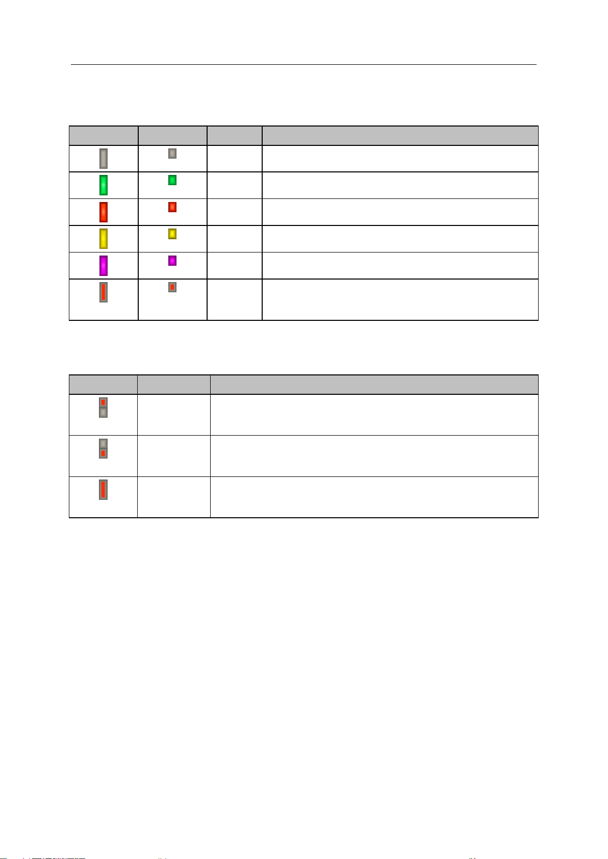
Single slave
A/B slave
Colour
Meaning
grey
No slave found:
slave address is neither in the LPS nor in the LDS
green
Slave is activated ( in LAS)
red
Configuration error type 1:
slave is projected (in LPS) but was not found (in LDS)
yellow
Slave signals a peripheral fault
pink
Several slaves have the same address (double address error)
grey red
Configuration error type 2:
the found slave (in LDS) is not projected (in LPS)
the found slave has another profile than projected
Symbol
Colour
Meaning
grey red
grey
Configuration error type 2:
Single slave is projected (in LPS) but was not found (in LDS).
Instead, a new A slave with the same address was installed.
grey
grey red
Configuration error type 2:
Single slave is projected (in LPS) but was not found (in LDS).
Instead, a new B slave with the same address was installed.
grey red
Configuration error type 2:
A or B slave is projected (in LPS) but was not found (in LDS).
Instead, a new single slave with the same address was installed.
Slave status: colour code + symbols
>
Meaning of the colour combinations (example: configuration error type 2)
41652
41741

SmartPLC DataLine with Profinet device interface
27
>
> The symbol colour indicates the state of the AS-i address.
Meaning of symbols and colours:
→ Free slave addresses: colour code + symbols (→ S. 28)
> The text field displays the status of the selected AS-i slave.
Possible status messages:
Free
Missing slave
Overview of free slave addresses
In this overview, the slave selector shows the free and occupied AS-i addresses.
Use:
1 Select the AS-i address
► Use the arrow keys [], [], [] and [] to select the desired AS-i address.
> The focus (= orange frame) is on the selected AS-i address.
> The info bar displays the selected AS-i address.
> The text field shows a status message for the selected AS-i address.
2 Activate the selected AS-i address
► Press [Select] function key to activate the selected AS-i address and go to the next menu page.
OR:
Press [Back] function key to cancel and leave the slave selector.
41729
SmartPLC DataLine with Profinet device interface
28
>
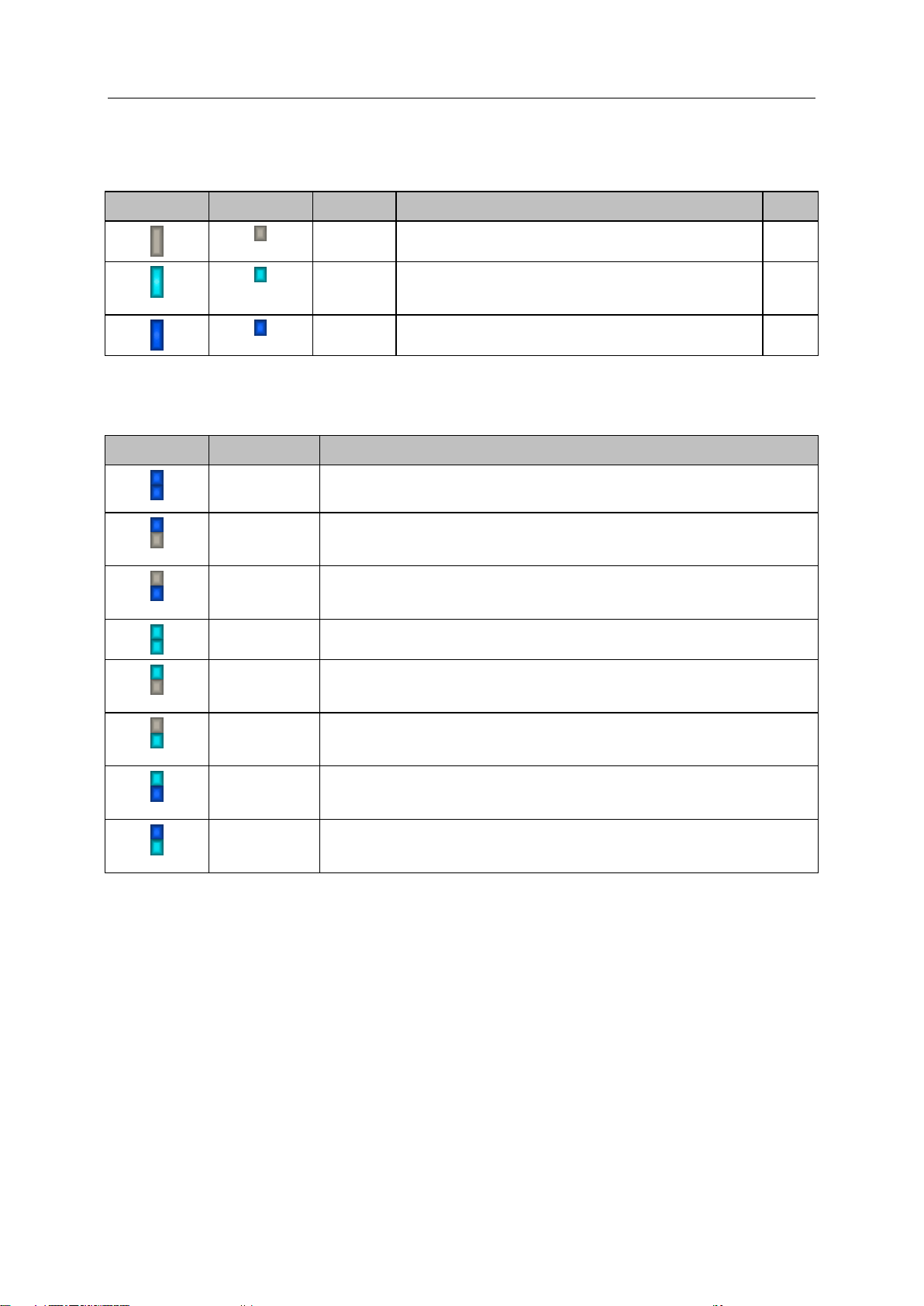
Single slave
A/B slave
Colour
Meaning
Prio.
grey
Slave address is already used.
--
turquoise
Address is free according to LDS (= no slave found), however:
address already belongs to a stored projection (= application
profile).
1
blue
Address is free according to LDS (= no slave found).
Address is not used in a stored projection (= application profile).
2
Symbol
Colour
Meaning
blue
blue
Slave to be addressed is an A/B slave:
A and B addresses are free.
blue
grey
Slave to be addressed is an A/B slave:
– A address is free.
– B address is used.
grey
blue
Slave to be addressed is an A/B slave:
– A address is used.
– B address is free.
turquoise
turquoise
Slave to be addressed is an A/B slave:
A and B addresses are free, but already used in a stored projection.
turquoise
grey
Slave to be addressed is an A/B slave:
– A address is free, but already used in a stored projection.
– B address is used.
grey
turquoise
Slave to be addressed is an A/B slave:
– A address is used.
– B address is free, but already used in a stored projection.
turquoise
blue
Slave to be addressed is an A/B slave:
– A address is free, but already used in a stored projection.
– B address is free.
blue
turquoise
Slave to be addressed is an A/B slave:
– A address is free
– B address is free, but already used in a stored projection.
Free slave addresses: colour code + symbols
>
Meaning of the colour combinations
41493
41736
SmartPLC DataLine with Profinet device interface
29
>
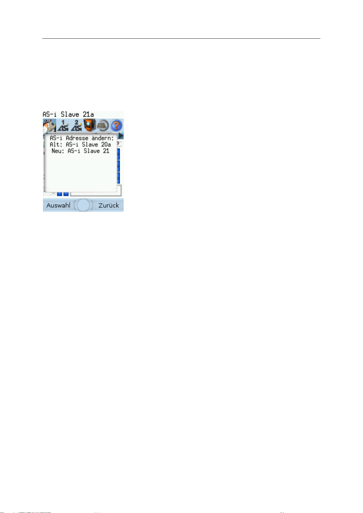
> Action: Change AS-i slave address from 1a to 1b
> Confirmation message shows:
Action (= Change AS-i address)
Slave address prior to change
Slave address after change
> The operator has the following input options:
[Select] function key
[Back] function key
Confirmation message
The confirmation message is a security prompt. It appears when important changes are made to the
system settings. The confirmation message shows the changes made. For the changes to become
effective, they first need to be acknowledged by the operator.
Example:
Use:
1 Change the settings
► Change the system settings.
> The confirmation message appears.
2 Confirm the message
► Press [Select] function key to confirm the changes and apply the new value.
OR:
Press [Back] function key to reject the changes and continue to use the old value.
> The page displays the valid settings.
41606
SmartPLC DataLine with Profinet device interface
30
>
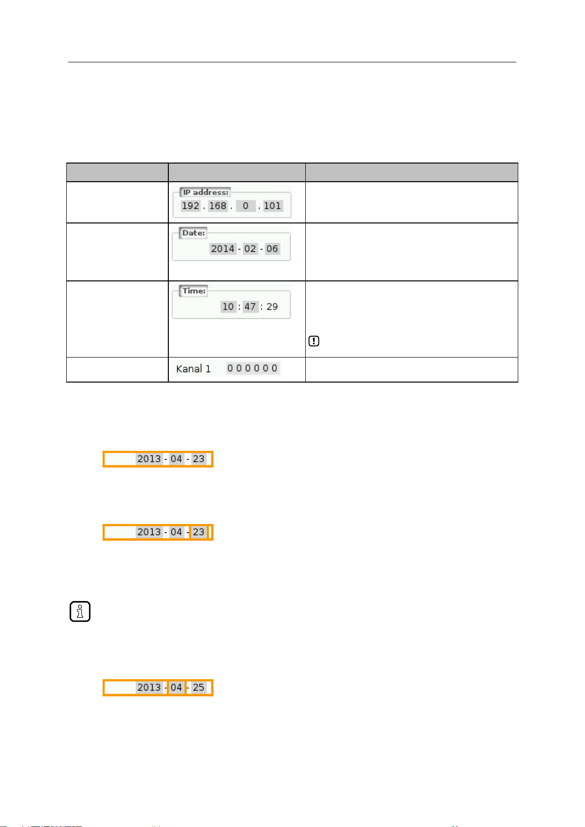
Control element
Example
Meaning
IP address
Entry of an IP address (IPv4) in [w.x.y.z] format
w | x | y | z = network segments (value range: 0... 255)
Date Date entry in [yyyy-mm-ss] format
yyyy = year (value range: 0000 ... 9999)
mm = month (value range: 01 ... 12)
dd = day (value range: 01 ... 31)
Time
Time entry in [hh:mm:ss] format
hh = hours (value range: 00 ... 12)
mm = minutes (value range: 00 .... 59)
ss = seconds (value range: 00 ... 59)
The numerical field for seconds (ss) cannot be
edited!
Analogue value
Entry of an analogue output value
Value range (per numerical field): 0 ... 9
Press and hold the arrow key [] / [] to rapidly move through larger value ranges.
Numerical field
The numerical field allows the operator to enter integer values. The value range is context-specific.
Numerical fields are part of the following GUI elements:
41720
Use (using the example of the numerical date field):
1 Select a numerical field
► Use [] / [] arrow key to select the date control element.
> The focus (= orange frame) is on the selected date control element.
> The date control element displays the current date
2 Activate the editing mode
► Press [Select] function key to enter the editing mode.
> The focus (orange frame) is on the right element
3 Set the desired value
► Use [] / [] arrow key to increment the desired value.
> The segment displays the new value.
4 Select the next segment
► Use the arrow key [] / [] to mark the segment to be edited.
> The focus (orange frame) moves to the marked segment
► Optional: Repeat steps 3 and 4 until all segments have the desired values.
 Loading...