

Page 1

Supplementary device manual
AS-i controllere with Profibus DPV1
A
AC1355, AC1356
AC1365, AC1366
AS-i master profile: M4
Firmware: from version RTS 3.0 onwards
Target: from V.15 onwards
®
for CoDeSys
from version 2.3 onwards
7390702 / 01 08 / 2008
1
Page 2

2
As on: 14 Aug. 2008
© All rights reserved by ifm electronic gmbh.
No part of this manual may be reproduced and used
without ifm electronic's consent.
Page 3

Contents
1
On this manual .........................................................................................................................1-1
1.1 What do the symbols and formats stand for?................................................................ 1-1
1.2 What devices are described in this manual?................................................................. 1-2
1.3 How is this manual structured? ..................................................................................... 1-2
1.4 Overview: where is what? ............................................................................................. 1-3
2 Safety instructions................................................................................................................... 2-1
2.1 General.......................................................................................................................... 2-1
2.2 What previous knowledge is required? ......................................................................... 2-1
2.3 Functions and features.................................................................................................. 2-1
3 System requirements............................................................................................................... 3-1
3.1 Information concerning the device ................................................................................ 3-1
3.2 Information concerning the software ............................................................................. 3-1
3.3 Required accessories.................................................................................................... 3-1
4 Getting started.......................................................................................................................... 4-1
4.1 Connection .................................................................................................................... 4-1
4.2 Set up the AS-i master .................................................................................................. 4-1
4.3 Set up Profibus DPV1 ................................................................................................... 4-1
5 Function.................................................................................................................................... 5-1
5.1 Data management......................................................................................................... 5-1
5.2 Status LED for the fieldbus............................................................................................ 5-2
5.3 Which operating modes are there for the PLC in the controllere? ................................ 5-2
6 Menu..........................................................................................................................................6-1
6.1 Main menu [Quick Setup] .............................................................................................. 6-1
6.2 Main menu [Fieldbus Setup].......................................................................................... 6-2
7 Set-up ........................................................................................................................................ 7-1
7.1 Parameter setting of the controllere.............................................................................. 7-1
7.1.1 Parameter setting of slaves in the controllere.................................................. 7-1
7.1.2 Set the parameters of the fieldbus interface in the controllere......................... 7-1
7.2 Connect the controllere to the Profibus host ................................................................. 7-2
7.3 Parameter setting of the Profibus host.......................................................................... 7-2
7.3.1 Assigning the addresses of the inputs/outputs to the host "locations"............. 7-4
7.3.2 Assign PLC addresses to the Profibus modules ............................................ 7-11
7.3.3 Define Profibus DP modules .......................................................................... 7-13
3
Page 4

Device-specific Profibus DP parameters..................................................................... 7-25
7.4
7.4.1 Device-specific Profibus DP parameters (example)....................................... 7-25
7.4.2 Definitions in the GSD file............................................................................... 7-26
7.5 Finish set-up ................................................................................................................ 7-27
8 DP module 7: Command channel........................................................................................... 8-1
8.1 List of commands in module 7....................................................................................... 8-1
8.2 Module 7, command 1: read master flags.................................................................... 8-2
8.3 Module 7, command 2: change operating mode.......................................................... 8-3
8.4 Module 7, command 3: read current slave configuration ............................................. 8-4
8.5 Module 7, command 4: read projected slave configuration ......................................... 8-5
8.6 Module 7, command 5: change projected slave configuration..................................... 8-6
8.7 Module 7, command 6: read slave parameter.............................................................. 8-7
8.8 Module 7, command 7: change projected slave parameters ....................................... 8-8
8.9 Module 7, command 8: read LAS (list of active slaves) ............................................... 8-9
8.10 Module 7, command 9: read LDS (list of detected slaves) ........................................ 8-11
8.11 Module 7, command 10
8.12 Module 7, command 11
8.13 Module 7, command 13
8.14 Module 7, command 14
8.15 Module 7, command 15
8.16 Module 7, command 16
8.17 Module 7, command 19
8.18 Module 7, command 21
8.19 Module 7, command 22
8.20 Module 7, command 23
8.21 Module 7, command 62
8.22 Module 7, command 63
dec
dec
dec
dec
dec
dec
dec
dec
dec
dec
dec
dec
(0A
): read LPF (list of slaves with periphery fault)....... 8-12
hex
(0B
): read LPS (list of projected slaves) ...................... 8-13
hex
(0D
): read telegram error counter ................................ 8-14
hex
(0E
): read configuration error counter.......................... 8-15
hex
(0F
): read AS-i cycle counter ....................................... 8-16
hex
(10
): change current slave parameters........................ 8-17
hex
(13
): config. all ............................................................. 8-18
hex
(15
): save configuration in flash ................................... 8-19
hex
(16
): reset telegram error counter of a slave ............... 8-20
hex
(17
): address slave ...................................................... 8-21
hex
(3E
): operating mode "continuous command“ ............. 8-22
hex
(3F
): no operation command without function ............. 8-23
hex
9 DP module 12: Extended command channel ........................................................................ 9-1
9.1 List of extended commands in module 12..................................................................... 9-1
9.2 Data structure ................................................................................................................ 9-3
9.3 Error codes in the module 12 ........................................................................................ 9-5
9.4 CTT2 error code in module 12 ...................................................................................... 9-5
9.5 Module 12, extended command 0: no execution of a command ................................. 9-6
9.6 Module 12, extended command 1: write parameters to a connected AS-i slave......... 9-7
9.7 Module 12, extended command 3: adopt and store connected AS-i slaves in the
configuration ..................................................................................................................
9.8 Module 12, extended command 4: write LPS ............................................................ 9-11
9.9 Module 12, extended command 5: set the operating mode of the AS-i master......... 9-13
9.10 Module 12, extended command 6: readdress a connected AS-i slave...................... 9-15
9.11 Module 12, extended command 7: set the auto address mode of the AS-i master... 9-17
9.12 Module 12, extended command 9: change extended ID code 1 in the AS-i slave .... 9-18
4
9-9
Page 5

Module 12, extended command 10...20
9.13
directly to / from 3 AS-i slaves in each case ...............................................................
(0A...14
dec
): force analogue data transfer
hex
9-20
9.14 Module 12, extended command 21
AS-i slave with the profile 7.4 ......................................................................................
9.15 Module 12, extended command 26
9.16 Module 12, extended command 28
changing to the protected mode..................................................................................
9.17 Module 12, extended command 31
"Extended safety monitor protocol" in the "Safety at work" monitor............................
9.18 Module 12, extended command 33
of an AS-i slave with the profile S-7.4 .........................................................................
9.19 Module 12, extended command 34
of an AS-i slave with the profile S-7.4 .........................................................................
9.20 Module 12, extended command 35
of an AS-i slave with the profile S-7.4 .........................................................................
9.21 Module 12, acyclic command 36
dec
with CTT2 profile (S-7.5.5, S-7.A.5 or S-B.A.5) .........................................................
9.22 Module 12, acyclic command 37
dec
with CTT2 profile (S-7.5.5, S-7.A.5 or S-B.A.5) .........................................................
9.23 Module 12, acyclic command 38
dec
of an AS-i slave with CTT2 profile (S-7.5.5, S-7.A.5 or S-B.A.5) ...............................
9.24 Module 12, acyclic command 39
dec
of an AS-i slave with CTT2 profile (S-7.5.5, S-7.A.5 or S-B.A.5) ...............................
(15
dec
dec
dec
dec
dec
dec
dec
(24
(25
(26
(27
): read ID character string of an
hex
(1A
): read AS-i master version................... 9-28
hex
(1C
): deactivate the slave reset when
hex
(1F
): one-time execution of the
hex
(21
): read the diagnostic character string
hex
(22
): read parameter character string
hex
(23
): write parameter character string
hex
): standard read call of an AS-i slave
hex
): standard write call of an AS-i slave
hex
): manufacturer-specific read call
hex
): manufacturer-specific write call
hex
9-25
9-29
9-30
9-35
9-37
9-38
9-40
9-44
9-47
9-51
9.25 Module 12, extended command 50
of AS-i slaves 0(A)...15(A)...........................................................................................
9.26 Module 12, extended command 51
of AS-i slaves 16(A)...31(A).........................................................................................
9.27 Module 12, extended command 52
of the AS-i slaves 1B...15B..........................................................................................
9.28 Module 12, extended command 53
of the AS-i slaves 16B...31B........................................................................................
9.29 Module 12, extended command 54
connected AS-i slaves.................................................................................................
9.30 Module 12, extended command 55
9.31 Module 12, extended command 56
of the AS-i slaves 0(A)...15(A).....................................................................................
9.32 Module 12, extended command 57
of the AS-i slaves 16(A)...31(A)...................................................................................
9.33 Module 12, extended command 58
of the AS-i slaves 1B...15B..........................................................................................
9.34 Module 12, extended command 59
of the AS-i slaves 16B...31B........................................................................................
9.35 Module 12, extended command 96
flash memory of the controllere...................................................................................
dec
dec
dec
dec
dec
dec
dec
dec
dec
dec
dec
(32
): read current configuration
hex
(33
): read current configuration
hex
(34
): read current configuration
hex
(35
): read current configuration
hex
(36
): read current parameters of the
hex
(37
): read current AS-i slave lists............... 9-61
hex
(38
): read projected configuration
hex
(39
): read projected configuration
hex
(3A
): read projected configuration
hex
(3B
): read projected configuration
hex
(60
): save data non-volatilely in the
hex
9-55
9-56
9-57
9-58
9-59
9-63
9-64
9-65
9-66
9-67
9.36 Module 12, extended command 97
controllere....................................................................................................................
9.37 Module 12, extended command 102
controllere display........................................................................................................
9.38 Module 12, extended command 105
of the controllere..........................................................................................................
dec
dec
dec
(61
): carry out various settings in the
hex
(66
): retrieve the status of the
hex
(69
): read the device properties
hex
9-68
9-69
9-71
5
Page 6

Acyclic services for Profibus DPV1 ..................................................................................... 10-1
10
10.1 Description................................................................................................................... 10-1
10.2 Services for acyclic data transfer between DPM1 master and slave.......................... 10-2
10.3 Services for acyclic data transfer between DPM2 master and slave.......................... 10-2
10.4 DPV1 addresses in slot 0 for access via PLC............................................................. 10-3
10.5 Examples..................................................................................................................... 10-5
10.5.1 Examples DPV1 reading ................................................................................ 10-5
10.5.2 Examples DPV1 writing .................................................................................. 10-5
10.6 DPV1 error messages ................................................................................................. 10-5
10.6.1 DPV1 error code application........................................................................... 10-5
10.6.2 DPV1 error codes data access....................................................................... 10-5
10.6.3 DPV1 error codes device................................................................................ 10-6
10.6.4 DPV1 error codes application-specific ........................................................... 10-6
10.6.5 DPV1 function 58 "Reason codes" ................................................................. 10-6
11 The DPV1 command channel................................................................................................11-1
11.1 Overview of the commands in the DPV1 command channel...................................... 11-1
11.2 Syntax.......................................................................................................................... 11-2
11.3 DPV1 command 0
11.4 DPV1 command 1
11.5 DPV1 command 3
dec
dec
dec
(00
(01
(03
in the configuration ......................................................................................................
11.6 DPV1 command 4
11.7 DPV1 command 5
11.8 DPV1 command 6
11.9 DPV1 command 7
11.10 DPV1 command 9
dec
dec
dec
dec
dec
(04
(05
(06
(07
(09
AS-i slave ..................................................................................................................
11.11 DPV1 command 10...20
to / from 3 AS-i slaves in each case ..........................................................................
11.12 DPV1 command 21
dec
(15
profile S-7.4 ...............................................................................................................
11.13 DPV1 command 28
dec
(1C
protected mode..........................................................................................................
11.14 DPV1 command 31
dec
(1F
protocol" in the "Safety at Work" monitor ..................................................................
11.15 DPV1 command 33
dec
(21
the profile S-7.4 .........................................................................................................
): no execution of a command.......................................... 11-4
hex
): write parameters to a connected AS-i slave ................. 11-5
hex
): adopt and store currently connected AS-i slaves
hex
): change the list of projected AS-i slaves (LPS)............. 11-9
hex
): set the operating mode of the AS-i master ................ 11-11
hex
): readdress a connected AS-i slave ............................. 11-13
hex
): set the auto address mode of the AS-i master .......... 11-15
hex
): change the extended ID code 1 in the connected
hex
(0A...14
dec
): read ID string of an AS-i slave with the
hex
): deactivate the slave reset when changing to the
hex
): one-time execution of the "Extended safety monitor
hex
): read diagnosis string of an AS-i slave with
hex
): force analogue data transfer directly
hex
11-7
11-16
11-18
11-23
11-26
11-27
11-32
11.16 DPV1 command 34
the profile S-7.4 .........................................................................................................
11.17 DPV1 command 35
the profile S-7.4 .........................................................................................................
11.18 DPV1 command 36
CTT2 profile (S-7.5.5, S-7.A.5 or S-B.A.5)...............................................................
11.19 DPV1 command 37
CTT2 profile (S-7.5.5, S-7.A.5 or S-B.A.5)...............................................................
6
dec
dec
dec
dec
(22
): read the parameter string of an AS-i slave with
hex
(23
): write parameter string of an AS-i slave with
hex
(24
): acyclic standard read call of an AS-i slave with
hex
(25
): acyclic standard write call of an AS-i slave with
hex
11-34
11-36
11-38
11-42
Page 7

DPV1 command 38
11.20
of an AS-i slave with CTT2 profile (S-7.5.5, S-7.A.5 or S-B.A.5) ..............................
dec
(26
): acyclic manufacturer-specific read call
hex
11-45
11.21 DPV1 command 39
of an AS-i slave with CTTS profile (S-7.5.5, S-7.A.5 or S-B.A.5)..............................
11.22 DPV1 command 50
AS-i slaves 0(A)...15(A).............................................................................................
11.23 DPV1 command 51
AS-i slaves 16(A)...31(A)...........................................................................................
11.24 DPV1 command 52
AS-i slaves 1B...15B..................................................................................................
11.25 DPV1 command 53
AS-i slaves 16B...31B................................................................................................
11.26 DPV1 command 54
a connected AS-i slave..............................................................................................
11.27 DPV1 command 55
11.28 DPV1 command 56
the AS-i slaves 1(A)...15(A).......................................................................................
11.29 DPV1 command 57
the AS-i slaves 16(A)...31(A).....................................................................................
11.30 DPV1 command 58
the AS-i slaves 1B…15B ...........................................................................................
11.31 DPV1 command 59
the AS-i slaves 16B…31B .........................................................................................
dec
dec
dec
dec
dec
dec
dec
dec
dec
dec
dec
(27
): acyclic manufacturer-specific write call
hex
(32
): read current configuration of
hex
(33
): Read current configuration of
hex
(34
): read current configuration of
hex
(35
): read current configuration of
hex
(36
): read current parameters of
hex
(37
): read current AS-i slave lists ..................................... 11-59
hex
(38
): projected configuration of
hex
(39
): read projected configuration of
hex
(3A
): read projected configuration of
hex
(3B
): read projected configuration of
hex
11-49
11-53
11-54
11-55
11-56
11-57
11-61
11-62
11-63
11-64
11.32 DPV1 command 96
of the controllere........................................................................................................
11.33 DPV1 command 97
11.34 DPV1 command 102
11.35 DPV1 command 105
dec
dec
dec
dec
(60
): save data non-volatilely in the flash memory
hex
(61
): carry out various settings in the controller
hex
(66
): retrieve the status of the controller
hex
(69
): read the device properties of the controller
hex
11-65
............. 11-66
e
display .......... 11-67
e
......... 11-69
e
12 Additional functions...............................................................................................................12-1
12.1 AS-i diagnosis via Profibus DP.................................................................................... 12-1
12.1.1 Digital inputs ................................................................................................... 12-1
12.1.2 Digital outputs................................................................................................. 12-1
12.1.3 Extended device-specific Profibus DP diagnosis ........................................... 12-2
12.1.4 Diagnostic master flags (byte 10 / byte 36) .................................................... 12-3
12.2 Set the Profibus DP address on the controllere.......................................................... 12-4
12.3 Read fieldbus parameters ........................................................................................... 12-6
12.4 Store system parameters .......................................................................................... 12-10
13 Technical data ........................................................................................................................ 13-1
13.1 Basic functions ............................................................................................................ 13-1
13.2 Profibus DP interface .................................................................................................. 13-1
14 Troubleshooting..................................................................................................................... 14-1
14.1 List of errors................................................................................................................. 14-1
14.2 Hardware error, exception error .................................................................................. 14-2
7
Page 8

Terms, abbreviations.............................................................................................................15-1
15
16 Index........................................................................................................................................16-1
8
Page 9
On this manual
What do the symbols and formats stand for?
1 On this manual
In this chapter you will find an overview of the following points:
• What do the symbols and formats stand for?
• What devices are described in this manual?
• How is this manual structured?
1.1 What do the symbols and formats stand for?
The following symbols or pictograms depict different kinds of remarks in this manual:
DANGER
Death or serious irreversible injuries are to be expected.
WARNING
Death or serious irreversible injuries may result.
CAUTION
Slight reversible injuries may result.
NOTICE
Property damage is to be expected or possible.
NOTE
The "i" in the square gives important information to help you handle the product or this manual
correctly.
► … Request for action
> … Reaction of device or software
→ ...
stands for "see"
abc Cross-reference (Link)
[…] [Designation] of key, signalling lamp, button, menu item ....
For several menu items to be selected consecutively we write:
[1st step] > [2nd step] > [3rd step]
ABC DESIGNATION of parameters (inputs, outputs, flags, function blocks)
Abc
● LED lit
○ LED off
✶
1-1
Designation of files and directories are written in monospace font
LED flashes
Page 10

On this manual
What devices are described in this manual?
1.2 What devices are described in this manual?
This manual describes the AS-i device family controller
of ifm electronic gmbh.
e
• with AS-i master profile M4
• with AS-i version 3.0 masters
• with a firmware from version RTS 2.2 onwards
• with the target from V.15 onwards.
In the "programming manual CoDeSys
®
2.3" more information about the use of the programming
system "CoDeSys for Automation Alliance" is given. This manual can be downloaded free of charge
from ifm's website at:
www.ifm.com> Select country/language > [Service] > [Download] > [Bus system AS-interface]
→
Description of the Ethernet programming interface
→ Separate supplement to this device manual.
1.3 How is this manual structured?
This manual is a combination of different instruction types. It is for beginners and also a reference for
advanced users.
How to use this manual:
• To find a certain subject straight away, please use the table of contents at the beginning of this
manual.
• Using the table of keywords at the end of the manual you can quickly find the term you are
looking for.
• At the beginning of a chapter we will give you a brief overview of its contents.
• You can find the title of the current chapter in bold in the header of each page. Below is the
current title of the second order.
• You can find the chapter-related number of the page in the footer of each page.
Abbreviations and technical terms
→ Chapter
Terms, abbreviations at the end of the manual.
We reserve the right to make alterations which can result in a change of contents of the manual. You
can find the current version on ifm's website at:
www.ifm.com > Select country/language > [Service] > [Download] > [Bus system AS-interface]
→
Nobody is perfect. Send us your suggestions for improvements to this manual and you will receive a
little gift from us to thank you.
© All rights reserved by ifm electronic gmbh. No part of this manual may be reproduced and used
without ifm electronic's consent.
1-2
Page 11
On this manual
Overview: where is what?
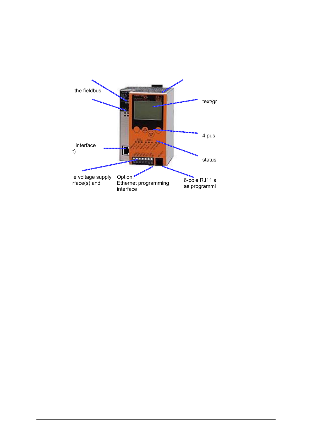
1.4 Overview: where is what?
metal housing IP20 key to unlock the device from a rail
status LEDs of the fieldbus
interface
(option)
text/graphics display
4 pushbuttons
option: fieldbus interface
(here: Ethernet)
terminals for the voltage supply
24 V, AS-i interface(s) and
protective wire
Figure: overview controllere
Option:
Ethernet programming
interface
status LEDs
6-pole RJ11 socket of RS-232C
as programming interface
1-3
Page 12

On this manual
Overview: where is what?
1-4
Page 13

Safety instructions
General
2 Safety instructions
In this chapter you will find general safety instructions such as:
• General rules
• Required previous knowledge
• Safety instructions for mounting and installation
• When are you allowed to use this device and when not?
2.1 General
→ separate basic instructions of the device manual
No characteristics are warranted with the information, notes and examples provided in this manual.
The drawings, representations and examples imply no responsibility for the system and no applicationspecific particularities.
The manufacturer of the machine/equipment is responsible for ensuring the safety of the
machine/equipment.
WARNING
Property damage or bodily injury possible when the notes in this manual are not adhered to!
ifm electronic assumes no liability for this.
► The acting person must have read and understood the safety instructions and the corresponding
chapters of this manual before performing any work on or with this device.
► The acting person must be authorised to work on the machine/equipment.
2.2 What previous knowledge is required?
This manual is for persons with knowledge of control technology and PLC programming with IEC
61131-3 as well as the CoDeSys
Knowledge of the fieldbus Profibus DPV1 is a prerequisite.
Profibus user organisation →
Connection and parameter settings of the Profibus host → its manuals.
The manual is intended for persons authorised to install, connect and set up the controllere according
to the EMC and low voltage directives. The controllers must be installed and put into operation by a
qualified electrician.
In case of malfunctions or uncertainties please contact the manufacturer.
®
software.
http://www.profibus.com/
2.3 Functions and features
→ basic instructions of the device manual
2-1
Page 14

Safety instructions
Functions and features
2-2
Page 15

System requirements
Information concerning the device
3 System requirements
3.1 Information concerning the device
→ separate basic instructions of the device manual
3.2 Information concerning the software
→ separate basic instructions of the device manual
3.3 Required accessories
Basic functions → separate basic instructions of the device manual
For configuration and programming you also need:
• the software "CoDeSys for Automation Alliance ™" version 2.3 or higher (→ CD)
• in case of direct connection of the controllere to a PC with Ethernet interface (LAN):
a cross-over CAT5 Ethernet patch cable with RJ45 plug on both sides:
2 m art. no. EC2080
5 m art. no. E30112
• In case of connection of the controllere to a PC with Ethernet interface (LAN) via a hub or switch:
a common CAT5 Ethernet patch cable with RJ45 plug on both sides
• In case of direct connection of the controllere to a PC with serial interface:
Programming cable art. no. E70320
3-1
Page 16

System requirements
Required accessories
3-2
Page 17

Getting started
Connection
4 Getting started
4.1 Connection
► Connect the functional earth
► Connect the yellow AS-i cable for every master
► Connect the 24 V supply
► Connect the Profibus cable to the fieldbus master
4.2 Set up the AS-i master
► Connect the addressed AS-i slaves to the yellow AS-i cable
► Apply voltage
► If correctly addressed slaves are connected:
controllere menu [Config All] (→ basic manual)
► If no slave is connected:
controllere menu [Easy Startup](→ basic manual)
4.3 Set up Profibus DPV1
► Controllere menu "Fieldbus Setup": set the Profibus address
(→ page
► Copy the GSD file from the ifm CD (folder "gateway") to the suitable directory of the
corresponding fieldbus configuration program
► Define the I/O areas and the system behaviour in the fieldbus configuration program
► Save the configuration
► Transfer the configuration to the DPV1 master
► Start the DPV1 master
7-1, chapter ‘Set the parameters of the fieldbus interface in the controllere’)
4-1
Page 18

Getting started
Set up Profibus DPV1
4-2
Page 19
Function
Data management
5 Function
Basic functions → separate basic instructions of the device manual
Ethernet programming interface → separate complementary device manual
5.1 Data management
The controllere consists of different units:
AS-i master 1
text/graphics
display
fieldbus interface
Profibus DPV1
AS-i master 2
(optional)
CPU
PLC
Ethernet programming interface
(optional)
SRAM memory
RS-232C
flash memory
programming interface
This manual exclusively describes the following subject:
• The optional fieldbus interface Profibus DP operates independently and exchanges data with the
central system via a "Dual port RAM" interface .
For the AS-i controllers with Profibus interface the data management of Profibus DP is handled in the
operating system (firmware) of the device. A special driver in the PLC user program in the controllere
is not required. In the mode Run/Stop the digital and analogue output data is not transferred to the
outputs of the AS-i slaves. Therefore this data must be recopied in the PLC user program of the
controllere.
More information concerning the addresses and assignment to the Profibus modules → chapter
7,
Set-up.
5-1
Page 20

Function
Status LED for the fieldbus
5.2 Status LED for the fieldbus
For Profibus DP there is only one red LED [Bus Failure].
LED Description
● lights
○ off
✶
flashes 2 Hz
When response monitoring (watchdog) active:
no Profibus connection
When response monitoring (watchdog) active:
Profibus connection ok
OR: master switched off
OR: response monitoring (watchdog) deactivated
device error → message text in text/graphics display
5.3 Which operating modes are there for the PLC in the controllere?
Operating mode Description Behaviour via DPV1 / fieldbus
Run PLC program start
> The PLC program stored in the
controllere is processed.
> LED [PLC RUN] lit
Stop PLC program stop
> The PLC program stored in the
controllere is stopped.
> LED [PLC RUN] flashes
Via DPV1, data can be written to AS-i
slaves in the controllere application
program:
Mapping of the PLC address ranges
%IB4.512…%IB4.639
%IW4.320…%IW4.639
Gateway Controllere as gateway
> LED [PLC RUN] goes out
Fieldbus has exclusive write access for
the AS-i outputs.
DPV1 has no access here!
The timeouts for the analogue and
digital AS-i outputs only work in the
operating mode gateway. There is no
timeout monitoring for the other data
areas written via DPV1.
NOTE
During changes to the PLC program or to the slaves the PLC program should be stopped to avoid
malfunctions.
NOTE
In devices with Profibus and Ethernet programming interface, DPV1 is not considered as fieldbus but
as interface for operation and configuration.
5-2
Page 21

Menu
Main menu [Quick Setup]
6 Menu
NOTE
In this manual the menu texts are all in English.
Basic functions → separate basic instructions of the device manual
6.1 Main menu [Quick Setup]
Quick setting of the AS-i and fieldbus parameters, reading of the parameter data (password level 1
required). Details → page
Menu tree Explanation
12-6, chapter Read fieldbus parameters
Quick Setup
Fieldbus Setup
> Display of the current fieldbus address
► Change of the fieldbus address using the buttons [▲] or
[▼]
► After pressing [OK]:
> Controllere is set to the baud rate set in the Profibus DP
master.
► Always after pressing [OK]:
> Display of the data stored in the fieldbus master via the
data packets for communication with the AS-i controllere:
• Digital inputs in the fieldbus master of single or A slaves
on AS-i master 1
• Digital outputs in the fieldbus master to single or A slaves
on AS-i 1
• Digital inputs in the fieldbus master of single or A slaves
on AS-i master 2
• Digital outputs in the fieldbus master to single or A slaves
on AS-i 2
• Digital inputs in the fieldbus master of B slaves on AS-i
master 1
• Digital outputs in the fieldbus master to B slaves on AS-i 1
• Digital inputs in the fieldbus master of B slaves on AS-i
master 2
• Digital inputs in the fieldbus master of B slaves on AS-i
master 2
• Analogue multiplex inputs in the fieldbus master
• Analogue multiplex outputs in the fieldbus master
• Fieldbus data command channel
• Fieldbus data PLC inputs in the fieldbus master
• Fieldbus data PLC outputs in the fieldbus master
• Analogue inputs in the fieldbus master of AS-i master 1
• Analogue outputs in the fieldbus master on AS-i master 1
• Analogue inputs in the fieldbus master of AS-i master 2
6-1
Page 22

Menu
Main menu [Fieldbus Setup]
Menu tree Explanation
• Analogue outputs in the fieldbus master on AS-i master 2
• Fieldbus data diagnosis
• Fieldbus master command channel
• Digital inputs in the fieldbus master of single or A slaves
on AS-i master 1
(cycle starts again)
► Cancel with [ESC]
6.2 Main menu [Fieldbus Setup]
Setting of fieldbus parameters, reading of parameter data (password level 1 required).
Details → page
Menu tree Explanation
Fieldbus Setup > Display of the current fieldbus address
12-6, chapter Read fieldbus parameters
► Change of the fieldbus address using the keys [▲] / [▼]
► After pressing [OK]:
> Controllere is set to the baud rate set in the Profibus DP
master.
► Always after pressing [OK]:
> Display of the data stored in the fieldbus master via the
data packets for communication with the AS-i controllere:
• Digital inputs in the fieldbus master of single or A slaves
on AS-i master 1
• Digital outputs in the fieldbus master on single or A slaves
on AS-i master 1
• Digital inputs in the fieldbus master of single or A slaves
on AS-i master 2
• Digital outputs in the fieldbus master on single or A slaves
on AS-i master 2
• Digital inputs in the fieldbus master of B slaves on AS-i
master 1
• Digital outputs in the fieldbus master on B slaves on AS-i
master 1
6-2
• Digital inputs in the fieldbus master of B slaves on AS-i
master 2
• Digital outputs in the fieldbus master on B slaves on AS-i
master 2
• Analogue multiplex inputs in the fieldbus master
• Analogue multiplex outputs in the fieldbus master
• Fieldbus data command channel
• Fieldbus data PLC inputs in the fieldbus master
• Fieldbus data PLC outputs in the fieldbus master
• Analogue inputs in the fieldbus master of AS-i master 1
Page 23

Menu
Main menu [Fieldbus Setup]
Menu tree Explanation
• Analogue outputs in the fieldbus master on AS-i master 1
• Analogue inputs in the fieldbus master on AS-i master 2
• Analogue outputs in the fieldbus master on AS-i master 2
• Fieldbus data diagnosis
• Fieldbus master command channel
• Digital inputs in the fieldbus master of single or A slaves
on AS-i master 1
(cycle starts again)
► Cancel with [ESC]
6-3
Page 24

Menu
Main menu [Fieldbus Setup]
6-4
Page 25
Set-up
Parameter setting of the controllere
7 Set-up
This chapter shows you how to get the Profibus interface started quickly.
7.1 Parameter setting of the controllere
7.1.1 Parameter setting of slaves in the controllere
Set the parameters of the slaves in the AS-i controllere as described in the basic device manual.
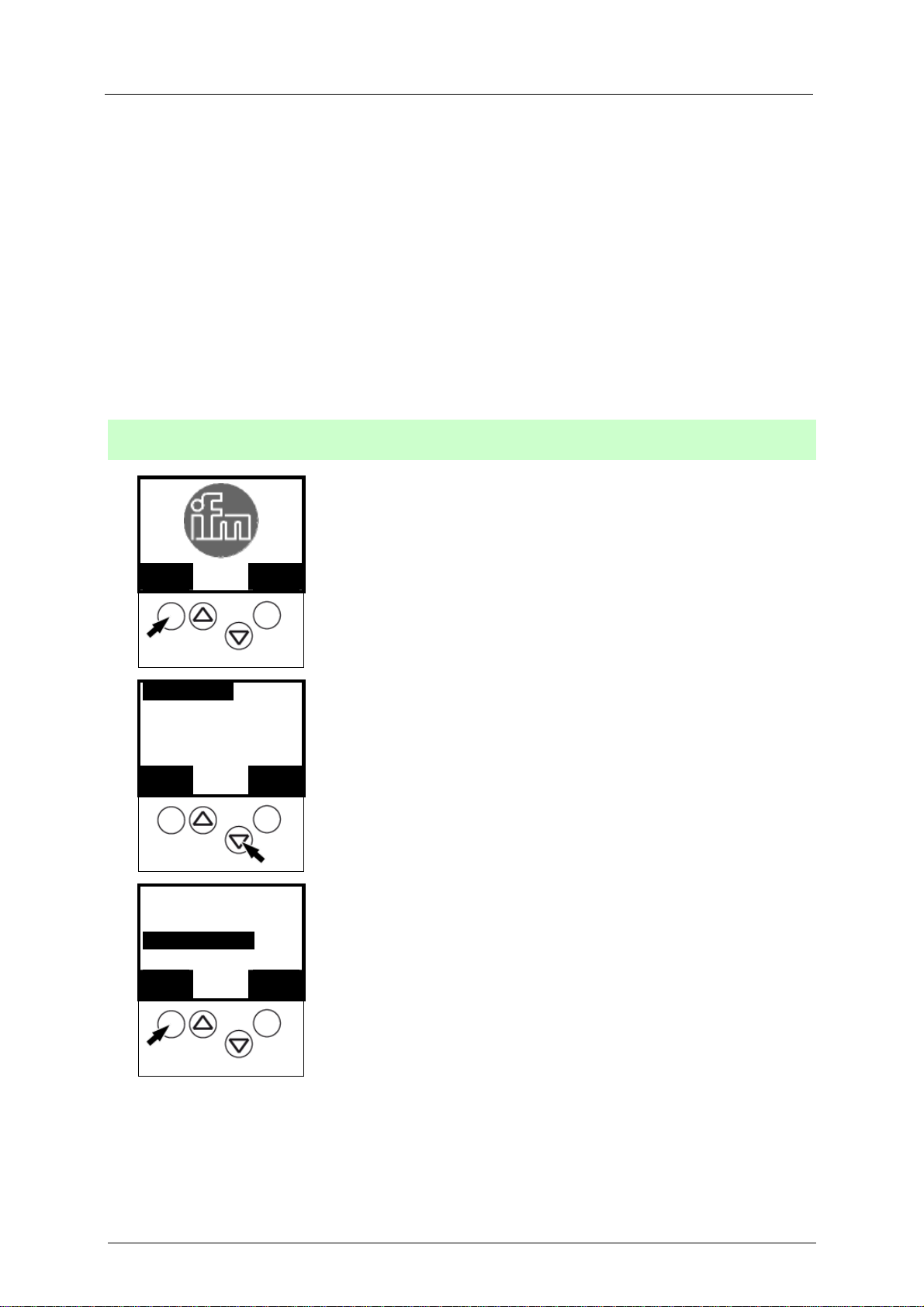
7.1.2 Set the parameters of the fieldbus interface in the controllere
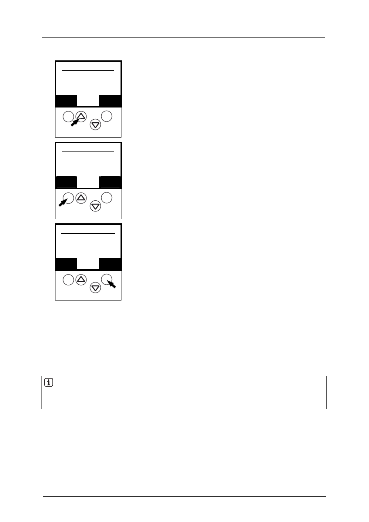
[Menu] > [Fieldbus Setup] > Choose address > [OK]
1.
MMEENNUU
Quick Setup
2.
PLC Setup
Slave Lists
OOKK
Diagnostics
3.
Master Setup
Fieldbus Setup
OOKK
0
1
▲ ▼
1
▲ ▼
UUSSEERR
EESSCC
EESSCC
► Press [MENU]
► Scroll to [Fieldbus Setup] with [▼]
► Select [Fieldbus Setup] with [OK].
7-1
Page 26
Set-up
Connect the controllere to the Profibus host
Fieldbus Address
4.
0
OOKK
Fieldbus Address
5.
OOKK
Fieldbus Baudrate
6.
#### KBaud
OOKK
87
▲ ▼
32
87
▲ ▼
88
▲ ▼
► Scroll to the requested address with [▲] / [▼].
EESSCC
► Save the fieldbus address with [OK].
EESSCC
> If there is communication with the fieldbus master:
display of negotiated baud rate
► Acknowledge with [OK].
EESSCC
> If there is no communication with the fieldbus master:
display value not defined
► Cancel with [ESC].
7.2 Connect the controllere to the Profibus host
► Connect the Profibus cable to the controllere.
7.3 Parameter setting of the Profibus host
NOTE
Refer to the description of the Profibus interface on the host
(host = fieldbus master = in most cases higher-level PLC)
GSD file
(GSD = General Station Description) The GSD file ifm604D8.gsd on the ifm CD contains different
possible definitions (indications of lengths) for each of the 12 modules, adapted to the controllere. →
Hardware catalogue of the Profibus configuration software in the gateway folder.
► Copy this file to the suitable directory of the corresponding fieldbus configuration program (→ its
description).
7-2
Page 27
Set-up
Parameter setting of the Profibus host
Programming software
The data of the controllere or the connected AS-i systems to be transferred can be defined (by
indicating the length of up to 12 modules) in the programming software for the Profibus DP master
system (host).
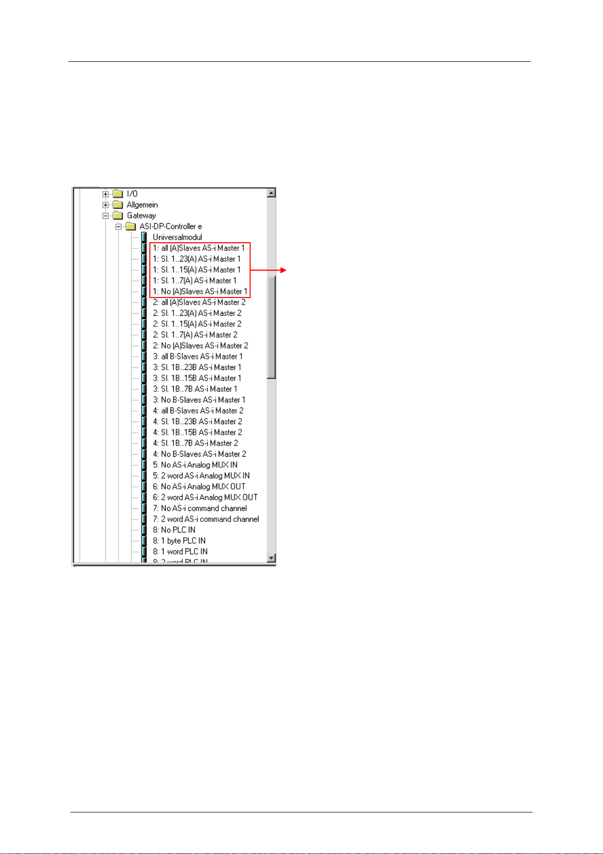
You can select from these definitions for parameter setting in the host:
Example for module 1:
There is a choice of 5 entries:
• all single and A slaves on AS-i master 1
(length = 16 bytes)
• single and A slaves with the addresses
1(A)...23(A) on AS-i master 1
(length = 12 bytes)
• single and A slaves with the addresses
1(A)...15(A) on AS-i master 1
(length = 8 bytes)
• single and A slaves with the addresses
1(A)...7(A) on AS-i master 1
(length = 4 bytes)
• no single or A slaves on AS-i master 1
(length = 0 bytes)
If the parameters for a smaller number of slaves than indicated in the selection point are to be set, you
have created free reserve in the host.
Example:
5 single and/or A slaves are connected to the AS-i master 1.
You have selected on the host:
"single and A slaves with the addresses 1(A)...7(A) on AS-i master 1"
You have then created an address area reserve of 1 byte in the host which is not used for the time being. The first 3 bytes of the
reserved address area are used to exchange data.
7-3
Page 28
Set-up
Parameter setting of the Profibus host
7.3.1 Assigning the addresses of the inputs/outputs to the host "locations"
For Profibus DP, virtual locations in the host are assigned to the inputs/outputs addressed via AS-i.
NOTE
Addressing of CTT2 and CTT3 slaves → separate basic instructions of the device manual
and there → chapter "Use of analogue channels in the controllere depending on the slave profile"
and → chapter "Data distribution of slaves to the M4 controllere"
Digital inputs / outputs
st
example:
1
Siemens S7 with AS-i controllere as gateway. The digital inputs/outputs on the AS-i controllere are
assigned to the host as bytes 0...15.
In this constellation, how are the IEC addresses distributed to the inputs and outputs of the slaves? →
next page
7-4
Page 29

Set-up
Parameter setting of the Profibus host
Digital inputs and outputs of the slaves at start address 0
Start address Bits 7...4 Bits 3...0
(Slave 0) reserved for master flags Slave 1
0
1
2
3
4
5
6
7
8
9
10
11
12
13
14
15
Reserved Conf.
Err.
0 .7 0 .6 0 .5 0 .4 0 .3 0 .2 0 .1 0 .0
D3 D2 D1 D0 D3 D2 D1 D0
1 .7 1 .6 1 .5 1 .4 1 .3 1 .2 1 .1 1 .0
D3 D2 D1 D0 D3 D2 D1 D0
2 .7 2 .6 2 .5 2 .4 2 .3 2 .2 2 .1 2 .0
D3 D2 D1 D0 D3 D2 D1 D0
3 .7 3 .6 3 .5 3 .4 3 .3 3 .2 3 .1 3 .0
D3 D2 D1 D0 D3 D2 D1 D0
4 .7 4 .6 4 .5 4 .4 4 .3 4 .2 4 .1 4 .0
D3 D2 D1 D0 D3 D2 D1 D0
5 .7 5 .6 5 .5 5 .4 5 .3 5 .2 5 .1 5 .0
D3 D2 D1 D0 D3 D2 D1 D0
6 .7 6 .6 6 .5 6 .4 6 .3 6 .2 6 .1 6 .0
D3 D2 D1 D0 D3 D2 D1 D0
7 .7 7 .6 7 .5 7 .4 7 .3 7 .2 7 .1 7 .0
D3 D2 D1 D0 D3 D2 D1 D0
8 .7 8 .6 8 .5 8 .4 8 .3 8 .2 8 .1 8 .0
D3 D2 D1 D0 D3 D2 D1 D0
9 .7 9 .6 9 .5 9 .4 9 .3 9 .2 9 .1 9 .0
D3 D2 D1 D0 D3 D2 D1 D0
10 .7 10 .6 10 .5 10 .4 10 .3 10 .2 10 .1 10 .0
D3 D2 D1 D0 D3 D2 D1 D0
11 .7 11 .6 11 .5 11 .4 11 .3 11 .2 11 .1 11 .0
D3 D2 D1 D0 D3 D2 D1 D0
12 .7 12 .6 12 .5 12 .4 12 .3 12 .2 12 .1 12 .0
D3 D2 D1 D0 D3 D2 D1 D0
13 .7 13 .6 13 .5 13 .4 13 .3 13 .2 13 .1 13 .0
D3 D2 D1 D0 D3 D2 D1 D0
14 .7 14 .6 14 .5 14 .4 14 .3 14 .2 14 .1 14 .0
D3 D2 D1 D0 D3 D2 D1 D0
15 .7 15 .6 15 .5 15 .4 15 .3 15 .2 15 .1 15 .0
No Slave PF.Err D3 D2 D1 D0
Slave 2 Slave 3
Slave 4 Slave 5
Slave 6 Slave 7
Slave 8 Slave 9
Slave 10 Slave 11
Slave 12 Slave 13
Slave 14 Slave 15
Slave 16 Slave 17
Slave 18 Slave 19
Slave 20 Slave 21
Slave 22 Slave 23
Slave 24 Slave 25
Slave 26 Slave 27
Slave 28 Slave 29
Slave 30 Slave 31
7-5
Page 30
Set-up
Parameter setting of the Profibus host
nd
example:
2
Siemens S7 with AS-i controllere as gateway. The digital inputs/outputs on the AS-i controllere are
assigned to the host as bytes 65...80.
In this constellation, how are the IEC addresses distributed to the inputs and outputs of the slaves? →
next page
7-6
Page 31

Set-up
Parameter setting of the Profibus host
Digital inputs and outputs of the slaves at start address 65
Start address Bits 7...4 Bits 3...0
(Slave 0) reserved for master flags Slave 1
65
66
67
68
69
70
71
72
73
74
75
76
77
78
79
80
Reserve
65 .7 65 .6 65 .5 65 .4 65 .3 65 .2 65 .1 65 .0
D3 D2 D1 D0 D3 D2 D1 D0
66 .7 66 .6 66 .5 66 .4 66 .3 66 .2 66 .1 66 .0
D3 D2 D1 D0 D3 D2 D1 D0
67 .7 67 .6 67 .5 67 .4 67 .3 67 .2 67 .1 67 .0
D3 D2 D1 D0 D3 D2 D1 D0
68 .7 68 .6 68 .5 68 .4 68 .3 68 .2 68 .1 68 .0
D3 D2 D1 D0 D3 D2 D1 D0
69 .7 69 .6 69 .5 69 .4 69 .3 69 .2 69 .1 69 .0
D3 D2 D1 D0 D3 D2 D1 D0
70 .7 70 .6 70 .5 70 .4 70 .3 70 .2 70 .1 70 .0
D3 D2 D1 D0 D3 D2 D1 D0
71 .7 71 .6 71 .5 71 .4 71 .3 71 .2 71 .1 71 .0
D3 D2 D1 D0 D3 D2 D1 D0
72 .7 72 .6 72 .5 72 .4 72 .3 72 .2 72 .1 72 .0
D3 D2 D1 D0 D3 D2 D1 D0
73 .7 73 .6 73 .5 73 .4 73 .3 73 .2 73 .1 73 .0
D3 D2 D1 D0 D3 D2 D1 D0
74 .7 74 .6 74 .5 74 .4 74 .3 74 .2 74 .1 74 .0
D3 D2 D1 D0 D3 D2 D1 D0
75 .7 75 .6 75 .5 75 .4 75 .3 75 .2 75 .1 75 .0
D3 D2 D1 D0 D3 D2 D1 D0
76 .7 76 .6 76 .5 76 .4 76 .3 76 .2 76 .1 76 .0
D3 D2 D1 D0 D3 D2 D1 D0
77 .7 77 .6 77 .5 77 .4 77 .3 77 .2 77 .1 77 .0
D3 D2 D1 D0 D3 D2 D1 D0
78 .7 78 .6 78 .5 78 .4 78 .3 78 .2 78 .1 78 .0
D3 D2 D1 D0 D3 D2 D1 D0
79 .7 79 .6 79 .5 79 .4 79 .3 79 .2 79 .1 79 .0
D3 D2 D1 D0 D3 D2 D1 D0
80 .7 80 .6 80 .5 80 .4 80 .3 80 .2 80 .1 80 .0
Conf.
Err.
NoSlave PF.Err D3 D2 D1 D0
Slave 2 Slave 3
Slave 4 Slave 5
Slave 6 Slave 7
Slave 8 Slave 9
Slave 10 Slave 11
Slave 12 Slave 13
Slave 14 Slave 15
Slave 16 Slave 17
Slave 18 Slave 19
Slave 20 Slave 21
Slave 22 Slave 23
Slave 24 Slave 25
Slave 26 Slave 27
Slave 28 Slave 29
Slave 30 Slave 31
7-7
Page 32

Set-up
Parameter setting of the Profibus host
Analogue inputs/outputs
1st example:
Siemens S7 with AS-i controllere as gateway.
The analogue inputs on the AS-i controllere are assigned to the host as bytes 256...287 (32 bytes = 16
words). The analogue outputs on the AS-i controllere are assigned to the host as bytes 256...271 (16
bytes = 8 words).
The order of the shown analogue slaves can be explicitly defined via parameters in the Profibus
configuration.
► To adapt the parameters, double-click on the controllere symbol.
► Change to the tab [Parameter Assignment] in the window which appears.
See figure:
7-8
Page 33

Set-up
Parameter setting of the Profibus host
In this constellation, how are the IEC addresses distributed to the inputs and outputs of the slaves?
The following tables show the correlation between start address and AS-i slave address (preset
parameters):
Analogue inputs
Start address [bytes] Slave address* Channel number
256 1
258 2
1
260 3
262
4
264 1
266 2
2
268 3
270
4
272 1
274 2
3
276 3
278
4
280 1
282 2
4
284 3
286
4
* The slave address can be freely assigned via the Profibus parameter data!
Analogue outputs
Start address [bytes] Slave address Channel number
256 1
258 2
1
260 3
262
4
264 1
266 2
2
268 3
270
4
* The slave address can be freely assigned via the Profibus parameter data!
7-9
Page 34

Set-up
Parameter setting of the Profibus host
Analogue inputs and outputs of the slaves at start address ###
SORRY - i n w o r k - SORRY
7-10
Page 35

Set-up
Parameter setting of the Profibus host
7.3.2 Assign PLC addresses to the Profibus modules
What are "Profibus modules"? These are entries in a parameter setting database of the programming
software for the Profibus DP master system (host). There you assign the individual "modules" to the
virtual "locations".
Locations are address areas for certain functions.
Modules are placeholders for certain address quantities within these areas.
The following IEC addresses are the designations for the PLC addresses in the controllere:
IEC address area
Description
from to
%IB1.1 %IB1.31 master 1, slaves 1A...31A, digital inputs
%IB2.1 %IB2.31 master 2, slaves 1A...31A, digital inputs
%IB11.1 %IB11.31 master 1, slaves 1B...31B, digital inputs
%IB12.1 %IB12.31 master 2, slaves 1B...31B, digital inputs
%IW21.1.x %IW21.31.x
%IW22.1.x %IW22.31.x
master 1, slaves 1...31,
analogue inputs x = channel*)
master 2, slaves 1...31,
analogue inputs x = channel *)
%IW0.0 %IW0.63 DP outputs for signal preprocessing
%IB0.128 %IB0.143
%IB0.144 %IB0.159
%IB0.160 %IB0.175
%IB0.176 %IB0.191
DP outputs for master1, slaves 1A...31A,
digital outputs
DP outputs for master1, slaves 1B...31B,
digital outputs
DP outputs for master2, slaves 1A...31A,
digital outputs
DP outputs for master 2, slaves 1B...31B,
digital outputs
Data flow
AS-i host
→
→
→
→
→
→
←
←
←
←
←
DP module
1 input
2 inputs
3 input
4 input
5 and 10
5 and 10
9
1 output
3 output
2 output
4 output
%IW0.96 %IW0.219
%IW0.224 %IW0.347
%IB0.704 %IB0.719
%IB0.720 %IB0.735
%IB0.736 %IB0.751
%IB0.752 %IB0.767
%QB1.1 %QB1.31
%QB2.1 %QB2.31
DP outputs for master 1, slaves 1...31,
analogue outputs
DP outputs for master 2, slaves 1...31,
analogue outputs
DP parameters for master 1, slaves
1A...31A, parameter data
DP parameters for master 1, slaves
1B...31B, parameter data
DP parameters for master 2, slaves
1A...31A, parameter data
DP parameters for master 2, slaves
1B...31B, parameter data
master 1, slaves 1A...31A,
digital outputs
master 2, slaves 1A...31A,
digital outputs
←
←
←
←
←
←
→
→
11
11
DP
parameters
DP
parameters
DP
parameters
DP
parameters
–
–
7-11
Page 36

Set-up
Parameter setting of the Profibus host
IEC address area
Description
from to
%QB11.1 %QB11.31
%QIB12.1 %QB12.31
%QW21.1.x %QW21.31.x
%QW22.1.x %QW22.31.x
master 1, slaves 1B...31B,
digital outputs
master 2, slaves 1B...31B,
digital outputs
master 1, slaves 1...31,
analogue outputs x = channel *)
master 2, slaves 1...31,
analogue outputs x = channel *)
%QW0.0 %QW0.63 signal preprocessing outputs for DP data
*) Channel numbers:
x = 0 → analogue channel 1
x = 1 → analogue channel 2
x = 2 → analogue channel 3
x = 3 → analogue channel 4
The following device behaviour is defined:
a) 1 channel per I/O slave
Word no. AS-i master no. Slave no. Channel
1 1
2 2
3 3
… …
30
31 1
32 2
33 3
… …
60
b) 2 channels per I/O slave
Word no. AS-i master no. Slave no. Channel
1 1
2
3 1
4
… …
59 1
60
1
30
2
30
1
1
2
30
Data flow
AS-i host
→
→
→
→
→
DP module
–
–
–
–
8
1
2
2
2
NOTE
All outputs will be reset when changing to the PLC operating mode "Stop"!
analogue outputs = 0,
digital outputs = FALSE
7-12
Page 37

Set-up
Parameter setting of the Profibus host
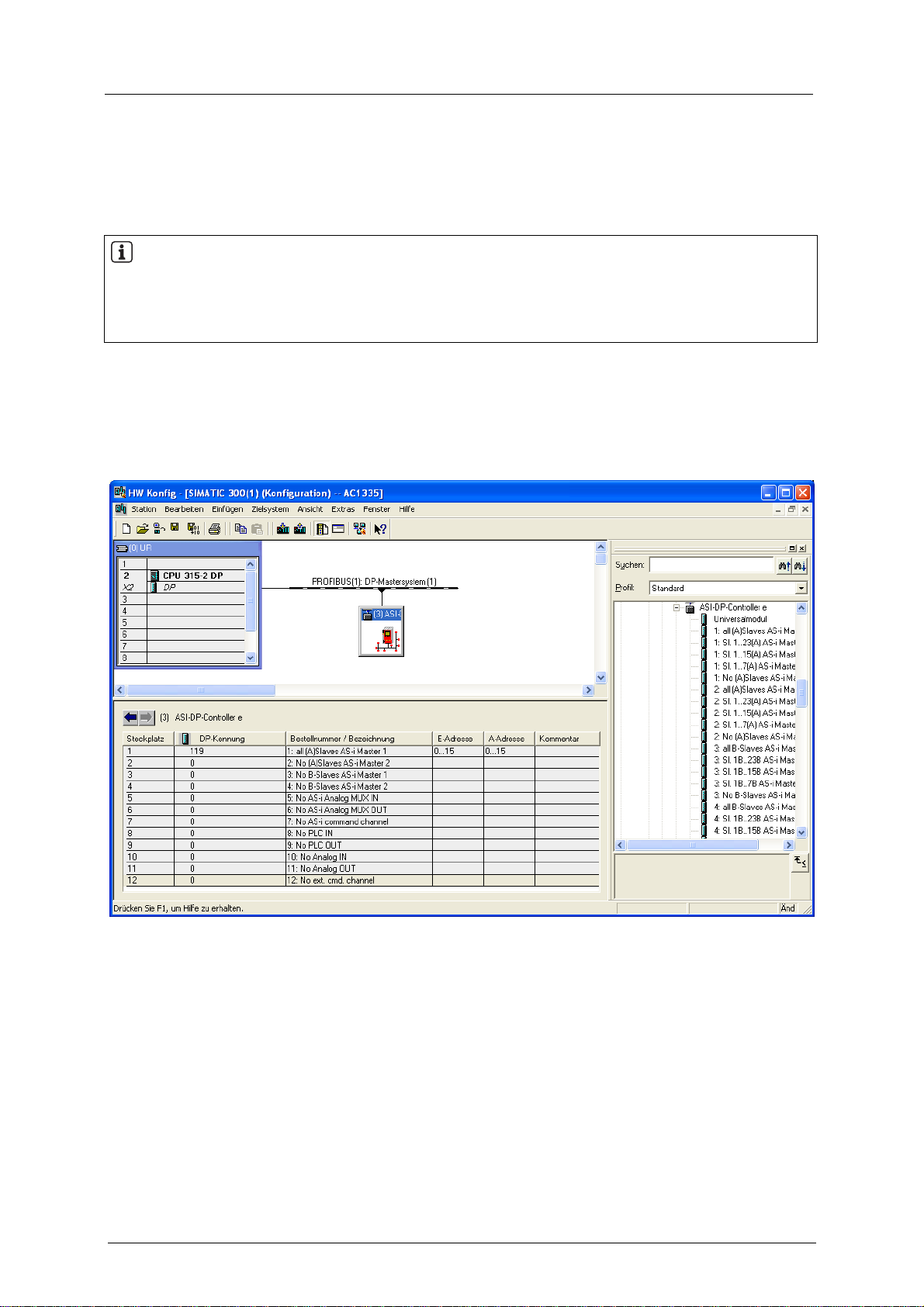
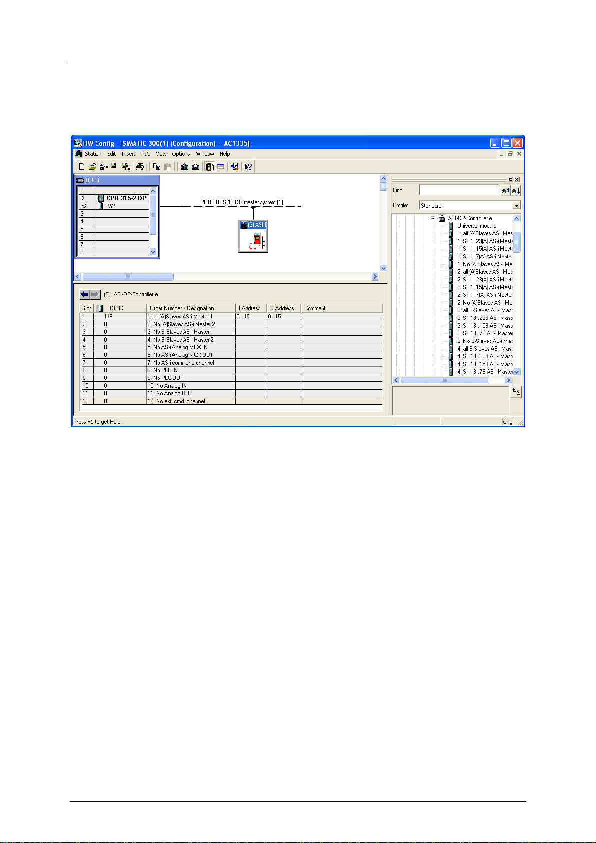
7.3.3 Define Profibus DP modules
The text of the different options of the modules always starts with the module number ( → photo page
7-3, section Programming software). So all options in the module list of the hardware catalogue
starting with "1:" are options of the first module in the device definition.
The first module for example defines the number of binary I/O data bytes of single or A slaves of AS-i
master 1 in the controllere which are to be transferred to the Profibus master via Profibus DP.
NOTE
The maximum data length of all 12 modules must not exceed 152 input bytes and 152 output bytes.
Example: Siemens S7
For the advanced Profibus DP user it is also possible to use length codes other than those indicated
as long as the maximum lengths of the modules are not exceeded.
7-13
Page 38

Set-up
Parameter setting of the Profibus host
Module 1: Binary inputs/outputs of single / A slaves of AS-i master 1
Contents Binary inputs and outputs of single or A slaves of AS-i master 1
Length 0...16 bytes I/O (if not used: length = 0)
Byte no. Bits 4...7 Bits 0...3
1 flags master 1 slave1(A)
2 slave2(A) slave3(A)
3 slave4(A) slave5(A)
4 slave6(A) slave7(A)
5 slave8(A) slave9(A)
6 slave10(A) slave11(A)
7 slave12(A) slave13(A)
8 slave14(A) slave14(A)
9 slave16(A) slave15(A)
10 slave18(A) slave19(A)
11 slave20(A) slave21(A)
12 slave22(A) slave23(A)
13 slave24(A) slave25(A)
14 slave26(A) slave27(A)
15 slave28(A) slave29(A)
16 slave30(A) slave31(A)
The flags in the first input byte contain status information of the AS-i master 1:
Bit 7 Bit 6 Bit 5 Bit 4
PLC running in the
controllere
Configuration error in
the AS-i circuit
AS-i master offline Periphery fault
The flags in the first output byte contain control information of the AS-i master 1:
Bit 7 Bit 6 Bit 5 Bit 4
Reserved Reserved
Reset of the stored
diagnostic data
Activate transfer of the
stored diagnostic data
If bit 4 of the control information is TRUE, the controllere transmits the stored periphery faults and
configuration errors in the device-specific diagnosis. The flags remain TRUE even if the fault is no
longer present. Bit 5 in the control information resets this information.
7-14
Page 39

Set-up
Parameter setting of the Profibus host
Module 2: Binary inputs/outputs of single / A slaves of AS-i master 2
Contents Binary inputs and outputs of single or A slaves of AS-i master 2
Length 0...16 bytes I/O (if not used: length = 0)
Byte no. Bits 4...7 Bits 0...3
1 flags master 2 slave1(A)
2 slave2(A) slave3(A)
3 slave4(A) slave5(A)
4 slave6(A) slave7(A)
5 slave8(A) slave9(A)
6 slave10(A) slave11(A)
7 slave12(A) slave13(A)
8 slave14(A) slave14(A)
9 slave16(A) slave15(A)
10 slave18(A) slave19(A)
11 slave20(A) slave21(A)
12 slave22(A) slave23(A)
13 slave24(A) slave25(A)
14 slave26(A) slave27(A)
15 slave28(A) slave29(A)
16 slave30(A) slave31(A)
The flags in the first input byte contain status information of AS-i master 2:
Bit 7 Bit 6 Bit 5 Bit 4
PLC running in the
controllere
Configuration error
in the AS-i circuit
No AS-i slave
detected
Periphery fault
The flags in the first output byte contain control information of the AS-i master 2:
Bit 7 Bit 6 Bit 5 Bit 4
Reserved Reserved
Reset of the stored
diagnostic data
Activate transfer of
the stored
diagnostic data
If bit 4 of the control information is TRUE, the controllere transmits the stored periphery faults and
configuration errors in the device-specific diagnosis. The flags remain TRUE even if the fault or error is
no longer present. Bit 5 in the control information resets this information.
7-15
Page 40

Set-up
Parameter setting of the Profibus host
Module 3: Binary inputs/outputs of B slaves of AS-i master 1
Contents Binary inputs and outputs of B slaves of the AS-i master 1
Length 0...16 bytes I/O (if not used: length = 0)
Byte no. Bits 4...7 Bits 0...3
1 reserved slave1B
2 slave2B slave3B
3 slave4B slave5B
4 slave6B slave7B
5 slave8B slave9B
6 slave10B slave11B
7 slave12B slave13B
8 slave14B slave14B
9 slave16B slave15B
10 slave18B slave19B
11 slave20B slave21B
12 slave22B slave23B
13 slave24B slave25B
14 slave26B slave27B
15 slave28B slave29B
16 slave30B slave31B
7-16
Page 41

Set-up
Parameter setting of the Profibus host
Module 4: Binary inputs/outputs of B slaves of AS-i master 2
Contents Binary inputs and outputs of B slaves of AS-i master 2
Length 0...16 bytes I/O (if not used: length = 0)
Byte no. Bits 4…7 Bits 0…3
1 reserved slave1B
2 slave2B slave3B
3 slave4B slave5B
4 slave6B slave7B
5 slave8B slave9B
6 slave10B slave11B
7 slave12B slave13B
8 slave14B slave14B
9 slave16B slave15B
10 slave18B slave19B
11 slave20B slave21B
12 slave22B slave23B
13 slave24B slave25B
14 slave26B slave27B
15 slave28B slave29B
16 slave30B slave31B
7-17
Page 42

Set-up
Parameter setting of the Profibus host
Module 5: Analogue inputs of AS-i master
Contents Multiplexed analogue inputs of AS-i master 1 and 2
Length 2-word consistent I/O ( if not used: length = 0)
DP master request (only 1 word)
Bit:
Word
15 14 13 12 11 10 9 8 7 6 5 4 3 2 1 0
1st
Legend
MM 2 bits Master no. 1...2
X 1 bit Slave type 0 = single or A slave
SSSSS 5 bits Slave no. 1…31
CC 2 bits Channel no. 0...3
MM X SSSSS 0 0 0 0 0 0 CC
1 = B slave
dec
dec
Calculation of the more significant byte (MMXSSSSS):
(slave no.) + (master no. * 64
dec
) + (32
, if B slave)
dec
Controllere response (2 words, first word copy of the request):
Bit:
Word
2nd
Legend
MM 2 bits Master no. 1...2
X 1 bit Slave type 0 = single or A slave
SSSSS 5 bits Slave no. 1…31
E1 1 bits Error no. of the response 0 = ok
E2 1 bits Error no. of the response 0 = ok
E3 1 bits Error no. of the response 0 = ok
E4 1 bits Error no. of the response 0 = ok
CC 2 bits Channel no. 0...3
15 14 13 12 11 10 9 8 7 6 5 4 3 2 1 0
1st
MM X SSSSS E4 E3 E2 E1 0 0 CC
Analogue value, INTEGER
1 = B slave
dec
1 = value invalid (of slave)
1 = overflow
1 = no analogue slave found
1 = protocol fault
dec
7-18
Page 43

Set-up
Parameter setting of the Profibus host
Module 6: Analogue outputs of AS-i master
Contents Multiplexed analogue outputs of AS-i master 1 and 2
Length 2-word consistent I/O (if not used: length = 0)
NOTE
If analogue outputs are also triggered in module 11, the value written in module 6 is overwritten with
the data of module 11.
DP master request (2 words)
Bit:
Word
15 14 13 12 11 10 9 8 7 6 5 4 3 2 1 0
1st
2nd
Legend
MM 2 bits Master no. 1...2
X 1 bits Slave type 0 = single or A slave
SSSSS 5 bits Slave no. 1…31
V 1 bits Switch off the channel 1 = TRUE
CC 2 bits Channel no. 0…3
MM X SSSSS 0 0 0 V 0 0 CC
Analogue value, INTEGER
1 = B slave
dec
→ switch off the channel,
master transmits "invalid"
Calculation of the more significant byte (MMXSSSSS):
(slave no.) + (master no. * 64
dec
) + (32
, if B slave)
dec
Controllere response (2 words, copy of the request):
Bit:
Word
2nd
Legend
MM 2 bits Master no. 1...2
X 1 bits Slave type 0 = single or A slave
SSSSS 5 bits Slave no. 1…31
E1 1 bits Error no. of the response 0 = not used
E2 1 bits Error no. of the response 0 = ok
E3 1 bits Error no. of the response 0 = ok
E4 1 bits Error no. of the response 0 = ok
CC 2 bits Channel no. 0...3
15 14 13 12 11 10 9 8 7 6 5 4 3 2 1 0
1st
MM X SSSSS E4 E3 E2 E1 0 0 CC
Analogue value, INTEGER
1 = B slave
dec
1 = protocol error (timeout)
1 = no analogue slave found
1 = protocol fault
7-19
Page 44

Set-up
Parameter setting of the Profibus host
Module 7: Command channel
Contents Command channel
→ page
8-1, chapter DP module 7: Command channel
Length 4-byte consistent I/O (if not used: length = 0)
IMPORTANT: For the query read only the required bytes. Unused bytes can
contain information of previous queries.
DP master request (4 bytes)
Bit
7 6 5 4 3 2 1 0
Byte
1
2
3
4
MM X SSSSS
→ Tables starting on the next page
→ Tables starting on the next page
Command no.
Calculation (MMXSSSSS):
(slave no.) + (master no. * 64
dec
) + (32
, if B slave)
dec
Controllere response (4 bytes, copy of the request)
Bit
7 6 5 4 3 2 1 0
Byte
1
2
3
4
Legend
D7 1 bit Error code 0 = no error occurred
D6 1 bit Command code 0 = command processed, buffer response valid
MM 2 bits Master no. 1...2
X 1 bit Slave type 0 = single or A slave
SSSSS 5 bits Slave no. 1…31
D7 D6 Command no.
MM X SSSSS
→ Tables starting on the next page
→ Tables starting on the next page
1 = error occurred during command processing
1 = command being processed, channel occupied
1 = B slave
dec
7-20
Page 45

Set-up
Parameter setting of the Profibus host
The commands are only executed if the command number (the first byte) changes. If the same
command is to be executed with different data several times (e.g. read slave lists), the operating mode
"continuous command" must first be selected for the data transfer. This is done with the command 62.
Overview of the commands in the DP module 7
Com
no.
1
2
3
4
5
6
7
8
Description Byte 2 Byte 3 Byte 4
► read master flags
> response:
► change operating mode
> response:
► read current slave configuration
> response:
► read projected slave configuration
> response:
► change projected slave
configuration
> response:
► read slave parameters
> response:
► change projected slave parameters
(default parameters)
> response:
► read LAS
> response:
MM000000
MM000000
MM000000
MM000000
MMXSSSSS
MMXSSSSS
MMXSSSSS
MMXSSSSS
MMXSSSSS
MMXSSSSS
MMXSSSSS
MMXSSSSS
MMXSSSSS
MMXSSSSS
MMXSSSSS
MMXSSSSS
0 –
master flags → page 8-2
AS-i master preset
operating mode
AS-i master current
operating mode
–
–
– –
slave configuration data
– –
slave configuration data
slave configuration data
slave configuration data
– –
projected
parameters
projected
parameters
projected
parameters
current parameters
–
–
– –
slave addresses from address group
► read LDS
MMXSSSSS
– –
9
> response:
► read LPF
MMXSSSSS
MMXSSSSS
slave addresses from address group
– –
10
> response:
► read LPS
MMXSSSSS
MMXSSSSS
slave addresses from address group
– –
11
slave addresses from address group
– –
12
> response:
MMXSSSSS
reserved – –
► read telegram error counter
MMXSSSSS
13
> response:
► read configuration error counter
MMXSSSSS
MM000000
error counter
– –
14
> response:
► read AS-i cycle counter
MM000000
MM000000
error counter
– –
15
> response:
MM000000
current count value of the cycle counter
7-21
Page 46

Set-up
Parameter setting of the Profibus host
Com
no.
16
17, 18
19
20
21
22
23
62
Description Byte 2 Byte 3 Byte 4
► change current slave parameters
> response:
MMXSSSSS
MMXSSSSS
parameters
reflected
parameters
–
–
reserved – – –
► config all
> response:
MM000000
MM000000
– –
status
–
reserved – – –
► save configuration in flash
> response:
► reset telegram error counter
> response:
► address slave
> response:
► operating mode "continuous
command“
> response: 0
MM000000
MM000000
MMXSSSSS
MMXSSSSS
– –
– –
– –
– –
MMXSSSSS 00XSSSSS
MMXSSSSS
0
– –
preset command
mode
current command
mode
–
0 = deactivate
1 = activate
0 = deactivated
1 = activated
63
► no operation command without
function
– – –
> response: – – –
7-22
Page 47

Set-up
Parameter setting of the Profibus host
Module 8: data transfer between Profibus DP master and PLC in the controllere
Contents Field for the data transfer between the Profibus DP master system and the PLC
functions in the controllere
Length 0...64-word inputs (if not used: length = 0)
Module 9: data transfer between PLC in the controllere and Profibus DP master
Contents Field for the data transfer between the PLC functions in the controllere and the
Profibus DP master system
Length 0...64-word outputs (if not used: length = 0)
Module 10: parallel analogue inputs
Contents
Parallel analogue inputs of up to 30 AS-i slaves, 1/2/4 words per AS-i slave; the
slave number and the number of analogue channels can be defined by Profibus
DP parameters.
Data length = 4 words (preset) All 4 channels of a total of up to 15 slaves on master 1 and 2 are
Data length = 2 words From slave 1 (of up to 30 slaves) on master 1 onwards, the channels 1
Data length = 1 word From slave 1 (of up to 30 slaves) on master 1 and 2 onwards, channel 1
transmitted.
Selection of the slaves to be transmitted via Profibus DP device
parameters (→ chapter
7-25)
page
and 2 are transmitted.
is transmitted.
Length 0...60-word inputs (if not used: length = 0)
Module 11: parallel analogue outputs
Contents
Parallel analogue outputs of up to 30 AS-i slaves, 1/2/4 words per AS-i slave; the
slave number and the number of analogue channels can be defined by Profibus
DP parameters.
Data length = 4 words (preset) All 4 channels on a total of up to 15 slaves on master 1 and 2
Data length = 2 words On slave 1 (up to 30 slaves) on master 1, the channels 1 and 2 are
Data length = 1 word On slave 1 (up to 30 slaves) on master 1 and 2 , channel 1 is
are transmitted.
Selection of the slaves to be transmitted via Profibus DP device
parameters (→ chapter
page
7-25)
transmitted.
transmitted.
Device-specific Profibus DP parameters,
Device-specific Profibus DP parameters,
Length 0...60-word outputs (if not used: length = 0)
NOTE
If analogue outputs are also triggered in module 6, the value written in module 6 is overwritten with
the data of module 11.
7-23
Page 48

Set-up
Parameter setting of the Profibus host
Module 12: Extended command channel
Contents Extended command channel
Length 2...18-word consistent inputs/outputs (if not used: length = 0)
NOTE
In some controllers larger consistent data fields cannot be processed in the direct I/O address area;
special function calls are then required.
7-24
Page 49

Set-up
Device-specific Profibus DP parameters
7.4 Device-specific Profibus DP parameters
With up to 100 bytes of the device-specific Profibus parameters the addresses of the analogue input
slaves and analogue output slaves to be transferred in parallel can be defined and the parameters of
the connected AS-i slaves can be set.
7.4.1 Device-specific Profibus DP parameters (example)
Byte
100
Parameter
[hex]
Description
1 80
2 00
fixed device parameters
3 00
4 00
5 AE fixed value: start of the analogue input addresses
6
…
20
42
…
slaves 2, 4, 6, 8,...30 of master 1
21 AA fixed value: start of the analogue output addresses
22
…
36
37
41
…
slaves 1, 3, 5, 7,...29 of master 1
2F bit 5 = TRUE activates the extended diagnosis of the AS-i system via Profibus DP
1F bit 4 = TRUE activates the AS-i parameter download
37
…
1F
…
predefined parameters of the AS-i slaves
FF
Slave addresses in the Profibus parameter bytes 6…20 and 22...36
Bit: 7 6 5 4 3 2 1 0
MM X SSSSS
Legend
MM 2 bits Master no. 1…2
X 1 bit Slave type 0 = single or A slave
1 = B slave
SSSSS 5 bits Slave no. 1…31
dec
Calculation of the more significant byte (MMXSSSSS):
(slave no.) + (master no. * 64
dec
) + (32
Examples: Master 1 Slave 3(A) 1*64 + 3
Master 2 Slave 5(A) 2*64 + 5 = 133
Master 1 Slave 1B 1*64 + 1 + 32
Master 1 Slave 28(A) 1*64 + 28
, if B slave)
dec
= 67
= 97
= 92
dec
= 85
dec
dec
dec
= 43
= 61
= 5C
hex
hex
hex
hex
7-25
Page 50

Set-up
Device-specific Profibus DP parameters
7.4.2 Definitions in the GSD file
The definitions in the GSD file (GSD = General Station Description) enable easy access to the device
parameters if this is supported by the configuration tool of the Profibus DP master:
Example
Siemens Step 7
Byte 37
Bit 5 = TRUE
If the parameter "Extended Profibus Diag." is set to "Enabled", the controllere transmits the extended
diagnostic data described in the next section. This data generates a DP request for a diagnosis in
case of an error state in the controllere. Therefore for a Siemens PLC OB82 must be programmed to
react to this state, otherwise the PLC stops.
7-26
Page 51

Set-up
Finish set-up
For "Disabled" (default) the controllere only transmits the standard diagnosis. An AS-i error state has
no direct effect on the Profibus DP but must then be monitored otherwise by the PLC (using the bits
4..7 in the first byte or via the command channel).
Byte 37
Bit 4 = TRUE
7.5 Finish set-up
System behaviour ► Define the system behaviour in the fieldbus configuration program, e.g.
► Save the configuration
watchdog etc.
Start ► Start the DP master
If there is communication on the fieldbus:
> The menu [Fieldbus Setup] in the controllere successively shows the
settings configured in the DP master.
If watchdog activated:
> LED [Bus Failure] goes out.
► Transfer the configuration to the DP master
7-27
Page 52

Set-up
Finish set-up
7-28
Page 53

DP module 7: Command channel
List of commands in module 7
8 DP module 7: Command channel
→ page 7-21, table Overview of the commands in the DP module 7
8.1 List of commands in module 7
Command number
decimal
01 01 read master flags 8-2
02 02 change operating mode 8-3
03 03 read current slave configuration 8-4
04 04 read projected slave configuration 8-5
05 05 change projected slave configuration 8-6
06 06 read slave parameters 8-7
07 07 change projected slave parameters (default parameters) 8-8
08 08 read LAS (list of active slaves) 8-9
09 09 read LDS (list of detected slaves) 8-11
10 0A read LPF (list of slaves with periphery fault) 8-12
11 0B read LPS (list of projected slaves) 8-13
12 0C - reserved - –
13 0D read telegram error counter 8-14
14 0E read configuration error counter 8-15
15 0F read AS-i cycle counter 8-16
16 10 change current slave parameters 8-17
17 11 reserved –
18 12 reserved –
19 13 Config all 8-18
20 14 reserved –
21 15 save configuration in flash 8-19
22 16 reset telegram error counter 8-20
23 17 address slave 8-21
62 3E operating mode "continuous command“ 8-22
63 3F no operation command without function 8-23
Hexa-
decimal
Description
→ page
8-1
Page 54

DP module 7: Command channel
Module 7, command 1:
read master flags
8.2 Module 7, command 1: read master flags
Structure
Request of DP master
Bit
Byte
1
2
3
4
7 6 5 4 3 2 1 0
0 0 01
hex
MM 0
0
0
Response from controllere
Bit
Byte
1
2
3
4
7 6 5 4 3 2 1 0
D7 D6 0
0
→ table at the bottom
→ table at the bottom
master flags
Byte Bit If bit D6 = TRUE, then:
0 periphery of all connected slaves is ok (no periphery fault)
3
4
1 automatic addressing is enabled
2 exchange of data with the slaves is active
3...7 reserved
0 AS-i configuration ok
1 a slave 0 is detected
2 automatic addressing is enabled
3 automatic addressing is active
4 configuration mode active
5 normal mode is active
6 AS-i voltage error has occurred
7 offline phase completed
MM = master no. (1…2)
not used
not used
D6 = command code
D7 = error code
→ page
7-20, table at the bottom
8-2
Page 55

DP module 7: Command channel
Module 7, command 2:
change operating mode
8.3 Module 7, command 2: change operating mode
Request of DP master
Bit
Byte
1
2
3
4
7 6 5 4 3 2 1 0
0 0 02
hex
MM 0
0 = protected mode
1 = configuration mode
0
MM = master no. (1…2)
not used
not used *)
Response from controllere
Bit
Byte
1
2
3
4
7 6 5 4 3 2 1 0
D7 D6 02
hex
copy of the request
copy of the request
0
D6 = command code
D7 = error code
→ page
not used *)
7-20, table at the bottom
*) IMPORTANT: For the query read only the required bytes. Unused bytes can contain information of
previous queries.
8-3
Page 56

DP module 7: Command channel
Module 7, command 3:
read current slave configuration
8.4 Module 7, command 3: read current slave configuration
Structure
Request of DP master
Bit MM = master no. (1…2)
Byte
1
2
3
4
7 6 5 4 3 2 1 0
0 0 03
hex
MM X SSSSS
0
0
X = slave type (0…1)
0 = standard / A slave
1 = B slave
SSSSS = slave no. (0…31
not used *)
not used *)
dec
Response from controllere
Bit
Byte
1
2
3
4
7 6 5 4 3 2 1 0
D7 D6 03
hex
copy of the request
extended ID code 2 extended ID code 1
ID code IO configuration
D6 = command code
D7 = error code
→ page
7-20, table at the bottom
Example: read current slave configuration of slave 7B on AS-i master 1
Request of DP master
Byte no. Value [hex] Description
1 03 03 = command 3
(slave no. 7)
2 67
3 00 not used *)
4 00 not used *)
+ (master no. 1 * 64)
+ (32, if B slave)
= 103
= 67
hex
dec
)
Response from controller
Byte no. Value [hex] Description
1 03 copy of the request
2 67 copy of the request
3 EF
4 03
(corresponds to slave profile S 3.0.E = 2I/2O module with periphery fault detection)
e
E = extended ID code 2
F = extended ID code 1
0 = ID code
3 = IO configuration
*) IMPORTANT: For the query read only the required bytes. Unused bytes can contain information of
previous queries.
8-4
Page 57

DP module 7: Command channel
Module 7, command 4:
read projected slave configuration
8.5 Module 7, command 4: read projected slave configuration
Structure
Request of DP master
Bit MM = master no. (1…2)
Byte
1
2
3
4
7 6 5 4 3 2 1 0
0 0 04
hex
MM X SSSSS
0
0
X = slave type (0…1)
0 = standard / A slave
1 = B slave
SSSSS = slave no. (0…31
not used *)
not used *)
)
dec
Response from controllere
Bit
Byte
1
2
3
4
7 6 5 4 3 2 1 0
D7 D6 0
0
extended ID code 2 extended ID code 1
ID code IO configuration
D6 = command code
D7 = error code
→ page
7-20, table at the bottom
Example: Read projected slave configuration of slave 16(A) on AS-i master 1
Request of DP master
Byte no. Value [hex] Description
1 04 04 = command 4
(slave no. 16)
2 50
3 00 not used *)
4 00 not used *)
+ (master no. 1 * 64)
+ (32, if B slave)
= 80
= 50
dec
hex
Response from controller
Byte no. Value [hex] Description
1 00
2 00
3 EF
4 37
(corresponds to slave profile S 7.3.E = analogue input module with 4 inputs)
e
E = extended ID code 2
F = extended ID code 1
3 = ID code
7 = IO configuration
*) IMPORTANT: For the query read only the required bytes. Unused bytes can contain information of
previous queries.
8-5
Page 58

DP module 7: Command channel
Module 7, command 5:
change projected slave configuration
8.6 Module 7, command 5: change projected slave configuration
Structure
Request of DP master
Bit MM = master no. (1…2)
Byte
1
2
3
4
7 6 5 4 3 2 1 0
0 0 05
hex
MM X SSSSS
extended ID code 2 extended ID code 1
ID code IO configuration
X = slave type (0…1)
0 = standard / A slave
1 = B slave
SSSSS = slave no. (0…31
)
dec
Response from controllere
Bit
Byte
1
2
3
4
7 6 5 4 3 2 1 0
D7 D6 05
hex
copy of the request
copy of the request
copy of the request
D6 = command code
D7 = error code
→ page
7-20, table at the bottom
Example: change projected slave configuration of slave 1(A) on master 2
Request of DP master
Byte no. Value [hex] Description
1 05 05 = command 5
(slave no. 1)
2 81
3 6F
4 37
+ (master no. 2 * 64)
+ (32, if B slave)
= 129
= 81
hex
dec
6 = extended ID code 2
F = extended ID code 1
3 = ID code
7 = IO configuration
Response from controller
Byte no. Value [hex] Description
1 05 copy of the request
2 81 copy of the request
3 6F copy of the request
4 37 copy of the request
e
8-6
Page 59

DP module 7: Command channel
Module 7, command 6:
read slave parameter
8.7 Module 7, command 6: read slave parameter
Structure
Request of DP master
Bit MM = master no. (1…2)
Byte
1
2
3
4
7 6 5 4 3 2 1 0
0 0 06
hex
MM X SSSSS
0
0
X = slave type (0…1)
0 = standard / A slave
1 = B slave
SSSSS = slave no. (0…31
not used *)
not used *)
Response from controllere
Bit
Bytes
1
2
3
4
7 6 5 4 3 2 1 0
D7 D6 0
0
projected parameter
current parameter
D6 = command code
D7 = error code
→ page
7-20, table at the bottom
Example: Read slave parameter of slave 2(A) on AS-i master 1
Request of DP master
Byte no. Value [hex] Description
1 06 06 = command 6
(slave no. 2)
2 42
3 00 not used *)
4 00 not used *)
+ (master no. 1 * 64)
+ (32, if B slave)
= 66
= 42
dec
hex
)
dec
Response from controller
Byte no. Value [hex] Description
1 00
2 00
3 03 projected parameter
4 0F current parameter
e
*) IMPORTANT: For the query read only the required bytes. Unused bytes can contain information of
previous queries.
8-7
Page 60

DP module 7: Command channel
Module 7, command 7:
change projected slave parameters
8.8 Module 7, command 7: change projected slave parameters
NOTE
The projected parameters can only be changed if the AS-i master operates in the configuration mode.
Activation → page
Structure
Request of DP master
8-3
Bit MM = master no. (1…2)
Byte
1
2
3
4
7 6 5 4 3 2 1 0
0 0 07
hex
MM X SSSSS
projected parameter
0
X = slave type (0…1)
0 = standard / A slave
1 = B slave
SSSSS = slave no. (0…31
not used *)
)
dec
Response from controllere
Bit
Byte
1
2
3
4
7 6 5 4 3 2 1 0
D7 D6 0
0
copy of the request
0
D6 = command code
D7 = error code
→ page
not used *)
7-20, table at the bottom
Example: change projected slave parameters of slave 7B on AS-i master 1
Request of DP master
Byte no. Value [hex] Description
1 07 07 = command 7
(slave no. 7)
2 87
3 0F projected parameter
4 00 not used *)
+ (master no. 1 * 64)
+ (32, if B slave)
= 135
= 87
hex
dec
Response from controllere
Byte no. Value [hex] Description
1 00
2 00
3 0F copy of the request
4 00 not used *)
*) IMPORTANT: For the query read only the required bytes. Unused bytes can contain information of
previous queries.
8-8
Page 61

DP module 7: Command channel
Module 7, command 8:
read LAS (list of active slaves)
8.9 Module 7, command 8: read LAS (list of active slaves)
Slave group
The 2 feedback bytes can only give information about max. 16 slaves. Therefore the slaves are
divided in 4 groups (→ following table).
When querying the slave lists any slave number from the requested slave group is to be indicated.
Bit
Group
1
2
3
4
7 6 5 4 3 2 1 0 7 6 5 4 3 2 1 0
15(A) 14(A) 13(A) 12(A) 11(A) 10(A) 9(A) 8(A) 7(A) 6(A) 5(A) 4(A) 3(A) 2(A) 1(A) 0 *
31(A) 30(A) 29(A) 28(A) 27(A) 26(A) 25(A) 24(A) 23(A) 22(A) 21(A) 20(A) 19(A) 18(A) 17(A) 16(A)
15B 14B 13B 12B 11B 10B 9B 8B 7B 6B 5B 4B 3B 2B 1B res
31B 30B 29B 28B 27B 26B 25B 24B 23B 22B 21B 20B 19B 18B 17B 16B
Byte 3 Byte 4
*) LAS and LPS have no slave 0, therefore this bit is set to 0!
Structure
Request of DP master
Bit MM = master no. (1…2)
Byte
1
2
3
4
7 6 5 4 3 2 1 0
0 0 08
hex
MM X SSSSS
0
0
X = slave type (0…1)
0 = standard / A slave
1 = B slave
SSSSS = slave no. (0…31
not used *)
not used *)
)
dec
Response from controllere
Bit
Byte
1
2
3
4
7 6 5 4 3 2 1 0
D7 D6 08
hex
copy of the request
→ table above
→ table above
D6 = command code
D7 = error code
→ page
provides the addresses of the active slaves in this address
group
7-20, table at the bottom
*) IMPORTANT: For the query read only the required bytes. Unused bytes can contain information of
previous queries.
Example → next page
8-9
Page 62

DP module 7: Command channel
Module 7, command 8:
read LAS (list of active slaves)
Example: Read LAS (list of active slaves) of slave group 1 on master 1
Request of DP master
Byte no. Value [hex] Description
1 08 08 = command 8
(slave no. 2) → group 1
2 42
3 00 not used *)
4 00 not used *)
+ (master no. 1 * 64)
+ (32, if B slave)
= 66
= 42
dec
hex
Response from controller
e
Byte no. Value [hex] Description
1 08 copy of the request
2 42 copy of the request
03
3
4
hex
00000011
FE
hex
11111110
→ table page
=
slave 8(A) is active
bin
slave 9(A) is active
=
→ table page
slaves 1(A) to 7(A) are active
bin
8-9 group 1:
8-9 group 1:
*) IMPORTANT: For the query read only the required bytes. Unused bytes can contain information of
previous queries.
8-10
Page 63

DP module 7: Command channel
Module 7, command 9:
read LDS (list of detected slaves)
8.10 Module 7, command 9: read LDS (list of detected slaves)
The 2 feedback bytes can only give information about max. 16 slaves. Therefore the slaves are
divided into 4 groups (→ table page
Structure
Request of DP master
Bit
Byte
1
2
3
7 6 5 4 3 2 1 0
0 0 09
MM X SSSSS
0
8-9).
hex
MM = master no. (1…2)
X = slave type (0…1)
0 = standard / A slave
1 = B slave
SSSSS = slave no. (0…31
not used *)
)
dec
4
0
not used *)
Response from controllere
Bit
Byte
1
2
3
4
7 6 5 4 3 2 1 0
D7 D6 0
0
→ table page
→ table page
8-9
8-9
D6 = command code
D7 = error code
→ page
provides the addresses of the detected slaves in this
address group
7-20, table at the bottom
Example: Read LDS (list of detected slaves) of slave group 3 on AS-i master 2
Request of DP master
Byte no. Value [hex] Description
1 09 09 = command 9
(slave no. 5) → group 3
2 A5
3 00 not used *)
4 00 not used *)
+ (master no. 2 * 64)
+ (32, if B slave)
= 165
= A5
hex
dec
Response from controller
Byte no. Value [hex] Description
1 00
2 00
03
=
3
4
hex
00000011
FE
=
hex
11111110
bin
bin
e
→ table page
slaves 8B and 9B were detected
→ table page
slaves 1B to 7B were detected
8-9 group 3:
8-9 group 3:
*) IMPORTANT: For the query read only the required bytes. Unused bytes can contain information of
previous queries.
8-11
Page 64

DP module 7: Command channel
Module 7, command 10dec (0Ahex): read LPF (list of slaves with periphery fault)
8.11 Module 7, command 10
dec
(0A
hex
):
read LPF (list of slaves with periphery fault)
The 2 feedback bytes can only give information about max. 16 slaves. Therefore the slaves are
divided into 4 groups (→ table page
Structure
Request of DP master
Bit MM = master no. (1…2)
Byte
1
2
3
4
7 6 5 4 3 2 1 0
0 0 0A
MM X SSSSS
0
0
Response from controllere
Bit
Byte
1
2
7 6 5 4 3 2 1 0
D7 D6 0A
copy of the request
8-9).
hex
hex
X = slave type (0…1)
0 = standard / A slave
1 = B slave
SSSSS = slave no. (0…31
not used *)
not used *)
D6 = command code
D7 = error code
→ page
7-20, table at the bottom
)
dec
3
4
→ table page
→ table page
8-9
8-9
provides the addresses of the slaves with periphery fault in
this address group
Example: Read LPF (list of slaves with periphery fault) of slave group 2 on AS-i master 1
Request of DP master
Byte no. Value [hex] Description
1 0A 0A = command10
(slave no. 20) → group 2
2 54
3 00 not used *)
4 00 not used *)
+ (master no. 1 * 64)
+ (32, if B slave)
= 84
= 54
dec
hex
Response from controllere
Byte no. Value [hex] Description
1 0A copy of the request
2 54 copy of the request
02
=
3
4
hex
00000010
20
hex
00100000
→ table page
slave 26(A) signals periphery fault
bin
=
→ table page
slave 21(A) signals periphery fault
bin
8-9 group 2:
8-9 group 2:
*) IMPORTANT: For the query read only the required bytes. Unused bytes can contain information of
previous queries.
8-12
Page 65

DP module 7: Command channel
Module 7, command 11dec (0Bhex): read LPS (list of projected slaves)
8.12 Module 7, command 11
dec
(0B
hex
):
read LPS (list of projected slaves)
The 2 feedback bytes can only give information about max. 16 slaves. Therefore the slaves are
divided into 4 groups (→ table page
Structure
Request of DP master
Bit MM = master no. (1…2)
Byte
1
2
3
4
7 6 5 4 3 2 1 0
0 0 0B
MM X SSSSS
0
0
Response from controllere
Bit
Byte
1
2
7 6 5 4 3 2 1 0
D7 D6 0B
copy of the request
8-9).
hex
hex
X = slave type (0…1)
0 = standard / A slave
1 = B slave
SSSSS = slave no. (0…31
not used *)
not used *)
D6 = command code
D7 = error code
→ page
7-20, table at the bottom
)
dec
3
4
→ table page
→ table page
8-9
8-9
provides the addresses of the projected slaves in this
address group
Example: Read LPS (list of projected slaves) of slave group 2 on AS-i master 1
Request of DP master
Byte no. Value [hex] Description
1 0B 0B = command 11
(slave no. 20) → group 2
2 54
3 00 not used *)
4 00 not used *)
+ (master no. 1 * 64)
+ (32, if B slave)
= 84
= 54
dec
hex
Response from controllere
Byte no. Value [hex] Description
1 0B copy of the request
2 54 copy of the request
02
=
3
4
hex
00000010
FE
hex
11111110
→ table page
slave 26(A) is projected
bin
=
→ table page
slaves 17(A) to 23(A) are projected
bin
8-9 group 2:
8-9 group 2:
*) IMPORTANT: For the query read only the required bytes. Unused bytes can contain information of
previous queries.
8-13
Page 66

DP module 7: Command channel
Module 7, command 13dec (0Dhex): read telegram error counter
8.13 Module 7, command 13
dec
(0D
hex
):
read telegram error counter
Structure
Request of DP master
Bit MM = master no. (1…2)
Byte
1
2
3
4
Response from controllere
Bit
Byte
1
2
3
4
7 6 5 4 3 2 1 0
0 0 0D
hex
MM X SSSSS
0
0
7 6 5 4 3 2 1 0
D7 D6 0D
hex
copy of the request
error counter high byte
error counter low byte
X = slave type (0…1)
0 = standard / A slave
1 = B slave
SSSSS = slave no. (0…31
not used *)
not used *)
D6 = command code
D7 = error code
→ page
provides the number of errors during the exchange of data
between the slave and the master since power on or reset
7-20, table at the bottom
)
dec
Example: read telegram error counter of slave 1 on AS-i master 1
Request of DP master
Byte no. Value [hex] Description
1 0D 0D = command 13
(slave no. 1)
2 41
3 00 not used *)
4 00 not used *)
+ (master no. 1 * 64)
+ (32, if B slave)
= 65
= 41
dec
hex
Response from controllere
Byte no. Value [hex] Description
1 0D copy of the request
2 41 copy of the request
3 00
4 20
hex
= 32
error counter = 0020
counter 32 faulty telegrams have occurred during data exchange.
dec
= 0032
hex
→ Since the last power-on of the controllere or reset of the
dec
*) IMPORTANT: For the query read only the required bytes. Unused bytes can contain information of
previous queries.
8-14
Page 67

DP module 7: Command channel
Module 7, command 14dec (0Ehex): read configuration error counter
8.14 Module 7, command 14
dec
(0E
hex
):
read configuration error counter
Structure
Request of DP master
Bit MM = master no. (1…2)
Byte
1
2
3
4
Response from controllere
Bit
Byte
1
2
3
4
7 6 5 4 3 2 1 0
0 0 0E
hex
MM 0
0
0
7 6 5 4 3 2 1 0
D7 D6 0E
hex
copy of the request
error counter high byte
error counter low byte
not used *)
not used *)
D6 = command code
D7 = error code
→ page
provides the number of configuration errors of the master
since power on or reset
7-20, table at the bottom
Example: read configuration error counter on AS-i master 2
Request of DP master
Byte no. Value [hex] Description
1 0E 0E = command 14
2 80
3 00 not used *)
4 00 not used *)
(master no. 2 * 64)
= 80
= 128
dec
hex
Response from controllere
Byte no. Value [hex] Description
1 0E copy of the request
2 80 copy of the request
3 00
4 03
error counter = 0003
→Since the last power-on of the controllere or the reset of the counter, 3 configuration errors
have occurred.
= 0003
hex
dec
*) IMPORTANT: For the query read only the required bytes. Unused bytes can contain information of
previous queries.
8-15
Page 68

DP module 7: Command channel
Module 7, command 15dec (0Fhex): read AS-i cycle counter
8.15 Module 7, command 15
dec
(0F
hex
):
read AS-i cycle counter
Structure
Request of DP master
Bit MM = master no. (1…2)
Byte
1
2
3
4
Response from controllere
Bit
Byte
1
2
3
4
7 6 5 4 3 2 1 0
0 0 0F
hex
MM 0
0
0
7 6 5 4 3 2 1 0
D7 D6 0F
hex
copy of the request
cycle counter high byte
cycle counter low byte
not used *)
not used *)
D6 = command code
D7 = error code
→ page
provides the number of AS-i cycles of the master since
power on
7-20, table at the bottom
Example: Read AS-i cycle counter of AS-i master 1
Request of DP master
Byte no. Value [hex] Description
1 0F 0F = command 15
2 40
3 00 not used *)
4 00 not used *)
(master no. 1 * 64)
= 40
= 64
dec
hex
Response from controllere
Byte no. Value [hex] Description
1 0F copy of the request
2 40 copy of the request
3 04
4 CA
cycle counter = 04CA
→ since the last power-on of the controllere, 1226 cycles have elapsed in the AS-i master 1
= 1226
hex
dec
By carrying out several measurements the number of cycles per time unit can be measured.
*) IMPORTANT: For the query read only the required bytes. Unused bytes can contain information of
previous queries.
8-16
Page 69

DP module 7: Command channel
Module 7, command 16dec (10hex): change current slave parameters
8.16 Module 7, command 16
dec
(10
hex
):
change current slave parameters
Structure
Request of DP master
Bit MM = master no. (1…2)
Byte
1
2
3
4
Response from controllere
Bit
Byte
1
2
3
7 6 5 4 3 2 1 0
0 0 10
hex
MM X SSSSS
preset value parameter
0
7 6 5 4 3 2 1 0
D7 D6 10
hex
copy of the request
feedback value parameter
X = slave type (0…1)
0 = standard / A slave
1 = B slave
SSSSS = slave no. (0…31
not used *)
D6 = command code
D7 = error code
→ page
feedback value can be different from preset value
7-20, table at the bottom
)
dec
4
0
not used *)
Example: Change slave parameter of slave 7 on AS-i master 1 to the value "F"
Request of DP master
Byte no. Value [hex] Description
1 10 10 = command 16
(slave no. 7)
2 47
3 0F preset value parameter
4 00 not used *)
+ (master no. 1 * 64)
+ (32, if B slave)
= 71
= 47
dec
hex
Response from controllere
Byte no. Value [hex] Description
1 10 copy of the request
2 47 copy of the request
3 0F feedback value can be different from preset value
4 00 not used *)
*) IMPORTANT: For the query read only the required bytes. Unused bytes can contain information of
previous queries.
8-17
Page 70

DP module 7: Command channel
Module 7, command 19dec (13hex): config. all
8.17 Module 7, command 19
config. all
Structure
Request of DP master
Bit
Byte
1
2
3
4
Response from controllere
Bit
Byte
1
2
3
7 6 5 4 3 2 1 0
0 0 13
hex
MM 0
0
0
7 6 5 4 3 2 1 0
D7 D6 13
hex
copy of the request
status
dec
(13
):
hex
MM = master no. (1…2)
not used *)
not used *)
D6 = command code
D7 = error code
→ page
7-20, table at the bottom
4
0
not used *)
Example: Config all on AS-i master 1
Request of DP master
Byte no. Value [hex] Description
1 13 13 = command 19
2 40
3 00 not used *)
4 00 not used *)
(master no. 1 * 64)
= 40
= 64
dec
hex
Response from controllere
Byte no. Value [hex] Description
1 13 copy of the request
2 40 copy of the request
3 80 status
4 00 not used *)
*) IMPORTANT: For the query read only the required bytes. Unused bytes can contain information of
previous queries.
8-18
Page 71

DP module 7: Command channel
Module 7, command 21dec (15hex): save configuration in flash
8.18 Module 7, command 21
dec
(15
hex
):
save configuration in flash
Structure
Request of DP master
Bit MM = master no. (1…2)
Byte
1
2
3
4
Response from controllere
Bit
Byte
1
2
3
7 6 5 4 3 2 1 0
0 0 15
hex
MM 0
0
0
7 6 5 4 3 2 1 0
D7 D6 15
hex
copy of the request
0
not used *)
not used *)
D6 = command code
D7 = error code
→ page
not used *)
7-20, table at the bottom
4
0
not used *)
Example: Save AS-i configuration in flash for AS-i master 1
Request of DP master
Byte no. Value [hex] Description
1 15 15 = command 21
2 40
3 00 not used *)
4 00 not used *)
(master no. 1 * 64)
= 40
= 64
dec
hex
Response from controllere
Byte no. Value [hex] Description
1 15 copy of the request
2 40 copy of the request
3 00 not used *)
4 00 not used *)
*) IMPORTANT: For the query read only the required bytes. Unused bytes can contain information of
previous queries.
8-19
Page 72

DP module 7: Command channel
Module 7, command 22dec (16hex): reset telegram error counter of a slave
8.19 Module 7, command 22
dec
(16
hex
):
reset telegram error counter of a slave
Structure
Request of DP master
Bit MM = master no. (1…2)
Byte
1
2
3
4
Response from controllere
Bit
Byte
1
2
3
7 6 5 4 3 2 1 0
0 0 16
hex
MM X SSSSS
0
0
7 6 5 4 3 2 1 0
D7 D6 16
hex
copy of the request
0
X = slave type (0…1)
0 = standard / A slave
1 = B slave
SSSSS = slave no. (0…31
not used *)
not used *)
D6 = command code
D7 = error code
→ page
not used *)
7-20, table at the bottom
)
dec
4
0
not used *)
Example: reset telegram error counter of slave 7(A) on AS-i master 2
Request of DP master
Byte no. Value [hex] Description
1 16 16 = command 22
(slave no. 7)
2 87
3 00 not used *)
4 00 not used *)
+ (master no. 2 * 64)
+ (32, if B slave)
= 135
= 87
hex
dec
Response from controllere
Byte no. Value [hex] Description
1 16 copy of the request
2 87 copy of the request
3 00 not used *)
4 00 not used *)
*) IMPORTANT: For the query read only the required bytes. Unused bytes can contain information of
previous queries.
8-20
Page 73

DP module 7: Command channel
Module 7, command 23dec (17hex): address slave
8.20 Module 7, command 23
dec
(17
hex
):
address slave
IMPORTANT: The controller
Structure
Request of DP master
Bit MM = master no. (1…2)
Byte
1
2
3
7 6 5 4 3 2 1 0
0 0 17
MM X SSSSS
new slave address
4
Response from controllere
Bit
Byte
1
2
7 6 5 4 3 2 1 0
D7 D6 17
copy of the request
must be in the configuration mode.
e
X = slave type (0…1)
0 = standard / A slave
hex
0
hex
1 = B slave
SSSSS = slave no. (0…31
not used *)
D6 = command code
D7 = error code
→ page
7-20, table at the bottom
)
dec
3
4
copy of the request
error message
Example: address slave 2B on AS-i master 1 to 7B
Request of DP master
Byte no. Value [hex] Description
1 17 17 = command 23
(slave no. 2)
2 62
3 07 new slave address 7B
4 00 not used *)
+ (master no. 1 * 64)
+ (32, if B slave)
= 98
= 62
dec
hex
Response from controllere in case of an error
Byte no. Value [hex] Description
1 17 copy of the request
2 62 copy of the request
3 07 new slave address
4 14
Error codes
here: error: master is in the wrong operating mode
→ page 9-5
Error codes → page 9-5
*) IMPORTANT: For the query read only the required bytes. Unused bytes can contain information of
previous queries.
8-21
Page 74

DP module 7: Command channel
Module 7, command 62dec (3Ehex): operating mode "continuous command“
8.21 Module 7, command 62
dec
(3E
hex
):
operating mode "continuous command“
If the "continuous" mode is active, the current command is transferred in every cycle.
NOTE
The continuous mode influences the behaviour of the controllere. The mode should only be used for
read commands.
Structure
Request of DP master
Bit
Byte
1
2
3
4
7 6 5 4 3 2 1 0
0 0 3E
hex
0
01
hex
0
01
hex
0
changes the mode
reads the current status
commands are carried out cyclically
commands are only carried out if the command number
changes
Response from controllere
Bit
Byte
1
2
3
4
7 6 5 4 3 2 1 0
D7 D6 3E
hex
0
copy of the request
copy of the request
D6 = command code
D7 = error code
→ page
7-20, table at the bottom
Example: Activate the operating mode "continuous command"
Request of DP master
Byte no. Value [hex] Description
1 3E 3E = command 62
2 00
3 01 changes the mode
4 01 commands are carried out cyclically
Response from controllere
Byte no. Value [hex] Description
1 3E copy of the request
2 47 copy of the request
3 01 copy of the request
4 01 copy of the request
8-22
Page 75

DP module 7: Command channel
Module 7, command 63dec (3Fhex): no operation command without function
8.22 Module 7, command 63
dec
no operation command without function
Structure
Request of DP master
Bit
Byte
1
2
3
4
Response from controllere
Bit
Byte
1
2
3
7 6 5 4 3 2 1 0
0 0 3F
hex
0
0
0
7 6 5 4 3 2 1 0
D7 D6 3F
hex
copy of the request
copy of the request
(3F
):
hex
not used *)
not used *)
not used *)
D6 = command code
D7 = error code
→ page
7-20, table at the bottom
4
copy of the request
Example: no operation command
Request of DP master
Byte no. Value [hex] Description
1 3F 3F = command 63
2 00 not used *)
3 00 not used *)
4 00 not used *)
Response from controllere
Byte no. Value [hex] Description
1 3F copy of the request
2 00 copy of the request
3 00 copy of the request
4 00 copy of the request
*) IMPORTANT: For the query read only the required bytes. Unused bytes can contain information of
previous queries.
8-23
Page 76

DP module 7: Command channel
Module 7, command 63dec (3Fhex):
no operation command without function
8-24
Page 77

DP module 12: Extended command channel
List of extended commands in module 12
9 DP module 12: Extended command channel
The extended command channel serves for exchange of data between the AS-i controllere and the
Profibus host (PLC).
NOTE
In some controllers larger consistent data fields cannot be processed in the direct I/O address area.
Then, special function calls are required.
9.1 List of extended commands in module 12
Command number
decimal
00 00 no execution of a command 9-6
01 01 write parameters to a connected AS-i slave 9-7
03 03 adopt and store currently connected AS-i slaves in the configuration 9-9
04 04 list of projected AS-i slaves (LPS) 9-11
05 05 set the operating mode of the AS-i master 9-13
06 06 readdress a connected AS-i slave 9-15
07 07 set the auto address mode of the AS-i master 9-17
09 09 change the extended ID code 1 in the connected AS-i slave 9-18
10…20 0A…14 force analogue data transfer directly to / from 3 AS-i slaves in each case 9-20
21 15 read the ID string of an AS-i slave with profile S-7.4 9-25
26 1A read AS-i master version 9-28
28 1C deactivation of the slave reset when changing to the protected mode 9-29
31 1F
33 21 read the diagnosis string of an AS-i slave with profile S-7.4 9-35
34 22 read the parameter string of an AS-i slave with the profile S-7.4 9-37
35 23 write the parameter string of an AS-i slave with the profile S-7.4 9-38
36 24
37 25
38 26
39 27
50 32 read current configuration of slaves 0(A)...15(A) 9-55
51 33 read current configuration of slaves 16(A)...31(A) 9-56
52 34 read current configuration of slaves 1B...15B 9-57
53 35 read current configuration of slaves 16B...31B 9-58
54 36 read current parameters of a connected AS-i slaves 9-59
55 37 read current slave lists 9-61
hexa-
decimal
Description
one-time execution of the "Extended safety monitor protocol" in the "Safety at Work"
monitor
Available from master profile M4 onwards:
acyclic standard read call for an AS-i slave with CTT2 profile
(S-7.5.5, S-7.A.5 or S-B.A.5)
Available from master profile M4 onwards:
acyclic standard write call of an AS-i slave with CTT2 profile
(S-7.5.5, S-7.A.5 or S-B.A.5)
Available from master profile M4 onwards:
acyclic manufacturer-specific read call of an AS-i slave with CTT2 profile
(S-7.5.5, S-7.A.5 or S-B.A.5)
Available from master profile M4 onwards:
acyclic manufacturer-specific write call of an AS-i slave with CTT2 profile
(S-7.5.5, S-7.A.5 or S-B.A.5)
→ page
9-30
9-40
9-44
9-47
9-51
9-1
Page 78

DP module 12: Extended command channel
List of extended commands in module 12
Command number
decimal
56 38 read projected configuration of slaves 1(A)...15(A) 9-63
57 39 read projected configuration of slaves 16(A)...31(A) 9-64
58 3A read projected configuration of slaves 1B...15B 9-65
59 3B read projected configuration of slaves 16B...31B 9-66
96 60
97 61
102 66
105 69
hexa-
decimal
Description
store data non-volatilely in the flash memory of the controllere
carry out various settings in the controllere
read the status of controllere display
read the device properties of the controllere
→ page
9-67
9-68
9-69
9-71
9-2
Page 79

DP module 12: Extended command channel
Data structure
9.2 Data structure
Length: 2...18-word consistent inputs/outputs (if not used: length = 0)
Request of DP master
Bit
Word
15 14 13 12 11 10 9 8 7 6 5 4 3 2 1 0
The word 2 is reserved for 7.4 commands (if not used: word = 0).
1
2
R R M user ID command number
R R A/B slave address R R R length
3…18
Response from controllere (gateway)
Bit
Word
1
2
15 14 13 12 11 10 9 8 7 6 5 4 3 2 1 0
E B M reflected user ID reflected command number
TG
L32
slave address F R R R length
3…18
Legend
Name Description
A/B Bit for addressing A or B slaves
B Busy bit
E Error bit
F Error bit
L32 Number of parameter bytes = 32
Length 5 bits for the number of data bytes (0…16
M AS-i master bit
R reserved
Slave
address
TG Toggle
User ID 5 bits for user ID (0…31
A/B=0: A slave (or standard slave)
A/B=1: B slave (addition of 20
B=0: command executed, response in the buffer is valid
B=1: command in process, channel is used
E=0: no error detected
E=1: error occurred during execution of the command
F=0: no error detected during command execution 7.4
F=1: error occurred during command execution 7.4
L32=0: number of bytes to be sent < 32
L32=1: number of bytes to be sent = 32
DP master: data bytes to be sent
controllere: data bytes received
M=0: AS-i master 1
M=1: AS-i master 2
5 bits for AS-i slave address (0…31
(reflected by the controllere)
Value changes for each command execution
(reflected by the controllere)
or 32
hex
dec
dec
dec
dec
)
dec
)
dec
command data
command data
to the slave address)
)
dec
9-3
Page 80

DP module 12: Extended command channel
Data structure
User ID
NOTE
If a command is to be executed, the user ID must be changed! Changing the command number does
not start the execution.
If a command is to be executed several times, the user ID must be changed accordingly, e.g. by
counting up. Counting up should not take place until the preceding command has been completed (bit
D14 = 0).
1st word, bit 14
1st word, bit 15
0 = command executed, response in the buffer is valid
1 = command in process, channel is used
0 = no error detected
1 = error occurred during command execution
9-4
Page 81

DP module 12: Extended command channel
Error codes in the module 12
9.3 Error codes in the module 12
Value [hex] Description
01
02
03
04
05
06
07
08
09
0A
0B
0C faulty S-7.4 protocol sequence
0D S-7.4 protocol aborted (timeout)
0E invalid AS-i slave address for the S-7.4 protocol (e.g. B slaves)
0F AS-i slave has completed the S-7.4 string
10 AS-i S-7.4 no longer connected (no longer in LAS)
11 another S-7.4 transfer to the addressed AS-i slave is already active
12 the previous segmented S-7.4 transfer was not completed
13 invalid S-7.4 data length
14
16 timeout during command processing
17 wrong slave profile or
20 the command could not be processed within the specified time
E0...EF error detected by AS-i slave; note error code CTT2 (see below)
F0 invalid CTT2 command
F1 invalid CTT2 response
F2 7.5 data length longer than 30 bytes
no slave response or:
master is in the offline mode when calling the command
no slave with the old address found
slave with address 0 connected
no slave with the new address found
error when deleting the old address
error when reading the IO configuration
error when writing the new address or the extended ID code 1
new address could only be saved temporarily
extended ID code 1 could only be saved temporarily
slave is not in LAS
parameter or address invalid
master is in the wrong operating mode or
invalid S-7.4 command
slave not in LAS
master is not in the normal mode
9.4 CTT2 error code in module 12
Value [hex] Description
00 no error
01 invalid index
02 invalid length
03 command not implemented
04 occupied, command could not be completed in the specified time
05 command was not acknowledged
9-5
Page 82

DP module 12: Extended command channel
Module 12, extended command 0:
no execution of a command
9.5 Module 12, extended command 0: no execution of a command
Request of DP master
Word no. Value [hex] Description
1 0800
2…18 0000 not used
Response from controllere (gateway)
Word no. Value [hex] Description
1 0800
2…18 0000 not changed
08 = user ID changes e.g. to 8
00 = command number 0
08 = reflected user ID 8
00 = reflected command number 0
9-6
Page 83

DP module 12: Extended command channel
Module 12, extended command 1:
write parameters to a connected AS-i slave
9.6 Module 12, extended command 1: write parameters to a connected AS-i slave
Request of DP master
Bit
Word
1
2
3
4
15 14 13 12 11 10 9 8 7 6 5 4 3 2 1 0
0 0
M
0/1
user ID command number = 01
reserved = 0 reserved = 0
0 0 0
0 parameter value to be written
A/B
0/1
hex
slave address
5…18
ignored
Legend → page 9-3
Example:
Word no. Value [hex] Description
1 0901
2 0000 reserved
3 0024
4 000F parameter value to be written
M=0: AS-i master 1
09 = user ID changes e.g. to 9
01 = command number 1
slave address 4B
(for B slaves: bit 5 = 1 → add 20
to the address)
hex
Response from controllere (gateway) in the normal case
Bit
Word
1
2
3
15 14 13 12 11 10 9 8 7 6 5 4 3 2 1 0
E=0 B=0
M
0/1
reflected user ID reflected command number = 01
reserved = 0 reserved = 0
0 parameter value read back
hex
4…18
not changed
Legend → page 9-3
Example:
Word no. Value [hex] Description
1 0901
2 0000 reserved
3 000F parameter value read back
4…18 0000 not changed
M=0: AS-i master 1
09 = reflected user ID 9
01 = reflected command number 1
9-7
Page 84

DP module 12: Extended command channel
Module 12, extended command 1:
write parameters to a connected AS-i slave
Response from controllere (gateway) in case of an error
Bit
Word
1
2
15 14 13 12 11 10 9 8 7 6 5 4 3 2 1 0
E=1 B=0
M
0/1
reserved = 0 reserved = 0
3
4…18
Legend → page 9-3
Example:
Word no. Value [hex] Description
E=1: fault occurred during execution of the command
1 8901
2 0000 reserved
3 000A error code 0A
M=0: AS-i master 1
89 = reflected user ID 9
01 = reflected command number 1
Possible error codes
Value [hex] Description
01
0A
0B
14
no slave response or:
master is in the offline mode when calling the command
slave is not in LAS
parameter or address invalid
master is in the wrong operating mode
Here: master is not in the normal mode
reflected user ID reflected command number = 01
hex
0 Error code
ignored
= slave not in the LAS
hex
9-8
Page 85

DP module 12: Extended command channel
Module 12, extended command 3:
adopt and store connected AS-i slaves in the configuration
9.7 Module 12, extended command 3: adopt and store connected AS-i slaves in the configuration
Request of DP master
Bit
Word
1
2…18
Legend → page 9-3
Example:
Word no. Value [hex] Description
1 0C03
2…18 0000 not used
15 14 13 12 11 10 9 8 7 6 5 4 3 2 1 0
R R
M
0/1
user ID command number = 03
not used
M=0: AS-i master 1
0C = user ID changes e.g. to 12
03 = command number 3
hex
= 03
dec
Response from controllere (gateway) in the normal case
Bit
Word
1
2…18
15 14 13 12 11 10 9 8 7 6 5 4 3 2 1 0
E=0 B=0
M
0/1
reflected user ID reflected command number = 03
not changed
Legend → page 9-3
Example:
Word no. Value [hex] Description
1 0C03
2 0000 not changed
M=0: AS-i master 1
0C = reflected user ID 12
03 = reflected command number 3
hex
9-9
Page 86

DP module 12: Extended command channel
Module 12, extended command 3:
adopt and store connected AS-i slaves in the configuration
Response from controllere (gateway) in case of an error
Bit
Word
1
15 14 13 12 11 10 9 8 7 6 5 4 3 2 1 0
E=1 B=0
M
0/1
2
3
Legend → page 9-3
Example:
Word no. Value [hex] Description
E=1: fault occurred during execution of the command
1 1C03
2 0000 reserved
3 0014 error code 14
M=0: AS-i master 1
xC = reflected user ID 12
03 = reflected command number 3
Possible error codes
Value [hex] Description
14
master is in the wrong operating mode
here: master is not in the normal mode
reflected user ID reflected command number = 03
hex
reserved = 0
0 error code
= master is in wrong operating mode
hex
9-10
Page 87

DP module 12: Extended command channel
Module 12, extended command 4:
write LPS
9.8 Module 12, extended command 4: write LPS
Request of DP master
Bit
Word
1
2
15 14 13 12 11 10 9 8 7 6 5 4 3 2 1 0
R R
M
0/1
user ID command number = 04
reserved = 0
hex
= 04
dec
3
4
5
6
15(A) 14(A) 13(A) 12(A) 11(A) 10(A) 9(A) 8(A) 7(A) 6(A) 5(A) 4(A) 3(A) 2(A) 1(A) res.
31(A) 30(A) 29(A) 28(A) 27(A) 26(A) 25(A) 24(A) 23(A) 22(A) 21(A) 20(A) 19(A) 18(A) 17(A) 16(A)
15B 14B 13B 12B 11B 10B 9B 8B 7B 6B 5B 4B 3B 2B 1B res.
31B 30B 29B 28B 27B 26B 25B 24B 23B 22B 21B 20B 19B 18B 17B 16B
7…18
Legend → page 9-3
Example:
Word no. Value [hex] Description
1 0204
2 0000 reserved
3 001E
4 8000
5 0002 slave 1B *) is to be projected
6 0001 slave 16B *) is to be projected
M=0: AS-i master 1
02 = user ID changes e.g. to 2
04 = command number 4
slaves 1(A) to 5(A) *) are to be projected
001E
= 0000 0000 0001 1110
hex
slave 31(A) *) is to be projected
8000
= 1000 0000 0000 0000
hex
not used
bin
bin
9-11
Page 88

DP module 12: Extended command channel
Module 12, extended command 4:
write LPS
Response from controllere (gateway) in the normal case
Bit
Word
1
2…18
15 14 13 12 11 10 9 8 7 6 5 4 3 2 1 0
E=0 B=0
M
0/1
reflected user ID reflected command number = 04
not changed
Legend → page 9-3
Example:
Word no. Value [hex] Description
1 0204
2…18 0000 not changed
M=0: AS-i master 1
02 = reflected user ID 2
04 = reflected command number 4
Response from controllere (gateway) in case of an error
Bit
Word
1
2
3
15 14 13 12 11 10 9 8 7 6 5 4 3 2 1 0
E=1 B=0
M
0/1
reflected user ID reflected command number = 04
reserved = 0
0 error code
hex
hex
4…18
Legend → page 9-3
Example:
Word no. Value [hex] Description
E=1: fault occurred during execution of the command
1 8204
2 0000 reserved
3 0014 error code 14
M=0: AS-i master 1
82 = reflected user ID 2
04 = reflected command number 4
Possible error codes
Value [hex] Description
14
master is in the wrong operating mode
here: master is not in configuration mode
ignored
= master in wrong operating mode
hex
9-12
Page 89

DP module 12: Extended command channel
Module 12, extended command 5:
set the operating mode of the AS-i master
9.9 Module 12, extended command 5: set the operating mode of the AS-i master
Request of DP master
Bit
Word
1
2
15 14 13 12 11 10 9 8 7 6 5 4 3 2 1 0
R R
M
0/1
user ID command number = 05
reserved = 0 reserved = 0
hex
= 05
dec
3
4…18
0 0
not used
Legend → page 9-3 and
Mod set the operating mode of the AS-i master
Mod=0: activate protected mode
Mod=1: activate configuration mode
Example:
Word no. Value [hex] Description
1 0105
2 0000 reserved
3
0000 activate protected mode
0001 activate configuration mode
M=0: AS-i master 1
01 = user ID changes e.g. to 1
05 = command number 5
Response from controllere (gateway) in the normal case
Bit
Word
1
2…18
15 14 13 12 11 10 9 8 7 6 5 4 3 2 1 0
E=0 B=0
M
0/1
reflected user ID reflected command number = 05
not changed
Mod
hex
Example:
Word no. Value [hex] Description
1 0105
2…18 0000 not changed
M=0: AS-i master 1
01 = reflected user ID 1
05 = reflected command number 5
9-13
Page 90

DP module 12: Extended command channel
Module 12, extended command 5:
set the operating mode of the AS-i master
Response from controllere (gateway) in case of an error
Bit
Word
1
2
15 14 13 12 11 10 9 8 7 6 5 4 3 2 1 0
E=1 B=0
M
0/1
reserved = 0 reserved = 0
3
4…18
Legend → page 9-3
Example:
Word no. Value [hex] Description
E=1: fault occurred during execution of the command
1 8105
2 0000 reserved
3 0003 error code 03
M=0: AS-i master 1
01 = reflected user ID 1
05 = reflected command number 5
Possible error codes
Value [hex] Description
03 slave with the address 0 is connected
reflected user ID reflected command number = 05
hex
0 error code
ignored
= slave with the address 0 connected
hex
9-14
Page 91

DP module 12: Extended command channel
Module 12, extended command 6:
readdress a connected AS-i slave
9.10 Module 12, extended command 6: readdress a connected AS-i slave
Request of DP master
Bit
Word
1
2
3
4
5…18
Legend → page 9-3
Example:
Word no. Value [hex] Description
1 0806
2 0000 reserved
3 0029
4 000B new slave address 11A
15 14 13 12 11 10 9 8 7 6 5 4 3 2 1 0
R R
M
0/1
user ID Command number = 06
reserved = 0 reserved = 0
0 0 0
0 0 0
not used
M=0: AS-i master 1
08 = user ID changes e.g. to 8
06 = command number 6
old slave address 9B
(for B slaves: bit 5 = 1→ add 20
to the address)
hex
A/B
0/1
A/B
0/1
= 06
hex
dec
old slave address
new slave address
Response from controllere (gateway) in the normal case
Bit
Word
1
2…18
15 14 13 12 11 10 9 8 7 6 5 4 3 2 1 0
E=0 B=0
M
0/1
reflected user ID reflected command number = 06
not changed
Legend → page 9-3
Example:
Word no. Value [hex] Description
1 0806
2…18 0000 not changed
M=0: AS-i master 1
08 = reflected user ID 8
06 = reflected command number 6
hex
9-15
Page 92

DP module 12: Extended command channel
Module 12, extended command 6:
readdress a connected AS-i slave
Response from controllere (gateway) in case of an error
Bit
15 14 13 12 11 10 9 8 7 6 5 4 3 2 1 0
Word
1
2
E=1 B=0
M
0/1
reserved = 0 reserved = 0
3
4…18
Legend → page 9-3
Example:
Word no. Value [hex] Description
E=1: fault occurred during execution of the command
1 8806
M=0: AS-i master 1
88 = reflected user ID 8
06 = reflected command number 6
2 0000 reserved
3 0003 error code 03
Possible error codes
Value [hex] Description
01
02
03
04
05
06
07
08
09
0B
14
no slave response or:
master is in the offline mode when calling the command
no slave with the old address found
slave with address 0 connected
no slave with the new address found
error when deleting the old address
error when reading the IO configuration
error when writing the new address or the extended ID code 1
new address could only be saved temporarily
extended ID code 1 could only be saved temporarily
parameter or address invalid
master is in the wrong operating mode
here: master is not in the normal mode
reflected user ID reflected command number = 06
hex
0 error code
ignored
= slave with the address 0 connected
hex
9-16
Page 93

DP module 12: Extended command channel
Module 12, extended command 7:
set the auto address mode of the AS-i master
9.11 Module 12, extended command 7: set the auto address mode of the AS-i master
Request of DP master
Bit
Word
1
2
15 14 13 12 11 10 9 8 7 6 5 4 3 2 1 0
R R
M
0/1
user ID command number = 07
reserved = 0 reserved = 0
hex
= 07
dec
3
0 0
4…18
Legend → page 9-3 and
Mod Mode slave reset
Mod=0: offline phase when changing over to the protected mode
Mod=1: no offline phase when changing over to the protected mode
Example:
Word no. Value [hex] Description
1 0407
2 0000 reserved
3
0000 automatic addressing deactivated
0001 automatic addressing possible
M=0: AS-i master 1
04 = user ID changes e.g. to 4
07 = command number 7
Response from controllere (gateway)
Bit
Word
1
15 14 13 12 11 10 9 8 7 6 5 4 3 2 1 0
E=0 B=0
M
0/1
reflected user ID reflected command number = 07
2…18
Mod
not used
hex
not changed
Legend → page 9-3
Example:
Word no. Value [hex] Description
1 0407
2…18 0000 not changed
M=0: AS-i master 1
04 = reflected user ID 4
07 = reflected command number 7
9-17
Page 94

DP module 12: Extended command channel
Module 12, extended command 9:
change extended ID code 1 in the AS-i slave
9.12 Module 12, extended command 9: change extended ID code 1 in the AS-i slave
Request of DP master
Bit
Word
1
2
3
3
15 14 13 12 11 10 9 8 7 6 5 4 3 2 1 0
R R
M
0/1
user ID command number = 09
reserved = 0 reserved = 0
0 0 0
0 0
A/B
0/1
= 09
hex
dec
slave address
new extended ID code 1
4…18
not used
Legend → page 9-3
Example:
Word no. Value [hex] Description
1 0F09
2 0000 reserved
3 0011
4 0008 new extended ID code 1 = 8
M=0: AS-i master 1
0F = user ID changes e.g. to 15
09 = command number 9
slave address 17(A) → 11
(for B slaves: bit 5 = 1 → add 20
hex
to the address)
hex
Response from controllere (gateway) in the normal case
Bit
Word
1
2…18
15 14 13 12 11 10 9 8 7 6 5 4 3 2 1 0
E=0 B=0
M
0/1
reflected user ID reflected command number = 09
not changed
Legend → page 9-3
Example:
Word no. Value [hex] Description
1 0F09
2 0000 not changed
M=0: AS-i master 1
0F = reflected user ID 15
09 = reflected command number 9
hex
9-18
Page 95

DP module 12: Extended command channel
Module 12, extended command 9:
change extended ID code 1 in the AS-i slave
Response from controllere (gateway) in case of an error
Bit
Word
1
2
15 14 13 12 11 10 9 8 7 6 5 4 3 2 1 0
E=1 B=0
M
0/1
reserved = 0 reserved = 0
3
4…18
Legend → page 9-3
Example:
Word no. Value [hex] Description
E=1: fault occurred during execution of the command
1 8F09
2 0000 reserved
3 0007
M=0: AS-i master 1
8F = reflected user ID 15
09 = reflected command number 9
error code 07
here: slave does not support the extended ID code 1
Possible error codes
Value [hex] Description
01
02
03
07
09
0B
no slave response or:
master is in the offline mode when calling the command
no slave with the old address found
slave with address 0 connected
error when writing the new address or the extended ID code 1
extended ID code 1 could only be saved temporarily
parameter or address invalid
reflected user ID reflected command number = 09
hex
0 error code
ignored
= error when writing the new address or the extended ID code 1
hex
9-19
Page 96

DP module 12: Extended command channel
Module 12, extended command 10...20dec (0A...14hex): force analogue data transfer directly to / from 3 AS-i slaves in each case
9.13 Module 12, extended command 10...20
force analogue data transfer directly to / from 3 AS-i slaves in each
case
Request of DP master
Bit
Word
1
2
3
4
5
6
7
8
9
15 14 13 12 11 10 9 8 7 6 5 4 3 2 1 0
R R
M
0/1
user ID command number = 0A...14
reserved = 0 reserved = 0
output data AS-i slave 1(A), channel 0
output data AS-i slave 1(A), channel 1
output data AS-i slave 1, channel 2 or
output data AS-i slave 1B, channel 0
output data AS-i slave 1, channel 3 or
output data AS-i slave 1B, channel 1
reserved = 0
O3 V3 O2 V2 O1 V1 O0 V0
output data AS-i slave 2(A), channel 0
output data AS-i slave 2(A), channel 1
(0A...14
dec
hex
):
= 10...20
hex
dec
10
11
12
13
14
15
16
17
18
Legend → page 9-3 and
V0…V3 Valid
Vx=0: data invalid
Vx=1: data valid
Output data must be valid (V=1) to be enabled in the AS-i slave!
O0...O3 Overflow
Ox=0: data are in the valid range
Ox=1: data are in the invalid range
(especially in case of input modules, when the measuring range is not reached or exceeded)
output data AS-i slave 2, channel 2 or
output data AS-i slave 2B, channel 0
output data AS-i slave 2, channel 3 or
output data AS-i slave 2B, channel 1
reserved = 0
output data AS-i slave 3(A), channel 0
output data AS-i slave 3(A), channel 1
output data AS-i slave 3, channel 2 or
output data AS-i slave 3B, channel 0
output data AS-i slave 3, channel 3 or
output data AS-i slave 3B, channel 1
reserved = 0
O3 V3 O2 V2 O1 V1 O0 V0
O3 V3 O2 V2 O1 V1 O0 V0
not used
9-20
Page 97

DP module 12: Extended command channel
Module 12, extended command 10...20dec (0A...14hex):
force analogue data transfer directly to / from 3 AS-i slaves in each case
Example request of DP master:
Word no. Value [hex] Description
1 090A
2 0000 reserved
3 0169 output data AS-i slave 1, channel 0
4 0202 output data AS-i slave 1, channel 1
5 0395 output data AS-i slave 1, channel 2
6 1033 output data AS-i slave 1, channel 3
7 0055
8 2009 output data AS-i slave 2, channel 0
9 2202 output data AS-i slave 2, channel 1
10 0195 output data AS-i slave 2, channel 2
11 1022 output data AS-i slave 2, channel 3
12 0055
13 3339 output data AS-i slave 3, channel 0
14 1102 output data AS-i slave 3, channel 1
15 1953 output data AS-i slave 3, channel 2
16 1234 output data AS-i slave 3, channel 3
17 0055
M=0: AS-i master 1
09 = user ID changes e.g. to 9
0A = command number 10
overflow and valid bits for AS-i slave 1:
55
= 0101 0101
hex
bin
O3 = 0, V3 = 1, O2 = 0, V2 = 1, O1 = 0, V1 = 1, O0 = 0, V0 = 1
overflow and valid bits for AS-i slave 2:
55
= 0101 0101
hex
bin
O3 = 0, V3 = 1, O2 = 0, V2 = 1, O1 = 0, V1 = 1, O0 = 0, V0 = 1
overflow and valid bits for AS-i slave 3:
= 0101 0101
55
hex
bin
O3 = 0, V3 = 1, O2 = 0, V2 = 1, O1 = 0, V1 = 1, O0 = 0, V0 = 1
9-21
Page 98

DP module 12: Extended command channel
Module 12, extended command 10...20dec (0A...14hex):
force analogue data transfer directly to / from 3 AS-i slaves in each case
Response from controllere (gateway)
Bit
Word
1
3
4
5
6
7
8
9
10
11
12
13
14
15
16
15 14 13 12 11 10 9 8 7 6 5 4 3 2 1 0
E=0 B=0
M
0/1
reflected user ID
input data or reflected output data AS-i slave 1(A), channel 0
input data or reflected output data AS-i slave 1(A), channel 1
input data or reflected output data AS-i slave 1, channel 2 or
input data or reflected output data AS-i slave 1B, channel 0
input data or reflected output data AS-i slave 1, channel 3 or
input data or reflected output data AS-i slave 1B, channel 1
reflected command number = 0A…14
hex
TIB TOB TIA TOA TVB OVB TVA OVA O3 V3 O2 V2 O1 V1 O0 V0
input data or reflected output data AS-i slave 2(A), channel 0
input data or reflected output data AS-i slave 2(A), channel 1
input data or reflected output data AS-i slave 2, channel 2 or
input data or reflected output data AS-i slave 2B, channel 0
input data or reflected output data AS-i slave 2, channel 3 or
input data or reflected output data AS-i slave 2B, channel 1
TIB TOB TIA TOA TVB OVB TVA OVA O3 V3 O2 V2 O1 V1 O0 V0
input data or reflected output data AS-i slave 3(A), channel 0
input data or reflected output data AS-i slave 3(A), channel 1
input data or reflected output data AS-i slave 3, channel 2 or
input data or reflected output data AS-i slave 3B, channel 0
input data or reflected output data AS-i slave 3, channel 3 or
input data or reflected output data AS-i slave 3B, channel 1
17
18
TIB TOB TIA TOA TVB OVB TVA OVA O3 V3 O2 V2 O1 V1 O0 V0
not changed
Legend → page 9-3 and
OVA channel-independent data valid flag of the A slave / standard slave:
OVB channel-independent data valid flag of the B slave (from master profile M4 onwards):
TVA channel-independent data valid flag of the A slave / standard slave:
TVB channel-independent transmission valid flag of the B slave (from master profile M4 onwards):
more → next page
OVA=0: the last valid data transfer took place more than 3.5 s ago (TT1) or:
the slave has not received new output values (CTT2...5)
OVA=1: within max. 3 seconds the slave requests new data (CTT1) or:
the slave has received new output values (CTT2...5)
OVB=0: the slave has not received new output values
OVB=1 slave has received new output values
Note: valid only for reflected output data
TVA=0: transmission error or timeout occurred
TVA=1: analogue data transfer under way
TVB=0: transmission error or timeout occurred
TVB=1: analogue data transfer under way
Note: since this flag evaluates the data transfer cycle which was last completed the response is delayed by up
to 140 ms
9-22
Page 99

DP module 12: Extended command channel
Module 12, extended command 10...20dec (0A...14hex):
force analogue data transfer directly to / from 3 AS-i slaves in each case
from master profile M4 onwards:
TIA ¹)
TIB ²)
TOA ¹)
TOB ²)
TIx=0: slave sends input data as value (15-bit length, with sign)
TIx=1: slave sends input data as bit pattern (16-bit length, without sign)
TOx=0: slave receives output data as value (15-bit length, with sign)
TOx=1: slave receives output data as bit pattern (16-bit length, without sign)
¹) for A slave or standard slave
²) for B slave
Example response from controllere (gateway):
Word no. Value [hex] Description
1 096F
2 000A 0A = reflected command number 10
3 3169
4 2202 input data AS-i slave 1, channel 1
5 1395 input data AS-i slave 1, channel 2
6 0033 input data AS-i slave 1, channel 3
7 0255
8 2229
9 2332 input data AS-i slave 2, channel 1
10 7FFF no valid value for channel 2
11 7FFF no valid value for channel 3
12 0205
13 3339
14 1102 output data AS-i slave 3, channel 1
15 1953 output data AS-i slave 3, channel 2
16 1234 output data AS-i slave 3, channel 3
17 0255
01 = reflected user ID 9,
6F = command status is "ready" (no fault)
slave 1 is a 4-channel input slave:
input data AS-i slave 1, channel 0
overflow and valid bits for AS-i slave 1:
0255
= 0000 0010 0101 0101
hex
bin
TVA = 1, OVA = 0, O3 = 0, V3 = 1, O2 = 0, V2 = 1, O1 = 0, V1 = 1, O0 = 0, V0 = 1
slave 2 is a 2-channel input slave:
input data AS-i slave 2, channel 0
overflow and valid bits for AS-i slave 2:
0205
= 0000 0010 0000 0101
hex
bin
TVA = 1, OVA = 0, O3 = 0, V3 = 0, O2 = 0, V2 = 0, O1 = 0, V1 = 1, O0 = 0, V0 = 1
slave 3 is a 4-channel input slave:
output data AS-i slave 3, channel 0
overflow and valid bits for AS-i slave 3:
= 0000 0010 0101 0101
0255
hex
bin
TVA = 1, OVA = 0, O3 = 0, V3 = 1, O2 = 0, V2 = 1, O1 = 0, V1 = 1, O0 = 0, V0 = 1
9-23
Page 100

DP module 12: Extended command channel
Module 12, extended command 10...20dec (0A...14hex):
force analogue data transfer directly to / from 3 AS-i slaves in each case
Assignment command numbers 10...20 ←→slave addresses
Command number
Decimal
Hexa-
decimal
Slaves
10 0A 1 2 3
11 0B 4 5 6
12 0C 7 8 9
13 0D 10 11 12
14 0E 13 14 15
15 0F 16 17 18
16 10 19 20 21
17 11 22 23 24
18 12 25 26 27
19 13 28 29 30
20 14 31 – –
9-24
 Loading...