

IFM Electronic AC1345, AC1346 Supplementary Manual

Supplementary device manual
AS-i Controllere with Profibus-DP
AC1345, AC1346
Firmware version RTS 2.x
Target from 15
for CoDeSys® version 2.3 or higher
7390568 / 00 10 / 2006

2
30 October 2006
© All rights reserved by ifm electronic gmbh.
No part of this manual may be reproduced and used without ifm
electronic's consent.

Contents
1
On this manual .........................................................................................................................1-1
1.1 What is the meaning of the symbols and formats? ....................................................... 1-1
1.2 What devices are described in this manual?................................................................. 1-2
1.3 How is this manual structured? ..................................................................................... 1-2
1.4 Overview: where is what? ............................................................................................. 1-3
2 Safety instructions................................................................................................................... 2-1
2.1 General.......................................................................................................................... 2-1
2.2 What previous knowledge is required? ......................................................................... 2-1
2.3 Functions and features.................................................................................................. 2-1
3 System requirements............................................................................................................... 3-1
3.1 Information concerning the device ................................................................................ 3-1
3.2 Information concerning the software ............................................................................. 3-1
3.3 Required accessories.................................................................................................... 3-1
4 Getting started.......................................................................................................................... 4-1
5 Function.................................................................................................................................... 5-1
5.1 Data management......................................................................................................... 5-1
6 Menu..........................................................................................................................................6-1
6.1 Main menu "Quick Setup" ............................................................................................. 6-1
6.2 Main menu "Fieldbus Setup" ......................................................................................... 6-2
7 Set-up ........................................................................................................................................ 7-1
7.1 Parameter setting of the controllere.............................................................................. 7-1
Parameter setting of slaves in the controllere....................................................... 7-1
Set the parameters of the fieldbus interface in the controllere.............................. 7-1
7.2 Connect the controllere to the Profibus host ................................................................. 7-2
7.3 Parameter setting of the Profibus host.......................................................................... 7-2
Assign PLC addresses to the Profibus modules ................................................... 7-4
Define Profibus-DP modules ................................................................................. 7-6
7.4 Device-specific Profibus-DP parameters .................................................................... 7-17
Device-specific Profibus-DP parameters (example)............................................ 7-17
Definition in the GSD file...................................................................................... 7-18
7.5 Finish set-up ................................................................................................................ 7-19
8 Operation .................................................................................................................................. 8-1
8.1 DP-module 7: command channel.................................................................................. 8-1
Command 1: read master flags ............................................................................. 8-1
Command 2: change operating mode ................................................................... 8-2
Command 3: read current slave configuration ...................................................... 8-3

Command 4: read projected slave configuration...................................................
8-5
Command 5: project slave configuration ............................................................... 8-7
Command 6: read slave parameter ....................................................................... 8-8
Command 7: project slave parameters.................................................................. 8-9
Command 8: read LAS (list of active slaves)....................................................... 8-11
Command 9: read LDS (list of detected slaves).................................................. 8-13
Command 10: read LPF (list of slaves with peripheral fault)............................... 8-15
Command 11: read LPS (list of projected slaves) ............................................... 8-17
Command 13: read error counter ........................................................................ 8-19
Command 14: read configuration error counter .................................................. 8-21
Command 15: read AS-i cycle counter................................................................ 8-23
Command 16: change current slave parameters ................................................ 8-25
Command 19: project all...................................................................................... 8-27
Command 21: save configuration in flash ........................................................... 8-29
Command 22: reset error counter ....................................................................... 8-30
Command 23: address slave............................................................................... 8-32
Command 62: operating mode "continuous command“ ...................................... 8-33
Command 63: no operation command without function...................................... 8-35
8.2 DP-module 12: extended command channel .............................................................. 8-36
List of the extended commands........................................................................... 8-37
Assignment of the slave addresses..................................................................... 8-38
Error codes ..........................................................................................................8-38
Command 1: write parameter .............................................................................. 8-39
Command 4: write LPS........................................................................................ 8-40
Command 5: change operating mode ................................................................. 8-41
Command 6: readdress slave.............................................................................. 8-42
Command 7: change mode automatic addressing.............................................. 8-43
Command 9: write extended ID-code 1............................................................... 8-43
Command 21: read 7.4 ID character string ......................................................... 8-44
Command 26: read AS-i master version ............................................................. 8-46
Command 28: change flag "no offline phase" ..................................................... 8-46
Command 33: read 7.4 diagnostic character string............................................. 8-47
Command 34: read 7.4 parameter character string ............................................ 8-48
Command 35: write 7.4 parameter character string ........................................... 8-49
4
Command 50: read current configuration of slaves 0(A)...15(A)......................... 8-50
Command 51: read current configuration of slaves 16(A)...31(A)....................... 8-50
Command 52: read current configuration of slaves 1B...15B.............................. 8-51
Command 53: read current configuration of slaves 16B...31B............................ 8-51
Command 54: read current parameters .............................................................. 8-52
Command 55: read slave lists ............................................................................. 8-53
Command 56: read projected configuration of slaves 0(A)…15(A)..................... 8-54
Command 57: read projected configuration of slaves 16(A)…31(A)................... 8-54

Command 58: read projected configuration of slaves 1B...15B ..........................
8-55
Command 59: read projected configuration of slaves 16B...31B ........................ 8-55
Command 61: read message error counter (1) ................................................... 8-56
Command 62: read message error counter (2) ................................................... 8-56
8.3 AS-i diagnosis via Profibus-DP ................................................................................... 8-57
Digital inputs ........................................................................................................ 8-57
Digital outputs ...................................................................................................... 8-57
Extended device-specific Profibus-DP diagnosis ................................................ 8-58
Diagnostic master flags (byte 10 / byte 36) ......................................................... 8-59
8.4 Set the Profibus-DP address on the controllere.......................................................... 8-60
8.5 Read fieldbus parameters ........................................................................................... 8-62
8.6 Store system parameters ............................................................................................ 8-67
9 Technical data ..........................................................................................................................9-1
9.1 Basic functions .............................................................................................................. 9-1
9.2 Interface Profibus-DP .................................................................................................... 9-1
10 Error correction...................................................................................................................... 10-1
10.1 List of errors................................................................................................................. 10-1
10.2 Hardware errors, exception errors............................................................................... 10-2
11 Terms, abbreviations.............................................................................................................11-1
12 Index........................................................................................................................................12-1

On this manual
What is the meaning of the symbols and formats?
1 On this manual
In this chapter you find an overview of the following points:
• What is the meaning of the symbols and formats?
• What devices are described in this manual?
• How is this manual structured?
1.1 What is the meaning of the symbols and formats?
The following symbols or pictrograms are used to illustrate our notes in this
manual:
Danger, in general
Danger caused by electric current
Sections marked with the pictogram
"warning triangle" contain information for
your security. Thoroughly read and
comply with these paragraphs.
Without
warning
symbol
i
Signal word: DANGER
Description of the consequences of this danger:
(death or serious irreversible injury is to be expected).
Signal word: WARNING
Description of the consequences of this danger:
(death or serious irreversible injury is possible).
Signal word: CAUTION
Description of the consequences of this danger:
(minor reversible injury is possible)
Signal word: CAUTION
Description of the consequences of this danger:
(property damage is to be expected or possible).
Tip
The "i" in the square gives important information to help you handle the device or
this manual correctly.
1-1

On this manual
What devices are described in this manual?
Further symbols
| A state to be prevented to avoid a danger is marked by the preceding "circle"
symbol.
► A request requiring an action
> The response
of the product to your action is marked by the preceding symbol
is marked by the preceding symbol "triangle".
"angle".
→ This arrow in the continuous text stands for "see"
and refers to a text where
you can find more details on the topic.
"Menu" Menu items are in "inverted commas".
For several menu items to be selected successively we write:
"Main menu" > "Menu 2nd level“ > "Menu 3rd level" etc.
[Elements] Designations of pushbuttons or signal lamps such as [OK] or [PWR/COM] are
written in bold and in brackets.
1.2 What devices are described in this manual?
This manual presents the AS-i controller
• with AS-i version 2.1 masters
family from ifm electronic gmbh
e
• with a firmware version RTS 2.2 or higher
• with the target from 15
• with the option Profibus-DP interface
1.3 How is this manual structured?
This manual is a combination of different instruction types. It is for beginners and
also serves as a reference for advanced users.
How to use this manual:
• To find a certain subject straight away, please use the table of contents at the
beginning of this manual.
• You can also find a requested term quickly with the index at the end of the
manual.
• At the beginning of a chapter a brief overview of the contents of the chapter is
given.
Headers
Footers
You can find the title of the current chapter in bold in the header of each page.
Below is the current title of the second order.
You can find the chapter-related number of the page in the footer of each page.
Selective reading
1-2
In the marginal column left you can find comments (marginalia) which make it
easier for you to find certain paragraphs.
Here you can also find pictrograms and markings whose meaning is explained
below.
On this manual
Overview: where is what?
Abbreviations and technical terms
→ Chapter
11 " Terms, abbreviations" at the end of the manual.
We reserve the right to make alterations which can result in a change of contents
of the manual. You can find the current version on ifm's website at:
http://www.ifm-electronic.com/ifmgb/web/asi_down.htm
Nobody is perferct. If you suggest improvements of this manual, you will receive a
little gift from us to thank you.
© All rights reserved by ifm electronic gmbh. No part of this manual may be
reproduced and used without ifm electronic's consent.
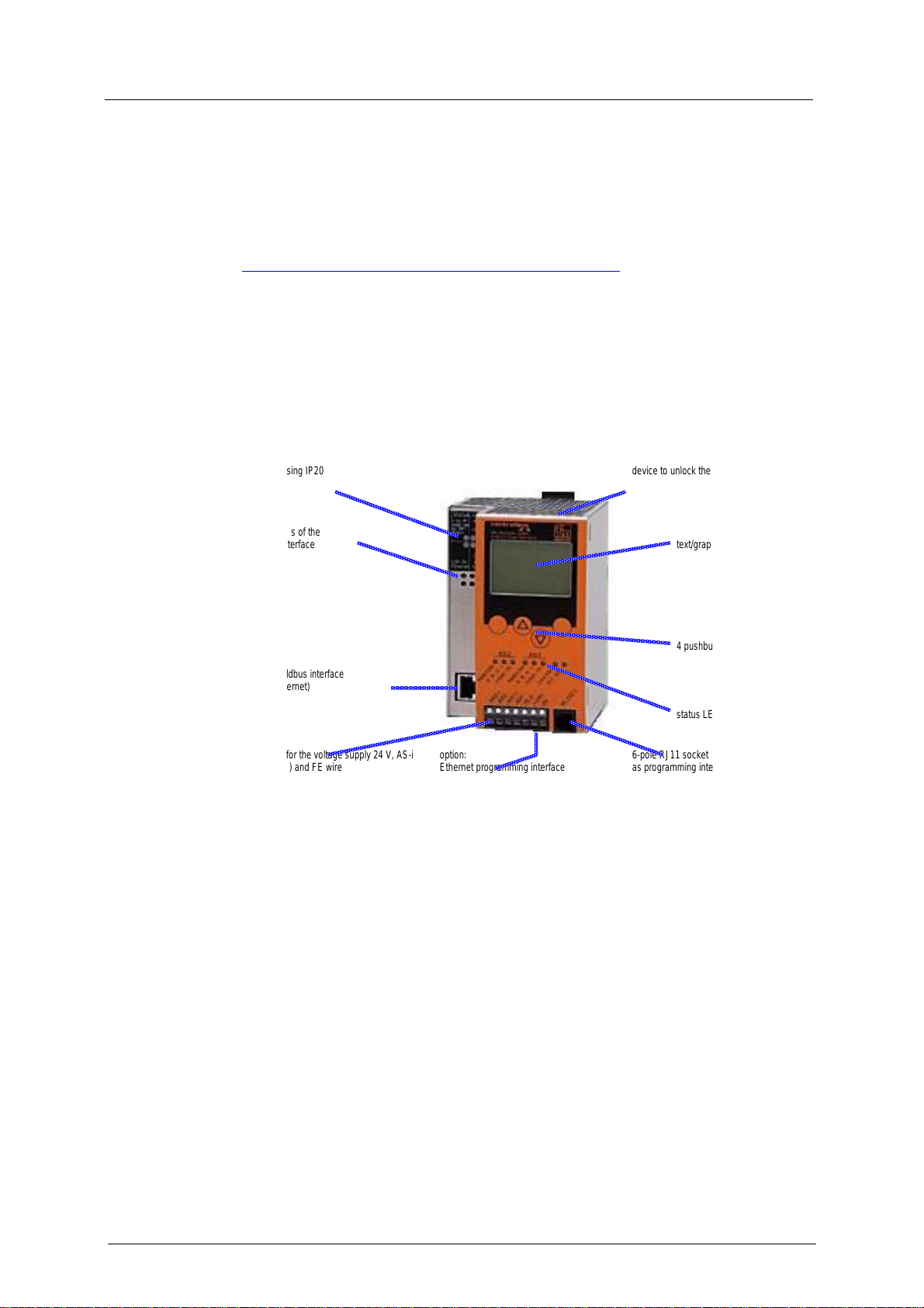
1.4 Overview: where is what?
metal housing IP20 device to unlock the unit from a rail
status LEDs of the
fieldbus interface
(option)
option: fieldbus interface
(here: Ethernet)
terminals for the voltage supply 24 V, AS-i
interface(s) and FE wire
photo: overview of controllere devices
option:
Ethernet programming interface
text/graphics display
4 pushbuttons
status LEDs
6-pole RJ11 socket of RS-232 C
as programming interface
1-3

Safety instructions
General
2 Safety instructions
In this chapter you can find general safety instructions such as
• general rules
• required previous knowledge
• safety instructions for mounting and installation
• When are you allowed to use this device and when not?
2.1 General
→ separate basic instructions of the device manual
No characteristics are warranted with the information, notes and examples
provided in this manual. The drawings, representations and examples imply no
responsibility for the system and no application-specific particularities.
The manufacturer of the machine/equipment is responsible for the safety of the
machine/equipment.
Danger
Property damage or bodily injury when the notes in this manual are not adhered to!
ifm electronic assumes no liability for this.
► The acting person must have read and understood the corresponding chapters
of this manual before performing any work on or with this device.
► The acting person must be authorised to work on the machine/equipment.
2.2 What previous knowledge is required?
This manual is intended for persons with knowledge of control technology and PLC
programming with IEC 61131-3 as well as the CoDeSys® software.
The manual is intended for persons authorised to mount, connect and set up the
controllere according to the EMC and low voltage directives. The controllers must
be installed and put into operation by a qualified electrician.
In case of malfunctions or uncertainties please contact the manufacturer: → back
of the manual.
2.3 Functions and features
→ basic instructions of the device manual
2-1


System requirements
Information concerning the device
3 System requirements
3.1 Information concerning the device
→ separate basic instructions of the device manual
3.2 Information concerning the software
→ separate basic instructions of the device manual
3.3 Required accessories
Basic functions → separate basic instructions of the device manual
For configuration and programming you also need:
• the software "CoDeSys for Automation Alliance™" version 2.3 or higher
(→ CD)
• In case of direct connection of the controllere to a PC with Ethernet interface
(LAN):
a cross-over CAT5 Ethernet patch cable with RJ45 plug on both sides:
2 m article no. EC2080
5 m article no. E30112
• In case of connection of the controllere to a PC with Ethernet interface (LAN)
via a hub or switch:
a common CAT5 Ethernet patch cable with RJ45 plug on both sides
• In case of direct connection of the controllere to a PC with serial interface:
programming cable article no. E70320
3-1


Getting started
4 Getting started
4.1
Connection ► Connect the functional earth
► Connect the yellow AS-i cable for every master
► Connect the 24 V supply
Set up the AS-i
master
Set up ProfibusDP
► Connect the Profibus cable to the fieldbus master
► Connect the addressed AS-i slaves to the yellow AS-i cable
► Power on
► If correctly addressed slaves are connected:
controllere menu: "Config All (→basic manual)
► If no slave is connected:
controllere menu "Easy Startup“ (→ basic manual)
► Controllere menu "Fieldbus Setup": set the Profibus address
(→ page
7-1, chapter "Set the parameters of the fieldbus interface in the
controllere")
► Copy the GSD file from the ifm CD (folder "gateway") to the suitable directory
of the corresponding fieldbus configuration program
► Define the I/O areas and the system behaviour in the fieldbus configuration
program
► Save the configuration
► Transfer the configuration to the DP-master
► Start the DP-master
4-1

Function
Data management
5 Function
Basic functions → separate basic instructions of the device manual
Ethernet programming interface → separate complementary device manual
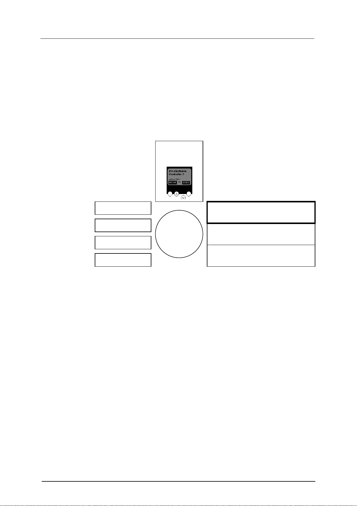
5.1 Data management
The controllere consists of different units:
text/graphics
display
AS-i master 1
fieldbus
interface
AS-i master 2
CPU
PLC
Ethernet
programming interface
SRAM memory
RS-232C
flash memory
programming interface
This manual exclusively describes the following subject:
• The optional fieldbus interface operates independently and exchanges data
with the central system via a "Dual port RAM" interface or a DMA transfer.
For the AS-i controllers with Profibus interface the Profibus-DP data management
is handled in the operating system (firmware) of the device. A special driver in the
PLC user program in the controllere is not required. In the mode Run/Stop the
digital and analogue output data is not transferred to the outputs of the AS-i slaves.
Therefore this data must be recopied in the PLC user program of the controller
.
e
More information concerning the addresses and assigment to the Profibus modules
is provided in → chapter
7 "Set-up".
5-1


Menu
Main menu "Quick Setup"
6 Menu
i
6.1 Main menu "Quick Setup"
Note
In this manual the menu text is always in English.
Basic functions → separate basic instructions of the device manual
Quick setting of the AS-i and fieldbus parameters, reading of the parameter data
(password level 1 required).
Details → page
Menu tree Explanation
8-62, chapter "Read fieldbus parameters"
Quick Setup
Fieldbus Setup
> Display of the current fieldbus address
► Change the fieldbus addresss using
the pushbuttons [▲] / [▼]
► After pressing [OK]:
> The controllere negotiates the quickest
baudrate with the fieldbus master
► Always after pressing [OK]:
> Display of the data saved in the
fieldbus master via the data packages
for communication with the AS-i
controllere:
• Digital inputs in the fieldbus master
from single or A-slaves on AS-i master
1
• Digital outputs in the fieldbus master to
single or A-slaves on AS-i master 1
• Digital inputs in the fieldbus master
from single or A-slaves on AS-i
master 2
• Digital outputs in the fieldbus master to
single or A-slaves on AS-i master 2
• Digital inputs in the fieldbus master
from B-slaves on AS-i master 1
• Digital outputs in the fieldbus master to
B-slaves on AS-i master 1
• Digital inputs in the fieldbus master
from B-slaves on AS-i master 2
• Digital outputs in the fieldbus master to
B-slaves on AS-i master 2
• Analogue multiplex inputs in the
fieldbus master
• Analogue multiplex outputs in the
fieldbus master
• Fieldbus data command channel
6-1

Menu
Main menu "Fieldbus Setup"
Menu tree Explanation
• Fieldbus data PLC inputs in the
fieldbus master
• Fieldbus data PLC outputs in the
fieldbus master
• Analogue inputs in the fieldbus master
from AS-i master 1
• Analogue outputs in the fieldbus
master to AS-i master 1
• Analogue inputs in the fieldbus master
from AS-i master 2
• Analogue outputs in the fieldbus
master to AS-i master 2
• Fieldbus data diagnosis
• Fieldbus master command channel
• Digital inputs in the fieldbus master
from single or A-slaves on AS-i master
1
(cycle starts again)
6.2 Main menu "Fieldbus Setup"
Setting of the fieldbus parameters, reading of the parameter data (password level 1
required).
Details → page
Menu tree Explanation
Fieldbus Set-up > Display of the current fieldbus address
8-62, chapter "Read fieldbus parameters"
► Cancel with [ESC]
► Change the fieldbus addresss using
the pushbuttons [▲] / [▼]
► After pressing [OK]:
> The controllere negotiates the quickest
baudrate with the fieldbus master
► Always after pressing [OK]:
> Display of the data saved in the
fieldbus master via the data packages
for communication with the AS-i
controllere:
• Digital inputs in the fieldbus master
from single or A-slaves on AS-i master
1
6-2
• Digital outputs in the fieldbus master to
single or A-slaves on AS-i master 1
• Digital inputs in the fieldbus master
from single or A slaves on AS-i
master 2
• Digital outputs in the fieldbus master to

Menu
Main menu "Fieldbus Setup"
Menu tree Explanation
single or A-slaves on AS-i master 2
• Digital inputs in the fieldbus master
from B-slaves on AS-i master 1
• Digital outputs in the fieldbus master to
B-slaves on AS-i master 1
• Digital inputs in the fieldbus master
from B-slaves on AS-i master 2
• Digital outputs in the fieldbus master to
B-slaves on AS-i master 2
• Analogue multiplex inputs in the
fieldbus master
• Analogue multiplex outputs in the
fieldbus master
• Fieldbus data command channel
• Fieldbus data PLC inputs in the
fieldbus master
• Fieldbus PLC outputs in the fieldbus
master
• Analogue inputs in the fieldbus master
from AS-i master 1
• Analogue outputs in the fieldbus
master to AS-i master 1
• Analogue inputs in the fieldbus master
from AS-i master 2
• Analogue outputs in the fieldbus
master to AS-i master 2
• Fieldbus data diagnosis
• Fieldbus master command channel
• Digital inputs in the fieldbus master
from single or A-slaves on AS-i master
1
(cycle starts again)
► Cancel with [ESC]
6-3

Set-up
Parameter setting of the controllere
7 Set-up
This chapter shows you how to get the Profibus interface started quickly.
7.1 Parameter setting of the controllere
Parameter setting of slaves in the controllere
Set the parameters of the slaves in the AS-i controllere as described in the basic
device manual.
Set the parameters of the fieldbus interface in the controllere
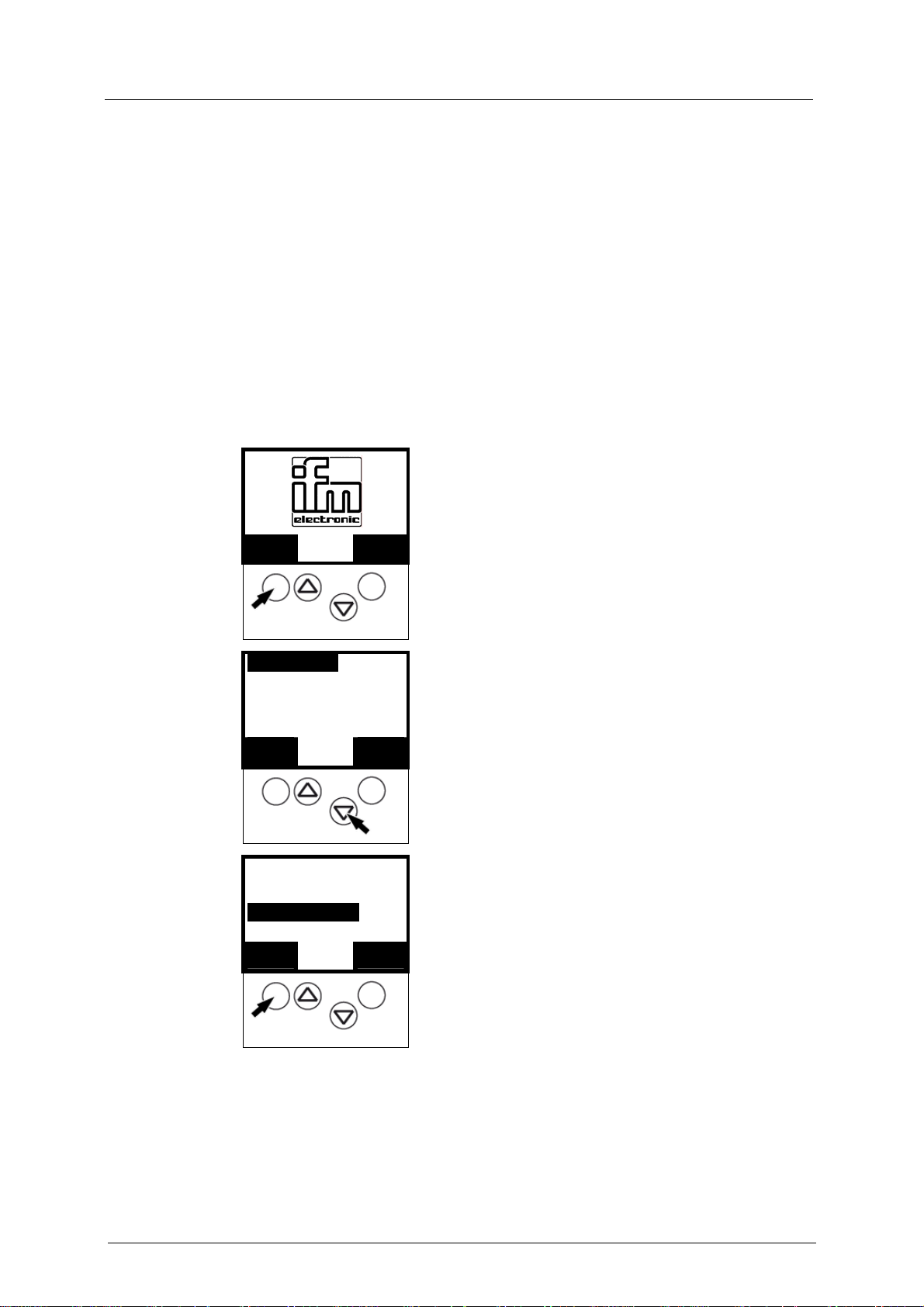
1.
MMEENNUU
Quick Setup
2.
PLC Setup
Slave lists
OOKK
Diagnostics
3.
Master setup
Fieldbus Setup
OOKK
0
1
▲ ▼
1
▲ ▼
UUSSEERR
EESSCC
EESSCC
► Press [ MENU ]
► Scroll to "Fieldbus Setup" with [▼]
► Select "Fieldbus Setup" with [OK].
7-1
Set-up
Connect the controllere to the Profibus host
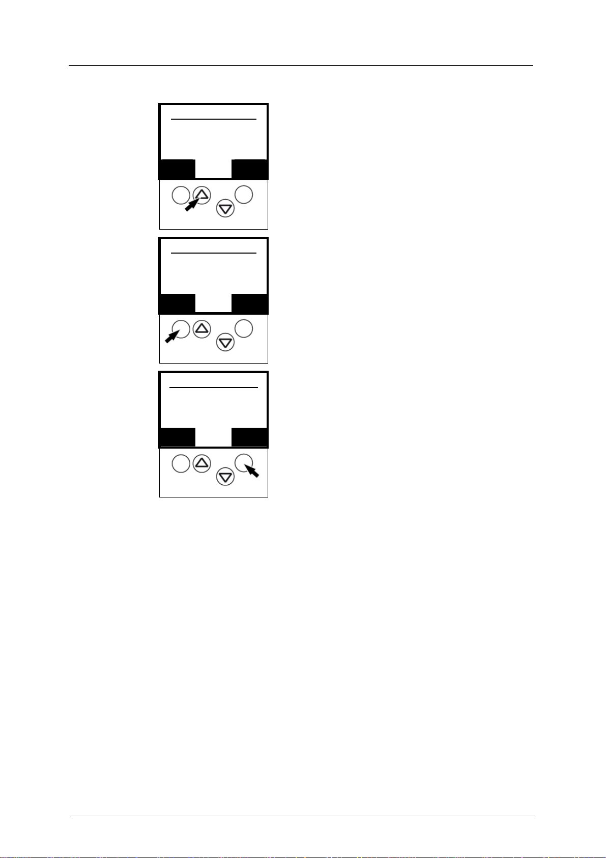
Fieldbus Address
4.
0
87
OOKK
▲ ▼
Fieldbus Address
5.
32
87
OOKK
▲ ▼
Fieldbus Baudrate
6.
#### KBaud
88
OOKK
▲ ▼
► Scroll to the requested address with [▲] / [▼].
EESSCC
► Save the fieldbus address with [OK].
EESSCC
> If there is communication with the fieldbus master:
display of negotiated baudrate
► Press OK to confirm.
> If there is no communication yet with the fieldbus
EESSCC
master: all possible baudrates move through the
display
► Cancel with [ESC].
7.2 Connect the controllere to the Profibus host
► Connect the Profibus cable to the controllere.
7.3 Parameter setting of the Profibus host
Device master file
→ Refer to the description of the Profibus interface on the host
(host = fieldbus master = in most cases higher-level PLC)
The GSD file on the ifm CD (e.g. ifm304D8.gsd) contains different possible
definitions (indications of length) for each of the 12 modules adapted to the
controllere.
→ Hardware catalogue of the Profibus configuration software in the folder
gateway.
► Copy this file to the suitable directory of the corresponding fieldbus
configuration program (→ its description).
7-2

Set-up
Parameter setting of the Profibus host
Programming software
The data of the controllere or the connected AS-i systems to be transferred can be
defined (by indicating the length of up to 12 modules) in the programming software
for the Profibus-DP master system (host).
You can select from these definitions for parameter setting in the host:
Example for module 1:
There is a choice of 5 entries:
• all single and A-slaves on AS-i
master 1
(length = 16 bytes)
• single and A-slaves with the
addresses 1(A)...23(A) on ASi master 1
(length = 12 bytes)
• single and A-slaves with the
addresses 1(A)...15(A) on ASi master 1
(length = 8 bytes)
• single and A-slaves with the
addresses 1(A)...7(A) on AS-i
master 1
(length = 4 bytes)
• no single or A-slaves on AS-i
master 1
(length = 0 byte)
If the parameters for a smaller number of slaves than indicated in the selection
point are to be set, you have created free reserve in the host.
Example: 5 single and/or A-slaves are connected to the AS-i master 1.
You have selected on the host:
"single and A-slaves with the addresses 1(A)...7(A) on AS-i master 1"
You have then created an address area reserve of 1 byte in the host which is not
used for the time being. The first 3 bytes of the reserved address area are used to
exchange data.
7-3

Set-up
Parameter setting of the Profibus host
Assign PLC addresses to the Profibus modules
What are "Profibus modules"? These are entries in a parameter setting database of
the programming software for the Profibus-DP master system (host). There you
assign the individual "modules" to the virtual "locations".
Locations are address areas for certain functions.
Modules are placeholders for certain addess quantities within these areas.
The following IEC addresses are the designations for the PLC addresses in the
controllere:
IEC address area
Description
from to
%IB1.1 %IB1.31 master1, slaves1A...31A, digital inputs
%IB2.1 %IB2.31 master2, slaves1A...31A, digital inputs
%IB11.1 %IB11.31 master1, slaves1B...31B, digital inputs
%IB12.1 %IB12.31 master2, slaves1B...31B, digital inputs
%IW21.1.x %IW21.31.x
%IW22.1.x %IW22.31.x
master1, slaves1...31,
analogue inputs x = channel *)
master2, slaves1...31,
Analogue inputs x = channel *)
%IW0.0 %IW0.63 DP-outputs for signal preprocessing
%IB0.128 %IB0.143
%IB0.144 %IB0.159
%IB0.160 %IB0.175
%IB0.176 %IB0.191
DP-outupts for master1, slaves1A...31A,
digital outputs
DP-outputs for master1, slaves1B...31B,
digital outputs
DP-outputs for master2, slaves1A...31A,
digital outputs
DP-outputs for master2, slaves1B...31B,
digital outputs
Data flow
AS-i – host
→
→
→
→
→
→
←
←
←
←
←
DP-
module
1 input
2 inputs
3 inputs
4 inputs
5 and 10
5 and 10
9
1 output
3 outputs
2 outputs
4 outputs
%IW0.96 %IW0.219
%IW0.224 %IW0.347
%IB0.704 %IB0.719
%IB0.720 %IB0.735
%IB0.736 %IB0.751
%IB0.752 %IB0.767
%QB1.1 %QB1.31
7-4
DP-outputs for master1, slaves1...31,
analogue outputs
DP-outputs for master2, slaves1...31,
analogue outputs
DP-parameters for master1,
slaves1A...31A, parameter data
DP-parameters for master1,
slaves1B...31B, parameter data
DP-parameters for master2,
slaves1A...31A, paramter data
DP-parameters for master2,
slaves1B...31B, parameter data
master1, slaves1A...31A,
←
←
←
←
←
←
→
11
11
DP-
parameter
s
DP-
parameter
s
DP-
parameter
s
DP-
parameter
s
–
Set-up
Parameter setting of the Profibus host
IEC address area
Description
from to
digital outputs
%QB2.1 %QB2.31
%QB11.1 %QB11.31
%QIB12.1 %QB12.31
%QW21.1.x %QW21.31.x
%QW22.1.x %QW22.31.x
master2, slaves1A...31A,
digital outputs
master1, slaves1B...31B,
digital outputs
master2, slaves1B...31B,
digital outputs
master1, slaves1...31,
analogue outputs x = channel *)
master2, slaves1...31,
analogue outputs x = channel *)
%QW0.0 %QW0.63 signal preprocessing outputs for DP-data
*) Channel numbers:
x = 0 → analogue channel 1
x = 1 → analogue channel 2
x = 2 → analogue channel 3
x = 3 → analogue channel 4
Data flow
AS-i – host
→
→
→
→
→
→
DP-
module
–
–
–
–
–
8
i
Tip
All outputs are reset in the PLC operating mode "Stop"!
Analogue outputs = 0
Digital outputs = FALSE
7-5
Set-up
Parameter setting of the Profibus host
Define Profibus-DP modules
The text of the different options of the modules always starts with the module
number (→ photo page
module list of the hardware catalogue starting with "1:" are options of the first
module in the device definition.
The first module for example defines the number of the binary I/O data bytes of
single or A slaves of AS-i master 1 in the controllere which are to be transferred to
the Profibus master via Profibus-DP.
i
Important!
The maximum data length of all 12 modules must not exceed 156 input bytes and
156 output bytes.
7-3, section "Programming software"). So all options in the
Example:
Siemens S7
For the advanced Profibus-DP user it is also possible to use length codes other
than those indicated as long as the maximum lengths of the modules are not
exceeded.
7-6
Set-up
Parameter setting of the Profibus host
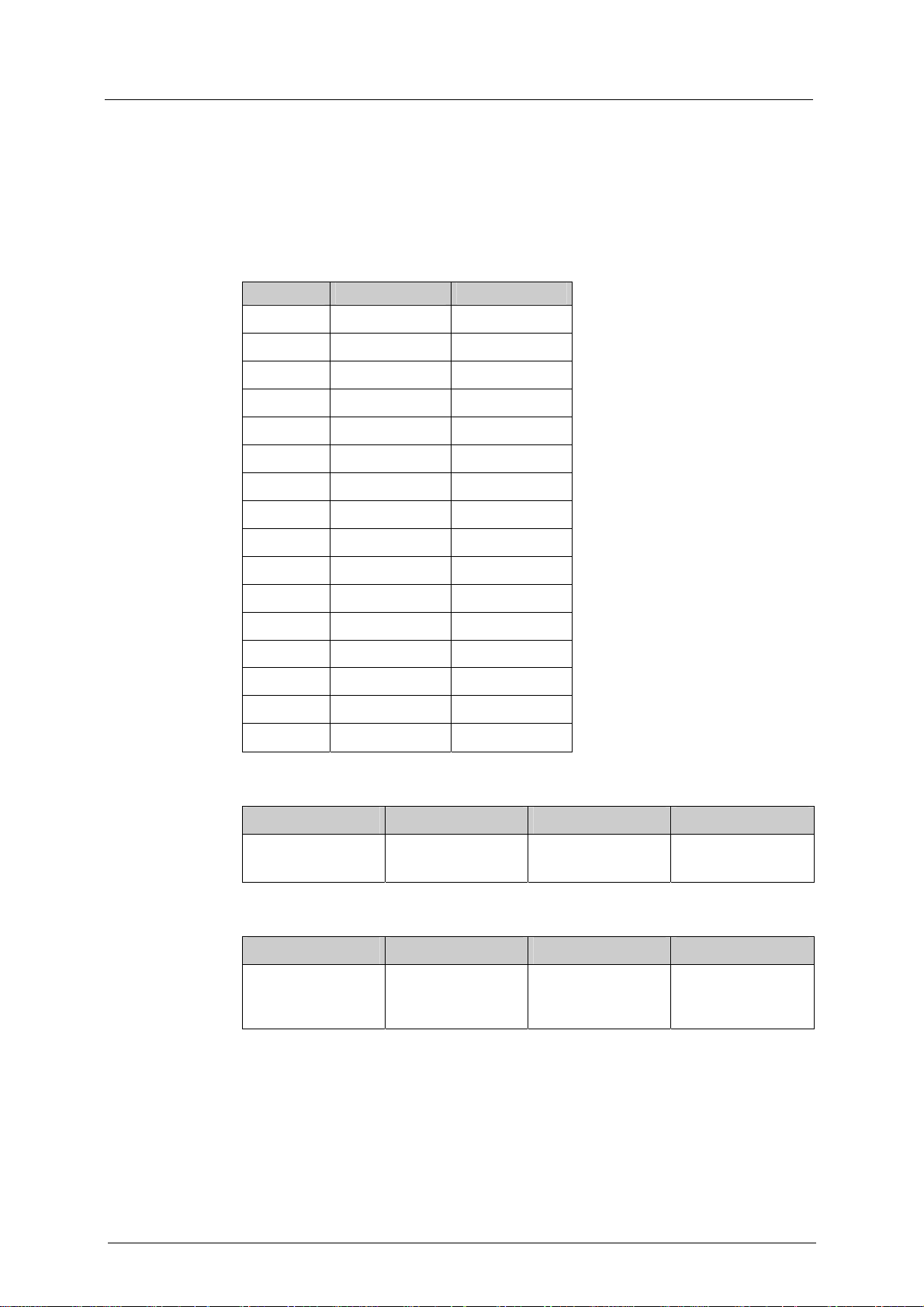
Module 1
Contents Binary inputs and outputs of single or A-slaves of AS-i master 1
Length 0...16-byte I/O (if not used: length = 0)
Byte no. Bits 4..7 Bits 0..3
1 flags master 1 slave1(A)
2 slave2(A) slave3(A)
3 slave4(A) slave5(A)
4 slave6(A) slave7(A)
5 slave8(A) slave9(A)
6 slave10(A) slave11(A)
7 slave12(A) slave13(A)
8 slave14(A) slave14(A)
9 slave16(A) slave15(A)
10 slave18(A) slave19(A)
11 slave20(A) slave21(A)
12 slave22(A) slave23(A)
13 slave24(A) slave25(A)
14 slave26(A) slave27(A)
15 slave28(A) slave29(A)
16 slave30(A) slave31(A)
The flags in the first input byte contain status information of the AS-i master 1:
Bit 7 Bit 6 Bit 5 Bit 4
PLC running in the
controllere
configuration error
in the AS-i system
no AS-i slave
detected
peripheral fault
The flags in the first output byte contain control information of the AS-i master 1:
Bit 7 Bit 6 Bit 5 Bit 4
reserved reserved reset of the stored
diagnostic data
activate transfer of
the stored
diagnostic data
If bit 4 of the control information is TRUE, the controllere transmits the stored
peripheral faults and configuration errors in the device-specific diagnosis. The flags
remain TRUE even if the fault or error is no longer present. Bit 5 in the control
information resets this information.
7-7

Set-up
Parameter setting of the Profibus host
Module 2
Contents Binary inputs and outputs of single or A-slaves of AS-i master 2
Length 0...16-byte I/O (if not used: length = 0)
Byte no. Bits 4..7 Bits 0..3
1 flags master 2 slave1(A)
2 slave2(A) slave3(A)
3 slave4(A) slave5(A)
4 slave6(A) slave7(A)
5 slave8(A) slave9(A)
6 slave10(A) slave11(A)
7 slave12(A) slave13(A)
8 slave14(A) slave14(A)
9 slave16(A) slave15(A)
10 slave18(A) slave19(A)
11 slave20(A) slave21(A)
12 slave22(A) slave23(A)
13 slave24(A) slave25(A)
14 slave26(A) slave27(A)
15 slave28(A) slave29(A)
16 slave30(A) slave31(A)
The flags in the first input byte contain status information of AS-i master 2:
Bit 7 Bit 6 Bit 5 Bit 4
PLC running in the
controllere
configuration error
in the AS-i system
no AS-i slave
detected
peripheral fault
The flags in the first output byte contain control information of the AS-i master 2:
Bit 7 Bit 6 Bit 5 Bit 4
reserved reserved reset of the stored
diagnostic data
activate transfer of
the stored
diagnostic data
If bit 4 of the control information is TRUE, the controllere transmits the stored
peripheral faults and configuration errors in the device-specific diagnosis. The flags
remain TRUE even if the fault or error is no longer present. Bit 5 in the control
information resets this information.
7-8
 Loading...