

Page 1
Device Manual
AS-i gateway Profibus DP
1 AS-i master 2 AS-i master
AC1335 AC1326
Smart Link DP AS-i DP Gateway
AS-i master profile: M3
Firmware: RTS 1.x
English
7390677_00_UK 2005-03-14
Page 2

device manual AS-i DP-Gateway
Important note!
When this manual was printed, it
considered the current state of
technology. It is intended for
technically trained persons. It was
prepared with utmost care.
The information, data and notes
provided in this manual represent no
warranted characteristics. No
guarantee is assumed for the absence
of mistakes, errors or the general
suitability of the indicated application
examples.
Drawings and representations depict
circuit examples and do not take into
account specifics of any given
application. Adherence to norms and
guidelines (i.e. installation of additional
fuses) is the responsibility of the
installer and user.
1-2
Page 3

device manual AS-i DP - Gateway
Contents device manual AS-i DP - Gateway:
1 About this manual ........................................................................................... 1-4
1.1 Important safety information!....................................................................................1-4
2 The AS-i DP-Gateway family........................................................................... 2-5
3 Mounting instructions..................................................................................... 3-6
4 Setting up the AS-i System............................................................................. 4-7
4.1 AS-i power supply ....................................................................................................4-7
4.2 AS-i diagnosis LEDs ................................................................................................4-9
4.3 Connecting the slaves..............................................................................................4-9
4.4 Display menu .........................................................................................................4-12
4.4.1 Menu structure..............................................................................................................4-14
5 Profibus DP configuration............................................................................ 5-15
5.1.1 Definition of the Profibus DP module............................................................................5-15
5.1.2 Device-specific Profibus DP parameters:.....................................................................5-28
5.1.3 AS-i diagnostics:...........................................................................................................5-29
6 Reference.......................................................................................................6-31
6.1 Display messages..................................................................................................6-31
6.1.1 AS-i system error (code E10 ... E30 )...........................................................................6-31
6.1.2 AS-i master command error (code M01 ... M20 ...........................................................6-33
6.1.3 Flash error (code F00 ... F10).......................................................................................6-35
6.1.4 Timeout error (code T00 ... T11)...................................................................................6-36
6.1.5 Boot error (code B00... B08).........................................................................................6-37
6.1.6 FAT error (code F01 ... F10).........................................................................................6-38
6.1.7 General RTS error (code R01 ... R30)..........................................................................6-39
6.1.8 Hardware error ( --- exception error --- ).......................................................................6-42
6.2 Technical data........................................................................................................6-43
1-3
Page 4
device manual AS-i DP-Gateway
1 About this manual
This manual describes the AS-i DP -Gateway family with AS-i version 2.1 master manufactured by ifm
electronic gmbh with two AS-i master (Ord.No. AC1326), as well as SmartLin k DP with one AS-i
master (Ord. No. AC1335).
To run the system you need in addition to the DP-Gateway a 24 V and an AS-i power supply as well
as single and/or A/B AS-i slaves. When using the two master unit (Ord.No. AC1326) it is necessary to
have a 24 V supply for power requirements as well as a second AS-i power supply and the
corresponding AS-i slaves for the second AS-i system.
1.1 Important safety information!
Specifications regarding the use of the AS-i DP -Gateway
The AS-i DP -Gateway contains one (AC1335) or two AS-i masters (AC1326), both according to
the AS-i version 2.1 and an Profibus DP fieldbus connection.
It controls the exchange of data to the sensor/actuator level,
communicates with the higher control level as fieldbus gateway.
Important directions on installation, connection and maintenance:
Ensure a condensation-free environment. Avoid excessive dust, vibration and shock. The
circulation of air through the vents must not be hampered.
Disconnect power. Connect the switching elements according to the terminal marking. Never
connect the minus potentials to each other or the minus potentials and the FE connection.
Ensure an electrically safe connection between the AS-i DP -Gateway (FE terminal) and
plant earth (functional ground).
1-4
Page 5
device manual AS-i DP - Gateway
2 The AS-i DP-Gateway family
The AS-i DP -Gateway contain 1 (AC1335) or 2 AS-i masters (AC1326) having the AS-i Association’s
advanced specification 2.1. This new specification brings the following features to the AS-i DP Gateway family:
a single slave can now be replaced with a pair of A/B slaves allowing connection of up to 62 (A/B)
slaves per master,
the new profiles S-7.3 and S-7.4 enable "plug and play" operation of analogue slaves
the introduction of periphery fault flags brings a better diagnosis of I/O modules in case of possible
erroneous connections
Detailed system diagnosis is made possible by the text/graphics-display of the DP-Gateway. The
operation of the four buttons can be learned intuitively. The two language capability of the text display
is especially useful for those who export their applications to a foreign. An intelligent message
management system generates priority controlled messages ensuring their display in orde r of
importance.
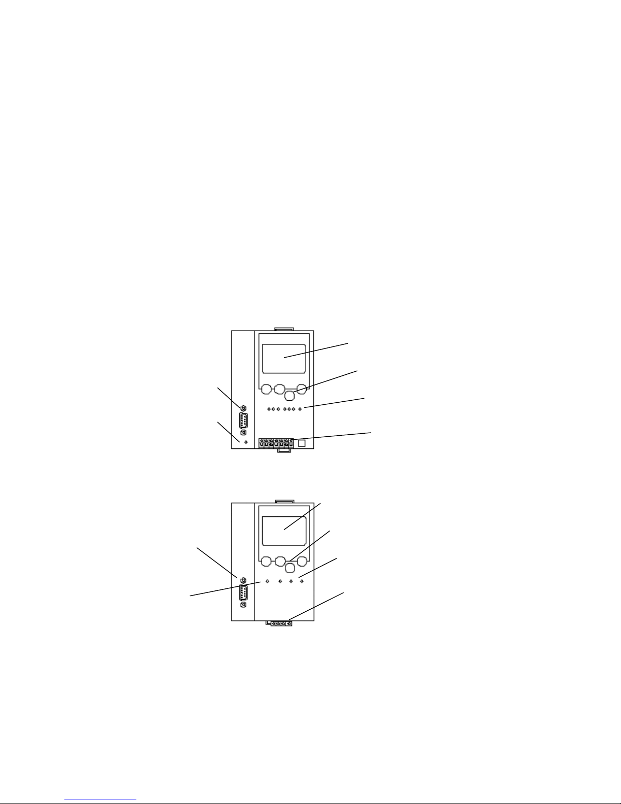
AC1326:
Displa
y
Buttons
Profibus DP Connection
Dia
g
nostic LEDs
Profibus DP LED
Terminals
AC1335:
Dis
play
Buttons
Profibus DP Connection
Dia
g
nostic LEDs
Terminals
Profibus DP
The se
rial programming interface of the AC1326 (RS232 C with RJ45 socket) can be used exclusively
to update device firmware.
The Field bus interface allows for the connection to a field bus system such as Profibus-DP thereby
facilitating operation as a very easy to use gateway.
2-5
Page 6
device manual AS-i DP-Gateway
3 Mounting instructions
A DIN rail (EN 50022) is to be used for mounting the AS-i DP -Gateway .It can be removed from the
DIN rail without any special tools.
The housing of the AS-i DP -Gateway is that of the modern 24V and AS-i power supplies made by ifm
electronic. The AS-i DP -Gateway having a height of only 107mm, just as the power supplies, fits
enclosures which have a height of 120mm.
Caution: The standard mounting position of the AS-i DP -Gateway is perpendicular in a
switching cabinet, which allows for optimum heat transfer from the unit. This
causes the temperature range of 0 to +60°C to be maintained when the spacing
allows good air flow.
The AS-i DP -Gateway should not be mounted directly near a frequency converter!
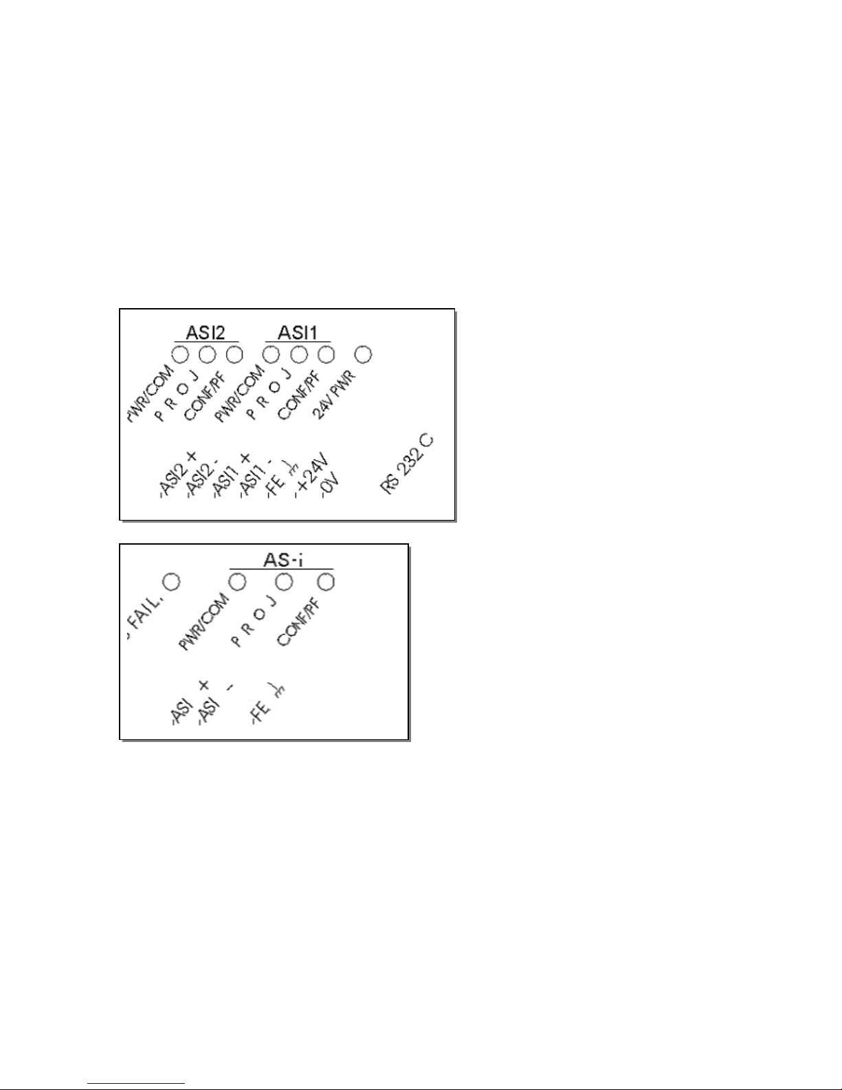
A 24 VDC (20..30V PELV) power supply, for example DN2011 from ifm electronic, is required for
operating the dual AS-i DP -Gateway AC1326. The connections are at terminals +24V and 0V (see
figure on next page).
Terminal FE is the functional ground (earth) of the unit!
Caution: Remove power from the power supply before connection of the AS-i DP -Gateway !
Note that the current consumption of the dual AS-i DP -Gateway AC1326 can reach 400 mA. The LED
'24V PWR‘ indicates the correct supply to the unit. The single master system AC1335 is completely
supplied with voltage from the AS-i system.
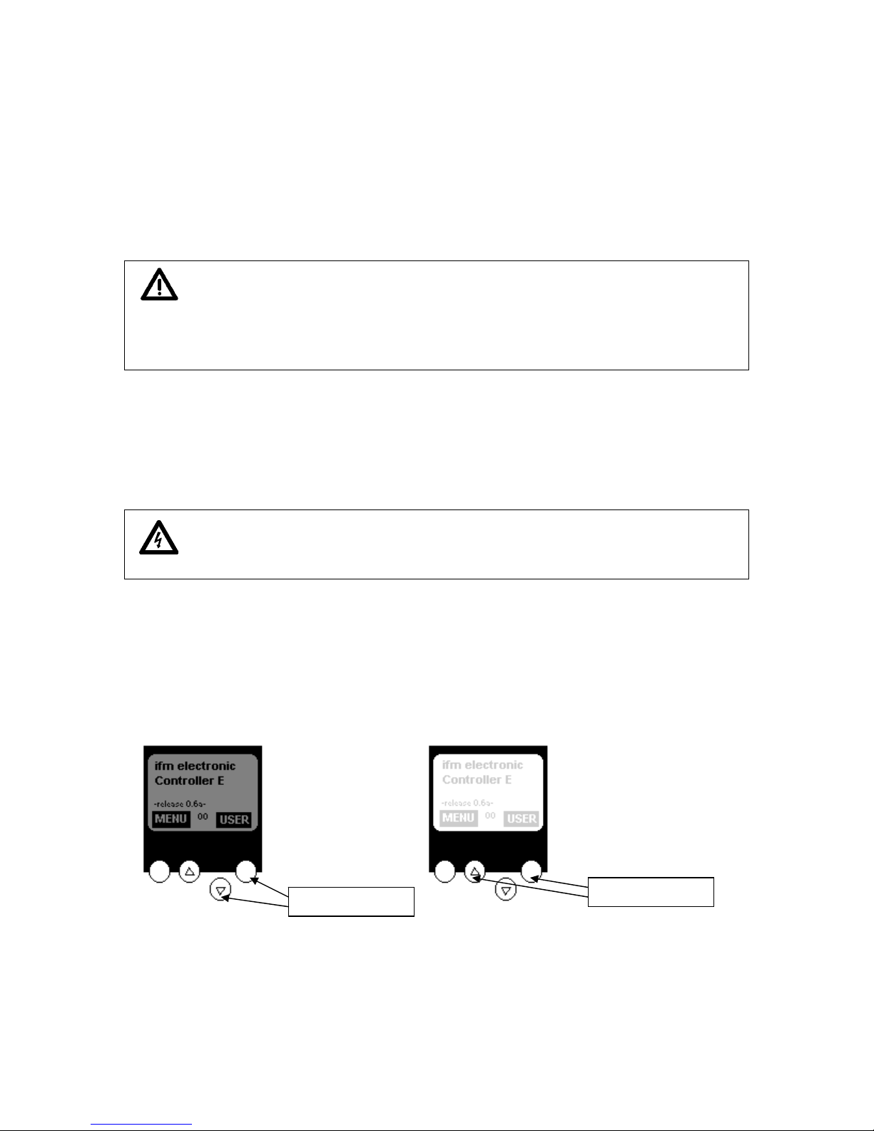
At power-up the text/graphic display indicates a start screen or possible error messages of the
connected AS-i systems.
If necessary the contrast of the display can be adjusted by pressing the right button and either the
button (lighter) or the button (darker) simultaneously as indicated in the figure below.
less contrast
more contrast
3-6
Page 7
device manual AS-i DP - Gateway
4 Setting up the AS-i System
4.1 AS-i power supply
A special AS-i power supply (for example AC1216) is required for operation of an AS-i system.
This power supply delivers the energy to the yellow AS-i cable and accomplishes the data decoupling
from the voltage regulator in the power supply. Standard switching power supplies would recognize
the AS-i data signals as a disturbance signal and would suppress them.
The AS-i + and AS-i – terminals are present twice on the AS-i power supply. This allows easy
connection to the AS-i 1+ and AS-i 1– terminals of AS-i DP -Gateway (or ASI 2+ and ASI 2- for the
second AS-i master system in AC1326). For the operation of a second AS-i master in AC1326 another
AS-i power supply is required causing the two systems to be galvanically separated. The AS-i masters
of AC1326 are partially supplied with voltage from the AS-i system. The single master system AC1335
is completely supplied with voltage from the AS-i system.
Caution: Most AS-i power supplies are short circuit protected. Nonetheless the power supply
should always be removed from voltage before the AS-i DP -Gateway is
connected.
Important: The AS-i system is to be operated without grounding. The AS-i + and AS-i – lines
are to be symmetrical to the plant earth. This is accomplished by making a low
resistance connection between the shield terminal and the plant earth.
4-7
Page 8

device manual AS-i DP-Gateway
AC1326 wiring example with only one AS-i system; Adherence to codes and guidelines (for
example addition of fuses) is the responsibility of the installer or user. The Profibus connection
required for proper operation is not shown.
AC1325 wiring example with only one AS-i system; Adherence to codes and guidelines (for
example addition of fuses) is the responsibility of the installer or user. The Profibus connection
required for proper operation is not shown.
4-8
Page 9
device manual AS-i DP - Gateway
4.2 AS-i diagnosis LEDs
The three diagnosis LEDs on the front of the AS-i DP -Gateway give information concerning the state
of the AS-i master and the connected AS-i system. The LEDs have the following meaning:
PWR/COM On: AS-i voltage ( Power) present and communication with at least one
slave has been established
Flashing: AS-i voltage ( Power) present but no slave communication established
P R O J On: Projection mode active, configuration monitoring not active
Flashing: Projection mode active, switch to protected mode not possible
because a slave having address 0 is connected
CONF / PF On: Projected and current configuration not the same
Flashing: Periphery fault on at least one of the connected slaves
4.3 Connecting the slaves
The AS-i units feature short-circuit and reverse polarity protection, nonetheless connections of for
example control cabinet modules should be made only after power has been turned off. Many slaves
of this type have a jumper which when connected causes the slave to be deactivated. Leave this
jumper connected at this point.
When using SmartLine modules please remove the combicon plug connected to AS-i +/-.
AS-i field modules usually consist of a lower part for connection of the yellow flat cable and an upper
part which contains the electronics. Place the yellow cable in the lower part but do not screw the upper
part on yet.
4-9
Page 10
device manual AS-i DP-Gateway
After the voltage ha
s been applied to both power supplies the AS-i DP -Gateway, the AS-i master and
AS-i cable are supplied with power. The green LED 'PWR/COM‘ flashes if only the AS-i power supply
and no slaves are connected to the system.
Now slaves are to be addressed. One method to do this is by means of the buttons and the
text/graphic display on the AS-i DP -Gateway. Choose the controller menu using the left button
('Menu') and select 'Slaves adr.‘ using the button. Confirm this choice using the left button ('OK‘)
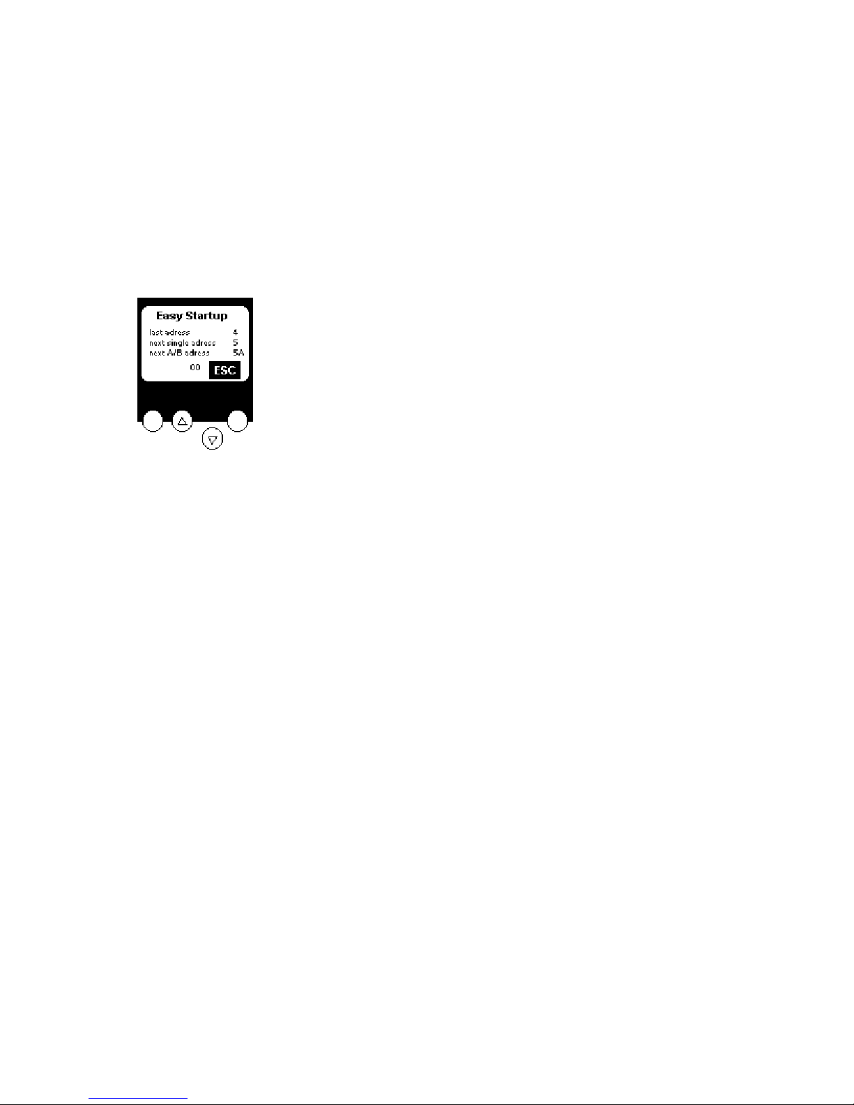
and then choose ‚Easy Startup‘.
The AS-i slave address is non-volatilely stored in every slave. To allow the AS-i master to individually
communicate with each slave the slave must have a unique address in the system.The manufacturer
delivers each AS-i slave with the address 0. When the AS-i DP -Gateway runs in the Easy Startup
Mode, slaves are addressed automatically in increasing order.
Choose the desired master and confirm with 'OK‘. The AS-i DP -Gateway assigns the lowe st free
address to the next slave which is connected and has the address 0.
Try this by connecting a new slave. The LED ‘PWR/COM‘ stops flashing since at least one slave has
been detected correctly. The red lighting LED 'CONF/PF’ is still correct at this stage of system set-up.
It indicates that the new slave has not been projected in the master yet. The text/graphic display of the
AS-i DP -Gateway gives information as to the slave addresses which have already been assigned as
well as the status of the system set-up.
This automatic procedure can only function if each newly connected slave has the address 0! If the
slaves have already been used in another system they probably have an address which is not 0. In
this case the AS-i DP -Gateway does not react as expected. Remove the slave from the system and
readdress it to 0 using one of the methods discussed below.
Terminate the addressing procedure by pressing the 'ESC‘ button several times until the main menu
is active and choose ‘QuickSetup‘.
The next option in QuickSetup is 'Config all‘. Choose the desired master to which the slave is to be
connected and confirm this choice. The red LED 'CONF/PF‘ and the orange LED 'PROJ‘ should now
go out. The system configuration is now complete.
If incorrectly addressed slaves remain, they can be addressed as follows: Remove all slaves except
that slave which is to be readdressed.
4-10
Page 11
device manual AS-i DP - Gateway
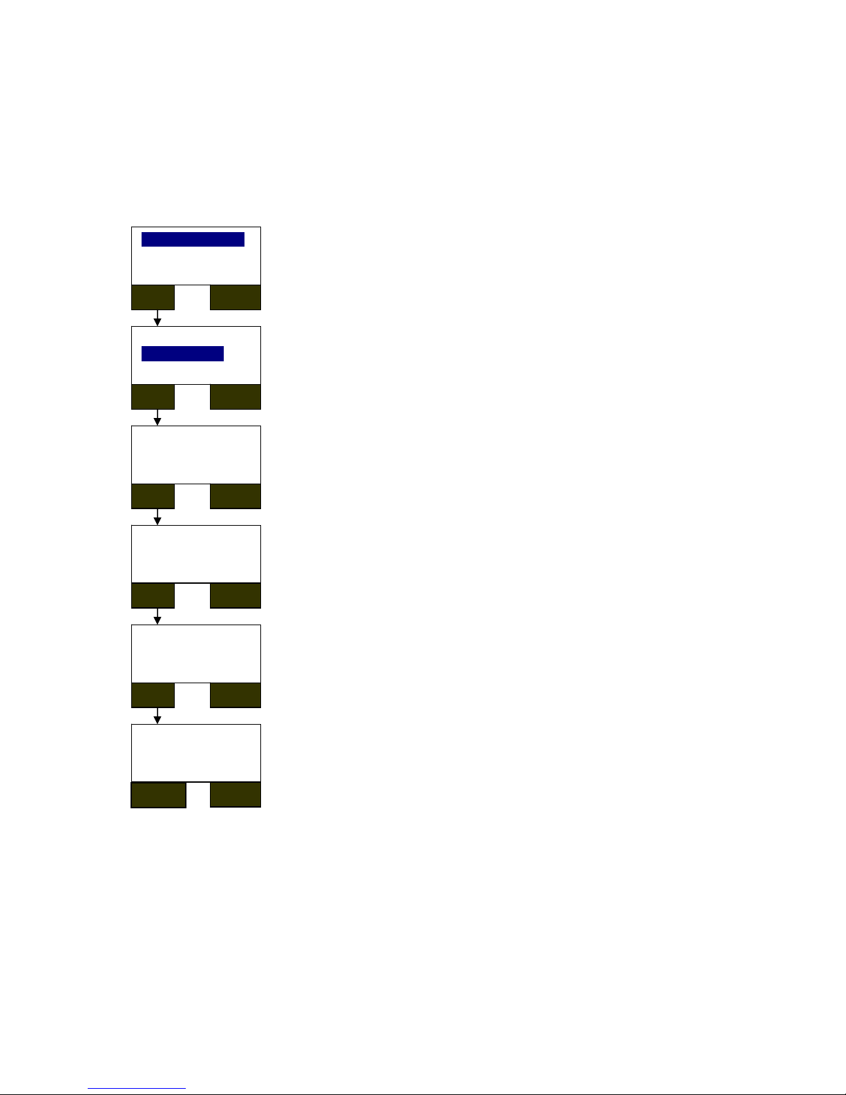
Choose the op
tion "Change Address" and the desired AS-i master in the menu "Address Slave".
The first slave which is detected (i.e. the slave with the lowest address) is displayed. Since in this case
only one slave is connected the indicated address can only be that of this slave. Pressing the ‘OK‘
button causes the first free slave address to be displayed (generally the address 0.) The desired new
address can be chosen using the arrow buttons. The confirmation is initiated with the ‘OK‘ button,
after which the selected addresses are redisplayed. If this address is not correct, the addressing
procedure can be terminated with ‘ESC‘. If the address is the one desired, press ‘OK’ and the
addressing process will be completed.
Change Address
Easy Startup
OK ESC
Addr. Slave of
AS-i Master 1
AS-i Master 2
OK ESC
Curr. Slave Addr.
AS-i Master 1
5
OK ESC
New Slave Addr.
AS-i Master 1
0
OK ESC
Change Address
Master 1
Cur. Slave Addr. 5
OK ESC
Addressing done
Master 1
Cur. Slave Addr. 5
NEXT
ESC
4-11
Page 12
device manual AS-i DP-Gateway
4.4 Display menu
The four buttons of the AS-i DP -Gateway enable simple and fast working with the menu presentation
in the display.
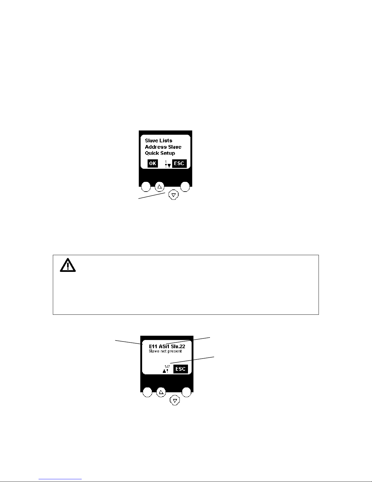
The and buttons are used to select the menu or change the displayed values. Menus with more
than three options are adapted automatically. If the menu can be selected upwards or downwards, a
triangle is displayed in the middle.
If both arrow buttons are pressed simultaneously, the displayed menu switches between German and
English texts.
Both keys
simultaneously:
GermanEnglish
The two oute
r keys are function keys, that is their meaning is displayed in the bottom line of the
display by two inverted texts.
Important: The password option contained in the menu point System-Setup can be used to
enable or restrict menu operation. The unit is in the user–mode when delivered.
Entering a non-valid password (such as 1000) deactivates all menu points with
which settings may be changed. Entering the password 'CE01' activates
(reactivates) the user- mode. The password is stored in a non-volatile memory be
means of the menu point System-Setup /Save System.
ASI1: AS-i master 1
Slv22: AS-i slave 22
E11: error code
1/7: first of 7 messages
The mo
st important messages have a higher display priority, it is however possible to scroll through
the list by pressing the arrow keys. All possible AS-i error messages are listed in the annex.
4-12
Page 13

device manual AS-i DP - Gateway
System errors pertai
ning to AS-i DP -Gateway are displayed in a different way. They are immediately
displayed when they occur and must be confirmed by pressing the right key. All possible system error
messages are listed in the annex.
F10: system error number
4-13
Page 14

device manual AS-i DP-Gateway
4.4.1 Menu structure
Start display (AS-i Error Diagnostic)
press ‚Menu‘ button
Slave Lists: check the addresses of connected AS-i slaves
- See list of detected AS-i slaves (LDS)
- See list of projected AS-i slaves (LPS)
- See list of activated AS-i slaves (LAS)
- See list of periphery faults on AS-i slaves (LPF)
Slave addresses: programming of the addresses of the connected AS-i slaves
- Readdress AS-i slaves connected to AS-i DP -Gateway
- Address new AS-i slaves to the next free address automatically (Easy Startup)
Quick Setup: everything needed for basic configuration
- Teach in the current AS-i configuration (Config all)
- Setup the field bus connection
System Setup: setup the AS-i DP -Gateway device
- Save current system settings
- Setup the baud rate of the serial programming port (AC1326 only)
- Update the firmware of the AS-i DP -Gateway (requires special software)
System Info: device information
- See the hardware and firmware version numbers of this AS-i DP -Gateway
- See the serial number of this AS-i DP –Gateway
Diagnostics: Information for System Diagnostics (AC1335 only)
- Read the configuration error counter of the connected AS-i system
- Read the telegram error rate of the connected AS-i system
- Reset the configuration error counter
- Display transmission errors to the connected AS-i system
Master Setup: information on AS-i master system
- Teach in the current AS-i configuration (Config all)
- Change to projecting mode: Configure the AS-i system
- Change to protected mode: normal operation (master checks configuration)
- Enable automatic AS-i slave addressing in protected mode
- Disable AS-i reset when activating protected mode
- See the counter of config errors in the connected AS-i systems (AC1326)
- Reset the counter of config errors (AC1326)
- See the rating of faulty AS-i telegrams in the connected AS-i systems (AC1326)
Slave Setup: detailed information about the connected AS-i slave
- See the digital or analogue I/Os of the connected AS-i slaves
- See the parameters of the connected AS-i slaves
- See the I/O and ID codes of the connected AS-i slaves
- See the telegram errors related to the connected AS-i slaves
Field bus Setup: the different field bus interfaces are optional
- Setup the node address of the AS-i DP -Gateway in the high level field bus
- Setup other settings if neccessary in the used high level field bus
4-14
Page 15

device manual AS-i DP - Gateway
5 Profibus DP configuration
The AS-i DP -Gateway AC1325/AC1326 is a modular Profibus DP slave. To set up the Profibus DP
slave address select the menu "field bus setup" in the AS-i DP -Gateway display. The new address is
stored non volatilely in the device.
Profibus DP- Gateway with 2 AS-i Master (AC1326)
SmartLink DP with 1 AS-i Master (AC1335)
In the programming software for the Profibus DP master system the data to be transferred to the AS-i
DP -Gateway or the connected AS-i systems can be defined by indicating the length of up to 12
modules.
The GSD file ifm_04D8.gsd for AC1326 contains different possible definitions (indicated lengths) for
each of the 11 modules, the file ifm_07E5.gsd for AC1335 contains different possible definitions for
12 modules. You can find the GSD file in the hardware catalogue of the Profibus configuration
software in the folder Gateway.
The double master AC1326 uses the GSD of the controllere family which is listed in the hardware
catalogue as "ASI-DP-Controller e" and supports 11 modules. The single master AC1335 is indicated
in the hardware catalogue as "ASI-DP-Gateway" and supports an additional module 12 if using GSD
revision 2 and device firmware version 1.23 or higher.
5.1.1 Definition of the Profibus DP module
The texts of the different options of the modules always start with the module number. All options in
the module list of the hardware catalogue starting with 1: are thus options of the first module in the
device definition.
5-15
Page 16

device manual AS-i DP-Gateway
The first mo
dule for example defines the number of binary I/O data bytes of single or A slaves of AS-i
master 1 in the AS-i DP -Gateway which are to be transferred to the Profibus master via Profibus DP.
The maximum data length of all 11 modules must not exceed 156 input bytes and 156 output bytes.
For the advanced Profibus DP user it is also possible to use other length codes than those given as
long as the respective maximum lengths of the modules are not exceeded.
When using the single master AC1325, modules which refer to master 2 are to be configured using
spaces as placeholders.
Configuration example AC1335
Configuration example AC1326
Module1:
Content: binary inputs and outputs of Single- or A-slaves of AS-i master 1
Length: 0..16 Byte I/O (=0 if not used)
Byte No. Bits 4..7 Bits 0..3
1 flags master 1 Slave1(a)
2 Slave2(a) Slave3(a)
..
15 Slave28(a) Slave29(a)
16 Slave30(a) Slave31(a)
5-16
Page 17

device manual AS-i DP - Gateway
The AS-i ma
ster status information in the first byte of the digital inputs of the single /A slave data (byte
0, bit 4..7) contains the master flags of the respective AS-i system:
Bit7 Bit6 Bit5 Bit4
reserved configuration error in
AS-i system
no AS-i slave detected periphery fault
The AS-i master control information in the first byte of the digital outputs of the single/A slave data
(byte 0, bit 4..7) controls the stored diagnostic information:
bit7 bit6 bit5 bit4
reserved reserved reset the stored diagnostic
data
activate transfer of the stored
diagnostic data
If bit 4 of the control information is TRUE, the AS-i DP -Gateway transmits the stored periphery and
configuration error in the device-specific diagnostics. The flags remain TRUE even if the error is no
longer present. Bit 5 in the control information resets this information.
More information on this subject is to be found in the paragraph "AS-i diagnostics".
Module 2:
Content: Only AC1326: binary inputs and outputs of Single- or A-slaves of AS-i master 2
Length: 0..16 Byte I/O (=0 if not used)
Byte No. Bits 4..7 Bits 0..3
1 flags master 2 Slave1 (a)
2 Slave2 (a) Slave3 (a)
..
15 Slave28 (a) Slave29 (a)
16 Slave30 (a) Slave31 (a)
The flags in the first input byte contain status information, the flags in the first output byte contain
control information refering to AS-i master 2. (For more about this subject see module 1.)
Module 3:
Content: binary inputs and outputs of B-slaves of AS-i master 1
Length: 0..16 Byte I/O (=0 if not used)
Byte No. Bits 4..7 Bits 0..3
1 flags master 1 Slave1b
2 Slave2b Slave3b
..
15 Slave28b Slave29b
16 Slave30b Slave31b
The flags in the first input byte contain status information, the flags in the first output byte contain
control information refering to AS-i master 1. (For more about this subject see module 1.)
5-17
Page 18

device manual AS-i DP-Gateway
Module 4:
Content: Only AC1326: binary inputs and outputs of B-slaves of AS-i master 2
Length: 0..16 Byte I/O (=0 if not used)
Byte No. Bits 4..7 Bits 0..3
1 flags master 2 Slave1b
2 Slave2b Slave3b
..
15 Slave28b Slave29b
16 Slave30b Slave31b
The flags in the first input byte contain status information, the flags in the first output byte contain
control information refering to AS-i master 2. (For more about this subject see module 1.)
Module 5:
Content: multiplexed analogue inputs of AS-i master 1 and 2
Length: 2 word consistent I/O (=0 if not used)
DP master request:
1st word: MMXSSSSS 000000CC
Bit:
15 14 13 12 11 10 9 8 7 6 5 4 3 2 1 0
MM X SSSSS 0 0 0 0 0 0 CC
MM:= 2 bit master number 1..2;
X:= 0=A/Single, 1=B-Slave;
SSSSS:= 5 bit slave number 1..31
CC:= 2 bit channel No. 0..3
to calculate: (slave No.) + (master No. * 64) + (32 if B-Slave)
2nd word: not used
AS-i DP -Gateway response:
1st word: MMXSSSSS EEEE00CC (copy of request)
EEEE:= 4 bit error No. of response: 0=OK, 1=not valid,
2=Overflow, 4=no active analogue slave.
2nd word: analogue value, INTEGER
5-18
Page 19

device manual AS-i DP - Gateway
Module 6:
Note: If the analogue outputs are also driven by module 10 the output values of module 6 are
overwritten by the values of module 10.
Content: multiplexed analogue outputs of AS-i master 1 and 2
Length: 2 word consistent I/O (=0 if not used)
DP master request:
1st word: MMXSSSSS 000000CC
MM:= 2 bit master number 1..2;
X:= 0=A/Single, 1=B-Slave;
SSSSS:= 5 bit slave number 1..31
CC:= 2 bit channel No. 0..3
to calculate: (slave No.) + (master No. * 64) + (32 if B-Slave)
2nd word: analogue value, INTEGER
AS-i DP -Gateway response:
1st word: MMXSSSSS EEEE00CC (copy of request)
EEEE:= 4 bit error No. of response: 0=OK, 1= invalid,
2=Overflow, 4=no active analogue slave.
2nd word: analogue value, INTEGER (copy of request)
Module 7:
Content: command channel
Length: 4 byte consistent I/O (=0 if not used)
DP master request:
1st byte command No.
2nd byte: MMXSSSSS (as far as necessary; see table below)
MM:= 2 bit master number 1..2;
X:= 0=A/Single, 1=B-Slave;
SSSSS:= 5 bit slave number 1..31
to calculate: (slave No.) + (master No. * 64) + (32 if B-Slave)
3rd to 4th byte: data; see table below
AS-i DP -Gateway response:
1st byte command No. (copy of request)
2st byte: MMXSSSSS (copy of request)
3rd to 4th byte: data; see table below
5-19
Page 20

device manual AS-i DP-Gateway
Comm
and
no.
Description Byte 2 Byte 3 Byte 4
1 Get master flags MM000000 0 answer: MM000000 master flags
2 Set operating mode MM000000 0 = Protected mode
1 = Config mode
-
answer: MM000000 0 = Protected mode
1 = Config mode
-
3 Get curr.slave config MMXSSSSS - answer: MMXSSSSS act. CDI
4 Get proj. slave conf. MMXSSSSS - answer: MMXSSSSS proj. CDI
5 Proj. slave config MMXSSSSS proj. CDI
answer: MMXSSSSS proj. CDI
6 Get slave param. MMXSSSSS - answer: MMXSSSSS proj. parameter act. parameter
7 Proj. slave param. MMXSSSSS proj. parameter answer: MMXSSSSS proj. parameter 8 Get LAS MMXSSSSS - answer: MMXSSSSS LAS 0..15 or 16..31 or 0..15b or 16b..31b
9 Get LDS MMXSSSSS - answer: MMXSSSSS LDS 0..15 or 16..31 or 0..15b or 16b..31b
10 Get LPF MMXSSSSS - answer: MMXSSSSS LPF 0..15 or 16..31 or 0..15b or 16b..31b
11 Get LPS MMXSSSSS - answer: MMXSSSSS LPS 0..15 or 16..31 or 0..15b or 16b..31b
12 reserved - 13 Get err. counter MMXSSSSS - answer: MMXSSSSS Error counter
14 Get conf. err. cntr MM000000 - answer: MM000000 Error counter
15 Get ASi cycle cntr MM000000 - answer: MM000000 Error counter
16 Set slave param. MMXSSSSS parameter answer: MMXSSSSS reflected parameters 17,18 reserved - - 19 Config all MM000000 - answer: MM000000 State 20 reserved - - 21 Store configu ration into flash MM000000 - answer: MM000000 State 22 Reset err. counter MMXSSSSS - answer: MMXSSSSS Error counter
23 Address slave MMXSSSSS 00XSSSSS answer: MMXSSSSS - 62 Continuous Command mode
0 0 = Read mode
1 = Change mode
0 = Deactivated
1 = Activated
answer: 0 0 = Read mode
1 = Change mode
0 = Deactivated
1 = Activated
63 Null comman d without function - - answer: - - -
5-20
Page 21

device manual AS-i DP - Gateway
Note: Two bits of the Command response byte indicate the state of the command channel:
D7 = 1 -> Error during command processing
D7 = 0 -> No error
D6 = 1 -> Command being processed,channel busy.
D6 = 0 -> Command processed,response buffer valid.
The commands are normally executed only if the command byte (first byte) is changed! For
continuous execution of the same command please switch into 'Continuous command mode' first! This
can be done with command No. 62.
Examples (Values given in hexadecimal form)
Example command 1, read master flags:
DP Master Request:
1. Byte: 16#01 (command number)
2. Byte: 16#40 (AS-i Master 1)
3. Byte: 16#00 (not used)
4. Byte: 16#00 (not used)
DP- Gateway Response:
1. Byte: 16#01 (copy of request)
2. Byte: 16#40 (copy of request)
3.-4. Byte: Data ; see table below
Master-Flags:
Byte Bit Meaning of Bit = TRUE
3 0 the periphery of connected AS-i slaves is OK ( no Peripheral Fault)
3 1 the automatic addressing is enabled
3 2 the data transfer to at least 1 slave is active
3 3..7 reserved
4 0 the AS-i configuration is OK
4 1 one Slave 0 detected
4 2 the automatic addressing is enabled
4 3 the automatic addressing is active
4 4 the config mode is active
4 5 the normal operation is active
4 6 an AS-i voltage error has occured
4 7 the offline phase is active
Example Command 2, change operation mode
DP Master Request:
1. Byte: 16#02 (command number)
2. Byte: 16#40 (AS-i Master 1)
3. Byte: 16#01 (config mode)
4. Byte: 16#00 (not used)
DP-Gateway Response:
1. Byte: 16#02 (copy of request)
2. Byte: 16#40 (copy of request)
3. Byte: 16#01 (config mode now active)
4. Byte: 16#00 (not used)
5-21
Page 22

device manual AS-i DP-Gateway
Example co
mmand 3: read current slave configuration:
DP Master Request:
1. Byte: 16#03 (command number)
2. Byte: 16#47 (AS-i Master 1, Slave Nr. 7) (AS-i master 1, slave no. 7)
3. Byte: 16#00 (not used)
4. Byte: 16#00 (not used)
DP-Gateway Response:
1. Byte: 16#03 (copy of request)
2. Byte: 16#47 (Copy of request)
3. Byte: 16#EF (extended ID Code 2 = 16#E, extended ID Code 1 = 16#F)
4. Byte: 16#03 (ID Code = 16#0, IO-Configuration = 16#3)
(corresponds to slave profile S 3.0.E, 2I/2O module with periphery error detection)
Example command 4: read projected slave configuration:
DP Master Request:
1. Byte: 16#04 (command number)
2. Byte: 16#50 (AS-i Master 1, Slave Nr. 16) (AS-i master 1, slave no. 16)
3. Byte: 16#00 (not used)
4. Byte: 16#00 (not used)
DP-Gateway Response:
1. Byte: 16#04 (copy of request)
2. Byte: 16#50 (Copy of request)
3. Byte: 16#EF (extended ID Code 2 = 16#E, extended ID Code 1 = 16#F)
4. Byte: 16#37 (ID Code = 16#3, IO-Konfiguration = 16#7)
(corresponds to slave profile S 7.3.E, 4I analogue-module)
Example command 5: project slave configuration:
DP Master Request:
1. Byte: 16#05 (command number)
2. Byte: 16#81 (AS-i master 2, slave no. 1)
3. Byte: 16#6F (extended ID Code 2 = 16#6, extended ID Code 1 = 16#F)
4. Byte: 16#37 (ID Code = 16#3, IO- configuration = 16#7)
(corresponds to slave profile S 7.3.6, 4O analogue-module)
DP-Gateway Response:
1. Byte: 16#05 (copy of request)
2. Byte: 16#81 (Copy of request)
3. Byte: 16#6F (Copy of request)
4. Byte: 16#37 (Copy of request)
Example command 6, read slave parameters:
DP Master Request:
1. Byte: 16#06 (command number)
2. Byte: 16#42 (AS-i master 1, slave no. 2)
3. Byte: 16#00 (not used)
4. Byte: 16#00 (not used)
DP-Gateway Response:
1. Byte: 16#06 (Copy of request)
2. Byte: 16#42 (Copy of request)
3. Byte: 16#03 (projected parameters = 16#3)
4. Byte: 16#0F (current parameters = 16#F)
5-22
Page 23

device manual AS-i DP - Gateway
Example co
mmand 7, project slave parameters:
Note: The projected parameters can only be changed if the AS-i master is in config mode! Please
refer to command 2.
DP Master Request:
1. Byte: 16#07 (command number)
2. Byte: 16#42 (AS-i Master 1, Slave Nr. 2)
3. Byte: 16#0F (set projected parameters to 16#F)
4. Byte: 16#00 (not used)
DP-Gateway Response:
1. Byte: 16#07 (Copy of request)
2. Byte: 16#42 (Copy of request)
3. Byte: 16#0F (Copy of request)
4. Byte: 16#00 (not used)
Example command 8, read LAS(List of Active Slaves:
DP Master Request:
1. Byte: 16#08 (command number)
2. Byte: 16#42 (AS-i master 1, slave no. 2, corresponds to slaves 1...15 = group 1)
3. Byte: 16#00 (not used)
4. Byte: 16#00 (not used)
DP-Gateway Response:
1. Byte: 16#08 (Copy of request)
2. Byte: 16#42 (Copy of request)
3. Byte: 16#02 (slaves 8..15, that means slave 9 is activated)
4. Byte: 16#04 (slaves 1..7, that means slave 2 is activated)
The answer returns the slave list to which the requested slave belongs.
Group
Slave
Byte 3 Byte 4
1
15a 14a 13a 12a 11a 10a 9a 8a 7a 6a 5a 4a 3a 2a 1a 0 *
2
31a 30a 29a 28a 27a 26a 25a 24a 23a 22a 21a 20a 19a 18a 17a 16a
3
15b 14b 13b 12b 11b 10b 9b 8b 7b 6b 5b 4b 3b 2b 1b res
4
31b 30b 29b 28b 27b 26b 25b 24b 23b 22b 21b 20b 19b 18b 17b 16b
(*) -> LAS and LPS do not contain slave 0, therefore these values are set to 0 by default.
Example command 9, read LDS(List of Detected Slaves):
DP Master Request:
1. Byte: 16#09 (command number)
2. Byte: 16#50 (AS-i master 1, slave no. 16, corresponds to slaves 16...31 = group 2)
3. Byte: 16#00 (not used)
4. Byte: 16#00 (not used)
DP-Gateway Response:
1. Byte: 16#09 (Copy of request)
2. Byte: 16#50 (Copy of request)
3. Byte: 16#02 (Slaves 24..31, that means Slave 25 is detected)
4. Byte: 16#04 (Slaves 16...23, that means Slave 18 is detected)
5-23
Page 24

device manual AS-i DP-Gateway
Example co
mmand 10, read LPF (List of Periphery Faults):
DP Master Request:
1. Byte: 16#0A (command number)
2. Byte: 16#51 (AS-i master 1, slave no. 17, corresponds to slaves 16...31 = group 2)
3. Byte: 16#00 (not used)
4. Byte: 16#00 (not used)
DP-Gateway Response:
1. Byte: 16#0A (Copy of request)
2. Byte: 16#51 (Copy of request)
3. Byte: 16#02 (Slaves 24..31, that means slave 25 has detected an external
peripheral fault)
4. Byte: 16#00 (slaves 16...23 have detected no periphery error)
Example command 11, read LPS (List of Projected Slaves):
DP Master Request:
1. Byte: 16#0B (command number)
2. Byte: 16#61 (AS-i master 1, slave no. 1B, (corresponds to slaves 1B...15B =
group 3)
3. Byte: 16#00 (not used)
4. Byte: 16#00 (not used)
DP-Gateway Response:
1. Byte: 16#0B (Copy of request)
2. Byte: 16#61 (Copy of request)
3. Byte: 16#02 (slaves 8B..15B, that means slave 9B is projected)
4. Byte: 16#04 (slaves 1B...7B, that means slave 2B is projected)
Example command 13, read error counter:
DP Master Request:
1. Byte: 16#0D (command number)
2. Byte: 16#41 (AS-i master 1, slave no. 1)
3. Byte: 16#00 (not used)
4. Byte: 16#00 (not used)
DP-Gateway Response:
1. Byte: 16#0D (Copy of request)
2. Byte: 16#41 (Copy of request)
3. Byte: 16#14 (20 erroneous telegrams have been sent since the start of current data
transfer with slave 1)
4. Byte: 16#00 (not used)
Example command 14, read configuration error counter:
DP Master Request:
1. Byte: 16#0E (command number)
2. Byte: 16#40 (AS-i Master 1)
3. Byte: 16#00 (not used)
4. Byte: 16#00 (not used)
DP-Gateway Response:
1. Byte: 16#0E (Copy of request)
2. Byte: 16#40 (Copy of request)
3. Byte: 16# (3 configuration errors have occurred since master 1 started current data
transfer)
4. Byte: 16#00 (not used)
5-24
Page 25

device manual AS-i DP - Gateway
Example co
mmand 15, read AS-i cycle counter:
DP Master Request:
1. Byte: 16#0F (command number)
2. Byte: 16#40 (AS-i master 1)
3. Byte: 16#00 (not used)
4. Byte: 16#00 (not used)
DP-Gateway Response:
1. Byte: 16#0F (Copy of request)
2. Byte: 16#40 (Copy of request)
3. Byte: 16#04 (16#04CA equal to decimal 1226 ...)
4. Byte: 16#CA (... at present master 1 is carrying out 1226 cycles per minute)
Example command 16, change current slave parameters:
DP Master Request:
1. Byte: 16#10 (command number)
2. Byte: 16#42 (AS-i master 1, slave no. 2)
3. Byte: 16#0F (set current parameters to 16#F)
4. Byte: 16#00 (not used)
DP-Gateway Response:
1. Byte: 16#10 (Copy of request)
2. Byte: 16#42 (Copy of request)
3. Byte: 16#0F (returned parameter values of slave 2, not necessarily equal to those
which were sent!)
4. Byte: 16#00 (not used)
Example command 19, project all:
DP Master Request:
1. Byte: 16#13 (command number)
2. Byte: 16#40 (AS-i master 1)
3. Byte: 16#00 (not used)
4. Byte: 16#00 (not used)
DP-Gateway Response:
1. Byte: 16#13 (during the process = 16#53, afterwards = 16#13, and equal
to 16#93 at occurrence of an error for example Slave 0 present!)
2. Byte: 16#40 (Copy of request)
3. Byte: 16#80 (projecting finished)
4. Byte: 16#00 (not used)
Example command 21, non-volatile storage of configuration in flash:
DP Master Request:
1. Byte: 16#15 (command number)
2. Byte: 16#40 (AS-i master 1)
3. Byte: 16#00 (not used)
4. Byte: 16#00 (not used)
DP-Gateway Response:
1. Byte: 16#15 (Copy of request)
2. Byte: 16#40 (Copy of request)
3. Byte: 16#00 (not used)
4. Byte: 16#00 (not used)
5-25
Page 26

device manual AS-i DP-Gateway
Example co
mmand 22, reset of slave error counter and configuration error counter:
DP Master Request:
1. Byte: 16#16 (command number)
2. Byte: 16#40 (AS-i master 1)
3. Byte: 16#00 (not used)
4. Byte: 16#00 (not used)
DP-Gateway Response:
1. Byte: 16#16 (Copy of request)
2. Byte: 16#40 (Copy of request)
3. Byte: 16#00 (not used)
4. Byte: 16#00 (not used)
Example command 23, Address slave (only units of version B):
DP Master Request:
1. Byte: 16#17 (command number)
2. Byte: 16#42 (AS-i master 1, Slave no 2: address is to be changed)
3. Byte: 16#07 (new slave address is 7)
4. Byte: 16#00 (not used)
DP-Gateway Response:
1. Byte: 16#17 (during the process = 16#57, afterwards = 16#17, and equal to 16#97
at occurrence of an error for example projection mode not active or Slave 0
present!)
2. Byte: 16#42 (Copy of request)
3. Byte: 16#07 (Copy of request)
4. Byte: 16#00 (not used)
Example command 62, Continuous command mode:
DP Master Request:
1. Byte: 16#3E (command number)
2. Byte: 16#00
3. Byte: 16#01 ( = 1 changes the status, = 0 reads current status)
4. Byte: 16#01 ( = 1 activates the continuous command mode, i.e. commands are
continuously executed and not only in response to a change in the
command number; = 0 deactivates the continuous command mode,
i.e. commands only executed in response to a change in the
command number.)
DP-Gateway Response:
1. Byte: 16#3E (during the process = 16#7E, after completion = 16#3E,
= 16#BE in case of error)
2. Byte: 16#00
3. Byte: 16#01 (Copy of request)
4. Byte: 16#01 (Copy of request)
5-26
Page 27

device manual AS-i DP - Gateway
Example co
mmand 63, Null command without function:
DP Master Request:
1. Byte: 16#3F (command number)
2. Byte: 16#00 (not used)
3. Byte: 16#00 (not used)
4. Byte: 16#00 (not used)
DP-Gateway Response:
1. Byte: 16#3F
2. Byte: 16#00 (Copy of request)
3. Byte: 16#00 (Copy of request)
4. Byte: 16#00 (Copy of request)
Module 8:
Content: data transfer field from PLC system in controller
e
to ProfibusDP master system.
Not used in AS-i DP- Gateway!
Length: 0 (not used)
Module 9:
Content: data transfer field from ProfibusDP master system to PLC system in controller
e
.
Not used with AS-i DP- Gateway!
Length: 0 (not used)
Module 10:
Content: parallel analogue inputs of up to 15 AS-i slaves, 4 words per AS-i slave,
slave No. to be defined in Profibus DP parameter
Length: 0..60 words input (=0 if not used)
Module 11:
Content: parallel analogue outputs of up to 15 AS-i slaves, 4 words per AS-i slave,
slave No. to be defined in Profibus DP parameter
Length: 0..60 words output (=0 if not used)
5-27
Page 28

device manual AS-i DP-Gateway
5.1.2 Device-specific Profibus DP parameters:
In order to define the addresses of the parallel analogue input and output slaves and to define
parameters of the connected AS-i slaves, up to 100 byte device-specific parameters have to be set:
Device-specific Profibus DP parameters (example):
Byte 1..4: 16#80, 16#00, 16#00, 16#00, (fixed device parameter)
Byte 5: 16#AE, (fixed value: start of analogue input addresses)
Byte 6..20: 16#42, 16#44, 16#45, 16#48, 16#50,... (slaves 2,4,5,8,16, ... of master 1)
Byte 21: 16#AA, (fixed value:start of analogue output addresses)
Byte 22..36: 16#41, 16#43, ... (slaves 1, 3, ... of master 1)
Byte 37: 16#2F (Bit 5 = 1 enables e x tended diagnostics of the AS-i systems via Profibus DP)
Byte 37: 16#1F (Bit 4 = 1 enables AS-i parameter download)
When using a single master AC1335:
Byte 37..68: 16#1F, 16#FF, ... (predefined parameters of the AS-i slaves)
When using a double master AC1326:
Byte 37..100: 16#1F, 16#FF, ... (predefined parameters of AS-i slaves)
Slave addresses in Profibus parameter bytes 6..20 and 21..36: MMXSSSSS
MM:= 2 bit master number 1..2;
X:= 0=A/Single, 1=B-Slave;
SSSSS:= 5 bit slave number 1..31
to calculate: (slave No.) + (master No. * 64) + (32 if B-Slave)
Examples: 16#43 : Master 1, slave 3(A)
16#85 : Master 2, slave 5(A)
16#61 : Master 1, slave 1B
16#5C: Master 1, slave28(A)
In the GSD file definitions have been created to make the parameter setting comfortable (if supported
by the configuration tool of the Profibus DP master):
5-28
Page 29

device manual AS-i DP - Gateway
If this parameter ('Extended Profibus Diag.', byte 37 bit 5 TRUE) is changed to Enabled the AS-i DPGateway transfers the extended diagnosis data as described below. These data generate a DP
diagnosis request in case of an error in the AS-i DP- Gateway. It is therefore necessary when using a
Siemens PLC to program the block OB82 to detect this condition otherwise the PLC will be caused to
stop. If this parameter is Disabled (preset value) the AS-i DP- Gateway transmits only the standard
diagnosis. In this case an AS-i error has no direct effect on the Profibus DP system, however bits 4..7
of the first byte (from standard diagnosis) or the command channel are to be monitored via the PLC.
5.1.3 AS-i diagnostics:
The AS-i master status information in the first byte of the digital inputs of the single /A slave data (byte
0, bit 4..7) contains the master flags of the respective AS-i system:
Bit7 Bit6 Bit5 Bit4
reserved configuration error in
AS-i system
no AS-i slave detected periphery fault
The AS-i master control information in the first byte of the digital outputs of the single/A slave data
(byte 0, bit 4..7) controls the stored diagnostic information:
bit7 bit6 bit5 bit4
reserved reserved reset the stored diagnostic
data
activate transfer of the stored
diagnostic data
If bits 4 and 5 of the control information are unswitched (default condition) the extended diagnosis
contains the current system state. Should a short disturbance be detected, the AS-i DP- Gateway can
be instructed by means of bit 4 to store this error condition. This storage can be deleted using bit 5 or
by switching off the AS-i DP-Gateway. If bit 4 is TRUE and a configuration error takes place the
corresponding bit in the extended device diagnosis remains TRUE even after the slave is correctly
detected.
5-29
Page 30

device manual AS-i DP-Gateway
If as discusse
d above the parameter 'Extended Profibus Diag.' (byte 37 bit 5 TRUE) is set to Disabled
(default condition) the AS-i DP- Gateway transmits no extended unit specific diagnostic data, only
diagnostic data which every Profibus DP Slave is required to transmit(first 6 bytes). This is generally
known as standard diagnostic. In some applications jitter in the Profibus DP cycle time which takes
place with diagnosis calls can not be tolerated. In this case system diagnosis can be realised via the
I/O data(module 4) even though this causes the regular DP-cycle time to be increased.
The device-specific Profibus DP diagnostics are activated by the Profibus DP parameter byte 37 bit 5
being set and contains the following status information:
Byte Contents
0 station status 1
1 station status 2
2 station status 3
3 station number DP master
4 manufacturer ID (high byte) 0x04
5 manufacturer ID (low byte ) 0x0D
standard
diagnostic
6 length of external diagnostics (0x3A)
7 Status type: status manufacturer specific
8 Slot number (0x04)
9 0
Header of
extended
diagnostic
10, 11 master flags
12..19 LDS: list of detected slaves
20..27 Config Error
28..35 LPF: list of periphery faults
Diagnostic
AS-i Master 1
A and B-slaves
36, 37 master flags
38..45 LDS: list of detected slaves
46..53 Config Error
54..61 LPF: list of periphery faults
Diagnostic
AS-i Master 2
A and B-slaves
(only AC1326)
The AS-i DP- Gateway generates 68 Bytes of diagnostic data when diagnosis is activated even if a
unit containing only one master (AC1335) is used!
Format of 1st byte of the master flags:
Bit7 Bit6 Bit5 Bit4 Bit3 Bit2 Bit1 Bit0
CTRL Cerr Offl PF APF Sl0 ProjM Gateway
CTRL: Controller
e
PLC in RUN mode (reserved in AS-i DP Gateway)
Cerr: AS-i configuration error
Offl: AS-i master offline (no AS-i slave detected)
PF: AS-i periphery fault
APF: AS-i power failure
Sl0: AS-i Slave with addr. 0 detected
ProjM: AS-i master in configuration mode
Gateway: Gateway mode is active
Format of slave lists:
Bit7 Bit6 Bit5 Bit4 Bit3 Bit2 Bit1 Bit0
7(A) 6(A) 5(A) 4(A) 3(A) 2(A) 1(A) 0
15(A) 14(A) 13(A) 12(A) 11(A) 10(A) 9(A) 8(A)
23(A) 22(A) 21(A) 20(A) 19(A) 18(A) 17(A) 16(A)
31(A) 30(A) 29(A) 28(A) 27(A) 26(A) 25(A) 24(A)
7B 6B 5B 4B 3B 2B 1B not used
15B 14B 13B 12B 11B 10B 9B 8B
23B 22B 21B 20B 19B 18B 17B 16B
31B 30B 29B 28B 27B 26B 25B 24B
5-30
Page 31

device manual AS-i DP - Gateway
6 Reference
6.1 Display messages
In the AS-i DP Gateway display error messages are displayed in two different ways:
1. AS-i system error:
The messages are displayed instead of the start image. There is no interruption in the menu
handling, a flashing exclamation mark is displayed in the middle of the bottom line in the
display instead (only if the configuration mode has been disabled)
2. Handling and internal system errors:
The message superposes the menu representation and must be confirmed by pressing the
right button.
6.1.1 AS-i system error (code E10 ... E30 )
E10
slave profile incorrect
The slave was detected in the system but not activated by the master.
-> The cause is that the slave profile does not correspond with the projected one and that the master is in the
“Protected Mode”.
N.B.: In the slave Info menu the projected and the detected slave profile can be checked.
E11
slave not present
The slave was found in the projection but it was not detected on the AS-i line.
LPS not identical with LDS.
E12
slave not projected
The slave was found on the AS-i line but not in the projection.
LDS not identical with LPS.
E13
Periphery fault detected
The master recognises that there is a periphery fault on at least one slave.
E14
Safety slave alert
>> error message not activated at present <<
E15
Analog protocol failure
>> error message not activated at present <<
E20
ASI Power Fail
The master is in the “Protected Mode” and detects that the AS-i voltage supply is not greater than 28 V. This
message is only generated if at least one slave is projected, i.e. the LPS has to be unequal to 0.
E21
No slave detected
The master is in the “Projected Mode” and detects that no slave is connected to the AS-i line. This message is
only generated if at least one slave is projected, i.e. the LPS has to be unequal to 0.
6-31
Page 32

device manual AS-i DP-Gateway
E22
slav
e 0 detected
The master is in the “Protected Mode” and detects a slave with the address 0 on the AS-i line. This message is
only generated if the profile of the missing slave on the AS-i line is identical with the detected one with the
address 0.
E23
slave 0 bad profile
The master is in the “Protected Mode” and detects a slave with the address 0 on the AS-i line. This message is
only generated if the profile of the missing slave on the AS-i line is not identical with the detected one with the
address 0.
E24
Autoaddress not enabled
The master is in the “Protected Mode” and detects a slave with the address 0 on the AS-i line. This message is
only generated if the profile of the missing slave on the AS-i line is identical with the detected one with the
address 0, the “Automatic Addressing” in the master was, however, not activated.
E25
Config error
The master is in the “Normal Operating Mode” and detects a projection error.
Possible causes:
The profiles of the detected slaves are not identical with the projected slaves.
One or more slaves are additionally detected on the AS-i line.
One or several slaves are missing on the AS-i line.
N.B.:
In the slave Info menu the projected and the detected slave profile can be checked,
also the entries of the slaves in the LAS, LDS, LPS.
E26
Generic Periphery fault
The master is in the “Normal Operating Mode” and detects that at least one slave on the AS-i line signals a
periphery fault.
E27
Normal operation inactive
The master signals that it is not in the “Normal Operating Mode”.
Possible causes:
The master detects an AS-i voltage smaller than 22V and therefore changes into the “Offline Mode”.
The master has received a request from the operating system to change into the “Offline Mode”.
The master has found a transfer error in the communication with the operating system.
Other causes which can lead to the error message directly after the device has been switched on:
Initialisation of the master while the device is switched on was not successful.
The master has not yet received the projection nor the projected parameters from the operating system.
The master has not yet been started by the operating system.
E28
Safety slave triggered on channel 1
>> error message not activated at present <<
E29
Safety slave triggered on channel 2
>> error message not activated at present <<
E30
Safety slave triggered
The device has detected a “Safety slave” on the AS-i line and recognises that the inputs of the “Safety slave” are
switched to constant LOW for a period of time > 64ms.
6-32
Page 33

device manual AS-i DP - Gateway
6.1.2 AS-i master command error (code M01 ... M20
M01
Error on command execution
An error has occurred during the execution of an AS-i command which has stopped the execution of the
command.
More information will follow in another error message.
M02
slave not found
The attempt was made to access a slave via an AS-i command which is not on the AS-i line, i.e. the slave is not in
the LDS.
M03
slave 0 found
The master detects a slave with the address 0 on the AS-i line and can therefore not execute the command.
Example: Attempt to readdress a slave while a slave with the address 0 is on the AS-i line.
M04
slave with same address found
During the execution of a command the master detects that there is already a slave at the requested address on
the AS-i line.
Example: Attempt to readdress a slave to an address which is already occupied by another slave on the AS-i line.
M05
Delete of old slave address
The master detects that the attempt to reprogram a slave to the address 0 is unsuccessful.
Example: AS-i slave has a limited number of readdressing possibi lities and this number has now been used up.
M06
Reading Extended IO Code 1
The master does not receive any or an invalid answer during the inquiry of the extended IO code 1.
Example: Attempt to readdress an A/B slave to another address.
M07
Writing to slave failed
The attempt by the master to readdress a slave to a new target address is unsuccessful or writing of the extended
ID code 1 to slave 1 is unsuccessful.
Example: Attempt to readdress an A/B slave to another address.
M08
New address temporary stored
During readdressing of a slave the new address could not be written to slave any more, since it was no longer
detected on the AS-i line.
Possible causes: Double addressing, major bus interference.
M09
Extended ID1 temporary stored
During writing of the ID code 1 to the slave it could not be written to the slave since it was no longer detected on
the AS-i line.
Possible causes: Double addressing, major bus interference.
M10
slave not in LAS
The master detects that a slave has not been activated.
Possible causes: The slave profile in the projection data is not identical with that of the detected slave an d the
master is in the “Protected Mode”.
6-33
Page 34

device manual AS-i DP-Gateway
M11
slav
e data invalid
This error message has a multiple meaning and thus depends on the requested command:
1) slave readdressing
Address 32 = 0B was indicated as target address.
2) Write parameters
The attempt has been made to write a value greater than 0x7 to an A/B slave, ID=0xA.
M12
7.4 slave toggle/sequence failure
During transfer to the “7.4 slave protocol” the master detected an error in the triple sequence of the slave.
Possible causes: Interference on the bus, software error in the AS-i slave.
M13
Host timeout on 7.4
During transfer to the “7.4 slave protocol” the master detected a time-out in the communication with the operating
system.
Possible causes:
Long plc cycle which slows down the transfer of the individual 7.4 segments of the operating system / plc to the
master to an unacceptable degree, t > 1 sec.
If this case occurs, the master will end the 7.4 transfer started last and will again enter into normal data exchange
with the respective slave.
M14
Invalid address
This error message has a multiple meaning and thus depends on the requested command:
1. The attempt was made to write a parameter to slave 0.
2. For readdressing, the address 0B or the address 0 was indicated as start and target address.
3. During the attempt to write the extended ID code 1 the address 0 was used.
M15
slave aborted 7.4
The addressed 7.4 slave has stopped the transfer.
Possible cause: Error in the 7.4 data of the plc.
Interference on the bus, software error in the AS-i slave.
M16
slave deleted while 7.4 runs
During a running 7.4 protocol transfer the slave was deleted from the list of active slaves by the master.
Possible cause: Interference on the bus
M17
7.4 transfer busy
The attempt was made to start a new 7.4 transfer during a running 7.4 protocol transfer.
M18
7.4 Host sequence failure
The sequence bit was set to 1 by the host / the plc although a value smaller than 30 was indicated in the Dlen
data field.
M19
Invalid data length (no MOD 3 separation)
The indicated data length Dlen does not necessarily mean that it is a multiple of factor 3.
A 7.4 protocol transfer always consists of several data triples.
M20
Invalid command
The host / plc has tried to send a command to the master which is unknown to it.
6-34
Page 35

device manual AS-i DP - Gateway
6.1.3 Flash error (code F00 ... F10)
F00
General flash failure
This error message contains all unsuccessful operations which have to do with the integrated flash device. More
details can be seen in the following error messages.
F01
Bad flash command
The operating system has received an invalid command for the flash function block.
Possible cause: Error in the command from the plc.
F02
Flash sector erasure failed
The flash device has not executed the command to erase a flash sector.
Possible cause: Access to the flash device while it is in the command execution.
Rectification: Repeat command.
F03
Flash write verify failed
The data which were to be stored by the flash device could not be verified.
Possible cause: Access to the flash device while it is in the command execution. Rectification: Rep eat command.
F04
Flash device: timeout
The flash device reports a timeout during a command execution.
Possible cause: Access to the flash device while it is in the command execution. Rectification: Rep eat command.
F05
Flash device: command
The flash device has received an invalid command.
Possible cause: Software error in the operating system.
F06
Flash system timeout
The operating system has found a timeout during the execution of a flash command.
Possible cause: Access to the flash device while it is in the command execution. Rectification: Rep eat command.
F07
Erasure PLC sectors in Flash
The attempt to delete the sectors in which the plc program is stored was unsuccessful.
Possible causes: The sectors were blocked against overwriting (AC1326).
Access to the flash device while it is in the command execution. Flash device defective. Rectification: Repeat
command.
F08
Storage PLCPRG in flash
Storing of the plc program in the flash device was unsuccessful.
Possible causes: The sectors were blocked against overwriting (AC1326).
Access to the flash device while it is in the command execution. Flash device defective. Rectification: Repeat
command.
F09
Storage NV in flash
Storing of the non-volatile data in the flash device was unsuccessful (%MB... Retain var).
Possible cause: Access to the flash device while it is in the command execution. Flash device defective.
Rectification: Repeat command.
6-35
Page 36

device manual AS-i DP-Gateway
F10
PLC w
rite protection
Not used in Profibus DP Gateway
6.1.4 Timeout error (code T00 ... T11)
T00
Timeout communication master
The operating system has detected a timeout during communication with the master.
Possible causes: Unacceptable interference on the 24V power supply.
Unacceptable interference on the AS-i power supply. Unacceptably high electrostatic charges and
electromagnetic fields in close proximity of the device.
Rectification: Ground the device via the DIN rail, connection of the FE terminal to the plant ground.
Use a switched-mode power supply to supply the device.
T01
Timeout system cycle
The operating system has found a timeout during the execution of a system cycle.
Possible cause: Parts of the operating system in SRAM have been overwritten by the plc.
T02
Timeout ASI1 cmd channel 1
T03
Timeout ASI1 cmd channel 2
T04
Timeout ASI2 cmd channel 1
T05
Timeout ASI2 cmd channel 2
The operating system has found a timeout during the execution of a command to the master on the respective
channel.
Possible cause: The status information of the command channel has been overwritten by the plc.
T06
Timeout PLC cycle
Not used in Profibus DP Gateway
T07
Timeout command channel
During the execution of a command started by the plc a timeout was found.
Possible causes: The status information of the command channel has been overwritten by the integrate d field
bus, e.g. Profibus DP.
T08
Timeout command channel request
During the attempt to start a command on the command channel a timeout was found. Possible causes: The
status information of the command channel has been overwritten by the plc. Permanent use of the command
channel by the integrated field bus, e.g. Profibus DP.
T09
Timeout Fieldbus communication
A timeout was found during the communication of the device with the connected field bus, e.g. Profibus DP. This
monitoring is running after a first communication of the device via the connected field bus.
Possible cause: Field bus master has stopped communication, wire break on the co nnection cable.
6-36
Page 37

device manual AS-i DP - Gateway
T10
Timeout on
master mode
Unsuccessful change of the master into another operating mode, e.g. “Projection Mode”, “Protected Mode”.
Possible cause: During change into the “Protected Mode” the master has detected a slave 0 and can thus not
change into this operating mode.
T11
Timeout MUX actualisation
A timeout was found during the update of the MUX fields, e.g.: analogue values slaves 1..31. Possible causes:
Parts of the operating system have been overwritten by the plc.
Interference on the 24V power supply cable. Rectification: Use a switched-mode power supply to supply the
device.
6.1.5 Boot error (code B00... B08)
B00
Controller boot error
After the device has been switched on, an error was found during initialization of the indiv idual device
components. For further details we refer you to the error list.
B01
master initalization
B02
master2 initalization
Unsuccessful initialization of the master.
Possible causes: Unacceptable interference on the 24V power supply.
Unacceptable interference on the AS-i power supply. Unacceptably high electrostatic charges and
electromagnetic fields in close proximity of the device.
Rectification: Grounding of the device via the DIN rail, connection of the FE terminal to the plant ground.
Use a switched-mode power supply to supply the device.
B03
General FAT failure
An error was found in the data field of the FAT, “File Allocation Table”.
For further details we refer you to the error list.
B04
Only one master detected
The operating system could only detect one master in the system although it should be possible to address two
masters in the device.
Possible cause: Defective hardware
B05
Two master detected
The operating system could detect two masters in the system although it should be possible to address only one
master in the device.
Possible cause: Defective hardware
B06
Fieldbus type not expected
During automatic detection of the integrated field bus no released field bus module could be detecte d.
Possible cause: Defective hardware
B07
Number of master mismatch
During inquiry about the version releases of the masters some invalid information was received.
Possible cause: Defective hardware
6-37
Page 38

device manual AS-i DP-Gateway
B08
Exec. of PLC blocked b
y User
When the device was started the automatic start of the plc program was automatically interrupted by the user.
The left button of the button was activated during the switch-on operation.
6.1.6 FAT error (code F01 ... F10)
(storage management): (File Allocation Table)
F01
Bad FAT checksum
The checksum of the FAT contains an invalid value.
Possible cause: Unacceptable interference on the 24V power supply cable during the storage operation of the
data in the flash device.
F02
Bad FAT header
The code in the header of the FAT contains an invalid entry.
Possible cause: Unacceptable interference on the 24V power supply cable during the storage operation of the
data in the flash device.
F03
Bad FAT ID
The field code of a FAT area contains an invalid value.
Possible cause: Unacceptable interference on the 24V power supply cable during the storage operation of the
data in the flash device.
F04
Virgin FAT found
The FAT does not contain an entry.
Possible cause: Complete erasure of the flash device by the user.
F05
Bad NV field checksum
The checksum of the non-volatile data within the FAT contain an invalid value.
Possible cause: Unacceptable interference on the 24V power supply cable during the storage operation of the
data in the flash device.
F06
Bad NV field ID
The field code of the non-volatile data contains an invalid value.
Possible cause: Unacceptable interference on the 24V power supply cable during the storage operation of the
data in the flash device.
F07
NV pointer invalid range
The start address of the non-volatile data is outside the permitted area.
Possible cause: Unacceptable interference on the 24V power supply cable during the storage operation of the
data in the flash device.
F08
FAT storage
An error has occurred during the storage of the FAT.
Possible cause: Unacceptable interference on the 24V power supply cable during the storage operation of the
data in the flash device.
F09
NV field storage
An error has occurred during the storage of the non-volatile data.
Possible cause: Unacceptable interference on the 24V power supply cable during the storage operation of the
data in the flash device. Rectification: Repeat command.
6-38
Page 39

device manual AS-i DP - Gateway
F10
Gener
al NV mirror switching
During the change to the mirror range of the non-volatile data an error has occurred.
Possible cause: Unacceptable interference on the 24V power supply cable during the storage operation of the
data in the flash device. Rectification: Repeat command.
6.1.7 General RTS error (code R01 ... R30)
R01
Unknown RTS operating mode
Not used in Profibus DP Gateway
R02
master1: MUX field failure
R02
master2: MUX field failure
R03
master1: Protocol Error (EDET)
R04
master2: Protocol Error (EDET)
During transfer of the MUX fields from the operating system the master detected an invalid field number, the
master has detected a protocol error during transfer of the data fields.
Possible cause: Parts of the operating system have been overwritten by the plc. Unacceptable interference on the
24V cable.
R06
General RTS program failure
The operating system has found an invalid state in the process of the internal program processi ng.
Possible cause: Operating system software error.
R07
Projecting mode not active
The attempt was made to execute an AS-i command which is only permitted in the “Projection Mode”.
Rectification: Switching the master into the “Projection Mode” operating mode in the "master Setup"-> "Operating
Mode" menu.
R08
No PLC program loaded
Not used in AS-i DP Gateway
R09
RS-232 frame error (Baudrate)
The hardware of the integrated serial interface chip has found a transfer error in the RS-232 data flow.
Possible cause: The baud rate setting on the connected PC shows another setting than that on the device.
Rectification: Adapting the baud rate in the "System Setup"->"Baud Rate" menu. (AC1326)
R10
RS-232 buffer overflow
A buffer overflow was found in the serial receive buffer of the RS-232 interface.
Possible cause: DOS via RS-232, defective RS-232 cable. (AC1326)
R11
RS-232 parity check
The parity check of the serial data flow of the RS-232 interface was unsuccessful. (AC1326)
6-39
Page 40

device manual AS-i DP-Gateway
R12
ASC0 h
andler switched
The decoding of the serial data flow was switched over.
Possible cause: Command within the serial data flow to switch over the device into the Test Mode / Normal
Operating Mode.
R13
24V power unstable
During normal operation voltage dips below 18V were found on the 2 4V power supply cable.
Rectification: Stabilisation of the 24V operating voltage permanently greater than 20V, use of a switched-mode
power supply.
R14
24V power fail restart
The voltage failure of the 24V power supply cable caused the device to start again. The user has to acknowledge
this message, then the normal operating mode will start again.
Rectification: Stabilisation of the 24V operating voltage permanently greater than 20V, use of a switched-mode
power supply.
R15
C165 Watchdog timeout
The main processor has found a timeout.
Possible cause: Unacceptable interference on the AS-i power supply. Unacceptab ly high electrostatic charges
and electromagnetic fields in close proximity of the device.
Rectification: Grounding of the device via the DIN rail, connection of the FE terminal to the plant ground.
Use a switched-mode power supply to supply the device. Hardware / operating system software error.
R16
Software restart
The main processor has detected a restart of the device which was not caused by a voltage failure.
R17
Wait for 24V power good
After the device was switched on an unacceptably low 24V power supply was detected, <18V. The device is
waiting for a stable voltage supply and the acknowledgement of the error message by the user.
R18
master: Host WDT failure
During the continuous communication of the master with the operating system it has found a timeout.
Possible causes: Voltage dips on the 24V power supply cable, operating s ystem soft ware error.
R19
>> error message not activated at present <<
R20
Profibus DP configuration
The configuration of the Profibus master for the device is not valid.
Possible causes: Incorrect module lengths, incorrect number of modules, sum of the data length across all
modules too high.
The received data lengths can be checked in the “Fieldbus Setup” menu.
R21
No ifm DP interface detected
A Profibus DP card is expected in the device, however, it has not been detected.
Possible cause: Wrong operating system in the device, e.g.: AC1326 op erating system software in an AC1311.
6-40
Page 41

device manual AS-i DP - Gateway
R22
DP parameter in
valid
The parameter setting of the Profibus master for the device is not valid.
Possible causes: Setup of the parameter field is incorrect, length of the parameter field is not correct, the coding
of the individual parameters corresponds to the possible settings.
Rectification: Adopt parameter field from the GSD file and modify it according to the specification.
R23
DP parameter download
The attempt to download the current / projected parameters of the AS-i slaves via the Profibus was unsuccessful.
Possible cause: The slave to which the parameter was to be written was deleted from the list of detected slaves.
A timeout was found during the execution of the AS-i command “Write Parameter”.
Rectification: Rewrite the Profibus parameters by separating the connection to the Profibus master.
R24
Missing positive CPTE edge
During communication with the master a change in the state of the control signal was not detected.
Possible cause: Operating system software error.
R25
master: Unnormal operation
The master reports that it is not in the “Normal Operating Mode”.
Possible causes:
The master detects an AS-i voltage smaller than 22V and therefore changes into the “Offline Mode”.
The master has received a request from the operating system to change into the “Offline Mode”.
The master has found a transfer error in the communication with the operating system.
With the AS-i power supply connected the master detects that no slave is connected to the AS-i line.
Other causes which can lead to the error message directly after the device has been switched on:
Initialization of the master while the device is switched on was not successful.
The master has not yet received the projection nor the projected parameters from the operating system.
The master has not yet been started by the operating system.
R26
>> error message not activated at present <<
R27
Profibus PLC access violation
Not used in AS-i DP Gateway
R28
Execution password protected
A functionality of the device was requested which is not allowed with the current password.
Rectification: Setting a higher password access in the "System Setup" -> "Password" menu.
R29
PC command unknown
An unknown command was received In the “Test Mode” operating mode of the device.
Rectification: Sending a specified test command.
R30
PC checksum failure
An invalid checksum in the data flow was detected in the “Test Mode” operating mode of the device.
Rectification: Configuration of the data flow according to the specification.
6-41
Page 42

device manual AS-i DP-Gateway
6.1.8 Hardware error ( --- exception error --- )
--- Exception Error -- STKOV: STKUN:
Seg: Off:
SP: R0:
CP: TFR:
The main processor has detected an exception error.
All current activities are interrupted. To exit this operating mode the device has to be switched off.
The following entries in the TFR register give further details about the error cause:
TFR Register
D15 D14 D13 D12 D11 D10 D9 D8 D7 D6 D5 D4 D3 D2 D1 D0
NMI STK
OF
STK
UF
- - - - - UND
OPC
- - - PRT
FLT
ILLO
PA
ILL
INA
ILLB
US
Bit Name Possible error source
NMI: interrupt cannot be masked hardware
STKOF: stack overflow hardware
STKUF: stack underflow hardware
UNDOPC: unknown machine command hardware
PRTFLT: 32-bit execution code error hardware
ILLOPA: invalid access to 16-bit operand hardware
ILLINA invalid jump address hardware
ILLBUS invalid access to external bus hardware
6-42
Page 43

device manual AS-i DP - Gateway
6.2 Technical data
General:
Operating voltage AC1326: 20..30V DC (PELV)
AC1335: 26,5...31,6 DC (AS-i)
Current consumption AC1326: < 0.4A
AC1335: < 0.2A
Operating temperature 0..+60°C
Storage temperature -20..+70°C
Protection to DIN 40050 IP 20
Housing material aluminium
Mounting on DIN rail 35mm
Housing dimensions AC1326: 107mm x 85mm x 123.6 mm
AC1335: 68mm x 85mm x 138 mm
AS-i master:
Number of AS-i masters 1 (AC1335) o r 2 (AC1326 )
AS-interface profile M3 according to version 2.11
AS-interface voltage 26.5 .. 31.6V (special AS-i power supply)
AS-i current consumption 0.1 A / master (AC1326)
Microcontroller Infinion C161 microcontroller
Supported V2.1 features
A/B slaves,
periphery fault detection,
analogue Plug+Play (7.3 profile),
ext. ID codes
Additional features
AS-i cycle counter,
communication error counter per slave,
Config error counter,
change into protected mode without AS-i reset,
easy start up
Serial RS232C port:
Baud rates 9600, 19200, 38400, 57600, 115200 bits/s
Communication parameters 8 data bits, no start bit, 1 stop bit, no parity
Connector RJ11 Western socket, 6 poles
Profibus DP slave:
Baud rates 9.6 .. 12MBaud
Connector SUB D 9
6-43
Page 44

device manual AS-i DP-Gateway
6-44
Index
A
AS-i master setup...................................... 4-14
AS-i slave address............................4-10, 4-11
AS-i slave setup......................................... 4-14
B
Buttons....................................................... 4-12
C
Cabinet modules.......................................... 4-9
Connecting slaves....................................... 4-9
Connection .................................................. 1-4
D
Device information..................................... 4-14
Diagnostics................................................ 5-29
Display menu............................................. 4-12
Display messages ..................................... 6-31
E
Easy Startup.............................................. 4-10
English texts .............................................. 4-12
Environment ................................................ 1-4
Exception Error.......................................... 6-42
F
FE terminal .................................................. 1-4
Feldbuskonfiguration................................. 5-15
Field bus Setup.......................................... 4-14
Field modules .............................................. 4-9
G
German texts............................................. 4-12
GSD file ..................................................... 5-15
I
Installation....................................................1-4
L
LED '24V PWR‘............................................3-6
LED CONF / PF...........................................4-9
LED PROJ ...................................................4-9
LED PWR/COM..................................4-9, 4-10
M
Master Setup..............................................4-14
Masterflags ................................................5-21
Menu structure...........................................4-14
Messages...................................................4-12
Mounting......................................................3-6
P
Power supply ........................................3-6, 4-7
Profibus DP diagnostics.............................5-30
Profibus DP module...................................5-15
Profibus DP parameters ............................5-28
Q
QuickSetup ................................................4-10
S
Shield terminal.............................................4-7
Stored diagnostic information...........5-17, 5-29
System errors.............................................4-13
System Setup.............................................4-14
T
Technical data............................................6-43
Temperature ................................................3-6
 Loading...