

Page 1

Operating instructions
Addressing unit
AC1154
704749 / 00 02 / 2010
UK
Page 2

2
Inhalt
1 Functions and features ����������������������������������������������������������������������������������������3
2 Safety instructions �����������������������������������������������������������������������������������������������3
3 Introduction to the AS-interface version 2�1 ��������������������������������������������������������3
4 Structure of the addressing unit ��������������������������������������������������������������������������4
5 Operating modes �������������������������������������������������������������������������������������������������7
6 Addressing mode �������������������������������������������������������������������������������������������������8
6�1 Addressing of slaves with IR interface ���������������������������������������������������������10
6�2 Other operating modes �������������������������������������������������������������������������������� 11
6�3 Read ID code or ID code 2 ������������������������������������������������������������������������� 11
6�4 Read and write ID code 1 ��������������������������������������������������������������������������� 11
6�5 Read IO code ���������������������������������������������������������������������������������������������12
6�6 Read and write data �����������������������������������������������������������������������������������12
6�7 Display and write parameters ���������������������������������������������������������������������12
6�8 Indication of the peripheral fault flag �����������������������������������������������������������13
7 Error messages �������������������������������������������������������������������������������������������������14
Page 3

3
UK
Functions and features1
The protection of operating personnel and system against possible danger is not
guaranteed if the sub-assembly is not operated in accordance with its intended
use�
The unit must be operated by qualified staff in accordance with these operating
instructions�
Safety and correct functioning of the unit and connected systems cannot be
guaranteed if operated in any way other than that described in these operating
instructions�
No external voltage must be applied to the addressing socket� Pin connection
Pin 1: AS-i+, Pin 3: AS-i-� Use of the pins 2 and 4 is only permitted in conjunction
with the E70211 infrared addressing adapter� Any other use of the socket leads
to the destruction of the unit!
Safety instructions2
The connection of the unit and any maintenance work to be carried out while
voltage is applied must be performed by qualified staff�
If a failure cannot be removed, the unit must be taken out of operation and measures be taken to avoid that it is inadvertently put back into operation�
Repair work must be carried out by the manufacturer only� Tampering with or
modifications to the unit are not allowed and void the warranty�
The responsibility for the adherence to local safety standards lies with the operator�
Introduction to the AS-interface version 2.1 3
The functionality of AS-interface has been expanded to support the operation of
up to 62 AS-interface slaves on one line� Moreover, the transmission of analogue
values with AS-interface version 2�1 and higher is as simple as the transmission of
binary values�
For the addressing unit described in these operating instructions, only the extension to 62 slaves is relevant and described below�
For using the extension it is important that both the slaves and the master support
AS-interface version 2�1�
AS-interface provides 5 bits for the address in the master request message�
Page 4

4
This is sufficient to address 32 slaves� In normal operation, address 0 is not permitted, thus allowing 31 AS-i slaves to be operated� The address range is doubled
by using the data bit D3 as sixth bit for addressing, which enables the addressing
of 62 slaves�
For reasons of compatibility the message structure has not been changed�
Using the identification code, the master detects whether or not version 2�1 is
supported (ID code = 0A hex )� If it is a version 2�1 AS-interface slave, this slave
receives two additional identification codes (ID1 and ID2) which describe the
functionality of the slave� A special feature of these additional ID codes is that the
ID1 code can be written by the user�
If automatic addressing is used, these additional ID codes are also read and compared to those of the faulty slave�
Address 0 is only changed to the address of the faulty slave if all ID codes of the
new slave correspond to those of the old slave�
AS-interface slaves which do not support version 2�1 can be used together with
AS-interface slaves which support version 2�1�
The addressing unit enables the writing of identification code ID1� If the ID code
ID1 is changed by the user and automatic addressing is used, ensure that the
correct ID code 1 was stored in the slave before installing the new slave�
With version 2�1 AS-i slaves, data bit D3 of the output data is used to differentiate
between A and B slaves� A version 2�1 AS-interface slave thus supports 4 bits of
input data and 3 bits of output data� When fully expanded, up to 248 bits of input
data and 186 bits of output data are available�
As of version 2�1, an address can be assigned twice, e�g� address 15A and 15B�
This means that the data for slave 15A is written and read in the first cycle and
the data for slave 15B in the following cycle, followed again by slave 15A� This
increases the cycle time for slaves A and B to maximum 10 ms� The cycle time of
conventional slaves remains unchanged as these are scanned in every cycle�
If an AS-interface slave is used which does not support version 2�1, an address
may be assigned only once�
Structure of the addressing unit 4
The battery for AC1154 is charged when delivered� It is, however, possible that
the battery charge is inadequate due to long storage times and self-discharge�
This is indicated by a battery symbol on the display� If this symbol is displayed, the
Page 5
5
UK
addressing unit needs to be recharged with the battery charger supplied with the
unit�
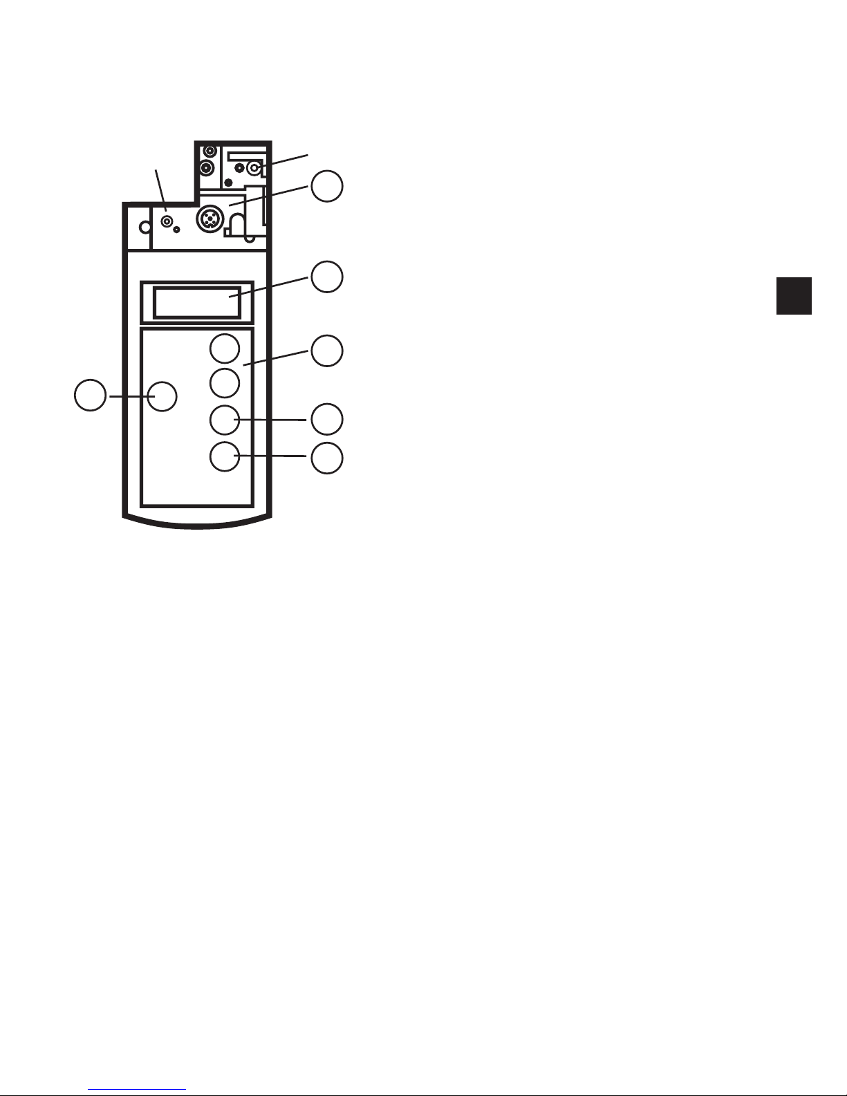
The structure of the AC1154 addressing unit is shown in the following figure:
adapter for the connection of AS-interface slaves1:
LC display2:
control panel 3:
Write/Set4:
Read/On5:
MODE6:
The adapter is used to connect the AS-interface slave to the addressing unit�
Most AS-interface slaves can be connected directly to the adapter without any
accessories�
These include, among others, AS-interface slaves with M12 screw connections� All
AS-interface slaves with 2�5 or 3�5 mm Cinch addressing socket can be programmed using the E70213 addressing cable�
Like some AS-interface slaves the addressing unit is supplied with an infrared interface which can also be used to establish the connection to AS-interface slaves
(IR addressing adapter E70211)�
A slave with a higher current consumption than provided by the addressing unit
can be powered by an external AS-i power supply�
Page 6

6
Operation with the AS-i power supply is possible but cannot be guaranteed for all
topologies� The AS-i master must be switched offline or disconnected� When operated with the AS-i power supply the addressing unit should be connected close to
the power supply�
All available slaves are then indicated in the LC display� The slave to be modified
next can be selected using the control panel�
ADDR DATA
ID12
IO
DATA
PARA
PERI
RD
WR
A
B
01234 567910 111213 14 15 16 17A
1819 20 21 22 23 24 25 26 27 28 29 30 31 B
8
The LC display shows the current operating
mode in the upper left-hand corner� Please
refer to the chapter "Operating Modes" for
the meaning and functions of the individual
modes�
To the right is the two-digit, 7-segment display� If the current AS-interface slave
does not support version 2�1 the letters A and B in the right-hand corner are not
displayed� If version 2�1 is supported, the letters indicate whether the current
address refers to slave A or B�
Page 7

7
UK
There are five buttons on the control panel which can be used to operate the
AC1154 addressing unit�
Button Function
Read/On switch on the unit•
search for the connected AS-interface slaves•
activate the next higher address (in addressing mode only)•
reread the slave information of the active slave address (not in addres-•
sing mode)
Write/Set program the slave address from the active address to the displayed •
address (in addressing mode only)
write the displayed data to the activated slave (not in addressing mode)•
Mode set the operating mode•
— set the requested address (counting downwards) or the requested data•
+ set the requested address (counting upwards) or the requested data•
Operating modes5
Before the requested operating mode can be set, the addressing unit must be
switched on by pressing the Read/On button�
The requested operating mode is set by pressing the MODE button�
Press the MODE button until the requested operating mode is indicated in the LC
display�
Modes of the connected slaves which are not supported are skipped� For a slave
of version 2�0 for example these are the modes ID1, ID2 and PERI� For all slaves
with address 0 the modes DATA and PARA are skipped since these are not defined according to the AS-interface specification�
As an alternative you can change from any mode directly to the addressing mode
by keeping the MODE button pressed�
Page 8

8
The AC1154 addressing unit supports the following operating modes:
Display
in the
LCD:
Operating mode Comments
ADDR addressing mode read and write AS-interface slave
addresses
ID read ID code
ID 1 read and write ID code 1
ID 2 read ID code 2
IO read IO code
DATA read and write data read and write input or output data
of an AS-interface slave
PARA display and write parameters display and write AS-interface slave
parameters
PERI read the peripheral fault flag
Changing the variable values in running processes can cause serious personal
injury and damage to equipment in case of malfunctioning or program errors�
Before executing the functions DATA or PARA make sure that no dangerous
conditions can occur�
Addressing mode6
When the unit is switched on by pressing the Read/On button, it is automatically in
the addressing mode and the connected slaves are displayed� If a different mode
was used before, press the MODE button until ADDR appears in the LC display�
As an alternative you can change from any mode directly to the addressing mode
by keeping the MODE button pressed�
The Read/On button must then be pressed in order to detect the connected slaves� If the addressing unit does not detect any slaves, error message F2 appears�
All detected slaves are indicated in the lower part of the display (small numbers)�
For conventional slaves neither the letter A nor B is displayed here� If new version
2�1 slaves are used, an A or B next to the address indicates whether this is an A
or B slave�
Page 9

9
UK
If several different slaves are connected to the addressing unit, the display switches between conventional A and B slaves (no letters) every 2 seconds�
The address of the slave which is to be written next (activated slave) flashes at
a frequency of 2 Hz� Press the Read/On button again to activate the next higher
available address�
To activate a specific slave, set the requested address in the upper-right field
using the + or - button� When one of the two buttons is pressed for the first time,
RD is no longer displayed� Then press the Read/On button�
The active address is indicated by RD being displayed to the left of it� In addition,
the activated address begins to flash in the lower field� The following example
should help illustrate this behaviour:
ADDR RD
1B
A
A
10
12
ADDR RD
A
B
10 11
ADDR RD
A
1 2 3
A
B
C
1
quicklyashing1:
In this example, the addressing unit detected the following slaves:
A example 1: slave address 10A and 12A
B example 2: slave address 10B and 11B
C example 3: conventional slaves with addresses 1, 2 and 3
The activated slave is reprogrammed to the address which is displayed in large
text in the upper-right corner of the display (10A in the example)�
Use the + button to increment the value or the - button to decrement the value�
Page 10

10
If the corresponding button is pressed once, the display increases or decreases
by 1� If the button is held pressed, the addressing unit increments or decrements
continuously�
To address, use the + or - button to set the new requested address� When one
of the two buttons is pressed for the first time, RD is no longer displayed� This
indicates that the displayed value is not a value read from a slave�
If the Write/Set button is pressed, the address of the activated slave (small
flashing number) is changed to the new address� In addition, WR is displayed next
to the written address� This indicates that a slave has been readdressed� Note that
no slave has the active, flashing address any longer�
Press the Read/On button to update the display and activate the next higher
address�
To readdress, address 0 must be free� If an AS-interface slave having the address
0 is connected to the AC1154 addressing unit, error message F5 appears�
If the requested address is already assigned in the AS-interface system, error
message F4 appears�
If you try to address a conventional slave with an A or B address, error message
F6 appears� If you try to readdress a version 2�1 slave to an address without the
extension A or B, error message F7 appears�
Addressing of slaves with IR interface6.1
Using this addressing unit slaves with infrared interface can be addressed� An IR
addressing adapter (E70211) is required for this�
Every action is completed by a slave reset command and thus the connected
slave can communicate with the master again�
For addressing via the IR interface proceed as follows:
Connect the IR adapter to the M12 socket of your addressing unit�•
Switch the master offline or disconnect it from the AS-i line� For the AS-i •
SilverLine power supplies from ifm the communication can be deactivated by
repositioning the shunt from position 1-2 to position 2-3 on the power supply�
Address the slave in the addressing mode�•
Switch the master online again or connect it to the AS-i line� For the new AS-i •
SilverLine power supplies from ifm put the shunt into position 1-2 again�
Page 11

11
UK
This procedure only functions if the slaves have a watchdog function�
Slaves without a watchdog must be disconnected from the AS-i voltage for a
short time after addressing so that they are detected and activated again by
the master�
When the slaves are put into service for the first time (address set at the factory
is 0) and a SilverLine power supply from ifm is used, the shunt must be put into
position 2-3 first before the power supply is switched on�
Other operating modes6.2
The following operating modes allow reading and writing of a wide range of ASinterface data� Some of these modes are for functional tests only�
In all operating modes, the slave to be read or written must first be activated in the
addressing mode (ADDR is displayed)�
Press the MODE button to set the requested operating mode�
Read ID code or ID code 2 6.3
If the Read ID code or Read ID code 2 mode is switched on by pressing the MODE button, the ID code of the activated slave is displayed� This ID code can only
be read but not written� The function Read ID code 2 is only supported by version
2�1 slaves�
Read and write ID code 1 6.4
This function is only supported by version 2�1 slaves�
If the ID1 mode is switched on by pressing the MODE button, the current value
appears in the upper-right corner of the display� In addition, RD is displayed,
indicating that the current value is a read value�
Use the + or - button to set the requested value� When one of the two buttons is
pressed for the first time, RD is no longer displayed� If the requested ID1 code
is displayed, it can be stored non volatilely in the slave by pressing the Write/Set
button�
To write ID code 1, address 0 must be free� If an AS-interface slave having
address 0 is connected to the handheld addressing unit, error message F5
appears�
If automatic addressing is used in case of a malfunction, the new slave must have
the same ID1 and ID2 codes as the slave to be exchanged�
Page 12

12
Read IO code 6.5
If the Read IO code mode is switched on by pressing the MODE button, the
display shows the IO code of the activated slave� It is not possible to change this
value�
Read and write data 6.6
This operating mode is for test purposes only� It is not possible to overwrite the
output data of the higher-level controller�
A special feature of this operating mode is that the AS-interface supply voltage is
not switched off following the read or write operation� As a result, written output
data is retained until the operating mode is changed or the connection between
the addressing unit and the AS-interface slave is interrupted� Please note that this
operating mode places a large load on the battery�
The addressing unit transmits data as long as the Write/Set or Read/On button is
pressed�
Many AS-interface products have an integrated watchdog, i�e� if no AS-interface
message has been received from the slave after a predefined period of time, the
output is switched to the safe (power-free) state� It is thus possible that set outputs
are reset when the Write/Set or Read/On button is released�
First activate the slave to be read or written�
To switch on the Read and Write Data mode, press the MODE button until DATA
is displayed� When this mode is switched on, the current input data is read and
displayed in the upper-right corner of the display�
In addition, RD is displayed, indicating that the data is read data�
To write data use the + or - button to set the requested value�
When one of the two buttons is pressed for the first time, RD is no longer displa-
yed� By pressing the Write/Set button, the data is transmitted once to the slave
and WR is displayed� If the Write/Set button is held pressed, data is transmitted to
the slave until the button is released�
Display and write parameters 6.7
This operating mode is for test purposes only� It is not possible to store or project
parameter values non volatilely in the AS-interface master or slave�
Page 13

13
UK
A special feature of this operating mode is that the AS-interface supply voltage is
not switched off following the read or write operation� Please note that this operating mode places a large load on the battery�
First activate the slave to which parameter values are to be written�
To switch on the Display and Write Parameters mode, press the MODE button
until PARA appears in the display� When this mode is switched on, the default
parameters are displayed in the upper-right corner�
In this operating mode, the parameter values are not read from the slave� When
this operating mode is switched on, the default values are displayed� If the Read/
On button is pressed again following the write operation to read the parameter
values, this display shows the values last written�
To write parameters, use the + or - button to set the requested value� When one of
the two buttons is pressed for the first time, RD is no longer displayed�
By pressing the Write/Set button, the parameters are transmitted once to the slave
and WR is displayed� As long as the activated AS-interface slave is connected to
the addressing unit or as long as the PARA operating mode is switched on, the
slave functions using the written parameter values�
If the connection is interrupted or the operating mode is changed, the values are
lost�
Due to the structure of the unit, pressing the MODE button first switches on the
PARA operating mode� Press the button again to switch on the DATA operating
mode� If you switch from the PARA operating mode to the DATA operating mode,
the AS-interface voltage remains switched on and the parameter value is retained�
Indication of the peripheral fault flag 6.8
The peripheral fault flag is an optional bit which indicates an error in the slave�
This function is only supported by version 2�1 slaves� This flag can be read using
the addressing unit�
Activate the slave from which this bit is to be read�
Press the MODE button until PERI appears in the display� If 0 is displayed, no
error is present, 1 indicates an error�
Page 14

14
Error messages7
The addressing unit supports the following error messages:
Error
code
Meaning Description
F1 overload AS-interface too high current consumption of the slaves
connected to the addressing unit
F2 slave not found no slave found at the active address
F3 error during programming during programming of the address or of
the extended IC code 1 the value could not
be permanently stored in the EEPROM of
the slave
F4 target address assigned the target address to which the activated
slave is to be readdressed is assigned
F5 address 0 assigned when readdressing a slave or when writing
the extended ID code 1, address 0 must be
free this address is used by a connected
slave
F6 standard slave instead of
extended slave found
the operation cannot be executed as the
activated slave is not a version 2�1 slave
F7 extended slave found
instead of standard slave
the standard slave at the active address
was exchanged for a version 2�1 slave
F8 reception error due to an error the response of the slave
could not be received correctly
If error code F1 is displayed, the handheld addressing unit is not able to provide
sufficient supply current� This can be corrected by connecting an AS-interface
power supply�
Error message F6 always occurs when a standard slave is activated and you
switch from the addressing mode to one of the modes Read IO code, Display
and Write Parameter Values or Read and Write Data� Pressing the MODE button
activates operating modes which are not supported by the standard slave�
Error code F7 always occurs when you attempt to set a version 2�1 slave to an
address when neither the extension A nor B is shown in the display�
Page 15

15
UK
 Loading...