

Page 1
Original operating instructions
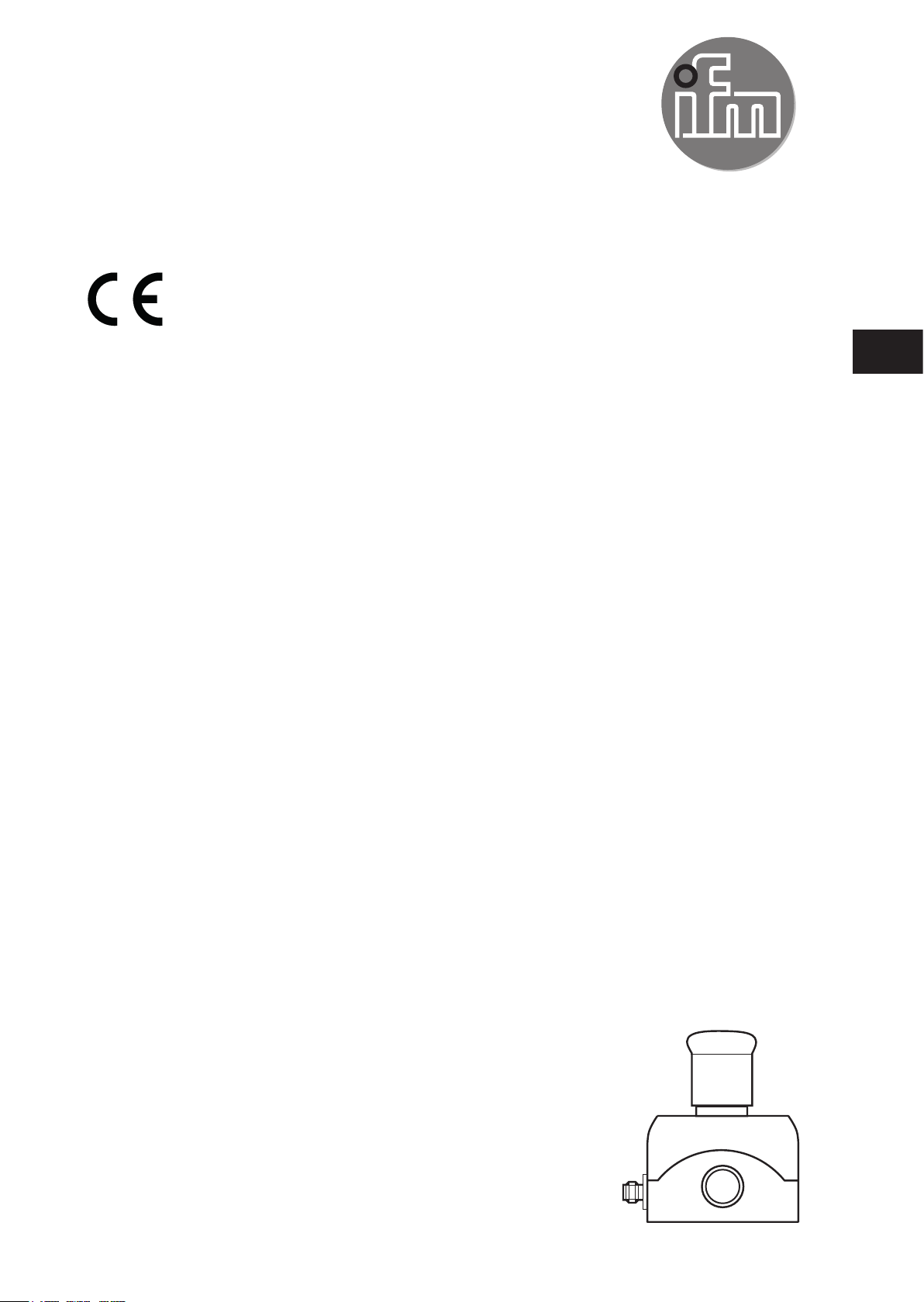
Compact AS-i E-STOP safety module
AC010S
UK
80269280/00 08/2017
Page 2

Contents
1 Preliminary note ��������������������������������������������������������������������������������������������������� 3
1�1 Explanation of symbols ����������������������������������������������������������������������������������3
2 Safety instructions �����������������������������������������������������������������������������������������������3
2�1 Safety-related requirements regarding the application ���������������������������������� 4
3 Items supplied������������������������������������������������������������������������������������������������������4
4 Functions and features ����������������������������������������������������������������������������������������4
5 Function and electrical connection ����������������������������������������������������������������������5
6 Installation������������������������������������������������������������������������������������������������������������6
6�1 Operating and display elements ��������������������������������������������������������������������6
7 Electrical connection �������������������������������������������������������������������������������������������� 7
8 Addressing ����������������������������������������������������������������������������������������������������������� 8
9 Operation ������������������������������������������������������������������������������������������������������������� 8
9�1 Response times ��������������������������������������������������������������������������������������������� 8
10 Safety characteristics�����������������������������������������������������������������������������������������9
11 Technical data ��������������������������������������������������������������������������������������������������10
12 Scale drawing �������������������������������������������������������������������������������������������������� 11
13 Troubleshooting �����������������������������������������������������������������������������������������������12
14 Maintenance, repair and disposal �������������������������������������������������������������������� 12
15 Approvals/Certificates �������������������������������������������������������������������������������������� 12
2
Page 3
1 Preliminary note
Technical data, approvals, accessories and further information at
www�ifm�com�
The instructions are part of the unit� They are intended for authorised persons
according to the EMC, Low Voltage and Machinery Directive and safety
regulations�
The instructions contain information about the correct handling of the product�
Read the instructions before use to familiarise yourself with operating conditions,
installation and operation�
Adhere to the safety instructions�
1.1 Explanation of symbols
►
Request for action
Important note
WARNING
UK
Warning of dangers which may lead to death or serious
irreversible injuries�
2 Safety instructions
• Follow the operating instructions�
• In case of non-observance of notes or standards, especially when tampering
with and/or modifying the unit, any liability and warranty is excluded�
• The unit must be installed, connected and put into operation by a qualified
electrician trained in safety technology�
• The applicable technical standards for the corresponding application must be
complied with�
• For installation the requirements according to EN 60204 must be observed�
• In case of malfunction of the unit please contact the manufacturer� Tampering
with the unit is not allowed�
• Disconnect the unit externally before handling it� Also disconnect any
independently supplied relay load circuits�
• After setup the system has to be subjected to a complete function check�
• In case of any questions - if required - contact the safety expert in charge of
your country�
3
Page 4

WARNING
In case of improper handling of the product, the safety and physical
integrity of operators and machinery cannot be guaranteed.
Death or serious irreversible injuries may result�
► Note all remarks on installation and handling given in these instructions�
► The device must only be used under the specified operating conditions and in
accordance with use as prescribed below�
2.1 Safety-related requirements regarding the application
It must be ensured that the safety requirements of the respective application
correspond to the requirements stated in these instructions�
Observe the following requirements:
► Adhere to EN 14119 for interlocking devices associated with guards�
► Adhere to the specified operating conditions (→ chapter 11 Technical data).
Use of the unit in the vicinity of chemical and biological media is not permitted�
► In case of faults within the unit which result in the defined safe state: take
measures to maintain the safe state when the complete control system
continues to be operated�
► Replace damaged units�
3 Items supplied
1 compact AS-i E-STOP safety module, 1 AC010S operating instructions with the
reference number 80269280�
If one of the above-mentioned components is missing or damaged, please contact
one of the ifm branch offices�
4 Functions and features
The compact AS-i E-STOP safety module (AC010S) is used to detect safety-
related switching states� For this purpose a code table is transferred via the AS-i
system with 8 x 4 bits which is evaluated by the safety monitor (e�g� AC001S ���
AC004S, AC032S, AC041S).
4
Page 5

When operated correctly, the system can be used in applications up to the
Performance Level e according to EN ISO 13849-1 or IEC 61508/SIL3 (see notes
Electrical connection).
Depending on the safety components used the complete safety system can
also be classified for a lower control category!
5 Function and electrical connection
Please refer to all information in the description of the configuration software (e�g�
E7050S) and the installation instructions of the unit. These documents provide
all required instructions concerning installation, configuration, operation and
maintenance of the compact AS-i E-STOP safety module�
Information on the parameterizable safety functions of the compact AS-i E-STOP
safety module can be found in the chapter "Monitoring devices" (two positively
guided NC contacts) of the configuration software manual.
The products described herein are designed to be components of a safety-
UK
oriented machine or control system� A complete safety-related system
normally includes sensors, evaluation units, signalling components and
concepts for safe switch-off� It is the responsibility of each manufacturer of a
machine or installation to ensure a correct functioning of the whole system�
The manufacturer of the safe AS-i module, his subsidiaries and affiliates are
not in a position to evaluate all of the characteristics of a given machine or
product not designed by him�
The manufacturer accepts no liability for any recommendation that may be implied
or stated herein�
The warranty contained in the contract of sale is the sole warranty� Any statements
contained herein do not create new warranties or modify existing ones�
Compliance with the description of the configuration software and with the
operating instructions of the AS-i safety monitor and compact AS-i E-STOP safety
module is mandatory!
5
Page 6

Maintenance requirement
A minimum of one testing per year is compulsory by a demand on the safety
function!
6 Installation
► Fasten the compact AS-i E-STOP safety module onto a mounting device� The
upper part of the housing must be fixed to the lower part using all four screws!
6.1 Operating and display elements
1
6
5
1: M12 connector
2: LEDs
3: LED
4: 4 mounting holes
5: E-STOP, illuminated
fool-proof to ISO 13850; pull to reset
6: 4 xing screws (upper part of the housing)
2
3
4
6
Page 7

7 Electrical connection
Connect the compact AS-i E-STOP safety module to the AS-i system via the M12
connector� The supply comes from the AS-i system�
Do not connect the AS-i potential to an external potential�
2
M12 connector
AS-i -
3
2
M12 connector Pin
4
5
1 AS-i +
AS-i + 1
AS-i - 3
3
4
UK
1: Do not change the electrical connections!
2: M12 connector
3: LED red / LED green / LED yellow (cannot be seen when the unit is closed)
4: LED red, alarm output
Data bits
Data bit D3 D2 D1 D0
In/Out SI-2 SI-2 SI-1 SI-1/O-1
Activated input channel Bit sequence D3-D0
SI-1 XX00
SI-2 00XX
SI-1 and SI-2 0000
none XXXX
Activated alarm output Bit sequence D3-D0
O-1 XXX1
X = random
7
Page 8

The code words 0000, XX00 and 00XX cause the AS-i safety monitor to bring the
installation into the safe state�
For more details on the effect of the data bits on the transmission sequence refer
to the configuration software manual (see the chapter "Monitoring devices").
8 Addressing
When mounted the compact AS-i E-STOP safety module can be addressed via
the M12 connector and the jumper cable, e�g� EVC011 using the addressing unit
AC1154� Assign a free address between 1 and 31� At the factory the address is set
to 0�
Addressing via the M12 connector is only allowed when disconnected�
9 Operation
Check whether the unit operates correctly� Indication by LEDs on the PCB:
• LED green: supply voltage OK
• LED red is lit: AS-i communication error, slave does not participate in the
"normal" exchange of data, e�g� slave address 0
• LED red flashes: peripheral fault, e�g� sensor supply overloaded or shorted
• LED yellow: inputs switched
• LED alarm red: alarm output O-1 (unsafe)
(Through the host system the alarm output LED can be set as a static or
dynamic output.)
Overload and short circuit of the input supply are signalled to the AS-i
master (version 2.1) via the "periphery fault" flag in the status register.
Accessories (optional)
E-STOP label in four languages (German, English, French, Italian); order no.
E7003S�
9.1 Response times
The response time of the E-STOP safety module for a safety request is max�
10 ms�
8
Page 9

Calculation of the total response time:
For the calculation of the response time of the complete system the response
times of the other components also have to be added (mechanical contacts, safety
monitor and external relays or contactors possibly connected to the safety monitor
output).
Example:
The response time of the E-STOP safety module for a safety request is max�
10 ms. In addition the response time of the safety monitor (e.g. AC001S) has to
be taken into account which is max� 40 ms including data transfer� The sum of
the individual responses results in a total response time of max� 50 ms before
UK
application of the signal to AC010S until the safe outputs of the safety monitors
switch� Here, the switching times of the external relays and contactors connected
to the relay output of the safety monitor have not been taken into account�
10 Safety characteristics
Characteristics Value
Safety integrity level SIL 3
Category cat� 4
Service life T 20 years
PFD
PFH
avg
D
7�9 • 10
1�8 • 10
-6
-10
/ h
• These calculations were made on the basis of an ambient temperature of
40 °C�
• The device meets the requirements of EN ISO 13849-1: 2015; PL e
(category 4), SIL 3 (IEC 61508) and can be used in applications up to SIL 3 /
PL e�
• The PFD / PFH values and MTTFd values of the other components, especially
of the AS-i safety monitor, can be found in the corresponding documentation�
9
Page 10

Explanation of the abbreviations:
SIL Safety Integrity Level Safety Integrity Level SIL 1-4 to IEC 61508� The
higher the SIL the lower the probability that a
safety function will fail�
PL Performance Level Capability of safety-related parts to perform a
safety function at predictable conditions to fulfil the
expected risk reduction�
PFD
avg
Probability of failure on
demand
PFH
D
Probability of Dangerous
Failure per Hour
T Life time Max� service life�
11 Technical data
Electrical design 2 safe inputs / 1 non-safe LED output
Operating voltage 26�5���31�6 V DC
Current consumption < 50 mA
Inputs
Wiring DC PNP
Voltage supply via AS-i
Voltage range ≥ 20 V DC
Short-circuit proof yes
Input current high/low 4 mA
LED output
Supply via AS-i yes
Short-circuit proof no
Integrated watchdog yes
Max� current load output 10 mA
LED red
Ambient temperature -25���60 °C
Protection rating IP 67
AS-Interface /
version 2�1 / no
extended addressing mode possible
AS-i profile S-7�B�E
I/O configuration 7 [Hex]
10
Page 11

ID code B�E [Hex]
AS-i certificate 74601
Maximum number of
compact AS-i E-STOP safety
31
modules
EMC EN 61000-6-4; EN 62026-2
Housing materials PC-GF20 (polycarbonate)
Housing dimensions 80 x 72 x 105 mm (HxWxD)
Connection M12x1 connector
12 Scale drawing
UK
58,5
105
56
93,5
72
M12x1
66,5
80
11
Page 12

13 Troubleshooting
The LEDs of the compact AS-i E-STOP safety module indicate faulty operating
states ( → chapter 9 Operation).
14 Maintenance, repair and disposal
If used correctly no maintenance and repair measures are necessary�
Only the manufacturer is allowed to repair the unit�
After use dispose of the unit in an environmentally friendly way in accordance with
the applicable national regulations�
15 Approvals/Certificates
• EC declaration of conformity
• AS-Interface
• TÜV Nord
• UL (cULus)
12
Page 13

UK
13
 Loading...