

Page 1

Operating instructions
Diffuse reflection sensor with
background suppression
and IO-Link
O8H2
706432 / 00 05 / 2017
UK
Page 2

2
Content
1 Preliminary note ��������������������������������������������������������������������������������������������������� 3
1�1 Symbols used ������������������������������������������������������������������������������������������������3
2 Functions and features ����������������������������������������������������������������������������������������3
3 Installation������������������������������������������������������������������������������������������������������������3
4 Operating and display elements ��������������������������������������������������������������������������4
5 Electrical connection �������������������������������������������������������������������������������������������� 4
5�1 PNP ���������������������������������������������������������������������������������������������������������������4
5�2 NPN ���������������������������������������������������������������������������������������������������������������5
6 Setting the range �������������������������������������������������������������������������������������������������5
6�1 Setting the range by means of background and object ���������������������������������5
6�2 Setting the range by means of the background ��������������������������������������������� 6
6�3 Setting the maximum range ���������������������������������������������������������������������������7
7 IO-Link �����������������������������������������������������������������������������������������������������������������8
7�1 General information ���������������������������������������������������������������������������������������8
7�2 Device-specific information ����������������������������������������������������������������������������8
7�3 Parameter setting tools ����������������������������������������������������������������������������������8
7�4 Setting parameters via IO-Link ����������������������������������������������������������������������8
8 Operation ������������������������������������������������������������������������������������������������������������� 9
9 Maintenance, repair, disposal ������������������������������������������������������������������������������ 9
Page 3
3
UK
1 Preliminary note
1.1 Symbols used
► Instruction
> Reaction, result
[…] Designation of pushbuttons, buttons or indications
→ Cross-reference
Important note
Non-compliance can result in malfunctions or interference�
2 Functions and features
The diffuse reflection sensor detects objects and materials without contact and
indicates their presence by a switching signal�
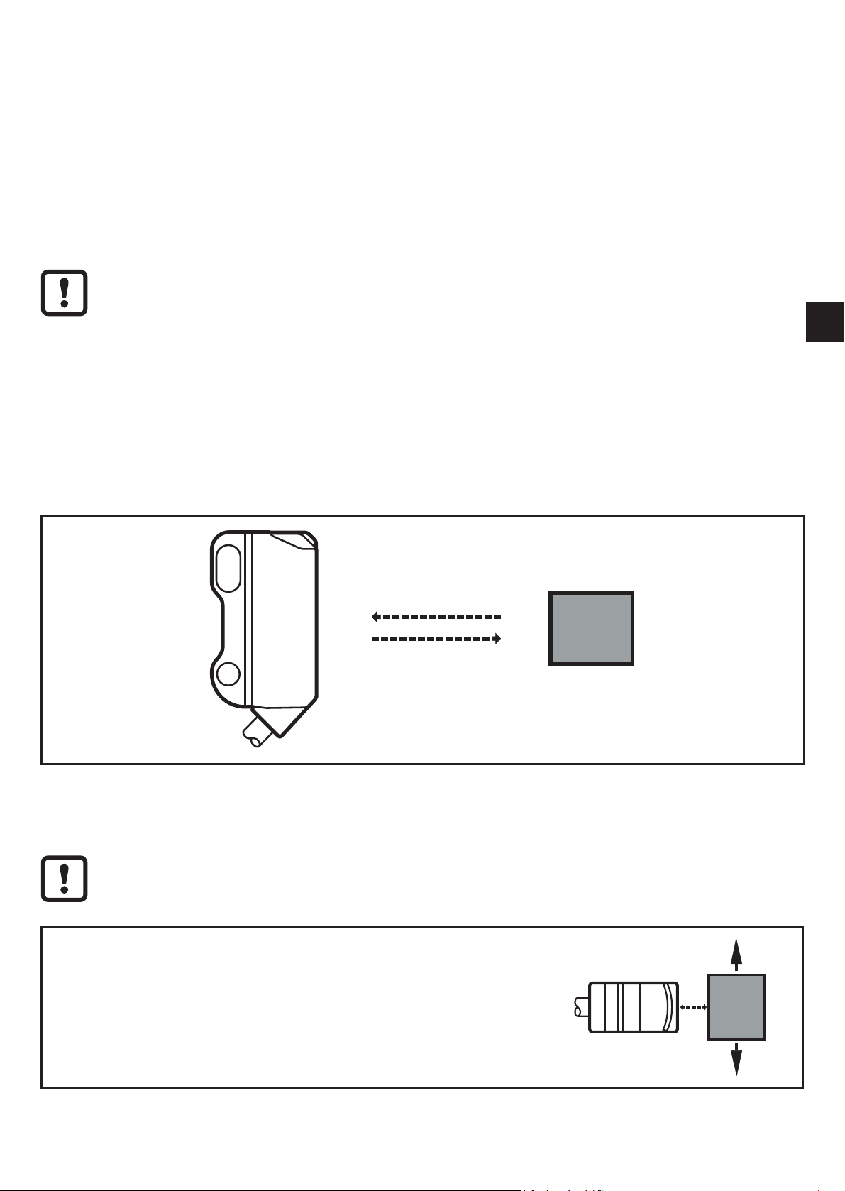
3 Installation
► Secure it to a bracket�
► Align the diffuse reflection sensor to the object to be detected�
Mount the diffuse reflection sensor with a tightening torque of max� 1 Nm�
Note:
The objects to be detected are to move transversely to the
lens of the sensor�
► In case of other directions of movement it should be
tested before whether safe switching is guaranteed�
Page 4

4
4 Operating and display elements
1 2
1: LED yellow - switching output active
2: LED green - operation
5 Electrical connection
The unit must be connected by a qualified electrician�
► The national and international regulations for the installation of
electrical equipment must be adhered to�
► Ensure voltage supply to EN 50178�
► Disconnect power�
► Connect the unit as follows:
5.1 PNP
Cable *
Connector M8 3-pin pigtail Connector M8 4-pin pigtail
214
3
* Core colours: BN = brown, BU = blue, BK = black
Page 5

5
UK
5.2 NPN
Cable *
L
BN
BK
BU
L
+
Connector M8 3-pin pigtail Connector M8 4-pin pigtail
L
+
L
1
4
3
214
3
L
+
L
1
4
3
* Core colours: BN = brown, BU = blue, BK = black
6 Setting the range
The settings indicated in this chapter only apply to IO-Link capable
PNP diffuse reflection sensors�
6.1 Setting the range by means of background and object
1� Start the LR DEVICE software�
2� Align the diffuse reflection sensor to the object�
TP1
TP1: teach point 1
3� Press button [Teach SP1 TP1] in the LR DEVICE software�
Page 6

6
4� Align the diffuse reflection sensor to the background�
TP2TP1
TP1: teach point 1
TP2: teach point 2
5� Press button [Teach SP1 TP2] in the LR DEVICE software�
> The switch point SP1 is between object and background�
TP2TP1 SP1
Zone „object recognised“
Either the object can be set first and then the background, or the other
way around�
6.2 Setting the range by means of the background
If the object is not available, the range can be set using only the background�
The switching characteristics of the diffuse reflection sensor are the most
reliable if the range is set using the background and the object�
1� Start the LR DEVICE software�
Page 7

7
UK
2� Align the diffuse reflection sensor to the background�
3� Press button [Teach Custom - SP1 without target] in the LR DEVICE
software�
> The switch point SP1 is just in front of the background�
SP1
Zone „object recognised“
6.3 Setting the maximum range
1� Start the LR DEVICE software�
2� Align the diffuse reflection sensor to an empty area without object or
background�
> The diffuse reflection sensor must not receive any light from the object or the
background�
3� Press button [Teach Custom - SP1 without target] in the LR DEVICE
software�
Page 8

8
7 IO-Link
7.1 General information
This unit has an IO-Link communication interface which requires an IO-Linkcapable module (IO-Link master) for operation� The IO-Link interface enables
direct access to the sensor values and parameters and provides the possibility
to set the parameters of the unit during operation� In addition communication is
possible via a point-to-point connection with a USB adapter cable�
You will find more detailed information about IO-Link at www�ifm�com/uk/io-link�
7.2 Device-specific information
You will find the IODDs necessary for the configuration of the IO-Link device and
detailed information about sensor values, diagnostic information and parameters
in the overview table at www�ifm�com/uk/io-link�
7.3 Parameter setting tools
You will find all necessary information about the required IO-Link hardware and
software (e�g� ifm LR DEVICE) at www�ifm�com/uk/io-link�
7.4 Setting parameters via IO-Link
Among others, the following parameters can be set via IO-Link�
A table of all adjustable parameters can be found at
www�ifm�com/uk/io-link�
IO-Link parameter name Parameter
SSC1 Param�SP1 Target value range
SSC1 Config�Logic
Switch point logic / status for the detected object
High active: light-on mode - normally open
Low active: dark-on mode - normally closed
(→ 8 Operation)
SSC1 Switch-On delay Switch-on delay
SSC1 Switch-Off delay Switch-off delay
Transmitter configuration Transmitted light ON / OFF
Sequence modulation Anti-crosstalk function ON / OFF
Teach SP1 TP1 / Teach SP1 TP2
Setting the range by means of object and
background
Page 9

9
UK
IO-Link parameter name Parameter
Teach Custom – SP1 without target Setting the range by means of the background
8 Operation
► Check whether the unit operates correctly�
> The green LED is lit when the supply voltage is applied and the sensor signal
is stable�
> Dark-on mode - normally closed: the output is switched / the yellow LED is lit
when no object is detected�
> Light-on mode - normally open: the output is switched / the yellow LED is lit
when an object is detected�
9 Maintenance, repair, disposal
► Keep the lens of the sensor free from soiling�
► For cleaning do not use any solvents or cleaning agents which could damage
the plastic parts�
► After use dispose of the unit in an environmentally friendly way in accordance
with the applicable national regulations�
Faulty sensors must only be repaired by the manufacturer�
Technical data and further information at www�ifm�com
 Loading...