

Page 1
Operating instructions
5-segment signal lamp
DV15x0
DV25x0
UK
80263024 / 00 07 / 2019
Page 2

Contents
1 Preliminary note ��������������������������������������������������������������������������������������������������� 4
1�1 Key to the symbols ����������������������������������������������������������������������������������������4
2 Safety instructions �����������������������������������������������������������������������������������������������5
3 Functions and features ����������������������������������������������������������������������������������������5
3�1 IO-Link �����������������������������������������������������������������������������������������������������������6
3�1�1 General information ������������������������������������������������������������������������������6
3�1�2 Device-specific information �������������������������������������������������������������������6
4 Installation������������������������������������������������������������������������������������������������������������6
5 Electrical connection �������������������������������������������������������������������������������������������� 7
5�1 IO-Link connection �����������������������������������������������������������������������������������������7
6 Pin configuration �������������������������������������������������������������������������������������������������� 8
6�1 IO-Link device (DV25x0) �������������������������������������������������������������������������������8
6�2 Standard device (DV15x0) ����������������������������������������������������������������������������8
7 Operating and display elements ��������������������������������������������������������������������������9
8 Operation ����������������������������������������������������������������������������������������������������������� 10
8�1 Operation of the IO-Link version ������������������������������������������������������������������10
8�1�1 General ����������������������������������������������������������������������������������������������� 10
8�1�2 On/off mode ���������������������������������������������������������������������������������������� 10
8�1�3 RGB mode ������������������������������������������������������������������������������������������ 11
8�1�4 Analogue mode �����������������������������������������������������������������������������������12
8�2 Operation of the standard version ���������������������������������������������������������������14
8�3 Demo mode �������������������������������������������������������������������������������������������������14
9 Parameter setting ����������������������������������������������������������������������������������������������14
9�1 IO-Link version���������������������������������������������������������������������������������������������14
9�2 Standard version �����������������������������������������������������������������������������������������15
9�2�1 Parameter structure ���������������������������������������������������������������������������� 16
10 Scale drawing ��������������������������������������������������������������������������������������������������17
10�1 DVx500 ������������������������������������������������������������������������������������������������������ 17
10�2 DVx510 ������������������������������������������������������������������������������������������������������ 18
10�3 DVx520 ������������������������������������������������������������������������������������������������������ 19
10�4 DVx530 ������������������������������������������������������������������������������������������������������ 20
2
Page 3

11 Technical data ��������������������������������������������������������������������������������������������������21
11�1 IO-Link device ��������������������������������������������������������������������������������������������21
12 Maintenance, repair and disposal �������������������������������������������������������������������� 22
12�1 Cleaning the housing surface ��������������������������������������������������������������������22
13 Approvals/standards ����������������������������������������������������������������������������������������22
UK
3
Page 4
1 Preliminary note
Technical data, approvals, accessories and further information at
www�ifm�com�
1.1 Key to the symbols
► Instructions
> Reaction, result
[…] Designation of keys, buttons or indications
→ Cross-reference
Important note
Non-compliance may result in malfunction or interference�
Information
Supplementary note�
WARNING
Warning of serious personal injury�
Death or serious irreversible injuries may result�
CAUTION
Warning of personal injury�
Slight reversible injuries may result�
ATTENTION
Warning of damage to property
4
Page 5

2 Safety instructions
• Read this document before setting up the product and keep it during the entire
service life�
• The product must be suitable for the corresponding applications and
environmental conditions without any restrictions�
• Only use the product for its intended purpose (→ 3 Functions and features)�
• If the operating instructions or the technical data are not adhered to, personal
injury and/or damage to property may occur�
• The manufacturer assumes no liability or warranty for any consequences
caused by tampering with the product or incorrect use by the operator�
• Installation, electrical connection, set-up, operation and maintenance of the
product must be carried out by qualified personnel authorised by the machine
operator�
• Protect units and cables against damage�
UK
3 Functions and features
The unit is used to visually display machine conditions� The versions DVx510 and
DVx530 additionally have a buzzer for acoustic signalling�
The 5 LED segments and the audible warning device can be switched on and off
individually�
► The device is intended for indoor use only�
Observe the operating conditions (→ 11 Technical data)�
► The unit must not be used for safety-related applications such as
access control�
The standard units are DV15xx� The DV25xx units are IO-Link devices� The
IO-Link version can be triggered and configured via the standard IO-Link
interface� With the standard version the individual LED segments can be switched
individually via digital inputs� Parameters are set via a parameter setting button or
via an additional IO-Link interface�
If the equipment is used in a manner not specified by the manufacturer, the
protection provided by the equipment may be impaired�
5
Page 6
3.1 IO-Link
1
43
3.1.1 General information
This unit has an IO-Link communication interface which enables direct access to
process and diagnostic data� In addition it is possible to set the parameters of the
unit while it is in operation� Operation of the unit via an IO-Link interface requires
an IO-Link capable module (IO-Link master)�
3.1.2 Device-specific information
With a PC, suitable IO-Link software and an IO-Link adapter cable communication
is possible when the system is not in operation� The IODDs necessary for the
configuration of the unit, detailed information about process data structure,
diagnostic information, parameter addresses and the necessary information about
the required IO-Link hardware and software can be found at www�ifm�com�
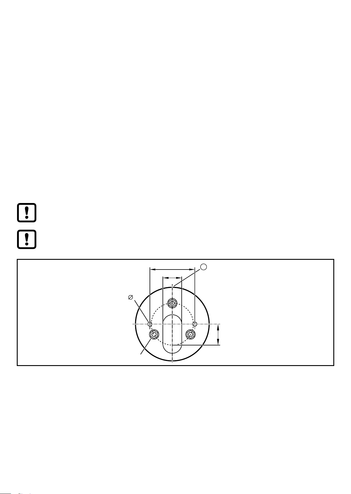
4 Installation
► Disconnect power before installation�
► For installation choose a flat mounting surface�
18
4
20
M4
Fixture (view from bottom)
1: Front side
► Attach the fixture for the unit to the mounting surface using the supplied M4
nuts� Tightening torque 1�8 Nm�
► Only with the models DVx500 and DVx510:
For mounting on a horizontal surface attach the base to the fixture (overlapping
marks on base and fixture) and turn clockwise by approx� 10 ° to fix it� For
mounting on a vertical surface loosen the screw in the base, turn the upper part
6
Page 7

of the base by 180 ° and tighten the screw again� Attach the base to the fixture
(overlapping marks on base and fixture) and turn clockwise by approx� 10 ° to
fix it�
► Insert the cable through the fixture and, if necessary, the base and connect the
socket with the M12 connector in the signal lamp� Tightening torque max� 1
Nm�
► Attach the signal lamp to the fixture or the base (overlapping marks) and turn
clockwise by approx� 10 ° to fix it�
Observe the maximum tightening torque of the connection cable�
Integrated seals at the bottom of the fixture and in the base as well as
O-rings at the fixture and base prevent ingress of moisture�
More information about available accessories at www�ifm�com
5 Electrical connection
The unit must be connected by a qualified electrician�
The national and international regulations for the installation of electrical
equipment must be adhered to�
Voltage supply according to SELV, PELV
► Disconnect power�
► Connect the unit�
UK
5.1 IO-Link connection
The IO-Link port must be connected according to the IO-Link specification�
7
Page 8

6 Pin configuration
43
5
6.1 IO-Link device (DV25x0)
M12 connector IO-Link, 4 poles
(4 x 0�34 mm² / AWG 22)
1: UB+
2: not used
3: UB4: IO-Link
6.2 Standard device (DV15x0)
M12 connector, 8 poles
(8 x 0�25 mm² / AWG 24)
1: LED segment 5
2 1
2: buzzer (DV1510 and DV1530)
3: LED segment 3
4: LED segment 2
5: voltage supply
6: LED segment 1
7: LED segment 4
8: IO-Link
The input polarity is selectable�
► Connect pin 5 to +24 V DC to trigger the inputs with an NPN transistor�
► Connect pin 5 to GND to trigger the inputs with a PMP transistor�
When triggered via IO-Link (pin 8) without connection cable E12572:
► Connect pin 5 to +24 V DC�
► Connect pin 3 to GND�
3
4
2
1
8
7
6
8
Page 9

7 Operating and display elements
1
3
8
2
4
5
6
7
UK
1: Parameter setting button (only DV15x0)
2: LED segment 1 with 4 RGB LEDs
3: LED segment 2 with 4 RGB LEDs
4: LED segment 3 with 4 RGB LEDs
5: LED segment 4 with 4 RGB LEDs
6: LED segment 5 with 4 RGB LEDs
7: Buzzer (only DVx510 and DVx530)
8: Feedback LED (only DV15x0)
9
Page 10

8 Operation
8.1 Operation of the IO-Link version
8.1.1 General
The unit is connected to an IO-Link master (A port) with a 4-pole connection cable�
The controller switches the individual LED segments on and off in the configured
colours according to the set parameters�
Via the parameter "Operating mode" the following modes can be set:
• On/off mode
• RGB mode
• Analogue mode
8.1.2 On/off mode
While in operation, the controller switches the 5 LED segments and the buzzer
(only with DVx510 and DVx530) on and off (PDout, cyclical data communication)�
Signalling corresponds to the pre-defined parameters for the individual LED
segments and the buzzer�
Via the acyclic parameter setting the following properties can be set for every LED
segment:
• Colour (red, green, orange, blue, violet, turquoise, white, yellow, off)
• Frequency (permanently on, low flash rate slow/medium/fast, high flash rate
slow/medium/fast)
• Brightness (100 %, 75 %, 50 %, 25 %)
For the models with an acoustic signal device the audibility of the buzzer can be
set�
7 6 5 4 3 2 1 0 PDout
10
Seg� 5 Seg� 4 Seg� 3 Seg� 2 Seg� 1 Byte 0
Buzzer sound (buzzer style
1���8)
Byte 1
Byte 2
Byte 3
Byte 4
Buzzer Byte 5
Page 11

8.1.3 RGB mode
While in operation the controller switches the 5 LED segments and the buzzer on
and off (only with DVx510 and DVx530), defining the respective properties (PDout,
cyclical data communication)�
In this operating mode, 8 different acoustic signals are available for the buzzer�
7 6 5 4 3 2 1 0 PDout
Segment 1 LED properties Seg� 1
yellow
Segment 2 LED properties Seg� 2
yellow
Segment 3 LED properties Seg� 3
yellow
Segment 4 LED properties Seg� 4
yellow
Segment 5 LED properties Seg� 5
yellow
Buzzer sound (buzzer style
1���8)
Seg� 1
red
Seg� 2
red
Seg� 3
red
Seg� 4
red
Seg� 5
red
Seg� 1
green
Seg� 2
green
Seg� 3
green
Seg� 4
green
Seg� 5
green
Seg� 1
blue
Seg� 2
blue
Seg� 3
blue
Seg� 4
blue
Seg� 5
blue
Buzzer Byte 5
The properties of the LED segments are defined as follows:
Byte 0
Byte 1
Byte 2
Byte 3
Byte 4
UK
3 2 1 0 Colour
0 0 0 0 off
0 1 0 0 red
0 0 1 0 green
0 1 1 0 orange
0 0 0 1 blue
0 1 0 1 violet
0 0 1 1 turquoise
0 1 1 1 white
1 0 0 0 yellow
11
Page 12

6 5 4 Frequency
0 0 0 permanently on
0 0 1 low flash rate slow
0 1 0 low flash rate medium
0 1 1 low flash rate fast
1 0 0 high flash rate slow
1 0 1 high flash rate medium
1 1 0 high flash rate fast
8.1.4 Analogue mode
While in operation the controller transmits an analogue value between 0 and
100 % in byte 0 via PDout %� Byte 1 determines the representation of the visual
signalling� 9 different representations are possible�
Byte 5 defines the acoustic signal (only with DVx510 and DVx530)� 8 different
acoustic signals are available�
7 6 5 4 3 2 1 0 PDout
Analogue value 0���100 % Byte 0
Representation LED (style 1���9) Byte 1
Byte 2
Byte 3
Byte 4
Buzzer sound (buzzer style
1���8)
Buzzer Byte 5
12
Page 13

The signal lamp generates the following visual indications of the analogue value
91-99 %81-90 %71-80 %61-70 %51-60 %41-50 %31-40 %21-30 %11-20 %1-10 %0 %Analogue value: 100 %
Style 1
Style 5
Style 2
Style 3
Style 4
Style 8
Style 9
Style 6
Style 7
Style 10
depending on the data in byte 1�
white
white white white white
white white white
white white white white
white white white
green
green
green
green
blue blue blue
blue blue blue
orange
orange
orange
orange
blue blue
white white
white white
yellow
yellow
yellow
yellow
blue blue blue
red
red
red
red
green
green
green
green
red
red
red
red
orange
orange
orange
orange
blue
yellow
yellow
yellow
yellow
green
green
green
green
orange
orange
orange
orange
white white white
white white
yellow
yellow
yellow
yellow
red
red
red
red
white
white
white
white
white
green
green
green
blue blue
green
blue blue
orange
orange
orange
blue blue
orange
white
white
yellow
yellow
yellow
blue blue
yellow
red
red
red
red
white
white
white
white
white
white
white
white
green
green
green
green green
orange
orange
orange
orange
white
white
white
yellow
yellow
yellow
yellow
red
red
red
red
white
white
white
white
white
white
white
white
white
white
green
green
blue blueblue
green
red
red
blue blueblue
red
red
orange
orange
blue blue
orange
orange
white
white
white
white
white
white
yellow
yellow
blue blueblue
yellow
yellow
whitewhite
white
white
white
white
white
whitewhite
white
white
white
white
white
green
green
green
green
red
red
red
red
orange
orange
blue
orange
orange
white
white
white
white
white
white
yellow
yellow
yellow
yellow
white
white
white
white
white
white
white
white
white
white
white
white
white
white
white
white
green green
blueblue blueblue
green
green
green
blueblue blueblue
orange
blueblue blueblue
orange
orange
orange
white
white
white
white
white
white
white
white
yellow
blueblue blueblue
yellow
yellow
yellow
red
red
red
red
white
white
white
white
white white
white
white
white
white
white
white
white
white white
white
white
white
green
green
green
red
red
red
red
orange
orange
orange
orange
white
white
white
white
white white
white
white
white
yellow
yellow
yellow
yellow
white
white
white
white
white
white
white
white
white
white
white
white
white
white
white
white
white
white
blueblue blueblue blueblue
green
green
green
green
blueblue blueblue blueblue
blueblue blueblue blueblue
orange
orange
orange
orange
white
white
white
white
white
white
white
white
white
blueblue blueblue blueblue
yellow
yellow
yellow
yellow
red
red
red
red
white
white
white
white
white
white
white
white
white
white
white
white
white
white
white
white
white
white
white
white
green
green
green
green
red
red
red
red
orange
orange
orange
orange
white
white
white
white
white
white
white
white
white
white
yellow
yellow
yellow
yellow
orange
orange
orange
orange
yellow
yellow
yellow
yellow
white
white
white
white
white
white
white
white
white
white
white
white
white
white
white
white
white
white
white
white
green
green
green
green
red
red
red
red
white
white
white
white
white
white
white
white
white
white
Segment 1
Segment 2
Segment 3
Segment 4
Segment 5
Segment 1
Segment 2
Segment 3
Segment 4
Segment 5
UK
Segment 1
Segment 2
Segment 3
Segment 4
Segment 5
Segment 1
Segment 2
Segment 3
Segment 4
Segment 5
Segment 1
Segment 2
Segment 3
Segment 4
Segment 5
Segment 1
Segment 2
Segment 3
Segment 4
Segment 5
Segment 1
Segment 2
Segment 3
Segment 4
Segment 5
Segment 1
Segment 2
Segment 3
Segment 4
Segment 5
Segment 1
Segment 2
Segment 3
Segment 4
Segment 5
Segment 1
Segment 2
Segment 3
Segment 4
Segment 5
13
Page 14

8.2 Operation of the standard version
The unit is connected to the digital outputs of the controller via an 8-pole cable
(see accessories at www�ifm�com)� The 6 HTTL inputs of the signal lamp are
triggered with 24 V DC� According to the set parameters, the 5 LED segments are
on and the buzzer sounds (only with DVx510 and DVx530)�
The signal inputs can be triggered either in PNP or in NPN technology (→ 6.2
Standard device (DV15x0))�
With the parameter setting button the following properties can be set for every
LED segment:
• Colour (red, green, orange, blue, violet, turquoise, white, yellow, off)
• Frequency (permanently on, low flash rate slow/medium/fast, high flash rate
slow/medium/fast)
• Brightness (100 %, 75 %, 50 %, 25 %)
Parameter setting via the IO-Link interface (pin 8 of the M12 connector) is also
possible�
After parameter setting, the unit goes to the Run mode�
8.3 Demo mode
In demo mode, the unit demonstrates the different
• colours
• visual indications of analogue values (styles)
• buzzer sounds (buzzer styles, provided the unit features a buzzer)
► Set the parameter [Demo mode] in the IO-Link parameter setting tool (e�g�
LR DEVICE)� For SIO and IO-Link mode, the demo is available in 3 different
speeds, respectively�
9 Parameter setting
9.1 IO-Link version
The unit can be configured using an IO-Link parameter setting tool (e�g� LR
DEVICE) (→ 3.1 IO-Link)�
More information is given in the IODD at www�ifm�com�
14
Page 15

9.2 Standard version
► Turn the transparent protective cover anticlockwise by approx� 10 ° and remove
it�
► Briefly press the parameter setting button at the head of the unit (< 5 s)�
> The feedback LED is green on�
The unit is in the parameter setting mode�
► Briefly press the parameter setting button (< 5 s) to go to the next parameter�
► Press the parameter setting button for a longer time (> 5 s) to set the selected
parameter�
UK
> The feedback LED flashes green�
The unit indicates the current settings of the LED segment to be configured�
► Briefly press the parameter setting button (< 5 s) to change the value for the
selected parameter� Repeat this step until the requested setting is selected�
> The unit indicates the current settings of the LED segment to be configured�
► Press the parameter setting button for a longer time (> 5 s) to save the selected
value for this parameter�
> The feedback LED flashes green�
The unit saves the value and goes to the next parameter�
> After configuration of all LED segments the unit displays the current settings of
all LED segments�
► Briefly press the parameter setting button (< 5 s) to finish the parameter setting
mode�
> The feedback LED goes out� The unit is in the Run mode�
If the parameter setting button is not pressed for longer than 30 seconds,
the unit saves the last changes and goes to the Run mode�
15
Page 16

9.2.1 Parameter structure
LED
Parameter Value
seg�
1 Colour red green orange blue violet turquoise white yellow off
Frequency on low flash
rate
slow
Brightness 100
%
2 Colour red green orange blue violet turquoise white yellow off
Frequency on low flash
Brightness 100
%
75 % 50 % 25 %
rate
slow
75 % 50 % 25 %
low flash
rate
medium
low flash
rate
medium
low flash
rate fast
low flash
rate fast
high
flash rate
slow
high
flash rate
slow
high
flash rate
medium
high
flash rate
medium
high
flash rate
fast
high
flash rate
fast
3 Colour red green orange blue violet turquoise white yellow off
Frequency on low flash
rate
slow
Brightness 100
%
4 Colour red green orange blue violet turquoise white yellow off
Frequency on low flash
Brightness 100
%
5 Colour red green orange blue violet turquoise white yellow off
Frequency on low flash
75 % 50 % 25 %
rate
slow
75 % 50 % 25 %
low flash
rate
medium
low flash
rate
medium
low flash
low flash
rate fast
low flash
rate fast
low flash
high
flash rate
slow
high
flash rate
slow
high
high
flash rate
medium
high
flash rate
medium
high
high
flash rate
fast
high
flash rate
fast
high
16
Brightness 100
%
rate
slow
75 % 50 % 25 %
rate
medium
rate fast
flash rate
slow
flash rate
medium
flash rate
fast
Page 17

10 Scale drawing
Original Scale Drawing (MTD)
Scale: 1:2
10.1 DVx500
344
21317100
14
UK
Dimensions [mm]
25
40
70
M4x1
M12x1
15
18
17
Page 18

10.2 DVx510
Original Scale Drawing (MTD)
Scale: 1:2
213
384
25
57100
14
70
1
M4x1
1: Buzzer
Dimensions [mm]
18
M12x1
40
15
18
Page 19

10.3 DVx520
Original Scale Drawing (MTD)
Scale: 1:2
21317
244
15
14
40
70
UK
M4x1
M12x1
Dimensions [mm]
18
19
Page 20

10.4 DVx530
Original Scale Drawing (MTD)
Scale: 1:2
284
15
213
57
14
70
1
M4x1
M12x1
1: Buzzer
Dimensions [mm]
40
18
20
Page 21

11 Technical data
DV1500
Operating voltage DC [V] 18���30
Nominal voltage DC [V] 24
Current consumption [mA] ≤ 200 RMS (400 mA for 50 ms)
Input current [mA] typ� 6 (24 V DC, high signal)
Max� buzzer volume [dB] - 85 - 85 Degree of soiling 2
Ambient temperature [°C] -25…50
Storage temperature [°C] -40…75
Max� permissible relative
humidity
Maximum operating altitude [m] 2000 above sea level
Permissible air pressure [hPa] 1060
[%] 90
DV1510
DV1520
DV1530
DV2500
DV2510
85
DV2520
-
DV2530
UK
85
IO-Link - - - Connectors M12 connector, 8 poles M12 connector, 4 poles
● ● ● ●
11.1 IO-Link device
Transmission type COM2 (38�4 kbaud)
IO-Link revision 1�1
SDCI standard IEC 61131-9
IO-Link device ID
DV15xx 850 d / 00 03 52 h
DV25xx 841 d / 00 03 49 h
SIO mode Yes
Input load current at input C/Q
to V0 (ILL)
[mA] < 250
Required master port type A
Min� process cycle time [ms] 3�2
21
Page 22

12 Maintenance, repair and disposal
The unit is maintenance-free�
After use dispose of the unit in an environmentally friendly way in accordance with
the applicable national regulations�
12.1 Cleaning the housing surface
► Disconnect the device�
► Clean the device from dirt using a soft, chemically untreated and dry cloth�
► In case of heavy dirt, use a damp cloth�
Micro-fibre cloths without chemical additives are recommended�
13 Approvals/standards
EC declarations of conformity, approvals, etc� at www�ifm�com
22
 Loading...