

Page 1

Installing Mac mini Model A1347 IR Sensor
Installing Mac mini Model A1347 IR Sensor
Tools used in this guide
2mm Hex Screwdriver
Mac mini Logic Board Removal Tool
Spudger
T6 Torx Screwdriver
T8 Torx Screwdriver
© 2010 iFixit — CC BY-NC-SA www.iFixit.com Page 1 of 14
Page 2
Installing Mac mini Model A1347 IR Sensor
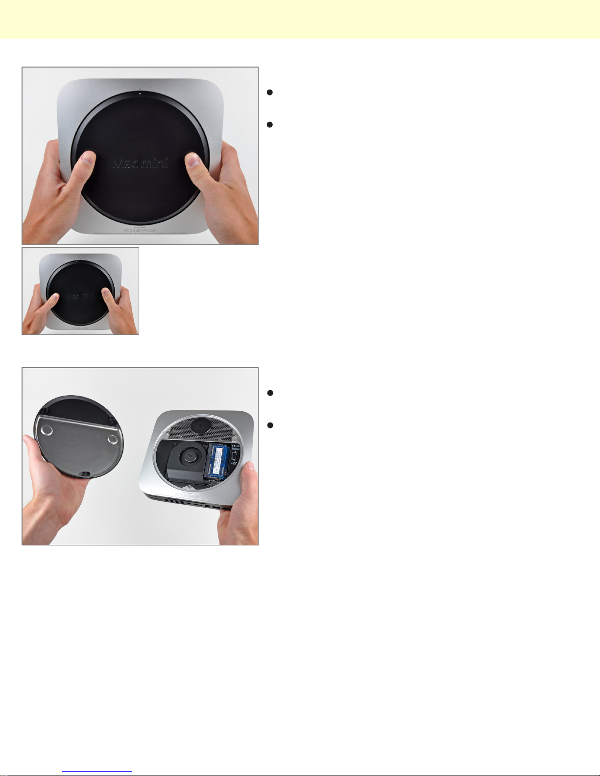
Step 1 - Bottom Cover
Place your thumbs in the depressions cut into the
bottom cover.
Rotate the bottom cover counter-clockwise until the
white dot painted on the bottom cover is aligned with
the ring inscribed on the outer case.
Step 2
Tilt the mini enough to allow the bottom cover to fall
away from the outer case.
Remove the bottom cover and set it aside.
© 2010 iFixit — CC BY-NC-SA www.iFixit.com Page 2 of 14
Page 3
Installing Mac mini Model A1347 IR Sensor
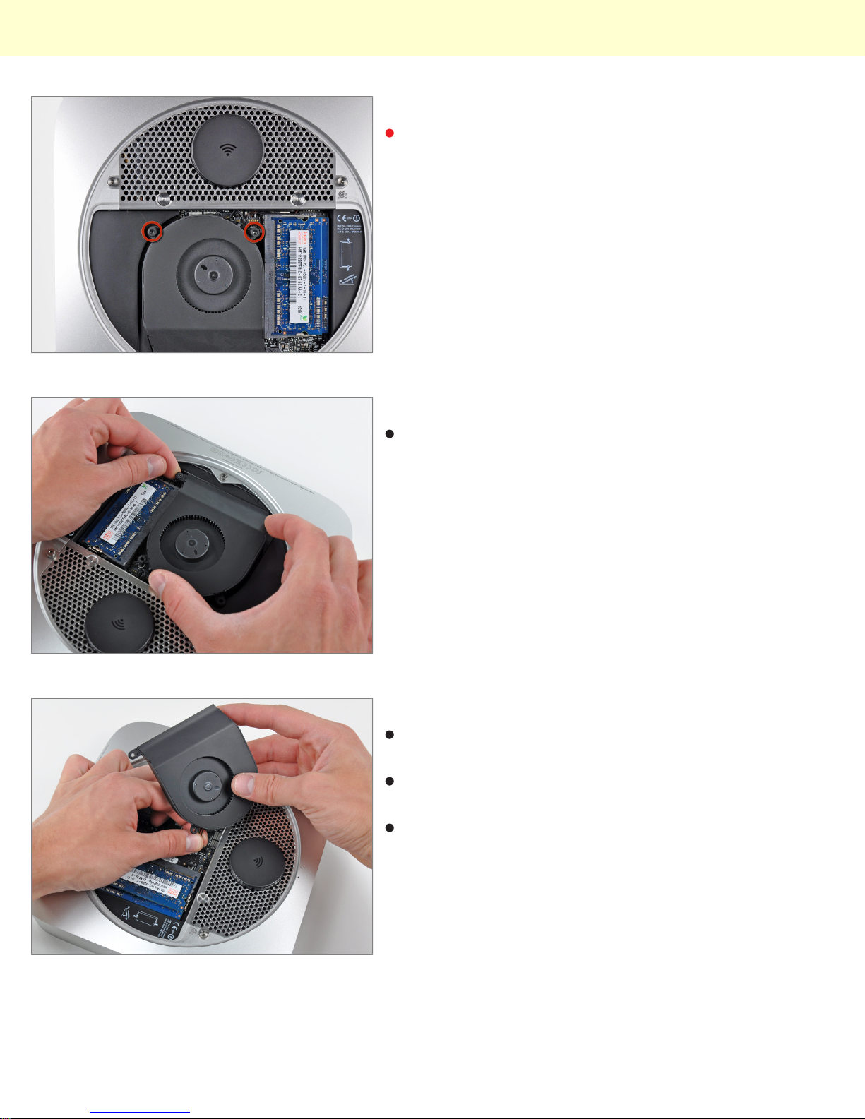
Step 3 - Fan
Remove the two 11.3 mm T6 Torx screws securing the
fan to the logic board near the antenna plate.
Step 4
Lift the ear of the fan nearest the RAM up off the
standoff secured to the outer case.
Step 5
Lift the fan out of the mini for enough clearance to
access its connector.
Carefully pull the fan cables upward to lift the fan
connector up out of its socket on the logic board.
Remove the fan.
© 2010 iFixit — CC BY-NC-SA www.iFixit.com Page 3 of 14
Page 4
Installing Mac mini Model A1347 IR Sensor
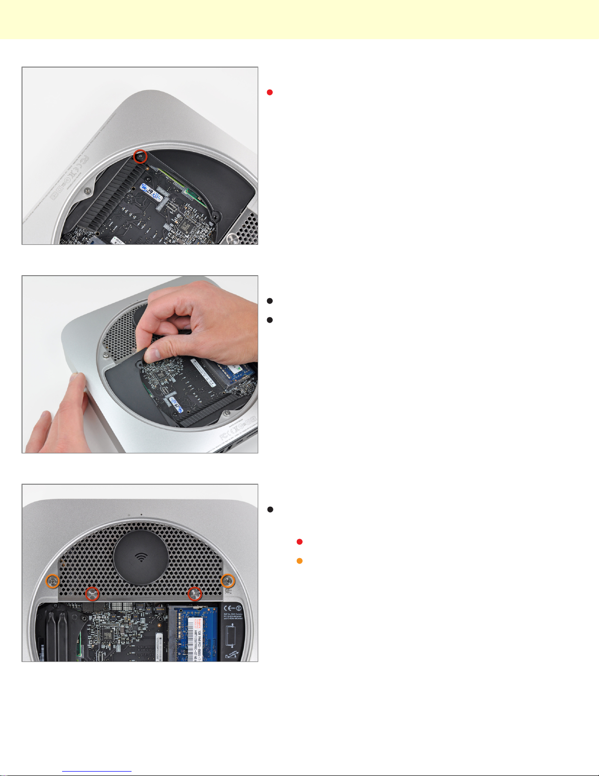
Step 6 - Cowling
Remove the single 3.5 mm T6 Torx screw securing the
cowling to the heat sink.
Step 7
Lift the cowling from the end nearest the antenna plate.
Rotate the cowling away from the outer case and
remove it from the mini.
Step 8 - Antenna Plate
Remove the following screws securing the antenna
plate to the mini:
Two 6.6 mm T8 Torx screws
Two 5.0 mm T8 Torx or 2.0 mm Hex screws
(either will work)
© 2010 iFixit — CC BY-NC-SA www.iFixit.com Page 4 of 14
Page 5
Installing Mac mini Model A1347 IR Sensor
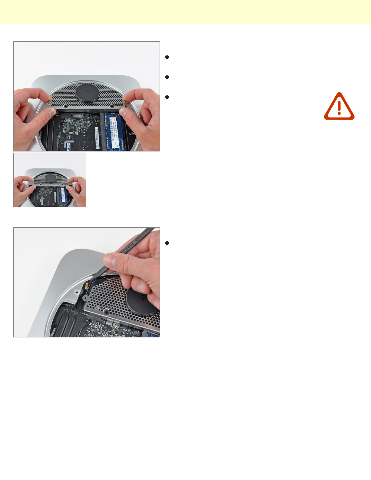
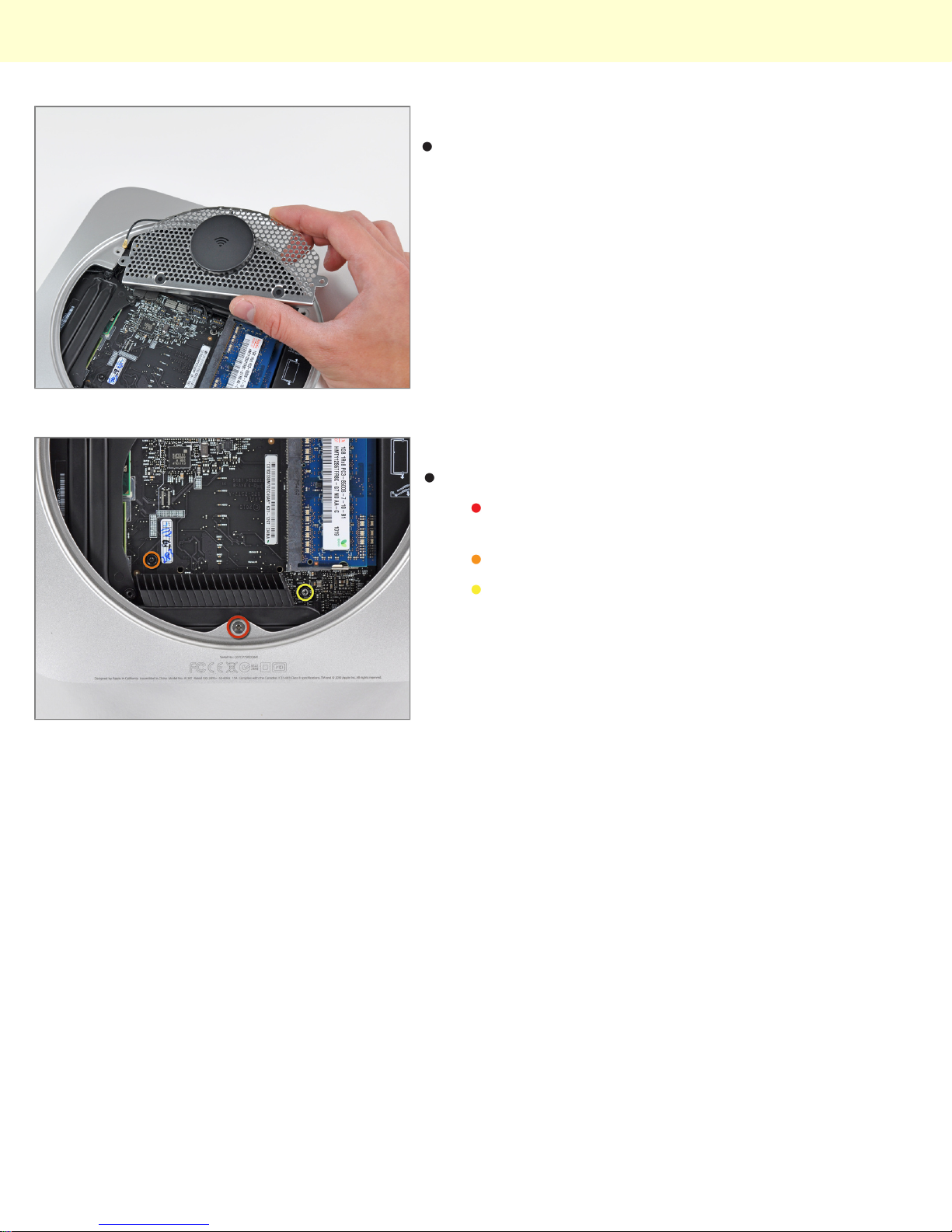
Step 9
Slightly lift the antenna plate from the end closest to the
RAM.
Carefully pull the antenna plate straight away from the
circular rim of the outer case.
Do not remove the antenna plate yet. It is
still attached to the AirPort/ Bluetooth board.
Step 10
Use the tip of a spudger to carefully pry the antenna
connector up off the AirPort/Bluetooth board.
© 2010 iFixit — CC BY-NC-SA www.iFixit.com Page 5 of 14
Page 6
Installing Mac mini Model A1347 IR Sensor
Step 11
Remove the antenna plate from the mini.
Step 12 - Logic Board
Remove the following three screws:
One 5.0 mm T8 Torx or 2.0 mm Hex screw (either
will work)
One 16.2 mm T6 Torx screw
One 26 mm T6 Torx standoff
© 2010 iFixit — CC BY-NC-SA www.iFixit.com Page 6 of 14
Page 7
Installing Mac mini Model A1347 IR Sensor
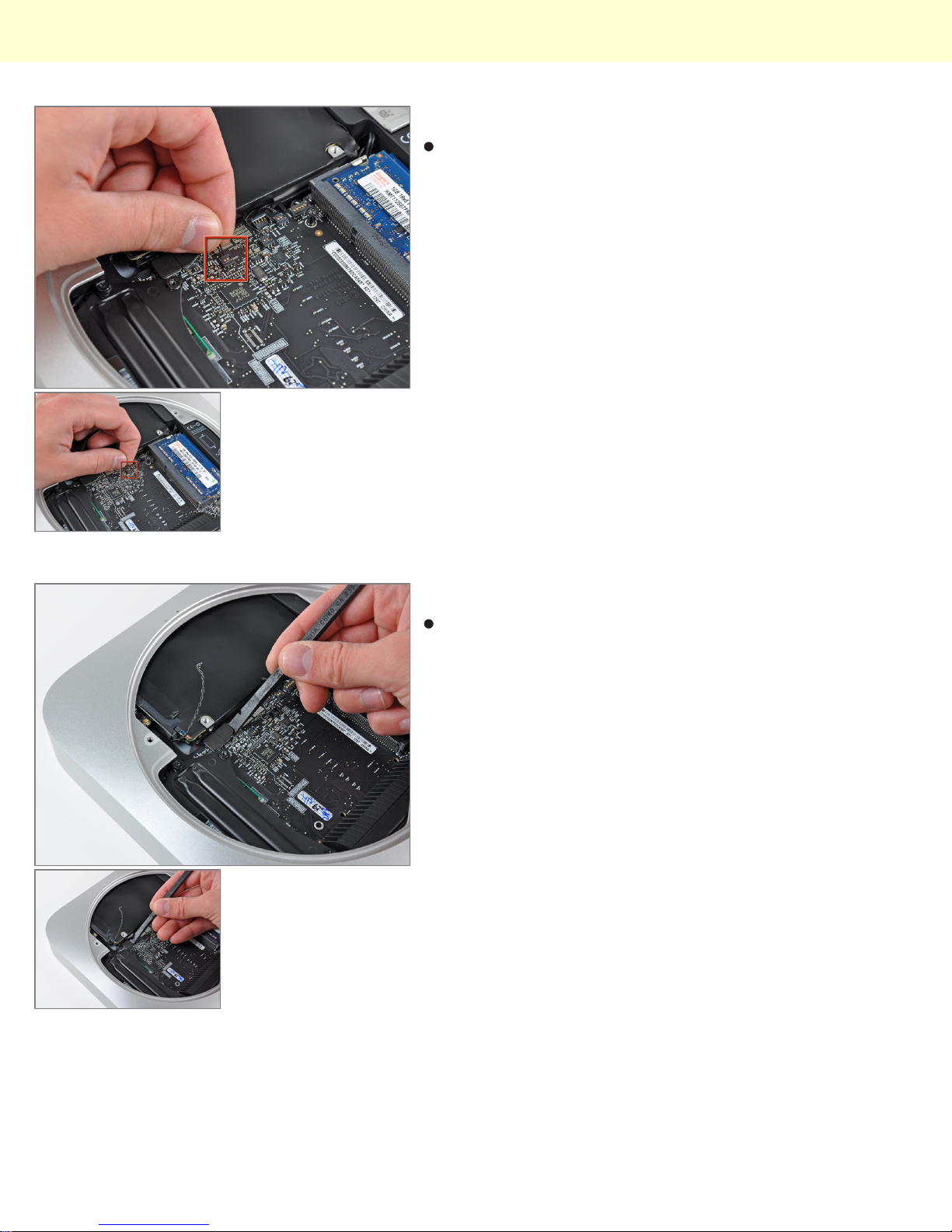
Step 13
Carefully pull the wires for both hard drive thermal
sensors upward to lift their connectors up and out of the
sockets on the logic board.
Step 14
Use the flat end of a spudger to pry both the hard drive
and optical drive connectors up out of their sockets on
the logic board.
© 2010 iFixit — CC BY-NC-SA www.iFixit.com Page 7 of 14
Page 8
Installing Mac mini Model A1347 IR Sensor
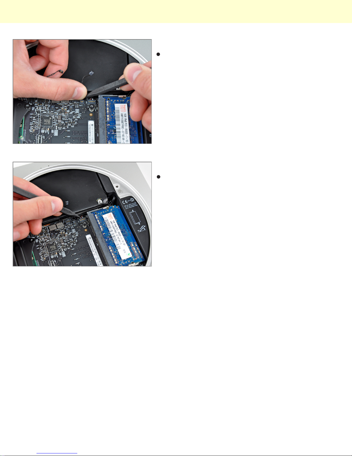
Step 15
To disconnect the optical drive thermal sensor, pinch its
cables between your thumb and a spudger and pry the
spudger upward to lift the connector up and out of its
socket on the logic board.
Step 16
Use the tip of a spudger to lift the IR sensor connector
up and out of its socket on the logic board.
© 2010 iFixit — CC BY-NC-SA www.iFixit.com Page 8 of 14
Page 9
Installing Mac mini Model A1347 IR Sensor
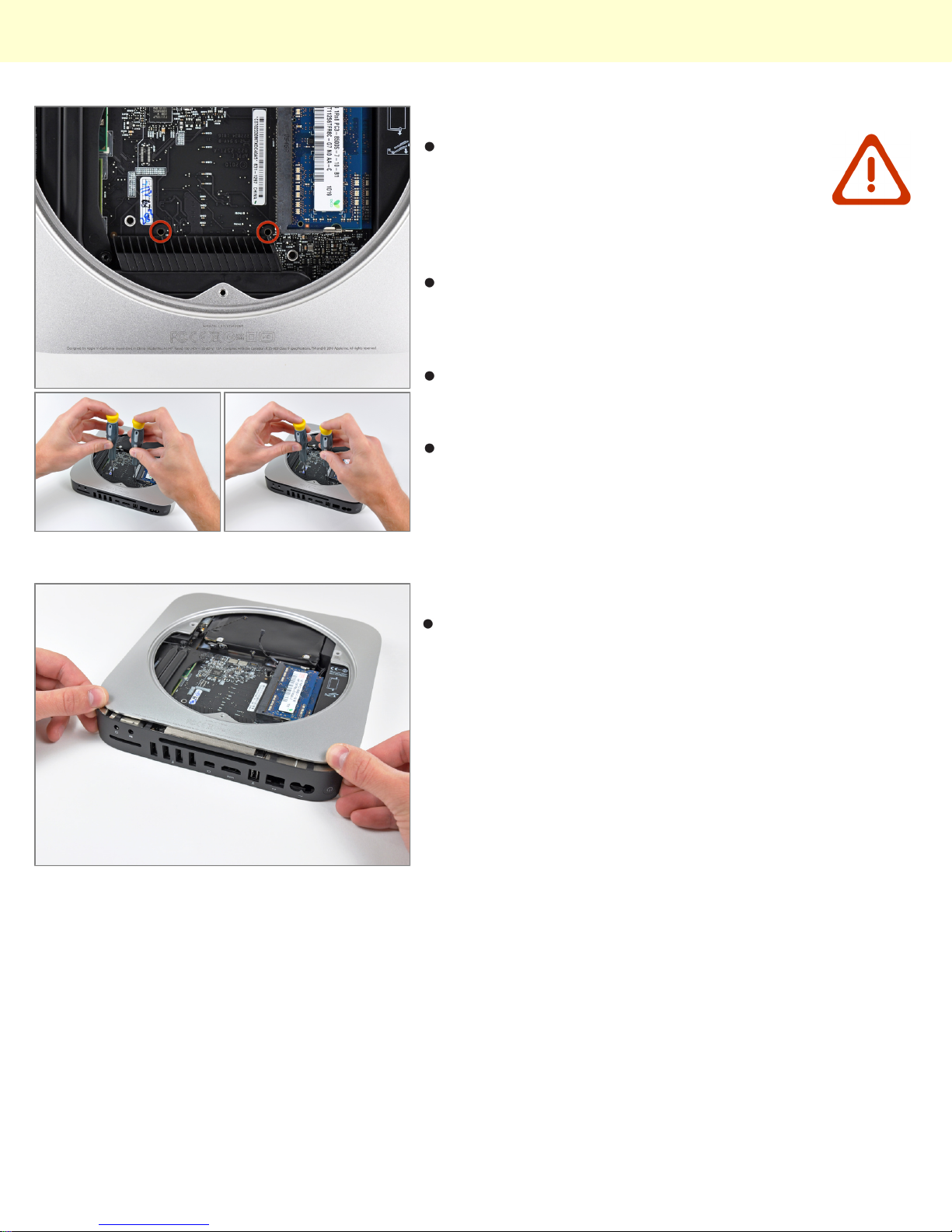
Step 17
To remove the logic board, two cylindrical
rods must be inserted into the holes
highlighted in red. Inserting instruments into
any logic board holes other than the ones
highlighted in red may destroy the logic
board.
Insert two tools having a maximum diameter of 2.5 mm
into the holes highlighted in red. Be sure they make
contact with the outer case below the logic board
before proceeding.
Carefully pry the tools toward the I/O board. The logic
board & I/O board assembly should slightly slide out of
the outer case.
Cease prying when the I/O board is visibly separated
from the outer case. Remove the two tools.
Step 18
Simultaneously push the two plastic clips on the far left
and right sides of the I/O board toward the middle of the
I/O board and pull the I/O board away from the outer
case.
© 2010 iFixit — CC BY-NC-SA www.iFixit.com Page 9 of 14
Page 10
Installing Mac mini Model A1347 IR Sensor
Step 19
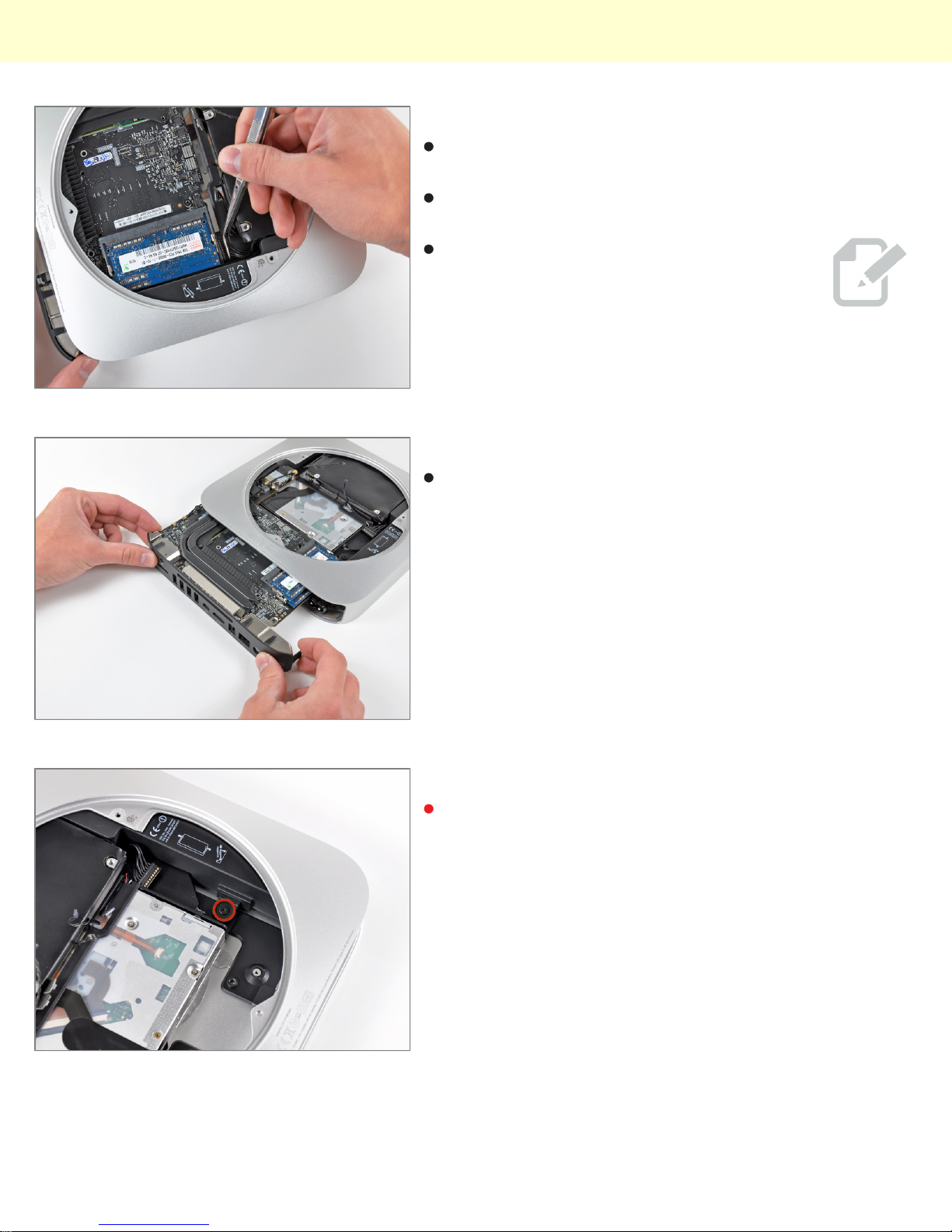
Pull the I/O board/logic board assembly out of the outer
case enough to access the power connector.
Use a pair of tweezers to disconnect the power cable
from the logic board.
Pull the power cable connector toward the
optical drive opening.
Step 20
Carefully slide the logic board assembly out of the mini,
minding any cables that may get caught.
Step 21 - Power Supply
Remove the 7.9 mm T6 Torx screw securing the power
supply and optical drive to the outer case.
© 2010 iFixit — CC BY-NC-SA www.iFixit.com Page 10 of 14
Page 11
Installing Mac mini Model A1347 IR Sensor
Step 22
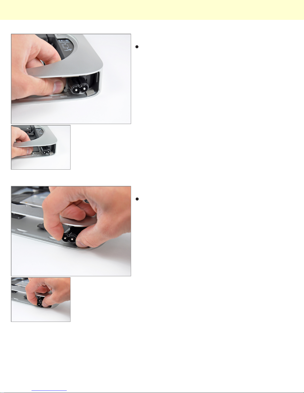
Pull the AC-In socket retainer away from the side of the
outer case and remove it from the mini.
Step 23
Rotate the AC-In connector 90 degrees counterclockwise.
© 2010 iFixit — CC BY-NC-SA www.iFixit.com Page 11 of 14
Page 12
Installing Mac mini Model A1347 IR Sensor
Step 24
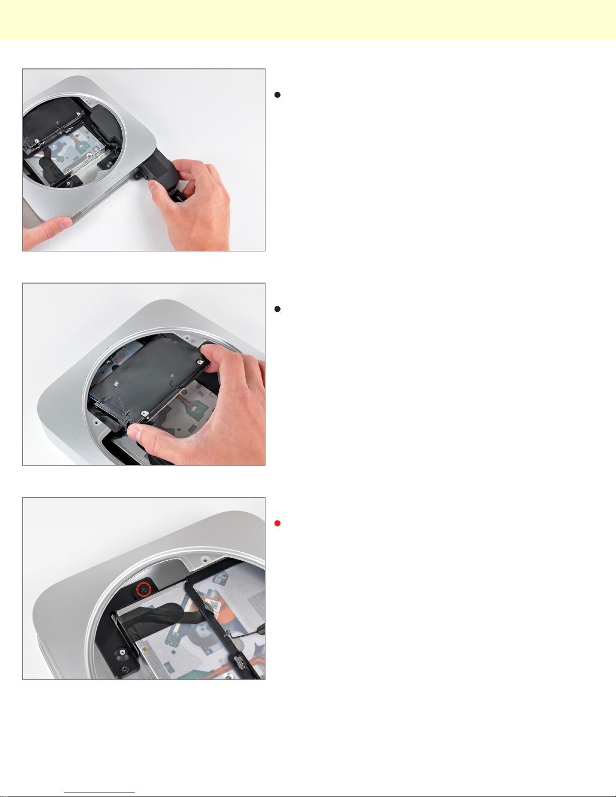
Slide the power supply out of the mini, minding any
cables that may get caught.
Step 25 - Optical Drive
Remove the hard drive from the mini, minding any
cables that may get caught.
Step 26
Remove the 7.9 mm T6 Torx screw securing the optical
drive to the outer case.
© 2010 iFixit — CC BY-NC-SA www.iFixit.com Page 12 of 14
Page 13
Installing Mac mini Model A1347 IR Sensor
Step 27
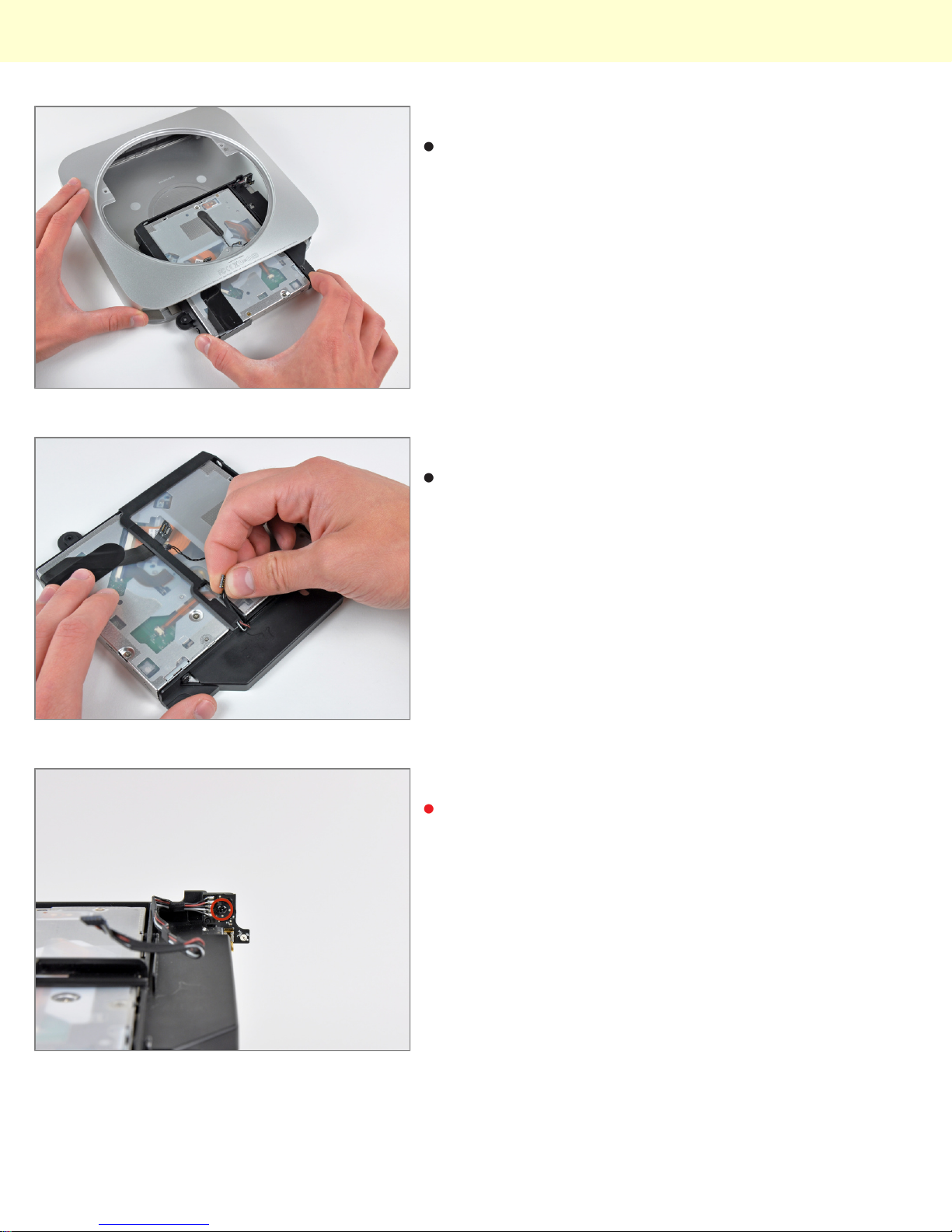
Slide the optical drive out of the outer case, minding
any cables that may get caught.
Step 28 - IR Sensor
Carefully de-route the IR sensor cables from the
channel in the optical drive bracket.
Step 29
Remove the 5 mm Phillips screw securing the IR board
to the optical drive bracket.
© 2010 iFixit — CC BY-NC-SA www.iFixit.com Page 13 of 14
Page 14
Installing Mac mini Model A1347 IR Sensor
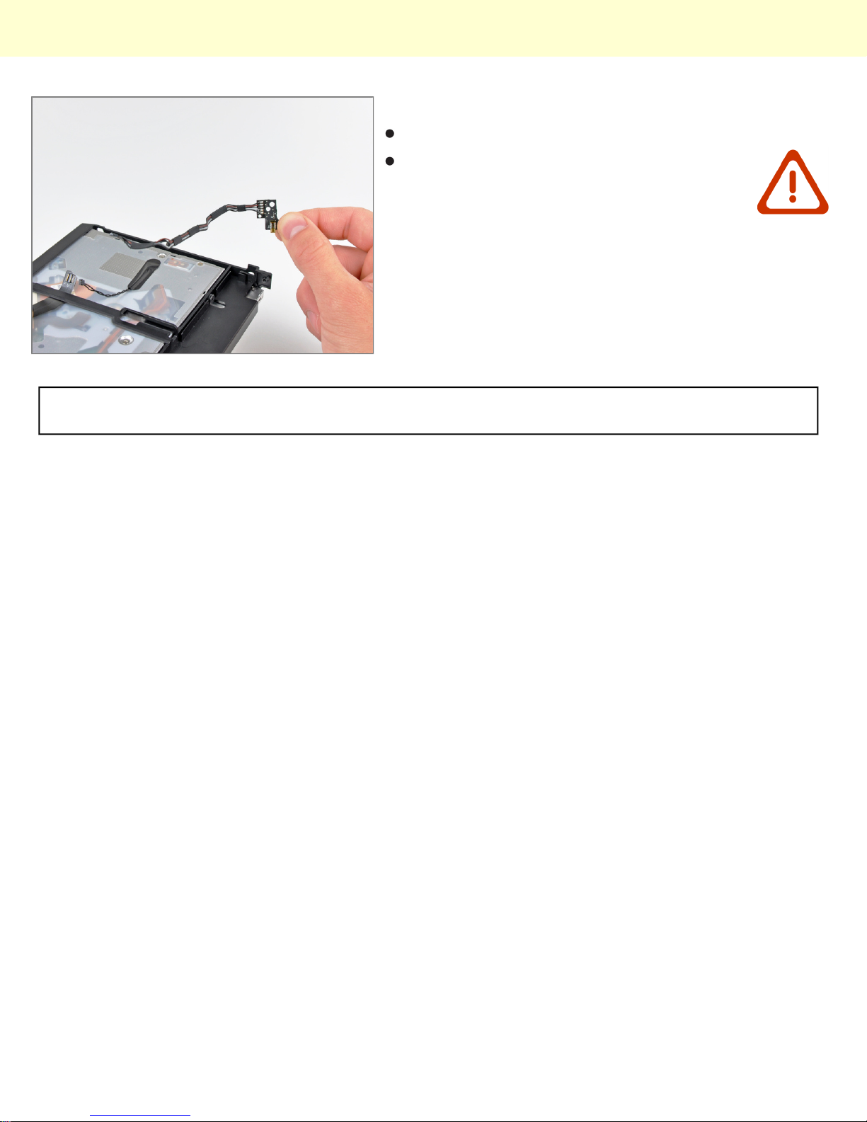
Step 30
Remove the IR sensor from the optical drive bracket.
Be careful when removing the IR board from
the optical drive bracket, as the lower plastic
positioning pin has the tendency to get
caught on the delicate IR board.
To reassemble your device, follow these instructions in reverse order.
© 2010 iFixit — CC BY-NC-SA www.iFixit.com Page 14 of 14
 Loading...