

IET Labs PRS-200 Operation Manual
♦ PRECISION INSTRUMENTS FOR TEST AND MEASUREMENT ♦
PRS-200 SERIES
High Precision
Manual or SCPI Programmable
Decade Resistance Substituters
(IEEE-488.2, RS232 or Ethernet)
Operation Manual
PRS200 IEEE.2 im/May 2015
IET LABS, INC.
Copyright 2015 IET Labs, Inc.
TEL: (516) 334-5959 • (800) 899-8438 • FAX: (516) 334-5988
www.ietlabs.com

♦ PRECISION INSTRUMENTS FOR TEST AND MEASUREMENT ♦
IET LABS, INC.
TEL: (516) 334-5959 • (800) 899-8438 • FAX: (516) 334-5988
www.ietlabs.com

WARRANTY
We warrant that this product is free from defects in material and workmanship and, when properly used,
will perform in accordance with applicable IET speci cations. If within one year after original shipment,
it is found not to meet this standard, it will be repaired or, at the option of IET, replaced at no charge when
returned to IET. Changes in this product not approved by IET or application of voltages or currents greater
than those allowed by the speci cations shall void this warranty. IET shall not be liable for any indirect,
special, or consequential damages, even if notice has been given to the possibility of such damages.
THIS WARRANTY IS IN LIEU OF ALL OTHER WARRANTIES, EXPRESSED OR IMPLIED,
INCLUDING BUT NOT LIMITED TO, ANY IMPLIED WARRANTY OF MERCHANTABILITY OR
FITNESS FOR ANY PARTICULAR PURPOSE.
i
WARNING
OBSERVE ALL SAFETY RULES
WHEN WORKING WITH HIGH VOLTAGES OR LINE VOLTAGES.
Dangerous voltages may be present inside this instrument. Do not open the case
Refer servicing to quali ed personnel
HIGH VOLTAGES MAY BE PRESENT AT THE TERMINALS OF THIS INSTRUMENT
WHENEVER HAZARDOUS VOLTAGES (> 45 V) ARE USED, TAKE ALL MEASURES TO
AVOID ACCIDENTAL CONTACT WITH ANY LIVE COMPONENTS.
USE MAXIMUM INSULATION AND MINIMIZE THE USE OF BARE
CONDUCTORS WHEN USING THIS INSTRUMENT.
WHEN WORKING WITH HIGH VOLTAGES, POST WARNING SIGNS AND
Use extreme caution when working with bare conductors or bus bars.
KEEP UNREQUIRED PERSONNEL SAFELY AWAY.
CAUTION
DO NOT APPLY ANY VOLTAGES OR CURRENTS TO THE TERMINALS OF THIS
INSTRUMENT IN EXCESS OF THE MAXIMUM LIMITS INDICATED ON
THE FRONT PANEL OR THE OPERATING GUIDE LABEL.
ii

CONTENTS
WARRANTY ................................................................................................ i
WARNING .................................................................................................. ii
CAUTION ................................................................................................... ii
Chapter 1: INTRODUCTION ..................................................................... 1
Chapter 2: SPECIFICATIONS ................................................................... 3
2.1 Model Conguration and specications ............................................................3
2.2 General specications ........................................................................................4
Chapter 3: OPERATION ............................................................................ 7
3.1 Initial inspection and setup ................................................................................7
3.2 Connection .........................................................................................................7
3.2.1 General Considerations ............................................................................7
3.2.2 Electrical Considerations .........................................................................7
3.2.3 Four-Wire Kelvin Lead Connections .......................................................7
3.2.4 Thermal emf Considerations....................................................................7
3.3 Dial Setting ........................................................................................................8
3.4 Environmental Conditions .................................................................................8
3.5 Local Operation .................................................................................................8
3.6 Remote Operation ..............................................................................................8
Chapter 4: ETHERNET OPTION ............................................................. 10
4.1 Ethernet Programming .....................................................................................10
4.2 Network Setup ............................................................................................................. 10
4.3 Ethernet Test Keyboard ........................................................................... ....................10
4.4 Network Conguration ................................................................................................ 11
4.5 Web Browser Conguration ........................................................................................ 11
4.6 VXI Conguration Utility ........................................................................................... 13
4.7 Resetting Default Network Settings ............................................................................ 15
4.8 PRS Programming ....................................................................................................... 15
Chapter 5: IEEE INTERFACE OPTION ................................................... 16
5.1 Introduction .......................................................................................... 16
5.2 Capabilities ........................................................................................... 16
5.3 Address Switch and Communications Settings .......................................... 16
5.4 IEEE Option Operation .......................................................................... 17
5.5 GPIB Test Keyboard ........................................................................................17
iii

Chapter 6: SERIAL INTERFACE OPTION .............................................. 18
6.1 Introduction .......................................................................................... 18
6.2 Capabilities ........................................................................................... 18
6.3 Signal Interface and Communications Settings ......................................... 18
6.4 Serial Option Operation .......................................................................... 18
6.5 Serial Test Keyboard ........................................................................................19
Chapter 7: PROGRAMMING ................................................................... 20
7.1 Introduction .......................................................................................... 20
7.2 Command String Structure ..................................................................... 20
7.3 Advanced Programming Software Driver ................................................. 21
Chapter 8: MAINTENANCE .................................................................... 24
8.1 Verication of Performance .................................................................... 24
8.2 Calibration Interval ................................................................................ 24
APPENDIX A: SCPI COMMAND REFERENCE ...................................... 25
APPENDIX B: IEEE.2 COMMON COMMANDS ...................................... 27
iv
PRS-200 Series
Chapter 1
INTRODUCTION
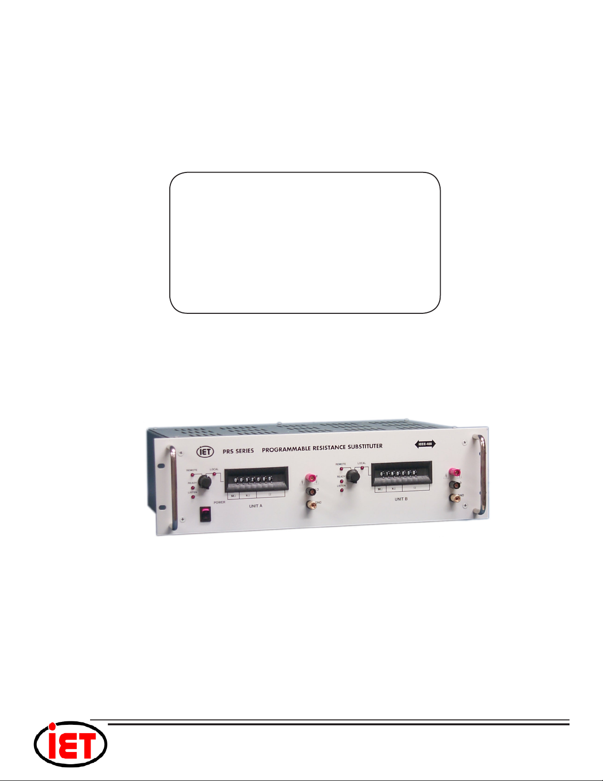
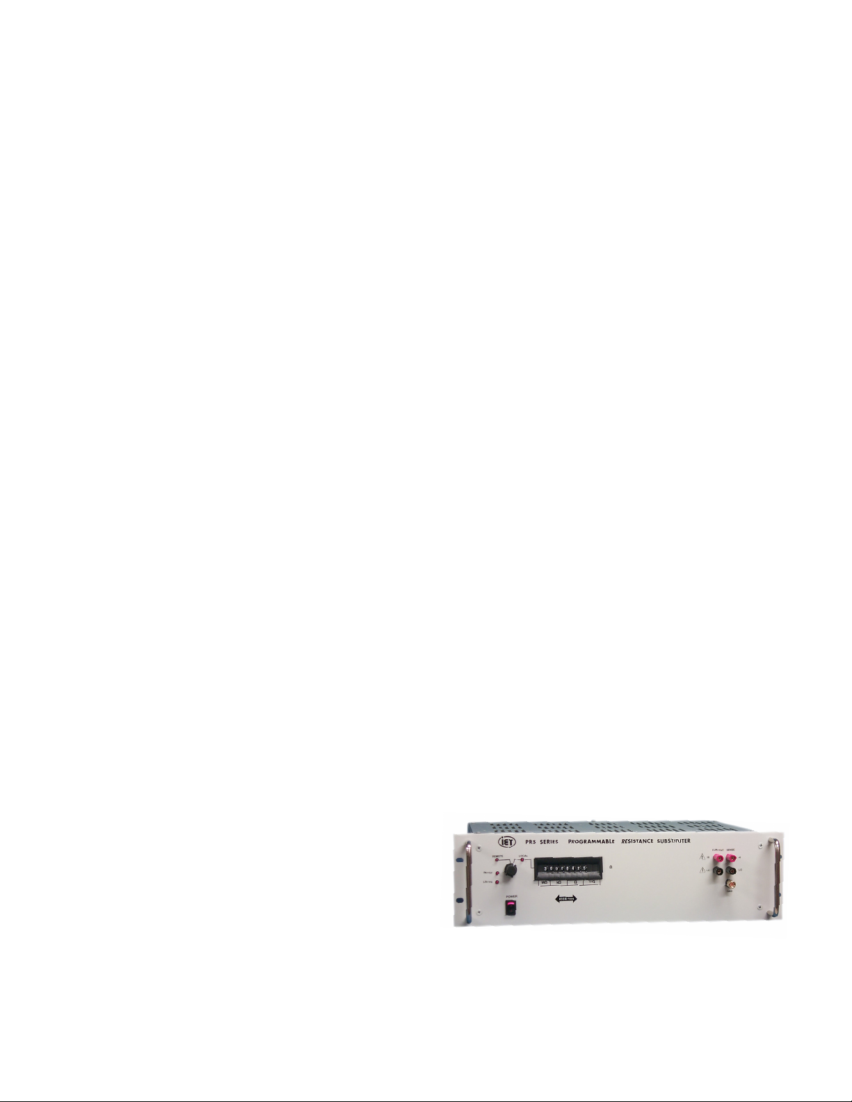
The PRS Series (Figure 1.1) is a broad
line of high precision manual and programmable decade substituters. They provide direct
resistance substitution as well as RTD (Resistance Temperature Detector) simulation, in a
wide selection of ranges, tolerances and ratings.
The PRS substituter is a precision resistance source with excellent characteristics of
stability, temperature coefcient, and power
coefcient. High dynamic ranges are available, starting as low as 1 mΩ, and extending
to as many as 10 decades. These features
combined with a low virtually constant “zero
resistance” make for very versatile instruments.
The PRS Series features two optional
special settings. An “open circuit” and a “short
circuit”. These modes are useful for obtaining
reproducible transitions between settings, i.e.
break-before-make or to short between settings. The “short circuit” setting also provides
a reduced zero resistance.
Operation is both local using convenient
direct-reading front panel thumbwheel switches, and remote with optional Ethernet, RS-232,
or IEEE-488 interfaces. Both can provide an
optional extra “10” position for each decade.
currents are passed through them. This is most
often the case when only minute test currents
are drawn by digital multimeters and other test
instruments. Contact resistance remains low
and repeatable.
High-quality gold-plated tellurium-copper
ve-way binding posts serve to minimize the
thermal emf effects, which would produce errors in dc resistance measurements. All other
conductors within the instrument, as well as the
solder employed contain no metals or junctions
that could contribute to thermal emf problems.
With a resolution as low as 1 mΩ and
a maximum available resistance of over 100
MΩ, the PRS-202 Series may be used for
exacting precision measurement applications
requiring high accuracy, good stability, and low
zero resistance. They are suited for automatic
and manual calibration and testing, simulation
of RTD’S, programmable loads, and many
other laboratory and industrial applications.
The PRS Series may be rack mounted
to serve as components in measurement and
control systems.
The PRS Series employs very low resistance, low thermal emf relays with gold-clad
silver-alloy contacts. A special design keeps
contact resistance to a minimum. The gold
plating keeps the silver contacts from becoming tarnished when unused, or when only low
INTRODUCTION
Figure 1.1: High Precision Manual or Programmable
Decade Resistance Substituter
1

PRS-200 Series
This page is intentionally left blank.
2
INTRODUCTION
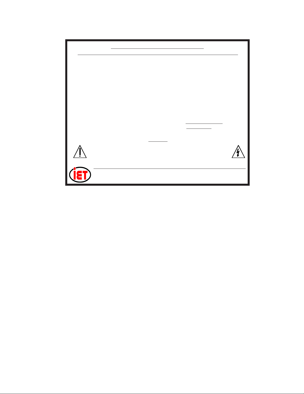
PRS SERIES OPERATING GUIDE
CONSULT INSTRUCTION MANUAL FOR PROPER INSTRUMENT OPERATION
Resistance Type: Metal film.
Range: 0 to 9,999,999 Ω, in 1 Ω steps.
Accuracy: ±(0.1% + 30 mΩ), after subtraction of zero setting resistance; traceable to NIST.
Zero Resistance: <450 mΩ, <410 mΩ, typical; <560 mΩ if OC (Open Circuit) option is pres-
ent; <20 mΩ, with SC (Short Circuit) option activated.
Maximum Load: 0.5 A, or 200 V (dc + peak ac), or 1 W/step, whichever applies rst.
Interface: IEEE-488.2-1987,SCPI 1994.0; front panel switch selects REMOTE or LOCAL
operation; “*IDN” for S/N, Model & REV; “CAL:DATe?” for last calibration date.
Ground: GND terminal on front panel is connected to both chassis and earth ground.
Operation: Unit should be allowed to stabilize for one hour. For maximum stability, allow unit
to warm-up over two hours and keep free from mechanical disturbances.
PRS-200 Series
POWER: 105-125 V, 50-60 Hz
FUSE: 0.25 A
WARNING
Observe all safety rules when working with high voltages or line voltages. Connect the shield to earth
ground in order to maintain the case at a safe voltage. Whenever hazardous voltages (>45 V) are used,
take all measures to avoid accidental contact with any live components: a) Use maximum insulation and
minimize the use of bare conductors. b) Remove power when adjusting switches. c) Post warning signs
and keep personnel safely away.
MODEL: PRS-201-1W-IEEE.2
SN: G2-XXXXXXX
IET LABS, INC. • Long Island, NY • info@ietlabs.com • (516) 334-5959 • (800) 899-8438
CAGE CODE: 62015 www.ietlabs.com
PRSBLBL/p27/PRS201-1W-IEEE.2/05-15
FIGURE 2.1 Typical OPERATING GUIDE Afxed to Unit
(Please see label afxed to your unit)
OPERATION
5

PRS-200 Series
Chapter 3
OPERATION
The GND terminal on all models is con-
nected to the case and to earth and chassis
grounds. This may be used as a shield terminal.
3.2.2 Electrical Considerations
The performance of the PRS is directly
affected by the quality of the connection to the
system under test. This is particularly true with
the precision series models having higher-accuracy and/or lower-impedance decades.
For optimum performance, contact resistance should be kept to a minimum by using
the most substantial mating connection possible, and by assuring that the connection is well
secured to the binding posts.
3.2.3 Four-Wire Kelvin Lead Connec-
tions
4-wire Kelvin leads minimize the effects
of contact resistance and approach ideal performance. The CURRENT and SENSE HI/
LO terminal pairs may be shorted together to
provide a 2-terminal connection in instances
where high accuracy is not a concern.
3.1 Initial inspection and setup
This instrument was tested and carefully
inspected before shipment. It should be in
proper electrical and mechanical order upon
receipt.
An OPERATING GUIDE is attached
to the case of the instrument to provide ready
reference to specications.
Mount the unit in a standard 19” rack if
the rack mount option is specied.
3.2 Connection
3.2.1 General Considerations
The PRS Series Decade unit is built in
3-terminal or 5-terminal versions. The binding
posts are standard laboratory type and readily
accept banana plugs, telephone tips, spade lugs,
alligator clips, and bare wire. Binding posts
are located on the front panel of the instrument
unless specically ordered with a Rear Output
option.
3.2.4 Thermal emf Considerations
The PRS Series uses high-quality, lowemf components. Thermal emf is primarily
attributable to the temperature difference
between the leads of the relay and the contacts
when temperature is applied to the coil. This
emf is of the order of 5 µV per relay, but is not
usually additive. The typical worst case is <15
µV.
6
The 3-terminal version posts are labeled
HI, LO, and GND. The HI and LO terminals
are connected to the ends of the internal imped-
ance being set.
5-terminal models provide four Kelvin
terminals consisting of a CURRENT and a
SENSE pair, each labeled HI and LO. These
minimize contact resistance.
OPERATION
 Loading...