

Page 1
♦ PRECISION INSTRUMENTS FOR TEST AND MEASUREMENT ♦
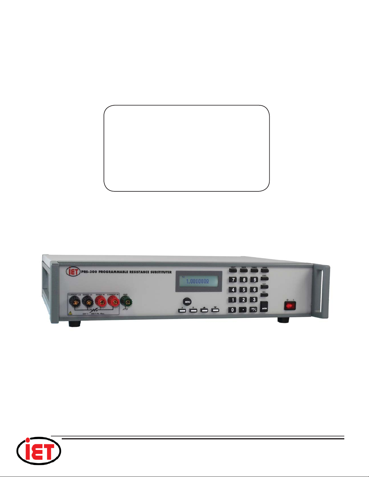
PRS-300 SERIES
Programmable
Decade Resistance Substituters
(IEEE-488.2, Ethernet and USB)
Operation Manual
IET LABS, INC.
TEL: (516) 334-5959 • (800) 899-8438 • FAX: (516) 334-5988
www.ietlabs.com
Page 2

IET LABS, INC.
TEL: (516) 334-5959 • (800) 899-8438 • FAX: (516) 334-5988
www.ietlabs.com
Page 3
♦ PRECISION INSTRUMENTS FOR TEST AND MEASUREMENT ♦
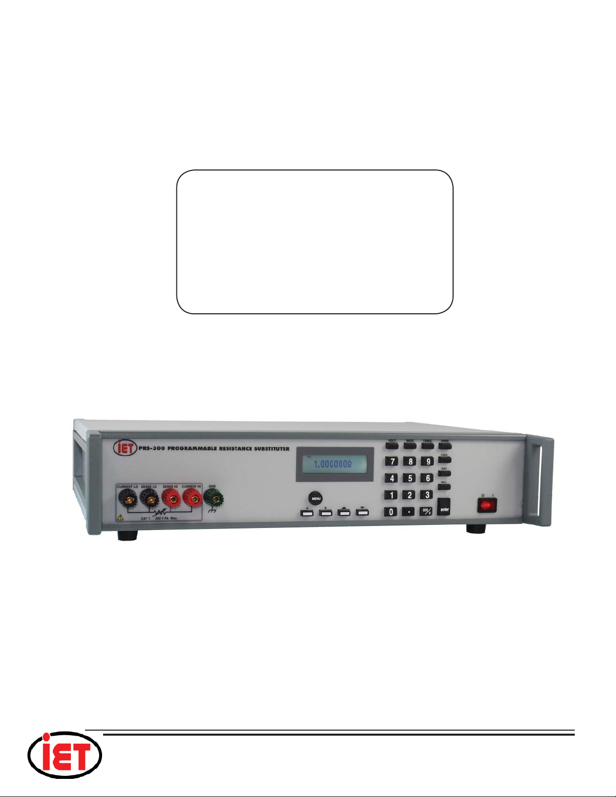
PRS-300 SERIES
Programmable
Decade Resistance Substituters
(IEEE-488.2, Ethernet and USB)
Operation Manual
PRS-300 IM / June 2018
IET LABS, INC.
Copyright © 2017 IET Labs, Inc.
TEL: (516) 334-5959 • (800) 899-8438 • FAX: (516) 334-5988
www.ietlabs.com
Page 4

♦ PRECISION INSTRUMENTS FOR TEST AND MEASUREMENT ♦
IET LABS, INC.
TEL: (516) 334-5959 • (800) 899-8438 • FAX: (516) 334-5988
www.ietlabs.com
Page 5

WARRANTY
We warrant that this product is free from defects in material and workmanship and, when properly used,
will perform in accordance with applicable IET specifi cations. If within one year after original shipment,
it is found not to meet this standard, it will be repaired or, at the option of IET, replaced at no charge when
returned to IET. Changes in this product not approved by IET or application of voltages or currents greater
than those allowed by the specifi cations shall void this warranty. IET shall not be liable for any indirect,
special, or consequential damages, even if notice has been given to the possibility of such damages.
THIS WARRANTY IS IN LIEU OF ALL OTHER WARRANTIES, EXPRESSED OR IMPLIED,
INCLUDING BUT NOT LIMITED TO, ANY IMPLIED WARRANTY OF MERCHANTABILITY OR
FITNESS FOR ANY PARTICULAR PURPOSE.
Page 6

WARNING
OBSERVE ALL SAFETY RULES
WHEN WORKING WITH HIGH VOLTAGES OR LINE VOLTAGES.
Dangerous voltages may be present inside this instrument. Do not open the case
Refer servicing to qualifi ed personnel
HIGH VOLTAGES MAY BE PRESENT AT THE TERMINALS OF THIS INSTRUMENT
WHENEVER HAZARDOUS VOLTAGES (> 45 V) ARE USED, TAKE ALL MEASURES TO
AVOID ACCIDENTAL CONTACT WITH ANY LIVE COMPONENTS.
USE MAXIMUM INSULATION AND MINIMIZE THE USE OF BARE
CONDUCTORS WHEN USING THIS INSTRUMENT.
WHEN WORKING WITH HIGH VOLTAGES, POST WARNING SIGNS AND
Use extreme caution when working with bare conductors or bus bars.
KEEP UNREQUIRED PERSONNEL SAFELY AWAY.
CAUTION
DO NOT APPLY ANY VOLTAGES OR CURRENTS TO THE TERMINALS OF THIS
INSTRUMENT IN EXCESS OF THE MAXIMUM LIMITS INDICATED ON
THE FRONT PANEL OR THE OPERATING GUIDE LABEL.
Page 7

SAFETY SUMMARY
The following general safety precautions must be observed during all phases of operation, service,
and repair of this instrument. Failure to comply with these precautions or with specifi c WARNINGS
elsewhere in this manual may impair the protection provided by the equipment. Such noncompliance
would also violate safety standards of design, manufacture, and intended use of the instrument.
IET Labs assumes no liability for the customer’s failure to comply with these precautions.
The PRS-300 complies with INSTALLATION CATEGORY I as well as POLLUTION DEGREE 2
in IEC61010-1.
If an instrument is marked CAT I (IEC Measurement Category I), or it is not marked with a
measurement category, its measurement terminals must not be connected to line-voltage mains.
The PRS-300 is an indoor use product.
DANGEROUS PROCEDURE WARNINGS
Comply with all WARNINGS - Procedures throughout in this manual prevent you from potential
hazard. These instructions contained in the warnings must be followed.
BEFORE APPLYING POWER
Verify that all safety precautions are taken. Make all connections to the instrument before applying
power. Note the instrument’s external markings described under “Safety Symbols”.
GROUND THE INSTRUMENT
This is a Safety Class I instrument. To minimize shock hazard, the instrument chassis and cabinet
must be connected to an electrical ground. The power terminal and the power cable must meet
International Electrotechnical Commission (IEC) safety standards.
CAUTION
• DO NOT Operate in an Explosive Atmosphere
• Do not operate the instrument in the presence of infl ammable gasses or fumes
• Operation of any electrical instrument in such an environment clearly constitutes a safety
hazard
• Use Caution around live circuits
• Operators must not remove instrument covers
• Component replacement and internal adjustments must be made by qualifi ed maintenance
personnel only
• DO NOT substitute parts or modify the instrument
To avoid the danger of introducing additional hazards, do not install substitute parts or perform
unauthorized modifi cations to the instrument.
Return the instrument to an IET Labs for service and repair to ensure that safety features are maintained
in operational condition.
Page 8
Safety Symbols
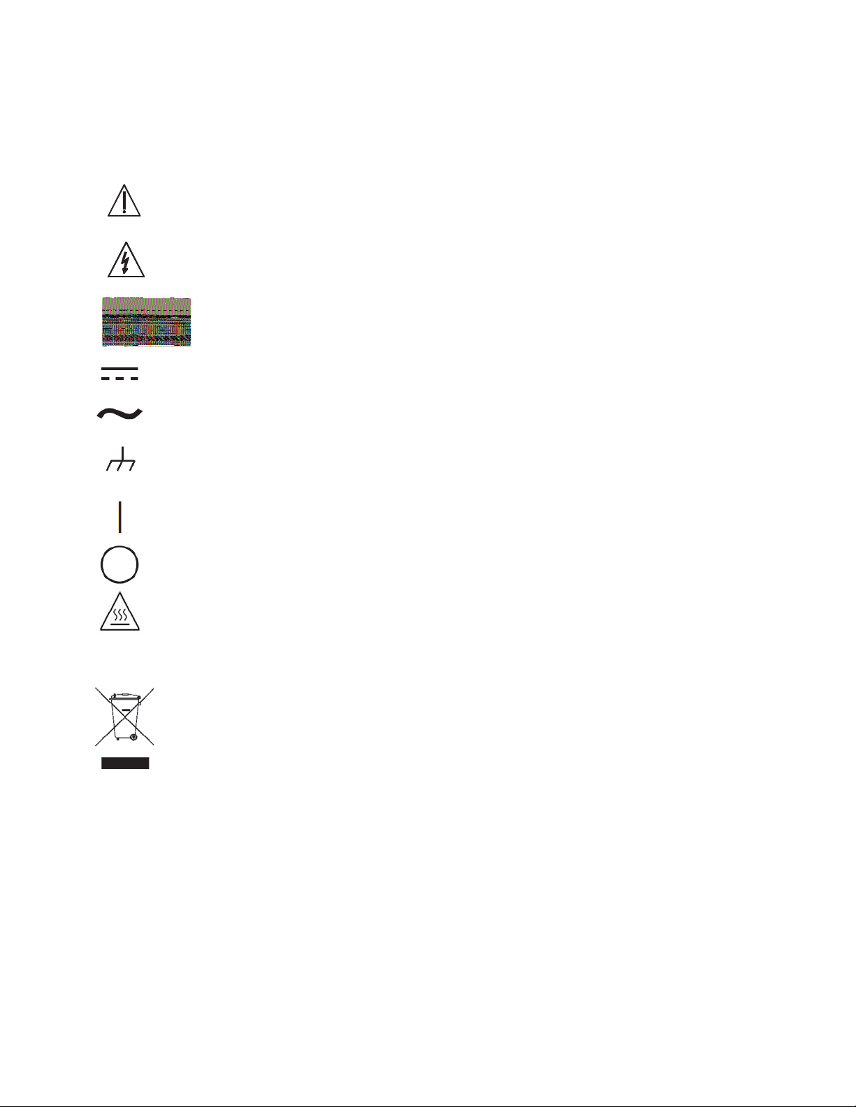
General defi nitions of safety symbols used on the instrument or in manuals are listed below.
Caution symbol: the product is marked with this symbol when it is necessary for the user to
refer to the instruction manual.
Hazardous voltage symbol: the product is marked with this symbol when high voltage maybe
present on the product and an electrical shock hazard can exist.
Indicates the grounding protect terminal, which is used to prevent electric shock from the
leakage on chassis. The ground terminal must connect to earth before using the product
Direct current.
Alternating current.
Frame or chassis terminal. A connection to the frame (chassis) of the equipment which
normally includes all exposed metal structures.
On supply.
Disposal
Off supply.
Hot surface. Avoid contact. Surfaces are hot and may cause personal injury if touched.
Waste Electrical and Electronic Equipment (WEEE) Directive 2002/96/EC
This product complies with the WEEE Directive (2002/96/EC) marking requirements.
The affi xed label indicates that you must not discard this electrical/ electronic product in domestic
household waste.
Product Category: With reference to the equipment types in the WEEE directive Annex 1, this product
is classifi ed as a “Monitoring and Control instrumentation” product.
Do not dispose of electrical appliances as unsorted municipal waste, use separate collection facilities.
Contact your local government for information regarding the collection systems available. If electrical
appliances are disposed of in landfi lls or dumps, hazardous substances can leak into the groundwater
and get into the food chain, damaging your health and well-being.
When replacing old appliances with new one, the retailer is legally obligated to take back your old appliances for disposal.
Page 9

PRS-300 Series
CONTENTS
WARRANTY ........................................................................................................... i
WARNING .............................................................................................................ii
CAUTION ..............................................................................................................ii
CONTENTS .......................................................................................................... iii
FIGURES .............................................................................................................. iv
TABLES ............................................................................................................... iv
Chapter 1: INTRODUCTION ................................................................................ 1
Chapter 2: SPECIFICATIONS .............................................................................. 3
2.1 Specifi cations .................................................................................................................3
2.2 General Specifi cations and Stability ..............................................................................4
2.2 Typical Label ..................................................................................................................5
Chapter 3: OPERATION ....................................................................................... 6
3.1 Initial inspection and setup ............................................................................................6
3.2 Connection .....................................................................................................................6
3.2.1 General Considerations ........................................................................................6
3.2.2 Electrical Considerations ......................................................................................6
3.3 Condensed Operating Instructions .................................................................................6
3.4 Menu Structure ...............................................................................................................7
3.4.1 Main Menu ...........................................................................................................8
3.4.2 Setting a Resistance Value ....................................................................................8
3.4.3 Menu Button .........................................................................................................8
3.4.4 Standard Values Screen ........................................................................................8
3.4.5 TABLE Key ..........................................................................................................9
3.4.6 Increment INCR Key ............................................................................................9
3.4.7 OPEN Key ............................................................................................................9
3.4.8 STO,RCL Keys ...................................................................................................10
3.4.9 VOLT Key ..........................................................................................................10
3.4.10 2 and 4 Wire Connections ................................................................................10
3.4.11 Thermal emf Considerations ............................................................................10
3.4.12 Environmental Conditions ................................................................................11
3.4.13 Remote Operation .............................................................................................11
Chapter 4: USB Interface .................................................................................. 12
4.1 Introduction ..................................................................................................................12
4.2 Capabilities ..................................................................................................................12
4.3 USB Operation .............................................................................................................12
Chapter 5: ETHERNET INTERFACE OPTION ................................................... 14
5.1 Ethernet Programming .................................................................................................14
5.2 Network Setup .............................................................................................................14
5.3 Ethernet Test Keyboard ................................................................................................14
5.4 Network Confi guration ................................................................................................15
iiTable of Contents
Page 10

5.5 Web Browser Confi guration .........................................................................................15
5.6 VXI Confi guration Utility ............................................................................................17
5.7 Resetting Default Network Settings .............................................................................19
5.8 PRS Programming .......................................................................................................19
Chapter 6: IEEE INTERFACE OPTION ..............................................................20
6.1 Introduction ..................................................................................................................20
6.2 Capabilities ..................................................................................................................20
6.3 Address Switch and Communications Settings ............................................................20
6.4 IEEE Option Operation ................................................................................................20
Chapter 7: PROGRAMMING ................................................................... 22
7.1 Introduction ......................................................................................... 22
Chapter 8: MAINTENANCE .................................................................... 23
8.1 Verifi cation of Performance .................................................................... 23
8.1.1 Calibration Interval ........................................................................ 23
8.1.2 General Considerations .................................................................. 23
8.1.3 Calibration Procedure .................................................................... 23
8.1.4 Adjustment of Internal Resistors ..................................................... 23
Chapter 9: PRS-DMM Self Adjusting Software .................................... 25
9.1 PRS-DMM Self Adjusting Softtware ....................................................... 25
9.1.1 PRS-DMM Self Adjusting Software Overview ................................. 25
9.1.2 General Requirements .................................................................... 25
9.1.3 Software Installation ...................................................................... 25
9.1.3 Connection Between DMM and PRS-300 ........................................ 25
9.1.3 PC Connection Between DMM and PRS-300 ................................... 25
9.2 PRS-DMM Main Screen ........................................................................ 26
9.2.1 PRS-DMM Main Screen Operation ................................................. 26
9.3 PRS-DMM Settings ............................................................................... 26
9.3.1 PRS-DMM Settings Screen ............................................................ 26
9.3.2 PRS-DMM Settings ....................................................................... 26
9.3.3 Meter Settings ............................................................................... 27
9.3.4 Adjust PRS ................................................................................... 27
9.3.4 PRS-DMM Speed .......................................................................... 28
PRS-300 Series
APPENDIX A: SCPI COMMAND REFERENCE ...................................... 29
APPENDIX B: IEEE.2 COMMON COMMANDS ...................................... 33
iii Table of Contents
Page 11
PRS-300 Series
Chapter 1
INTRODUCTION
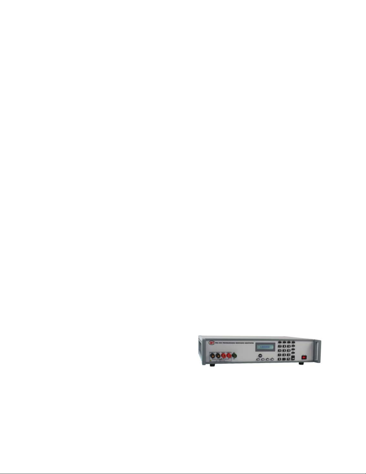
The PRS-300 (Figure 1.1) is a high
precision manual and programmable decade
substituter. The PRS-300 series provide direct
resistance substitution as well as RTD (Resistance Temperature Detector) simulation.
The PRS-300 substituter is a precision
resistance source with excellent characteristics
of stability, temperature coeffi cient, and power
coeffi cient. These features combined with a
low virtually constant “zero resistance” make
for very versatile instruments.
Operation is both local using convenient
display and keypad and remote standard USB
or optional Ethernet, and IEEE-488.2 interfaces. An RS-232 interface is also available upon
request.
The PRS-300 employs very low resistance, low thermal emf relays with gold-clad
silver-alloy contacts. A special design keeps
contact resistance to a minimum. The gold
plating keeps the silver contacts from becoming tarnished when unused, or when only low
currents are passed through them. This is most
often the case when only minute test currents
are drawn by digital multimeters and other test
instruments. Contact resistance remains low
and repeatable.
High-quality gold-plated tellurium-copper
fi ve-way binding posts serve to minimize the
thermal emf effects, which would produce errors in dc resistance measurements.
With a resolution as low as 1 Ω and a
maximum available resistance of 20 MΩ, the
PRS-300 may be used for exacting precision
measurement applications requiring high accuracy, good stability, and low zero resistance.
The PRS-300 is suited for automatic and
manual calibration and testing, simulation of
RTD’s, programmable loads, and many other
laboratory and industrial applications.
The PRS Series may be rack mounted
to serve as components in measurement and
control systems.
The PRS-300 (Figure 1.1) is part of the
PRS family of high precision manual and
programmable decade substituters. This series
Figure 1.1: High Precision Programmable Decade
Resistance Substituter
INTRODUCTION
1
Page 12

PRS-300 Series
offers a wide choice of ranges, power, voltage,
and accuracies for a wide variety of design and
production applications.
The PRS-300 uses a microcontroller design
to enhance the ease of use and calibration. It
provides direct resistance substitution as well
as RTD (Resistance Temperature Detector)
simulation. It allows for higher precision and
tighter tolerances.
The PRS-300 is a precision resistance source
with excellent characteristics of accuracy, stability, temperature coeffi cient, and power coef-
fi cient. It is direct reading without the need to
subtract “zero resistance.”
The PRS-300 offers the option of true 4-wire
Kelvin measurement for calibration applications and 2-wire mode for use in series as a
substitute resistor and for RTD applications.
The front panel display indicates the mode
selected: 2-wire or 4-wire.
internal calibration routine guides the user to
perform measurements using only a precision
ohmmeter and enter the measured values into
the PRS-300. No other standards are required.
IET Labs offers the PRS-DMM Self
Adjusting Software which works with the PRS300 and Fluke 8508A or Keysight 3458A to
automate this adjustment process and eliminate
the need for a technician to manual enter the
resistance values manually into the PRS-300
There are two pre-programmed RTD resistance
tables, and others may be added by the user.
The controller allows for other convenient programmed features.
The unique design makes adjustment of the
PRS-300 for calibration semiautomatic. An
2
INTRODUCTION
Page 13

PRS-300 Series
Chapter 2
SPECIFICATIONS
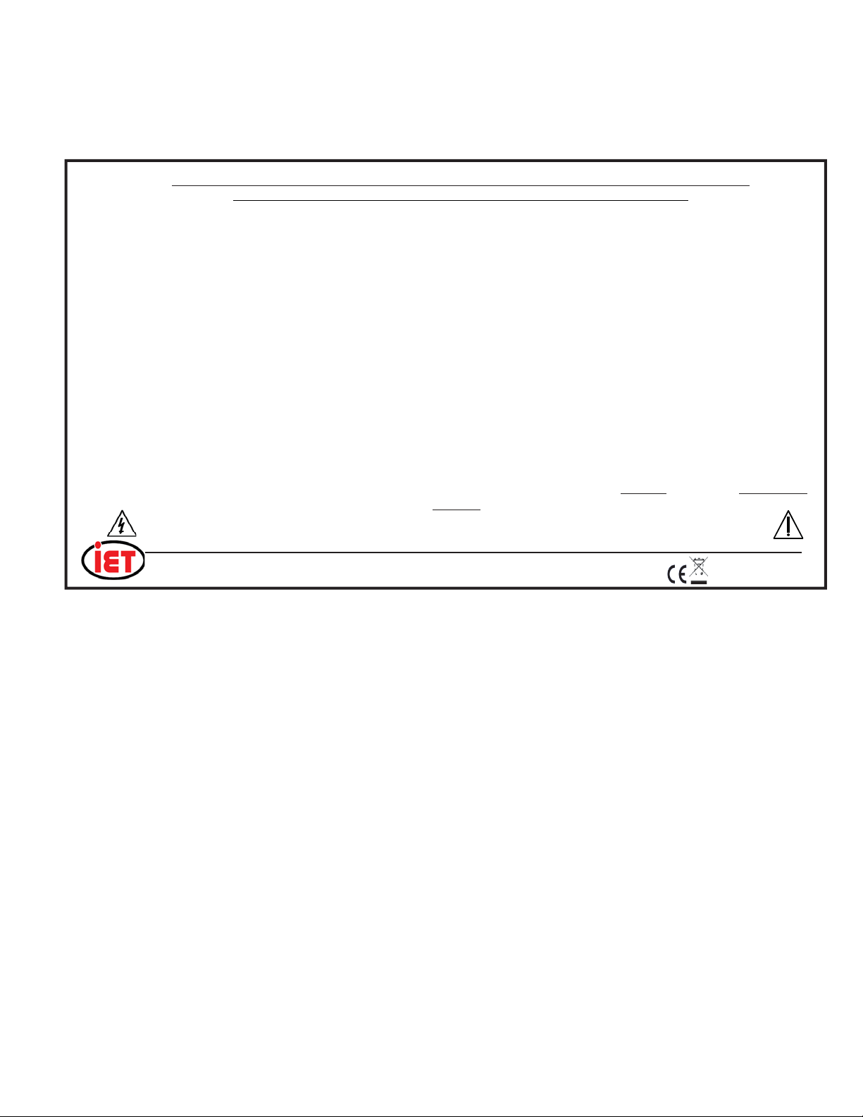
For convenience to the user, the pertinent
specifi cations are given in an OPERATING
GUIDE, shown typically in Figure 2.1, affi xed
to the case of the instrument.
2.1 Specifi cations
User interface:
Numeric keypad to enter resistance value with digital
display.
Accuracy: ±(70 ppm + 1 m) 2 and 4 Terminal at
23°C ±5°C Also see section 2.2
Minimum setting: 0.1
Resolution: 1 or 6 digits
Range: 0.1 - 20 M
Stability: See section 2.2
Thermal emf: < 15 V
Maximum Load: 2 A, 200 V (peak), 0.5 W whichever
applies fi rst
Resistors: Precision wire-wound and metal foil
TC of Resistors: < 1 ppm/°C for R4 and above
RTD Tables:
9 RTD tables can be entered into memory to allow
user selection of temperature and the correct value
of resistance will automatically be programmed.
PT-100 and PT-1000 tables for both Fahrenheit and
Celsius are pre-programmed into memory locations
1 to 4.
Adjustment:
Automatic adjustment procedure utilizing a high precision DMM eliminates the requirement for manual
trimming of resistors.
AC Frequency Response:
Residual Capacitance Terminals to GND: < 850 pF
Resistance Typical ac/dc difference @ 1 kHz
0.1 -10 k <100 ppm
10 - 100 k <200 ppm
100 k - 1 M <1%
Terminals:
Four low-emf, gold-plated, tellurium-cop per 5-way
bind ing posts are used for HI and LO ter mi nal pairs
for CUR RENT and SENSE. GND bind ing post is
con nect ed to the case, to the chassis ground and to
the earth ground.
Switching time: 15 ms Max for relay switch time
between values, typically < 1 ms.
< 20 ms to interpret command and switch via
ieee.488 interface
Power requirements:
90 - 264 Vac , 47 - 63 Hz. 30 Watts Max.
Environmental conditions:
Operating: 10°C to 40°C; <80% RH
Storage: -40°C to 70°C
Note: exposure to humidity >60% for extended
periods of time can cause the resistors to drift
some of which is reversible. See 2.2 for more
information
Dimensions:
Bench model: 43 cm W x 8.9 cm H x 33 cm D (17” x
3.5” x 13”) in front of panel: 3.8 cm (1.5”).
Weight:
Bench model: 5.5 kg (12 lb); weight specifi cations
are nominal.
Remote Control:
USB: USB Type B connector standard on rear panel
Remote Control Options:
IEEE:
GPIB standard 24 pin connector, conforms to IEEE-
488.2; SCPI 1994.0 command set; Hardware or
software confi gurable addressing range of 1 to 30.
Ethernet:
IEEE 802.3 compliant, Speeds 10 BaseT
(10 Mb/s) and 100 BaseT (100 Mb/s), IP Address
Static or DHCP, Factory setting 192.168.0.254 static
1 - 20 M <20%
SPECIFICATIONS
3
Page 14
PRS-300 Series
2.2 General Specifi cations and Stability
Warmup:
This unit utilizes custom designed low
thermal emf relays for high stability and lowlevel signal applications. This thermal voltage
is nominally less than 15 μV under laboratory
conditions. Please note that a change in this
thermal emf will give a false drift in resistance
as measured by a dc ohmmeter, since the ohmmeter will interpret this emf as an effective
resistance. The worst case such effective drift
after warm-up is less than ±25 ppm, primarily due to stabilization of this emf at the relay
contacts as settings are changed.
Unit should be allowed to stabilize for
one hour. For maximum stability, allow unit to
warm-up over two hours.
Recommended Calibration Interval:
Typical calibration interval 12 months.
Adjustment can easily be accomplished using IET’s PRS-DMM software. Adjusting the
PRS-300 can improve accuracy.
Environmental:
This product complies with the WEEE
Directive (2002/96/EC) marking
requirements. The affi xed label
indicates that you must not discard this
electrical/electronic product in domestic
household waste.
More information of the effects of humidity on foil resistors can be found at:
http://www.vishaypg.com/docs/63516/VFR_
TN110.pdf
Short-term Stability:
The PRS-300 was tested for extended periods of time. Based upon this testing the following stability information was determined.
These specifi cations apply for the PRS-300 in
4 terminal mode with shorting links removed
and without switching to another value.
Typical short-term stability without switching:
< ±(4 ppm + 100 ) / 10 minutes
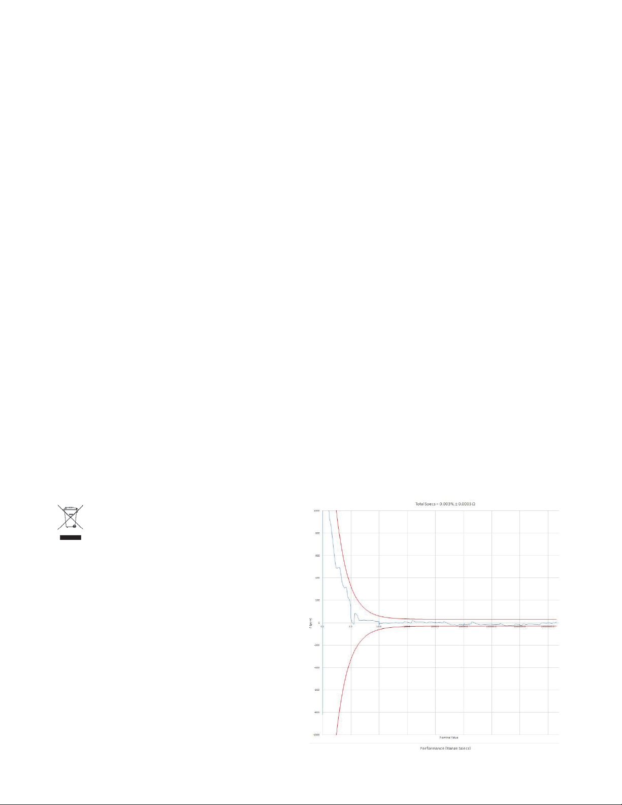
Typical 24 hr. Accuracy after Adjustment:
After performing an adjustment per 8.1.4
using a Fluke 8508A and then performing a
calibration verifi cation per 8.1.3 within 24
hours the typical accuracy is:
±(30 ppm + 300 ) for values less than 1 M
±60 ppm for values of 1 M and higher
See graph below for actual performance with 6
digit resolution across resistance range.
Product Category: With reference to the
equipment types in the WEEE Directive Annex
I, this product is classed as a “Monitoring and
Control instrumentation” product.
Effects of Humidity:
Exposure to humidity >60% for a periods
of weeks can cause the resistors to drift some
of which is reversible. It is recommended that
the PRS-300 be stored at humidities less than
50% to minimize this.
4
SPECIFICATIONS
Page 15
PRS-300 Series
PRS-300 PROGRAMMABLE DECADE RESISTANCE SUBSTITUTER
CONSULT INSTRUCTION MANUAL FOR PROPER INSTRUMENT OPERATION
Accuracy: ±(0.007% + 1 m) 2 and 4 Terminal at 23°C ±5°C
Minimum setting: 0.1
Resolution: 1 or 6 digits
Range: 0.1 - 20 M
Thermal emf: < 15 V
Maximum Load: 2 A, 200 V (peak), 0.5 W whichever applies fi rst
Resistors: Precision wire-wound and metal foil
RTD Tables:
9 RTD tables can be entered into memory to allow user selection of temperature
and the correct value of resistance will automatically be programmed.
PT-100 and PT-1000 tables for both Fahrenheit and Celsius are programmed
into memory locations 1 to 4.
Adjustment:
Automatic adjustment procedure utilizing a high precision DMM eliminates the
requirement for manual trimming of resistors.
Terminals:
Four low-emf, gold-plated, tellurium-cop per 5-way bind ing posts are used for HI
and LO ter mi nal pairs for CUR RENT and SENSE. GND bind ing post is con nect ed
to the case, to the chassis ground and to the earth ground.
Switching time: <1 second per change
Power requirements:
90 - 264 Vac , 47 - 63 Hz. 30 Watts Max.
Remote Control:
USB: Standard USB Type B connector on rear panel, uses FTDI driver
Remote Control Options:
IEEE: GPIB standard 24 pin connector, conforms to IEEE-488.2; SCPI 1994.0
command set; Hardware or software confi gurable addressing range of 1 to 30.
Ethernet: IEEE 802.3 compliant, Speeds 10 BaseT
(10 Mb/s) and 100 BaseT (100 Mb/s), IP Address Static or DHCP, Factory setting
192.168.0.254 static
MODEL: PRS-300 SN: B1-17341127
Observe all safety rules when working with high voltages or line voltages. Connect the (GND) terminal to earth ground in order to maintain the case at a safe voltage.
Whenever hazardous voltages (>45 V) are used, take all measures to avoid accidental contact with any live components: a) Use maximum insulation and minimize the use
IET LABS, INC.
CAGE CODE: 62015
of bare conductors. b) Remove power when adjusting switches. c) Post warning signs and keep personnel safely away.
• Long Island, New York
• Tel: (516) 334-5959 • Email: [email protected]
WARNING
www.ietlabs.com
PRS-300 Nov. 2016
FIGURE 2.1 Typical OPERATING GUIDE Affi xed to Unit
(Please see label affi xed to your unit)
SPECIFICATIONS
5
Page 16

PRS-300 Series
6
SPECIFICATIONS
Page 17

PRS-300 Series
Chapter 3
OPERATION
3.1 Initial inspection and setup
This instrument was tested and carefully
inspected before shipment. It should be in
proper electrical and mechanical order upon
receipt.
An OPERATING GUIDE is attached
to the case of the instrument to provide ready
reference to specifi cations.
Mount the unit in a standard 19” rack if
the rack mount option is specifi ed.
3.2 Connection
3.2.1 General Considerations
The PRS-300 Decade Resistor utilizes a
5-terminal connection. The binding posts are
standard laboratory type and readily accept
banana plugs, spade lugs, alligator clips, and
bare wire. Binding posts are located on the
front panel of the instrument unless specifi cally
ordered with a Rear Output option.
The Kelvin terminals consisting of a
CURRENT and a SENSE pair, each labeled
HI and LO. These minimize contact resis-
tance.
4 Wire connection the gold shorting links
must be removed on the binding posts of the
PRS-300 and the PRS-300 set to 4 Wire.
2 Wire connection the gold shorting links
must be used on the binding posts of the PRS300 and the PRS-300 set to 2 Wire.
See section 3.4.10 for more information
The GND terminal on all models is connected to the case and to earth and chassis
grounds. This may be used as a shield terminal.
3.2.2 Electrical Considerations
The performance of the PRS-300 is directly affected by the quality of the connection to
the system under test. This is particularly true
with the precision series models having higheraccuracy and/or lower-impedance decades.
For optimum performance, contact resistance should be kept to a minimum by using
the most substantial mating connection possible, and by assuring that the connection is well
secured to the binding posts.
3.3
Condensed Operating Instructions
1. Turn on the PRS-300 ON using POWER
SWITCH
2. Select a desired resistance value in one of
the following ways:
a) Enter a value using the number keys,
then press ENTER.
b) Press a Quick Value key (A – B) to
display a user-defi ned value or a factory
default value.
OPERATION
7
Page 18
PRS-300 Series
Default values are: A: 10 k B: 100
k
c) Press RCL then a number key (0 – 9)
to display a user-defi ned value or a fac-
tory default value.
Default values are: 0 - 100 1 - 1
k 2 - 2 k
3. To prevent possible damage to
the PRS-300, set the maximum
applied voltage by pressing VOLT,
entering the voltage on the keypad, then
pressing ENTER. (Default: 0.5 V)
The fi rmware sets the minimum selectable
resistance value so that the power does not
exceed 1 W. To ensure that the whole range
of resistances is selectable, VOLT setting
must be ≤1 V.
2
Rmin is limited to >V
, where V is the
VOLT setting.
4. Select 2-wire or 4-wire mode by pressing the MENU button, selecting CON-
FIGURE, pressing the “2” will change
between 2-wire and 4-wire modes
In 2-wire mode shorting links must be in-
stalled across high and low terminal pairs.
In 4-wire remove the shorting links.
5. Connect to the circuit or device under test.
To isolate the PRS-300 from the application,
press OPEN to open the circuit. To close the
circuit, press OPEN again.
3.4 Menu Structure
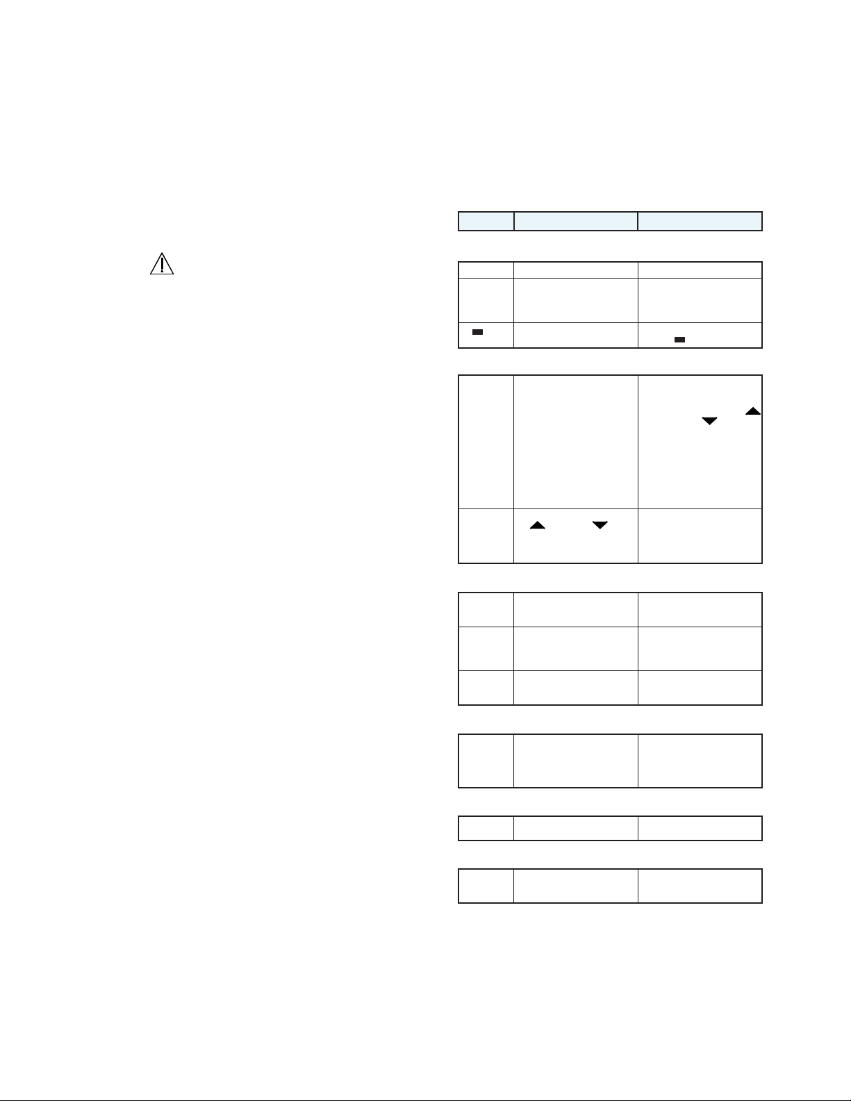
The main table below show menu structure of the PRS-300 and basic function of each
button and menu selection.
Key Description Function
Basic operation
enter enter button Sets resistance value
0-9, 000/(-) Used to enter numerical values. To select desired numerical
Options
MENU Displays the following submenu:
INCR Selects the increments for the
Storing and recalling resistance values
STO Stores a resistance value in
A, B Recalls a stored resistance
RCL Recalls a stored resistance
Limiting Current
VOLT Sets voltage to limit the current
Deletes the last character from
the display.
1. STANDARD VALUES
1: 1% STD VALUES
2: 5% STD VALUES
3: 10% STD VALUES
4: RATIOMETRIC
2. CONFIGURE
1: LCD CONTRAST
2: 2W / 4W MODE
3. CALIBRATE
4. VERSION
UP and DOWN keys
Default value: Ratiometric (0.8%
of displayed value)
memory locations A-D and 0-9.
value.
Default values:
A: 10 k B: 100 k
value from memory location 0-9.
in order to protect the PRS-300
from possible damage.
Default value: 0.5 V
value, press value as required.
(-) is used with tables for negative temperature
To delete the last character,
press .
Press MENU to select one of the
following:
1. STANDARD VALUES - selects increments for UP
and DOWN keys
2. CONFIGURE - allows user
to adjust display contrast
and change between 2-wire
and 4-wire modes
3. CALIBRATE - see Section 8
4. VERSION - Displays current fi rmware version and
release date.
To adjust increments:
1. Press INCR.
2. Enter desired increment
value on the keypad.
3. Press ENTER to save.
To store a value, press STO and
then press the desired location
button A-D or 0-9.
To change stored values:
1. Enter a resistance value
2. Press STO and then A, B
To recall a stored value, press
RCL, then press the desired
location button (0-9)
To adjust voltage:
1. Press VOLT.
2. Enter desired voltage on the
keypad.
3. Press ENTER to save.
Electrical Isolation
OPEN Isolates the connection terminals
Option: Simulating RTD’s and transducers
TABLE Loads up to 9 stored data
by establishing an open circuit.
tables for simulating RTD’s or
transducers.
8
To open the circuit, press OPEN.
To close, press OPEN again.
To select the desired table,
press TABLE to cycle through
the three options.
OPERATION
Page 19
PRS-300 Series
3.4.1 Main Display
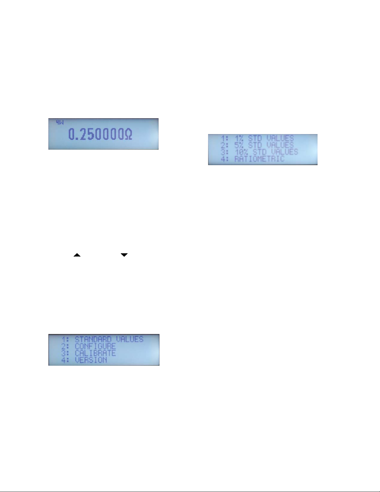
The main display shows the resistance
value in ohms or temperature value if tables
are used. The main display also shows if the
unit is confi gured for 4W (4-wire mode) or 2W
(2-wire mode) in the upper left corner of the
display.
Figure 3-1 Main Display showing 4-Wire
See section 3.2.3 for more information on
2-wire and 4-wire connections.
3.4.2 Setting a Resistance Value
To set a resistance value use the numeric
keypad to enter the value followed by the
ENTER button. The 000 button can be used
to increase the resistance value by a factor of
1000.
The UP and DOWN keys can also
be used to increment or decrement the resistance value. See 3.4.6 INCR Key for more
information.
3.4.3 Menu Button
Pressing the MENU button will show four
selections. See Figure 3-2
3.4.4 Standard Values Screen
There are 4 selections available in the
STANDARD VALUES menu. The operation
of the standard values allows the PRS-300 to
be used as an automated resistance carousel
with built-in EIA “preferred value” resistance
tables of 1% (E96), 5% (E24), 10% (E12)
increments or RATIOMETRIC user specifi ed
increment.
Figure 3-3 Standard Values Menu
Press the numerical value 1 to 4 on the
keypad for the desired standard values.
Resistors are available in a number of
standard ranges, often called ‘preferred values’ These ranges, or series, are set out by the
Electronic Industries Association (EIA), and
common values are E12, E24, E48, and E96.
The number after the ‘E’ denotes the number of
values the series contains per decade.
The series are logarithmic and are derived
from the resistor tolerance; resistors with a
tighter tolerance can have more values in the
series that won’t overlap one another. The series are sometimes referred to by the tolerance,
the two being related as follows:
Figure 3-2 Menu Screen
Press the numerical value 1 to 4 on the
keypad for the desired selection.
Press the MENU button to cancel and
return to previous screen at anytime.
OPERATION
E12: 10% tolerance
E24: 5% tolerance
E48: 2% tolerance
E96: 1% tolerance
When a STANDARD VALUE is selected
on the PRS-300 pressing the UP or DOWN arrows will increment the resistance value to the
9
Page 20
PRS-300 Series
next “preferred” resistance value.
RATIOMETRIC allows a custom tolerance value to be entered by the user. The
default value is 0.8% but can be set to the
required value in %.
3.4.5 Tables Key
Pressing the TABLE key allows use of
tables. There are 9 tables that can be selected.
The fi rst 4 tables, 1 to 4, are defi ned as PT-100
C, PT-100 F, PT-1000 C and PT-1000 F where
C is degrees Celcius and F is degrees Fahrenheit.
Press TABLE key and then a number key
0 through 9 followed by the ENTER key will
select a table. Table 0 is defi ned as no table is
used and resistance is shown.
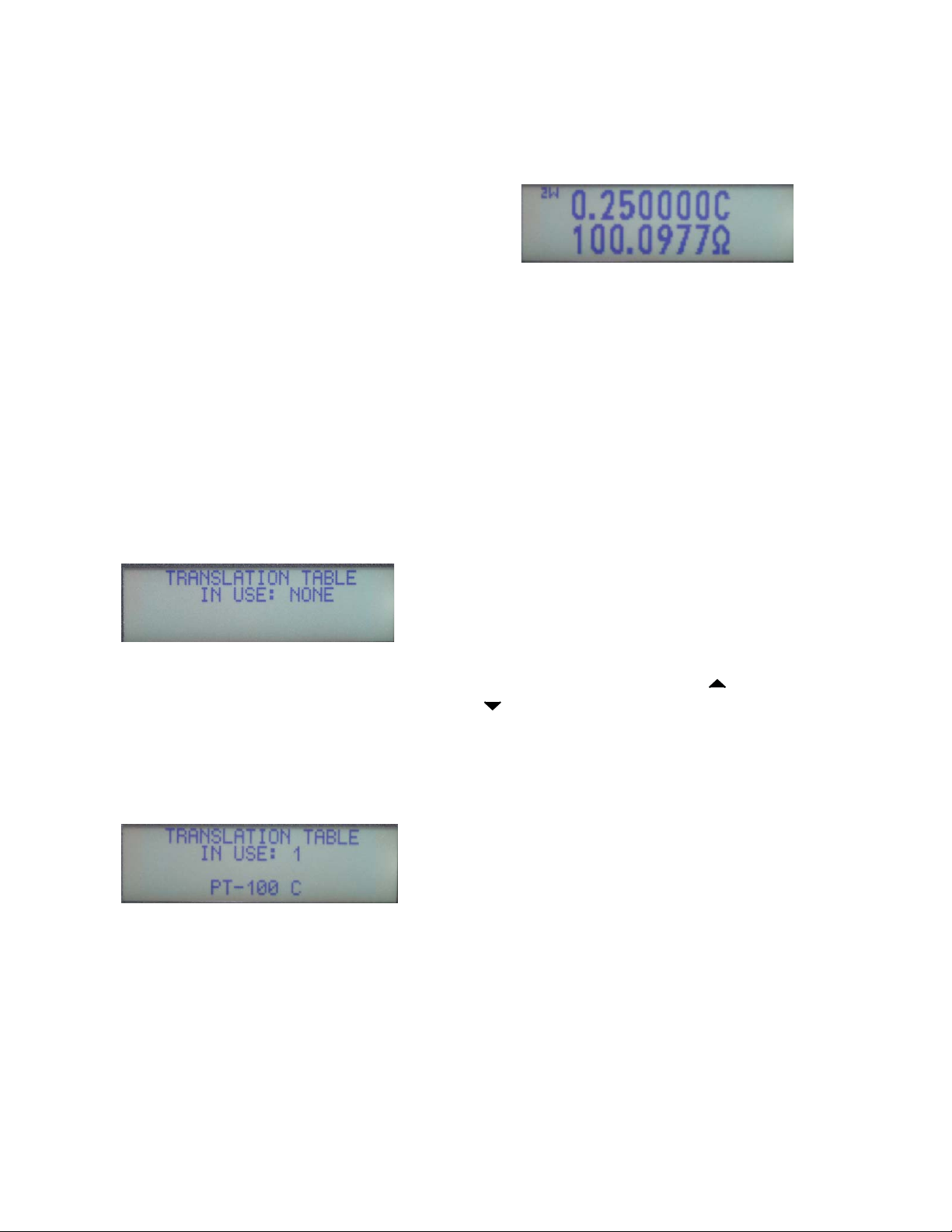
look like Figure 3-5 showing temperature on
top line and resistance on the bottom line.
Figure 3-5 PR-100 C set to 0.25 °C
For negative temperatures press the 000/
(-) key prior to entering the value.
If a value is not listed in the table and is
entered using the numeric keypad or selected
using the UP and DOWN keys interpolation is
used between the two closest table values.
Custom tables can be entered in locations
5 to 9 by using the USB interface and remote
CONIG:TABLE commands. See Appendix B
for more information.
Figure 3-4 No translation Table
Press the numerical value 1 to 9 on the
keypad for the desired table to be used. For
example pressing TABLE key, then “1” and
ENTER key will select use of the PT-100 C
table as shown in Figure 3-5
Figure 3-5 Table 1 PT-100 C
Once the table is selected the display
will change showing temperature on top and
resistance on bottom. Any value entered via
front panel or remotely will be assumed to be a
table value rather than a resistance value. For
example if 0.25 is entered then the screen will
3.4.6 Increment INCR Key
The INCR key allows entry of a numeric
value. The numeric value representing the
step or increment size the UP and DOWN
keys use.
For example pressing INCR key and then
10 would result in the displayed value being incremented or decremented 10 for each time
the UP or DOWN key is pressed.
INCR can also be used for tables in the
same way so that the operator can press the UP
or DOWN key and increment or decrement the
displayed value in °C or °F.
3.4.7 OPEN Key
The OPEN key opens all relays in the
PRS-300 resulting in high resistance at the
resistance terminals. The display will shown
OPEN Ω. Pressing the OPEN key again will
cause the resistance to return to the previous
set value.
For short enter lowest value of 0.1 using keypad or remote.
10
OPERATION
Page 21
PRS-300 Series
3.4.8 STO, RCL Keys
The STO and RCL key are used to store
user defi ned values into memory. Press STO
key followed by 0 to 9 in the numeric keypad
stores the currently shown resistance value into
that memory location.
Press RCL key followed by 0 to 9 in the
numeric keypad recalls the resistance value
saved into memory to the currently displayed
value.
3.4.9 VOLT Key
The VOLT key should normally be set
to 0.5 V which allows us of the full resistance
range of the PRS-300. Pressing the VOLT key
followed by a numeric value representing the
maximum voltage being used in the applicaton will limit the lowest resistance that can be
entered to prevent damage to the PRS-300.
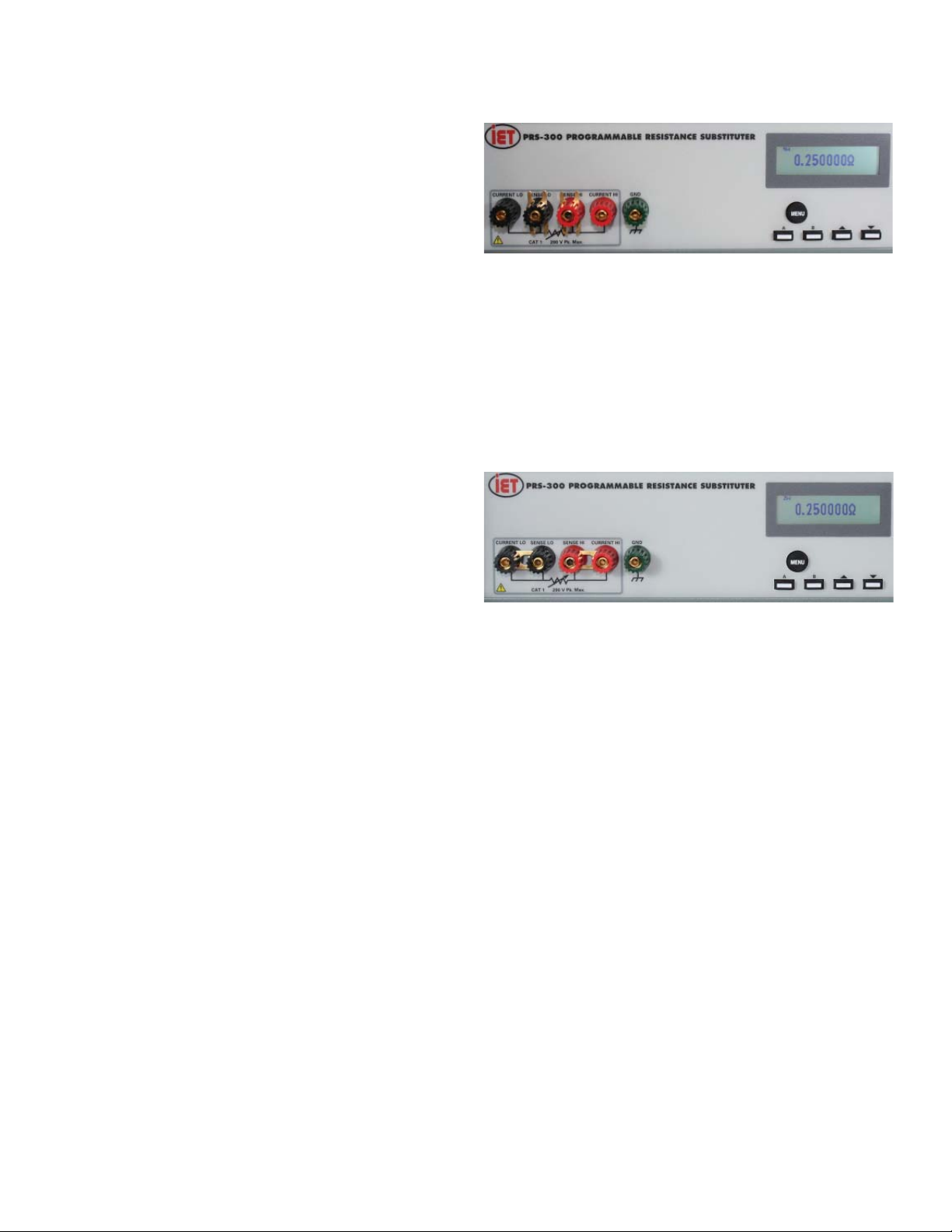
Figure 3-6 4-Terminal shorting links not connected
2W mode should be used when connecting to a 2 wire device or if the PRS-300 will be
used as a standard 2-terminal resistor such as
RTD simulation. In 2-wire mode shorting links
must be installed across high and low terminal
pairs.
The limited is based upon a maximum of
1 W being applied to the resistors. Note that
0.5 W is the maximum recommended and operation at 1 W can cause the internal resistors
to drift beyond specifi cation.
3.4.10 2 and 4 Wire Kelvin Lead Con-
nections
2-wire or 4-wire operation can be selected
from by pressing the MENU button, selecting
CONFIGURE, pressing the “2” will change
between 2-wire and 4-wire modes.
The use of 4W mode with Kelvin leads
minimize the effects of contact resistance and
gives best performance. In 4-wire remove the
shorting links from the high and low terminal
pairs.
Figure 3-7 Two terminal with shorting links
3.4.11 Thermal emf Considerations
The PRS Series uses high-quality, lowemf components. Thermal emf is primarily
attributable to the temperature difference
between the leads of the relay and the contacts
when temperature is applied to the coil. This
emf is of the order of 5 V per relay, but is not
usually additive. The typical worst case is <15
μV.
If the effect of tens of microvolts is
signifi cant to your application, connect to the
instrument with low-thermal-emf materials
only. Copper wire and copper alloys are recommended; brass and steel should be avoided.
Tinned copper and solder are acceptable.
OPERATION
11
Page 22

This emf will not be refl ected if an ac
measurement instrument is employed, and
can be eliminated by using a meter with “True
Ohm” capability. In other cases, the emf may
represent a very small component of a dc resistance measurement.
3.5 Environmental Conditions
The PRS is built, calibrated and intended
for use in a laboratory environment with a
nominal ambient temperature near 23oC. The
accuracy of the unit may be affected when
operated in non-laboratory environments. Always allow the instrument to stabilize at room
temperature after unpacking or relocating the
instrument. Humidity should be maintained at
laboratory conditions.
PRS-300 Series
3.6 Remote Operation
When the PRS is in REMOTE with front
panel locked out an REM indication will be
shown in the top right of the display.
12
OPERATION
Page 23
PRS-300 Series
4.1 Introduction
Chapter 4
USB INTERFACE
The standard USB connection is via a
standard USB B female connector located on
the rear panel. This can be connected to a
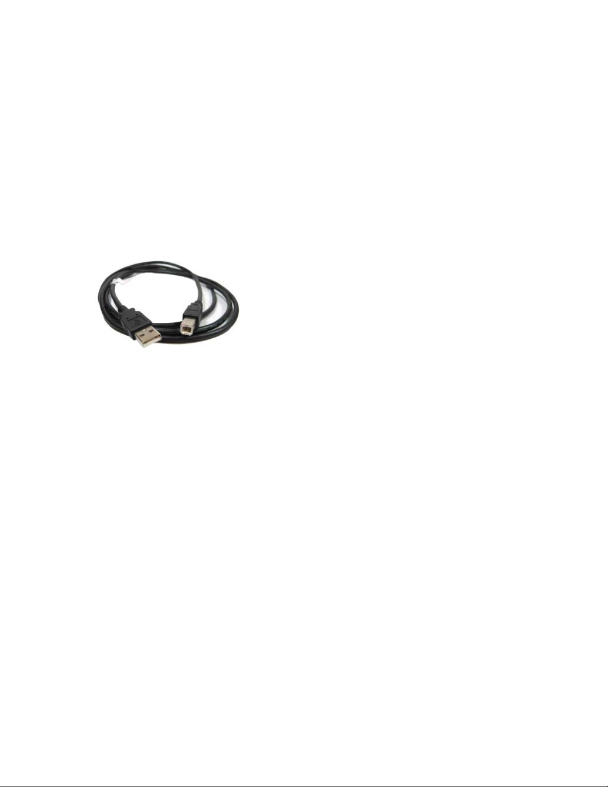
PC via a standard USB 2.0 A Male to B Male
Cable.
Figure 4-1 USB 2.0 A Male to B Male
Cable
The SCPI standard provides a tree like
series of standard commands for programmable instruments so that similar instruments
by different manufacturers can be controlled by
the same program.
4.3.1 Standard USB Interface
The standard USB interface uses a standard FTDI chip set. Drivers can be found from
ftdi or the link below.
http://www.ietlabs.com/prs-300-programmable-decade-resistor.html
Data Rates and Formats
Baud Rate: 9600 baud
Date bits 8
Parity none
Stop bits 1
4.3.2 Optional IEEE Interface with
High Speed USB Interface
The USB interface that comes with the
optional ieee interface uses an MCP2200 chip
set. This is a higher speed USB interface than
the standard USB interface.
Drivers can be found at the link below.
http://www.ietlabs.com/prs-300-ieeeethernet.html
4.2 Capabilities
The USB interface provides remote con-
trol over all functions except POWER.
4.3 USB Operation
The USB uses the command set outlined
in Appendix B. Data should be terminated
with LF line feed.
Normally when the PRS-300 is connected
to a computer using the USB port, Windows
7 and higher will search for the correct driver
and as long as the computer is connected to
the internet the driver should automatically be
installed.
USB INTERFACE
Data Rates and Formats
Baud Rate: 9600 baud
Date bits 8
Parity none
Stop bits 1
13
Page 24

PRS-300 Series
IEEE INTERFACE OPTION14
Page 25

Chapter 5
ETHERNET INTERFACE OPTION
5.1 Ethernet Programming
PRS units, with Ethernet interface option, come with Ethernet remote programming
capability accessed through the RJ45 LAN
connector. The connector is a RJ45 industrystandard connector found on the rear panel.
The PRS’s Ethernet connection is based upon
the ICS Ethernet/GPIB/USB to Serial Interface
Card. More information can be found at www.
icselect.com on the 9006 Ethernet/GPIB/USB
to Serial Interface Card.
Ethernet Protocols
The PRS supports Raw Socket and the
VXI-11 protocol which makes it easy to control from a PC or over the company network.
Raw socket lets you telnet to it and is best
used with direct PC to instrument applications.
VXI-11 operates over Sun RPC and is a more
secure protocol that mimics GPIB control of an
instrument and provides secure communication
over a company network or over the Internet.
Raw Socket Operation
The PRS is always ready for a telnet connection. When connected, the PRS outputs
its IDN message to confirm the connection.
All raw socket messages are terminated
with a linefeed. Carriage returns and ignored. A
backspace character causes the prior character to
be deleted. Communication timeout is two minutes and it is recommended that the client issue a
Space-BS sequence on an occasional basis, less
than the timeout, to reset the timeout counter.
PRS-300 Series
VXI-11 Background
VXI-11 is a communication standard developed in conjunction with the VISA Specifi cation.
The specifi cation defi nes a VXI-11.3 interface
like the PRS as an instrument which can be
controlled in Windows systems by programs
that make VISA or SICL library calls and in
UNIX/LINUX or similar operating system with
RPC calls. The VXI-11 specifi cation provides
an RPCL (Remote Procedure Call Library) that
can be used by virtually any operating system to
control the PRS. Microsoft’s RPC is not ONC
compliant and cannot be used with a VXI-11.3
device like the PRS. An VXI-11.3 interface
like the PRS will operate in an LXl system and
it supports LXI’s ‘VXI Discovery Method’.
5.2 Network Setup
The PRS includes an internal WebServer with
HTML web pages that can be accessed by a web
browser from any computer. The web pages let
the user quickly change the PRS network settings.
The default IP address is 192.168.1.253 static.
5.3 Ethernet Test Keyboard
To assist the user in setup and communication the VXI-11kybd program
can be used which includes defined RPC
calls to change the PRS network settings.
VXI-11 Keyboard Control Program provides
interactive control of VXI-11 instruments from
the computer keyboard without having to write a
program. The VXI-11 Keyboard program is the
ETHERNET INTERFACE OPTION
15
Page 26

PRS-300 Series
ideal utility program for confi guring and testing the
PRS or any VXI-11 compatible instrument. Use
the VXI-11kybd program to exercise the interface
or to try out commands before using them in a
program. The VXI-11kybd program can be found
on the PRS product page at www.ietlabs.com
Versatile Programming
The PRS can be easily controlled by several
programming techniques and languages because
it is a VXI-11.3 instrument. If you program
with LabVIEW, National Instruments’ VISA
supports VXI-11.3 instruments like the PRS. NI’s
Measurement and Automation Explorer treats
the PRS as a TCP/IP compliant device. Agilent’s
VISA library supports VXI-11.3 instruments and
the Agilent Connection Manager sees the PRS as
a TCP/IP instrument.
If you are a Visual Basic, VB.Net or C/C++
programmer, you can write your program to
call Agilent’s or National Instruments’ VISA
or Agilent’s SICL library in the Windows
environment.
If you use LINUX or any other fl avor of UNIX
like SunOS, IBM-AIX, HP-UX, or Apple’s OS X,
you can communicate with the PRS through RPC
over TCP/IP. RPC (or Remote Procedure Calls)
provides an invisible communication medium for
the developer. The VXI-11 specifi cation provides
an RPCL (Remote Procedure Call Library) that
can be used by virtually any operating system
to control the PRS.
If you program with Java then you can write a
PRS control program that can be easily moved
to many different operating systems.
The Java jGpibEnet project on SourceForge was
developed using an ICS 8065 Controller similar
to the PRS Controller.
commands as outlined in Appendix A.
When shipped, the boards are confi gured with
default settings outlined in Table 4-1 Default
Settings.
Command Function Factory Setting
IP Mode Static or DHCP
Mode
IP Address 0.0.0.0 to
255.255.255.255.0
Net Mask 0.0.0.0 to
255.255.255.255.0
COMM Timeout Sets socket timeout 120 sec.
Auto Disconnect Aborts socket if link
count goes to 0
Static
192.168.1.254
255.255.255.0
Off
Table 4-1 Default Settings
Review the Table with your network administrator
and decide on which settings, if any, that need
to be changed. Table 4-1 provides detailed
information about each network setting to help
you with your decisions. The minimum change
is to set a static IP address so your PC can
communicate with the board.
The network confi guration can be changed and
the board’s MAC Address can be read with a web
browser, by running ICS’s VXI-11 Confi guration
Utility on a WIN32 or WIN98 PC. ,
5.5 Web Browser Configuration
Method
This method uses a standard browser such as
Firefox, Internet Explorer or Safari to view and
change the current network settings.
1. Temporarily disconnect the computer from
the company network. Connect the PRS and
computer running the browser using a standard
Ethernet Cables to a hub or switch. Temporarily
disconnect the local network connection to avoid
network confl icts until the board is confi gured.
5.4 Network Confi guration
This paragraph confi gures the 9006 card in the
PRS for operation on your network. The board’s
digital interface is confi gured later by sending
16
ETHERNET INTERFACE OPTION
Page 27
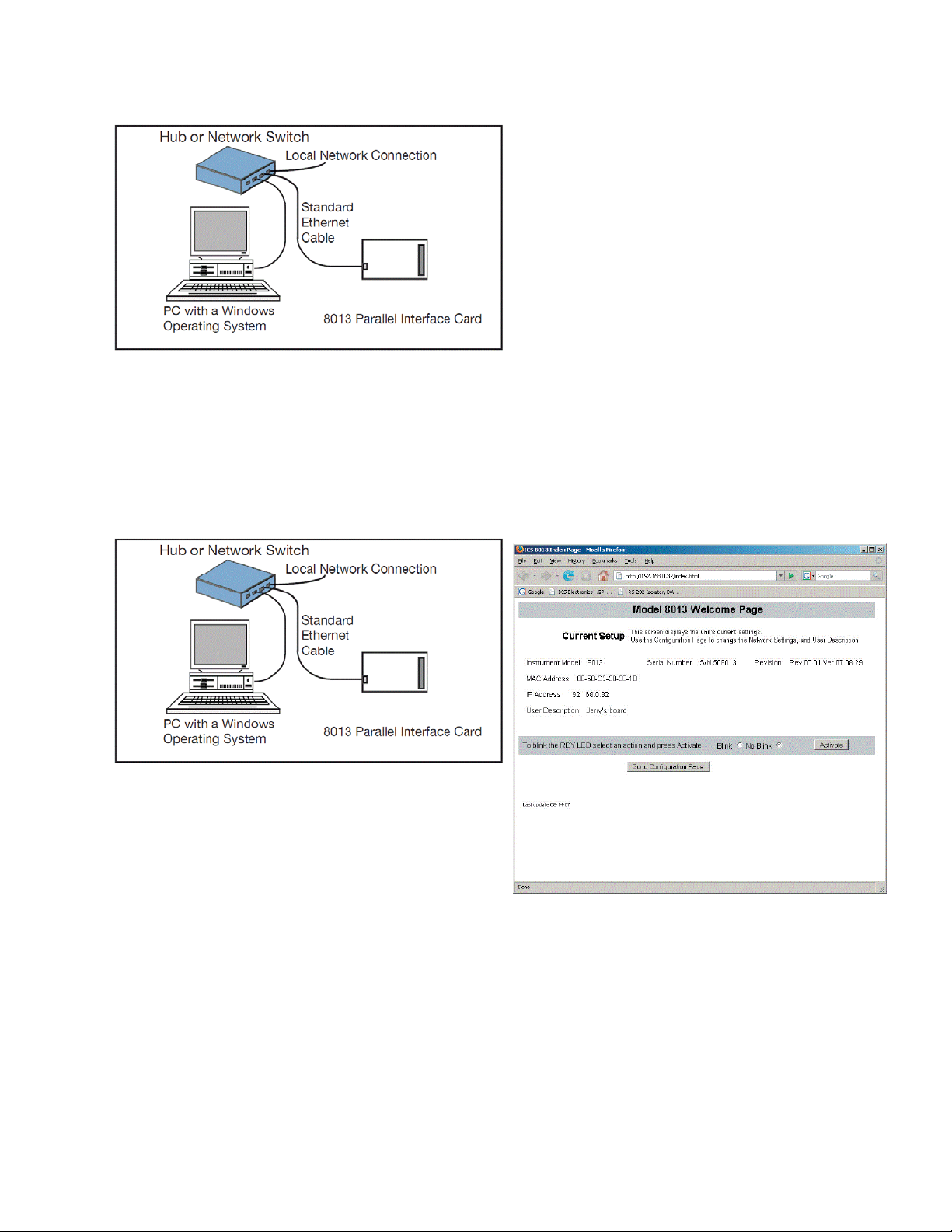
Figure 4-1 9006 Connected to the local hub
gpp
y
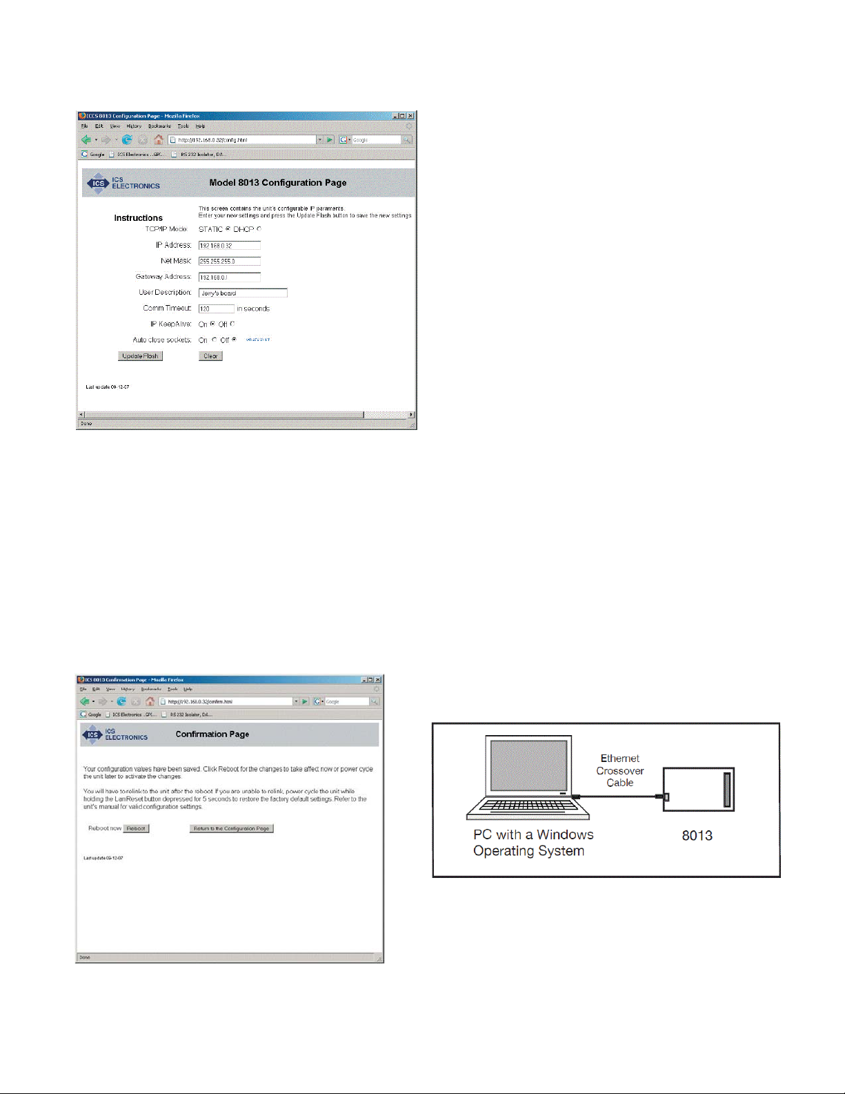
An alternate connection is to use an Ethernet
Crossover Cable to connect the computer directly
to the PRS for initial confi guration. This will
eliminate any potential network confl icts while
confi guring the PRS.
PRS-300 Series
a different range, record the current settings and
temporarily set the following network values:
Check ‘Use the following IP Address’
IP Address 192.168.1.254
Subnet mask 255.255.255.0
4. Open the browser and enter the default IP
address of 192.168.1.254 for new units (or your
last set address for older units) in the browser
address window.
5. A Welcome Page similar to the one shown
Figure 4-3 should appear in your browser.
6. If you want to change any of the settings,
press the ‘Update Configuration’ button. A
Confi guration Page similar to the one shown in
Figure 4-4 should appear in your browser.
Figure 4-2 9006 Connected to the local hub
2. Apply power to the PRS. Set the Remote local
switch to Remote.
3. Check your computer’s network settings to
be sure its IP address is in the 192.168.1.xxx
Figure 4-3 9006 Welcome Page
range so it can communicate with the PRS
Ethernet board’s default IP address. If it is not,
it must be set before proceeding. Use the values
shown below. For Windows PCs, right-click on
My Network Places and click on Properties.
Right-click on Local Area Connection and click
Properties. Highlight Internet Protocol (TCP/IP)
and click Properties. If your PC’s IP address is in
ETHERNET INTERFACE OPTION
17
Page 28
PRS-300 Series
gg
8. Your new settings have been saved in the
board’s fl ash memory. You have to reboot the unit
or power cycle it for the changes to take affect.
Press the ‘Reboot’ button to reboot the unit now
or the ‘Return to the Confi guration Page’ button
to revisit the new settings.
5.6 VXI-11 Configuration Utility
Method
The VXI-11 Configuration Utility program
is called ‘VXI11_confi g.exe’ and runs in any
WIN32 PC with Windows 98, Me, 2K, XP,
Vista, 7 and Server 2003 operating systems. The
VXI11_confi g.exe program can be found on the
PRS product page at www.ietlabs.com.
Figure 4-4 9006 Confi guration Page
7. Enter the new settings as desired. If you select
DHCP for the TCP/IP Mode, the page blanks out
the IP, Net and Gateway addresses as they will
be supplied by your DHCP server. Check the
entered values carefully as the unit’s webserver
does minimal error checking. Press the ‘Update
Flash’ button when done. A Confi rmation Page
similar to the one shown in Figure 4-5 will appear
in your browser.
The VXI11_confi g program can be run from the
CD or can be installed onto your hard disk and
run from the installation directory.
VXI11_confi g.exe is a Visual Basic program and
requires that either Microsoft’s Visual Studio 6
or VBruntime6 be installed on your PC to run.
1. Connect the board directly to the WIN32 PC
that will be running the Confi guration Utility.
Disconnect the PC from the company network
and use the supplied Ethernet Crossover Cable to
connect the PC to the board as shown in Figure
4-6. This will eliminate any potential network
confl icts while confi guring the board.
Figure 4-5 9006 Confi rmation Page
18
Figure 4-6 9006 Connected to PC with a
Crossover Cable
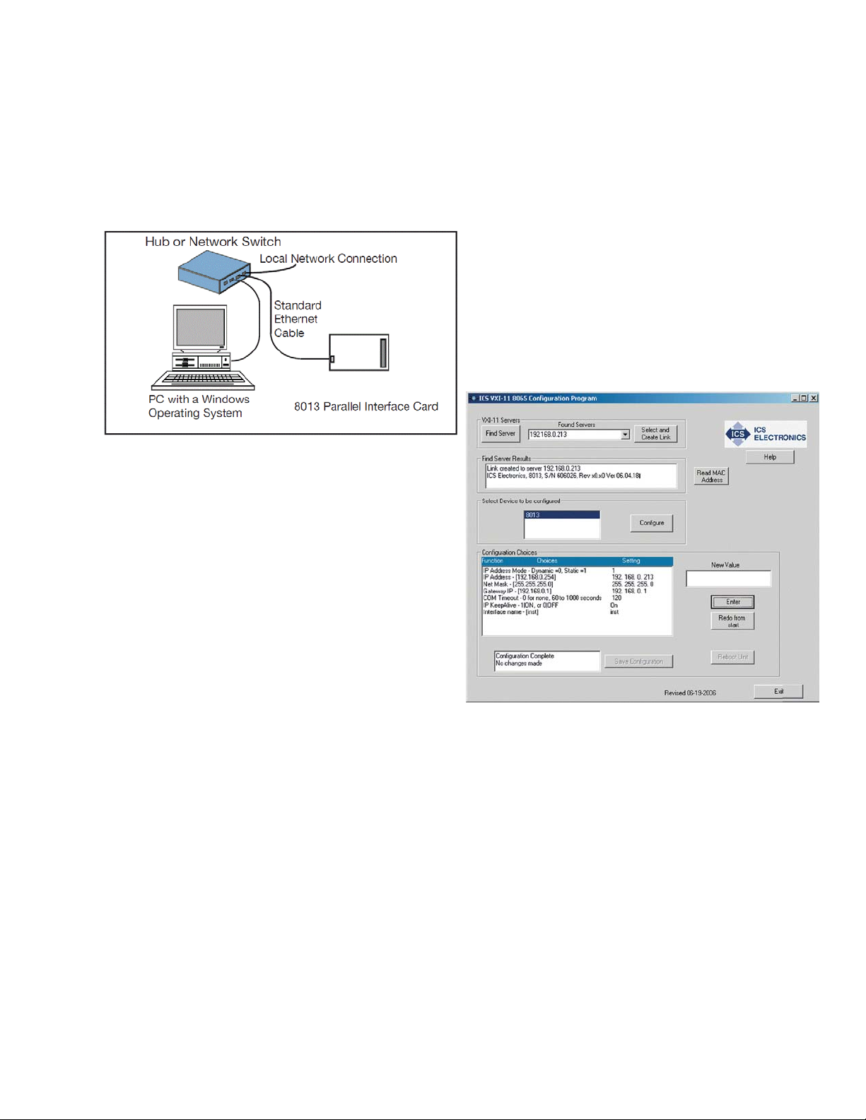
Alternately, use a standard Ethernet patch cable
ETHERNET INTERFACE OPTION
Page 29
PRS-300 Series
to connect the 9006 to the same hub or switch
that the PC running the Confi guration Utility is
connected to as shown in Figure 4-7. Temporarily
disconnect the local network connection to avoid
network confl icts until the board is confi gured.
Figure 4-7 9006 Connected to the local hub
2. Apply power to the board
scans for all VXI-11 Services connected to the
local LAN or to your PC. (The 9006 is an RPC
server which provide a VXI-11 Service) The
results are displayed in the Results box.
6. When the servers(s) have been found, use the
pulldown arrow in the Found Servers box to view
the Found Server addresses. The board’s
default address is 192.168.1.254. Highlight the
board’s IP address and click the Create Link
button. If the server is not found, you can enter
the default IP address (192.168.1.254) in the
Found Servers box. Click the Create Link button.
3. Check your PC’s network settings to be sure
its IP address is in the 192.168.1.xxx range so
it can communicate with the board’s default IP
address. To check, right-click on My Network
Places and click on Properties. Right-click on
Local Area Connection and click Properties.
Highlight Internet Protocol (TCP/IP) and click
Properties. If your PC’s IP address is in a different
range, record the current settings and temporarily
set the following network values:
Check ‘Use the following IP Address’
IP Address 192.168.1.254
Subnet mask 255.255.255.0
4. Run the VXI11_config program. The
Confi guration Utility opens a window as shown
in Figure 4-8. Initially only the Find Server, Help
and Exit buttons are enabled on the program
window. The other buttons will be enabled as
you advance through the program.
5. Click on the Find Server button. The program
Figure 4-8 VXI-11 Confi guration Utility
(Showing all configuration choices with no
changes)
7. When the link has been created, device model
number(s) will appear in the ‘Select Device to
be Confi gured’ box. Highlight the desired model
number and click the Confi gure button to start the
confi guration process.
8. The Confi guration Choices box displays only
one line with the fi rst parameter to be changed
and its current setting. If you like the current
setting, click Enter to advance to the next
ETHERNET INTERFACE OPTION
19
Page 30

PRS-300 Series
parameter. If you want to change the setting,
type a new value in the New Value box and click
Enter. The program will send your setting to the
board and read back the new setting. Repeat as
needed to make another change or click Enter
again to advance to the next parameter.
9. Repeat step 8 for each confi guration parameter.
Figure 4-8 shows the VXI-11 Configuration
Utility after all parameters have been entered
for a Model 9006. Click the Redo From Start
button if you need to start over or if you want to
change any of the prior settings
10. When done, the Save Confi guration button
is enabled if you changed any settings. Click the
Save Confi guration button to save the values
in the board’s fl ash memory. If you did not make
any changes you can just exit the program.
11. The board has to be power cycled or rebooted
before the confi guration changes take affect.
Click the Reboot button to reboot the board and
use the new settings.
The Digital I/O confi guration values are not
affected by the LAN Reset operation.
Command Function Factory Setting
IP Mode Static or DHCP
Mode
IP Address 0.0.0.0 to
255.255.255.255.0
Net Mask 0.0.0.0 to
255.255.255.255.0
COMM Timeout Sets socket timeout 120 sec.
Auto Disconnect Aborts socket if link
count goes to 0
Static
192.168.0.2
255.255.255.0
Off
Table 4-2 Default Settings
5.8 PRS Programming
A PRS SCPI command reference is included in Appendix A. This gives a complete
set of commands.
An example of commands to be sent to
place the PRS in remote, this must be done
fi rst otherwise the will be no remote control of
output impedance, and then confi gure the unit
for a specifi c impedance value.
12. Press the Exit button to quit the VXI11_confi
g program.
13. If the IP address was changed to an address
outside the 192.168.1.xxx range in step 3, your
PC’s network settings will have to be changed to
communicate with the board. Exit the VXI11_
confi g program and restore the PC’s network
settings.
5.7 Resetting Default Network
Settings
The board can be reset to the default network
settings listed in Table 4-2 at any time by holding
the LAN Reset Button in for 5 seconds while
applying power to the board. Access to this button
is on the rear panel of the PRS-300..
Where the command string is constructed
as described in Appendix A and Appendix B.
A command string might be, for example:
SOURce:DATA 1000000.1
20
ETHERNET INTERFACE OPTION
Page 31

PRS-300 Series
Chapter 6
IEEE INTERFACE OPTION
6.1 Introduction
The IEEE interface option makes the
PRS-300 a IEEE-488.2-1987 and SCPI 1994.0
compatible instrument. The PRS-300 IEEE488 interface is based upon the ICS Ethernet/
GPIB/USB to Serial Interface Card. More
information can be found at www.icselect.
com on the 9006 Ethernet/GPIB/USB to Serial
Interface Card.
The IEEE STD 488.2 covers the electrical
and mechanical bus specifi cations, and state
diagrams for each GPIB bus function. It also
establishes data formats, common commands
for each 488.2 device and controller protocols.
The standard is available on-line at http://www.
ieee.org.
The SCPI standard provides a tree like
series of standard commands for programmable instruments so that similar instruments
by different manufacturers can be controlled
by the same program. SCPI information and a
command reference are located in Appendix A.
6.2 Capabilities
The IEEE option provides remote control
over all functions except POWER. The IEEE
option responds to all Basic Commands in Appendix B and all IEEE.2 Mandated common
commands in Appendix A.
6.3 Address Switch and
Communications Settings
The default GPIB address is 4. This address can be changed remotely by sending the
command SYSTem:ADDR <n> where n is 0
- 30.
6.4 GPIB Test Keyboard
To aid the user in operating the PRS, a
GPIB “Keyboard” Controller program - the
easiest way to control GPIB devices without
writing a program - is available from IET. This
GPIB Keyboard program automatically fi nds
your device at start-up and it lets you enter just
the data that you want to send to the device.
This program works with ICS, Measurement
Computing and National Instruments controllers.
Other tutorials are available on-line; consult IET for additional information. A software
GPIB “keyboard” can be found at www.ietlabs.
com
IEEE INTERFACE OPTION
To implement, request a download of
ICS_GPIBkybd_Install.zip from IET Labs
Tech Support.
21
Page 32

Unzip the fi le and follow instructions to
install.
Open the application. You may use the
Find Listeners button to confi rm that the PRS
unit is recognized. Other instruments may also
be recognized at this time.
PRS-300 Series
IEEE INTERFACE OPTION22
Page 33

PRS-300 Series
PROGRAMMING
7.1 Program Commands
7.1.1 Calibration Interval
The standard USB interface can be programmed via any of the commands listed in
Appendix B.
Chapter 7
For USB and RS-232 interfaces, <lf>,
<cr> or <crlf>, can be used as terminator. The
device returns in this case <crlf>. The device
performs all commands previously sent after it
receives a terminator.
The optional Ethernet/IEEE/USB card can
be programmed via any of the commands listed
in Appendix A and Appendix B.
PROGRAMMING
23
Page 34

PRS-300 Series
24
PROGRAMMING
Page 35

Chapter 8
MAINTENANCE
8.1 Verifi cation of Performance
8.1.1 Calibration Interval
The PRS Series instruments should be
verifi ed for performance at a calibration in-
terval of twelve (12) months. This procedure
may be carried out by the user, if a calibration
capability is available, by IET Labs, or by a
certifi ed calibration laboratory. If the user
should choose to perform this procedure, then
the considerations below should be observed.
8.1.2 General Considerations
It is important, whenever testing the PRS
Series Decade units, to be very aware of the capabilities and limitations of the test instruments
used. Such instruments have to be signifi cantly
more accurate than the specifi ed accuracy for
all applicable ranges in order to perform this
task, allowing for a band of uncertainty of the
instrument itself, the test setup and the environment; consult IET Labs for information.
It is important to allow both the testing
instrument and the PRS-300 to stabilize for
a number of hours at the nominal operating
temperature of 230C, and at nominal laboratory conditions of humidity. There should be
no temperature gradients across the unit under
test.
In the case of the PRS-300 a Kelvin type
4-wire test terminals should be used to obtain
accurate low-resistance readings.
PRS-300 Series
Steps should be taken to minimize
thermal-emf effects, by maintaining an even
temperature and by using only low-emf connectors. Use of meters with a “True Ohm”
function is recommended.
Proper metrology practices should be followed in performing this verifi cation.
8.1.3 Calibration Procedure
1. A DMM is used to measure the resistance
of the PRS-300. The DMM should have a
measurement accuracy signifi cantly more
accurate than the ±(70 ppm + 1 m) for all
resistance values.
2. Determine the allowable upper and lower
limits for each resistance setting as would
be done for a decade box from 0.1 to 20
Ms based on the specifi ed accuracy of the
PRS-300.
3. Confi rm that the resistances fall within these
limits
4. If any resistances fall outside these limits, See
section 8.1.3 Adjustment of internal resistors.
8.1.4 Adjustment of Internal Resistors
During the adjustment process a DMM
such as the Fluke 8508A or Keysight 3458A
using 7 ½ digits of resolution or better is connected to the binding posts of the PRS-300
using a 4 terminal Kelvin connection.
The gold shorting links must be removed
on the binding posts of the PRS-300.
MAINTENANCE
25
Page 36
PRS-300 Series
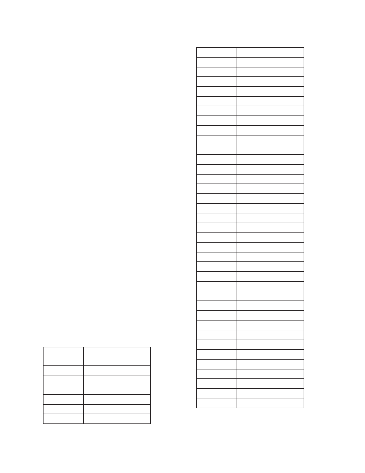
The PRS-300 consists 43 internal resistors
which are combined in either series or parallel to achieve the programmed resistance. The
gold shorting links must be removed on the
binding posts of the PRS-300.
These resistors require periodic measurement to keep the PRS-300 within published
specifi cations. The resistors are measured
using a DMM. The measured value is then
stored in a table within the memory of the
PRS-300. The measured values of the resistors
are used in an algorithm to determine which
resistors are used to create the programmed
resistance value.
In addition to the 43 resistors the residual
internal lead resistance is also measured at time
of manufacture and entered into memory. The
internal lead resistance does not need to be
measured again unless repair has been performed to the PRS-300.
Below is a list of the 43 resistors and
their nominal resistance value. These resistors
should be within ±1% of the nominal value for
R1 to R5 and ±0.1% of the nominal value for
R6 and higher to ensure proper operation of the
PRS-300. If the measured value of the resistor is outside of these specifi cations service is
required.
Resistance
Number
Nominal Resistance
Value
R1 0.17
R2 0.35
R3 0.7
R4 1.37
R5 2.66
R6 5.15
R7 10.2
R8 20.0
R9 38.8
R10 75.6
R11 148.0
R12 287.0
R13 570.0
R14 1.13 k
R15 2.23 k
R16 4.4 k
R17 8.7 k
R18 17.0 k
R19 33.3 k
R20 66.0 k
R21 130.0 k
R22 258.0 k
R23 506.0 k
R24 1.0 M
R25 2.0 M
R26 3.99 M
R27 7.8 M
R28 15.0 M
R29 30.0 M
R30 60.0 M
R31 120.0 M
R32 3.55 k
R33 7.39 k
R34 16.4 k
R35 33.8 k
R36 72.2 k
R37 147.0 k
R38 300.0 k
R39 600.0 k
R40 1.23 M
R41 2.48 M
R42 5.0 M
R43 10.0 M
26
MAINTENANCE
Page 37

During the adjustment process the
fi rmware cycles through each resistor and the
technician can enter the measured resistance
value in ohms. This should be done with a
minimum of 7 ½ digits of resolution. The
accuracy of measurement should be signifi -
cantly more accurate than the ±(70 ppm + 1
m) for all resistance values.
To enter into the calibration process,
press the MENU key and then select 3 for
calibration. At the end of the process all calibration values will be saved into memory.
At anytime pressing the MENU key will
exit calibration without making any changes.
IET Labs uses the Fluke 8508A, set to 7
½ digits of resolution, during the adjustment
process to ensure the PRS-300 meets specifi -
cations.
PRS-300 Series
IET Labs offers the PRS-DMM software
which works with the PRS-300 and Fluke
8508A or Keysight 3458A to automate this
adjustment process. See Chapter 9.
MAINTENANCE
27
Page 38

PRS-300 Series
Chapter 9
PRS-DMM Self Adjusting Software
9.1 PRS-DMM Self Adjusting
Software
9.1.1 Overview
The PRS-DMM Self Adjusting Software is
a Windows based software package using LabVIEW 2013 RTE.
The software is designed to be used with
the PRS-300 Programmable Resistance Substituter and the Keysight 3458A or Fluke 8508A
DMMs.
The DMM is used to measure the resistance
of the PRS-300, and then the software adjusts
the output resistance of the PRS-300 to achieve
the closest possible resistance value to the target
resistance value.
This can improve the accuracy of the PRS300 from ±(70 ppm + 1 m) to better than ±10
ppm short-term without switching.
9.1.2 General Requirements
The PRS-DMM Self Adjusting Software
does require:
• Windows 8 or Windows 10 PC
• National Instruments GPIB-USB-HS or
equivalent GPIB interface
• Fluke 8508A DMM or Keysight 3458A
DMM
• PRS-300 Programmable Resistance
Substituter
• Kelvin cables between PRS-300 and
Fluke 8508A
• GPIB cables as necessary
9.1.3 Software Installation
Install the PRS-DMM Self Adjusting
Software using the supplied USB stick. This
will install the PRS-DMM software as well as
the LabVIEW 2013 RTE. This software is also
available at http://www.ietlabs.com/prs-dmm.
html
If using the PRS-300 with standard USB
interface, the FTDI driver should also be installed. These can be downloard at http://www.
ietlabs.com/Drivers/FTDI.zip
9.1.4 Connection between DMM and
PRS-300
Connect the PRS-300 to the DMM using
good quality low thermal EMF cables using a 4
terminal kelvin connection.
If the end use of the PRS-300 will be 2
Wire then keep shorting links installed. In the
menu of the PRS-300 it should be confi gured for
“2W” Mode.
If the end use of the PRS-300 will be 4 wire
then remove shorting links. In the menu of the
PRS-300 it should be confi gured for “4W” mode.
See section 3.4.10 for more information on
2-wire and 4-wire connections.
9.1.5 Connections of PRS and DMM
Connect the 3458A or 8508A DMM to the
28
PRS-DMM SOFTWARE
Page 39
PRS-300 Series
PC via GPIB. Connect the PRS-300 to the PC
via GPIB or USB. Make sure the addresses are
different on DMM and PRS-300.
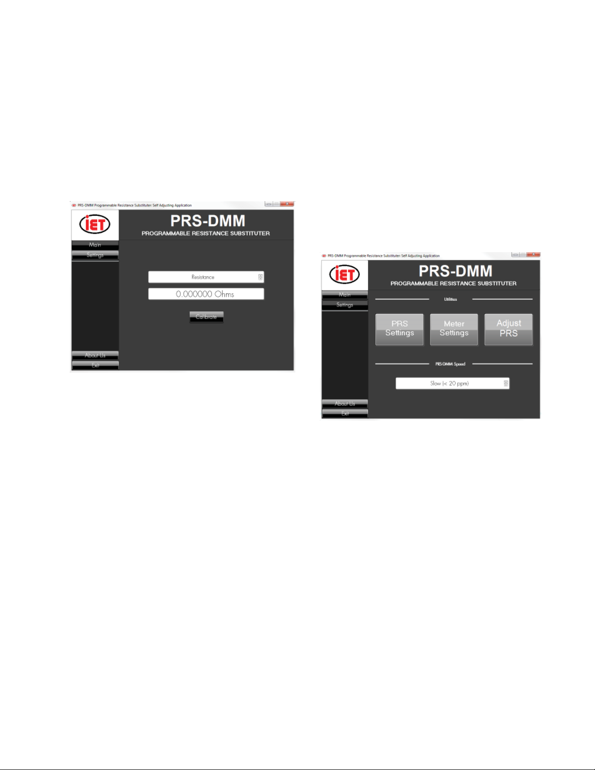
9.2 PRS-DMM Main Screen
The main screen of the PRS-DMM soft-
ware is shown below.
SPEED . See section 9.3.5.
9.3 PRS-DMM Settings
9.3.1 PRS-DMM Settings Screen
The Settings screen is shown in Figure
9.2. This menu should be confi gured fi rst to
set address of the PRS-300 and DMM.
This menu also allows for adjustment of
the PRS-300 which automates the adjustment
process of the PRS-300 as described in section
8.4.1.
Figure 9.1 PRS-DMM Main Screen
There are 4 buttons; Main, Settings, About Us
and Exit.
9.2.1 PRS-DMM Main Screen Opera-
tion
The main screen of the PRS-DMM allows
the user to select Resistance or RTD tables, and
it also allows to be entered the target resistance
value or temperature.
Assuming that the PRS-300 is connected
to the PC and turned on, any value entered as a
target value will automatically switch the PRS300 to that resistance or resistance equivalent
to the entered temperature value.
Clicking on the Calibrate button starts the
process of of adjusting. The DMM Measures
and adjusts the PRS-300 to achieve the closest
value possible to the entered target value. The
accuracy depends upon the MEASUREMENT
Figure 9.2 PRS-DMM Settings Screen
9.3.2 PRS Settings
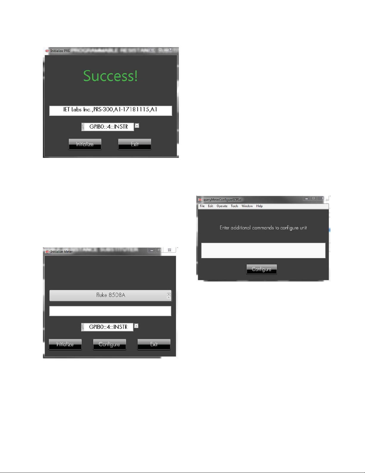
PRS Setting screen allows the operator
to select the COM port or GPIB address of the
PRS-300. Make sure the PRS-300 and DMM are
turned on and connected to the PC.
If the address or COM port of the PRS300 or DMM is not shown in the I/O box then
click on refresh. Select the GPIB address or
COM port and then click the Initialize button.
The IDN string will be shown in the white box
along with a Success indication.
Click Exit button to return to Setting
Screen once PRS has been detected.
PRS-DMM SOFTWARE
29
Page 40
PRS-300 Series
Figure 9.3 PRS Settings Screen
9.3.3 Meter Settings
Meter Setting screen allows the operator to
select which DMM will be used either the Fluke
8508A or the Keysight 3458A. The GPIB address of the DMM can also be set in this menu.
Make sure the DMM is turned on and connected
to the PC.
priate resolution 7 ½ digits for slow, 6 ½ digits
for medium and fast, 4 wire measurements and
autorange ON.
The 8508A will also be confi gured for
Low Current, Fast AD Integration OFF, and
Analog Filter OFF.
If additional commands need to be sent to
the DMM, click on the Confi gure Button and
enter the commands in the text box.
Once the commands have been entered
press the Confi gure button. Any commands
will be send to the DMM during initialization
of the DMM.
30
Figure 9.4 Meter Screen
Select the GPIB address and then click
the Initialize button. The IDN string will be
shown in the white box along with a Success
indication.
The PRS-DMM software will confi gure
the DMM for resistance measurements, appro-
Figure 9.5 Meter Confi gure Screen
Click Exit button to return to Setting
Screen once DMM has been detected.
9.3.4 Adjust PRS
Clicking on the Adjust PRS button will step
the operator through the PRS-300 adjustment
procedure. The procedure consists of measuring all 43 internal resistors using the DMM and
storing the actual resistance values into a table.
These resistance values are used in the algorithm
to create the programmed resistance value. See
section 8.1.4 for more information.
PRS-DMM SOFTWARE
Page 41

9.3.5 PRS-DMM Speed
There are three selections for PRS-DMM
Speed. These selection affect the accuracy from
the target value and time to make the measurements.
Slow measurements are made with 7 ½
digits of resolution, and measurements and adjustments are made until the accuracy is better
than ±20 ppm.
Medium measurements are made with 6
½ digits of resolution and measurements and
adjustments are made until the accuracy is better
than 40 ppm.
Fast measurements are made with 6 ½ digits
of resolution. There are no adjustments made
in fast mode. The value from the DMM is just
displayed.
PRS-300 Series
The uncertainty of the measurement is also
displayed. The uncertainty is based upon the
specifi cations given in the manual for the Fluke
8508A or Agilent 3458A. The uncertainty is
based upon either 6 ½ or 7 ½ digits of resolution,
absolute uncertainty for 365 days and a 95%
confi dence level.
PRS-DMM SOFTWARE
31
Page 42

PRS-300 Series
32
PRS-DMM SOFTWARE
Page 43

Appendix A
SCPI COMMAND REFERENCE
PRS-300 Series
SCPI is an acronym for “Standard Commands for Programmable Instruments”. For
additional information or an on-line copy of
this standard, see:
http://www.scpiconsortium.org.
The IEEE 488.2 Standard was established
in 1987 to standardize message protocols and
status reporting and to defi ne a set of common
commands for use on the IEEE 488 bus. IEEE
488.2 devices are supposed to receive messages in a more fl exible manner than they send.
A message sent from GPIB controller to GPIB
device is called: PROGRAM MESSAGE.
A message sent from device to controller is
called: RESPONSE MESSAGE. As part of the
protocol standardization the following rules
were generated:
(;) Semicolons separate messages.
(:) Colons separate command
words.
(,) Commas separate data fi elds.
<nl> Line feed and/or EOI as last
character
terminates a ‘program message’.
Line feed (ASCII 10) and EOI
terminates a RESPONSE MESSAGE.
(*) Asterisk defi nes a IEEE 488.2
common command.
(?) Ends a query where a reply is
expected.
SCPI builds on the programming syntax
of IEEE-488.2 to give the programmer the
capability of handling a wide variety of instrument functions in a common manner. This
gives all instruments a common “look and
feel”. SCPI commands are not case-sensitive.
The portion of commands shown in capitals denotes the abbreviated form of the keyword. Either the abbreviated or whole keyword
may be used when entering a complete command. There must be a space between the command and a parameter or channel list. Multiple
SCPI commands may be concatenated together
as a compound command by using semicolons
as command separators.
APPENDIX A 33
Page 44

PRS-300 Series
Keywords shown inside braces [ ] are
defaults, and are optional when constructing a
PROGRAM MESSAGE.
Terminators: For GPIB interface each
command line must end with line feed <lf>.
Response from the device also returns line feed
<lf>.
Commands not recognized have no effect
on the unit’s operation and will set the corresponding bits in the Standard Event Status
Register. SCPI commands that end with a question mark ‘?’ are queries. All queries should
be followed by reading their response to avoid
data loss.
Semicolon ‘;’ is used to separate more
commands written on one line.
IEEE-488.2 Common Commands
*IDN?
Returns instrument identifi cation “IET Labs,PRS-300,<Serial Number>,<software version>”
*ESR?
Returns the read of the event status register.
*STB?
Returns the read of the status byte register.
*ESE?
Returns the read of the event status enable register.
*SRE?
Returns the read of the service request enable register.
*ESE
Set the event status enable register value
*SRE
Set the service request enable register value
*RST
Reset the buffer
*TST?
Self test query
*CLS
Clear standard event status register
*OPC
Operation complete
*OPC?
Operation complete query
*WAIT
Wait until operation is complete before executing next command(No Function in PRS)
APPENDIX A34
Page 45

PRS-300 Series
*PCS
Power-on Status Clear
Note: Remote command can start with or without * symbol for compatibility.
2.13 Formats
IEEE 488.2 enables remote programming of all instrument functions, measurement conditions
and comparator settings etc. Outputs include measurement conditions, open/short corrections, and
measured values.
Data Formats
Data will be transmitted in ASCII NR3 format per IEEE488.2 sec. 8.7.4 and reproduced below.
Note that there is always precisely one digit before the decimal point, and precisely three digits in
the exponent.
Multiple results
For the case where a measurement produces multiple results (e.g. MEASure Cs, and DF), the
individual numbers will be separated by commas per IEEE488.2 para. 8.4.2.2.
Sequences of Test (Sequence Mode) will be treated as a single Message Unit, with results separated by commas. If a particular test has “None” selected as a secondary parameter, no place will be
reserved for the null result. As an example, a sequence of three tests asking for C/D, ESR, and Z/
would appear as follows:
<data>,<data>,<data>,<data>,<data><NL>
All response messages will be terminated by the NL character together with the EOI line asserted.
Status Byte Register
Decimal
Bit Value Use
7 128 None
6 64 SRQ, SPOL Resets
5 32 Summary of Standard Event
Status Register*
4 16 Message Available
3 8 None
2 4 None
1 2 None
0 1 None
*The Status Byte Regester is readable via the standard STB? as defi ned in para. 11.2.2.2 of the
IEEE spec. The 7600 Plus will also implement an SRE register to enable each bit of the Status Byte
Register per para 11.3.2 of the IEEE spec. This register shall be readable by a SRE? command and
writeable by a SRE <#> command.
Standard Event Status Register
Decimal
Bit Value Use
7 128 Power Up Since Last Query
APPENDIX A 35
Page 46

PRS-300 Series
6 64 None
5 32 Command Error (Syntax)
4 16 Execution Error (Over Range, etc.)
3 8 No Contact
2 4 Query Error
1 2 None
0 1 Operation Complete
This register is read by executing an “ESR?” command, page 76 (except no *). Note that this
is a destructive read. Reading the register clears it. Each bit of the Event register must be enabled
in order to cause the ESB bit of the Status Register to be set. This enabling is done in the Standard
Event Status Enable Register by issuing an ESE command.
APPENDIX A36
Page 47

PRS-300 Series
Appendix B
PRS-300 USB and COMMON COMMANDS
COMMON Commands:
*IDN? Returns instrument identifi cation “IET Labs Inc.,PRS-300,<Serial
number>,<software version>”
Serial number in the form “Ax-xxxxxxxx” x = 0 to 9. A = Alpha can be A to Z.
*TST? Self-Test Returns ASCII 0 or 1, 0 = bad or 1 = good
*RST Returns PRS-300 to default “power on” condition
*SAV <number> Saves current resistance value into memory location 0 to 9
Number is 0 to 9
*RCL< number> Recalls resistance value from memory location 0 to 9
Number is 0 to 9
SYSTEM Commands
SYSTem:SERIal <Ax-xxxxxxxx> Sets the serial number in non-volatile memory < serial num-
ber>
Serial number in the form “Ax-xxxxxxxx” x = 0 to 9. A = Alpha can be A to Z.
SYSTem:SERIal? Returns Serial number
SYSTem:CONTrast <number> Sets system contrast specifi c number from 0 to 15
SYSTem:KEY <number> Same as pressing button on front panel of PRS-300
<Number> is 0 to 24
keys 0-9 0 – 9
A, B, , 10 – 13
OPEN 14
MENU 15
TABLE 16
RCL, SAV 17 – 18
VOLT 19
INCR 20
Decimal Point 21
000 / (-) 22
BACK 23
ENTER 24
APPENDIX B
37
Page 48

PRS-300 Series
SYSTem:LOCal: This command places device in the LOCAL mode and unlocks all keys
on front panel of the device. The Command is valid only for RS232, and USB interfaces.
SYSTem:REMote This command places device in the REMOTE mode and locks all
keys. The Command is valid only for RS232, and USB interfaces.
CALIBRATION Commands
CALIbrate:RESistance Goes into calibration mode starting at resistor 1 and then progressing
to resistor 43. Each time the command CALI:RES:SET is used the resistor number is automatically
incremented by 1.
CALIbrate:RESistance? Returns resistance number to be calibrated.
Numbers 1 to 43
CALIbrate:RESistance:SET <number> Sets calibrated value of resistance in ohms into memory. <number> is a fl oating point number representing the resistance value in ohms for the internal
resistor being measured. Each time the command CALI:RES:SET is used the resistor number is
automatically incremented by 1.
CALIbrate:RESistance:SET? Returns the calibrated value of resistance in ohms
CALIbrate:DATE <mmddyyyy> Sets calibration date into memory
CALIbrate:DATE? Returns calibration date in format mmddyyyy
SOURCE Commands
SOURce:DATA <display value> Sets output resistance of the PRS-300 if table is set to 0
or the resistance value corresponding to the display value for the table selected.
Display value in form of number and decimal point representing desired display value.
example SOURce:DATA 1.000002 would set resistance value to 1.000002 if Table is set to
0.
SOURce:DATA? Returns display value currently shown in the PRS display
APPENDIX B38
Page 49

PRS-300 Series
SOURce:RESistance <display value> Sets output resistance of the PRS-300 if table is set to 0 or
the resistance value corresponding to the display value for the table selected.
Display value is in the form of number and decimal point representing desired display value.
This is the same as SOURce:DATA command.
example SOURce:RES 0 would set display value to 0 and if Table is set to 1 to 4 this would rep-
resent the resistance value depending upon how the table is confi gured. If in Celsius and PT-100 then
resistance of 100 would be set at output of PRS-300.
CONFIGURE Commands
CONFIGURE:SELECT <2 or 4> Sets PRS-300 for 2 wire or 4 wire mode.
CONFIGURE:SELECT ? Returns number corresponding to 2 wire or 4 wire mode. 2 = 2 wire and
4 = 4 wire
CONFigure:TABLe:SELect <number> Selects Table to be used, <number> is 0 to 4. 0 is no table
with display shown in ohms and 1 , 2 and 3 are user defi ned tables
CONFigure:TABLe:SELect? Returns table number that is selected
CONFigure:TABLe:NAME <name> Sets Table name, <name> is ASCII up to 20 characters such
as “PT100”
CONFigure:TABLe:NAME? Returns the number, 1 to 4 ,of currently selected table
CONFigure:TABLe:ERASE Erases all rows in the table
CONFigure:TABLe:ADD <user_value,resistance_value> Adds a row to the end of table showing
user value and resistance value in ohms.
example CONF:TABL:ADD 20, 95 means that if the table is selected and the operator enters 20
from the front panel the output will be set to 90 .
CONFigure:TABLe:ADD? Returns the last entry in the table
CONFigure:TABLe:DISPlay? Returns all data in the table
Example of information returned
PT100
20, 95
CONFigure:TABLe:UNIT <Unit> Set units for tables up to 8 ASCII characters
As an example “C” could be send for Celsius or “F” for Fahrenheit
CONFigure:TABLe:UNIT? Returns ASCII string representing the units
CONFigure:SELECT <”2” or “4”> Sets “2” Wire or “4” Wire mode
APPENDIX B
39
Page 50

PRS-300 Series
APPENDIX B40
 Loading...