

Page 1

IEI Technology Corp.
User Manual
V
VWBOX-E133 Video Wall Controller
MODEL:
VWBOX-E133
ideo Wall Controller
3x3 LCD Panel Array
Scalable
Rev. 1.00 – 9 July, 2009
Page i
Page 2

Date Version Changes
9 July, 2009 1.00 Initial release
VWBOX-E133 Video Wall Controller
Revision
Page ii
Page 3

VWBOX-E133 Video Wall Controller
COPYRIGHT NOTICE
The information in this document is subject to change without prior notice in order to
improve reliability, design and function and does not represent a commitment on the part
of the manufacturer.
In no event will the manufacturer be liable for direct, indirect, special, incidental, or
consequential damages arising out of the use or inability to use the product or
documentation, even if advised of the possibility of such damages.
This document contains proprietary information protected by copyright. All rights are
Copyright
reserved. No part of this manual may be reproduced by any mechanical, electronic, or
other means in any form without prior written permission of the manufacturer.
TRADEMARKS
All registered trademarks and product names mentioned herein are used for identification
purposes only and may be trademarks and/or registered trademarks of their respective
owners.
Page iii
Page 4

VWBOX-E133 Video Wall Controller
Table of Contents
0H1 INTRODUCTION........................................................................................................ 153H10
1H1.1 INTRODUCTION..........................................................................................................154H11
2H1.2 BENEFITS ..................................................................................................................155H11
3H1.3 FEATURES..................................................................................................................156H11
4H1.4 EXTERNAL INTERFACES, SWITCHES AND LEDS........................................................ 157H12
5H1.4.1 Front Panel...................................................................................................... 158H12
6H1.4.2 Rear Panel ....................................................................................................... 159H12
7H1.5 TECHNICAL SPECIFICATIONS .................................................................................... 160H13
8H1.6 DIMENSIONS............................................................................................................. 161H15
9H2 UNPACKING LIST..................................................................................................... 162H16
10H2.1 ANTI-STATIC PRECAUTIONS...................................................................................... 163H17
11H2.2 UNPACKING PRECAUTIONS....................................................................................... 164H17
12H2.3 PACKING LIST........................................................................................................... 165H18
13H2.4 OPTIONAL ITEMS...................................................................................................... 166H19
14H3 INSTALLATION ......................................................................................................... 167H20
15H3.1 INSTALLATION OVERVIEW........................................................................................ 168H21
16H3.1.1 Four (2x2) Panel Overview ............................................................................. 169H21
17H3.1.2 Six (2x3) Panel Overview................................................................................. 170H22
18H3.1.3 Six (3x2) Panel Overview................................................................................. 171H23
19H3.1.4 Nine (3x3) Panel Overview.............................................................................. 172H24
20H3.1.5 36 Panel, Multi-controller Installation Overview............................................ 173H25
21H3.1.6 81 Panel, Multi-controller Installation Overview (VWBOX-133A Master
controller)................................................................................................................. 174H26
22H3.2 INSTALLATION STEPS................................................................................................ 175H26
23H3.3 INSTALL LCD PANELS.............................................................................................. 176H27
24H3.4 MOUNTING............................................................................................................... 177H27
25H3.5 CONNECT CABLES.................................................................................................... 178H28
26H3.5.1 Connect the Video Source and VWBOX-E133 ................................................. 179H29
27H3.5.2 Connect the RS-232 Cable to the VWBOX-E133 (Optional)........................... 180H30
Page iv
Page 5

VWBOX-E133 Video Wall Controller
28H3.5.3 Connect the VWBOX-E133 to the Power Supply............................................. 181H31
29H3.6 INPUT AND OUTPUT RESOLUTION............................................................................. 182H31
30H3.6.1 Screen Ratio..................................................................................................... 183H31
31H3.6.2 Input Resolution............................................................................................... 184H32
32H3.6.3 Output Resolution ............................................................................................ 185H32
33H3.7 DISPLAY MODE ........................................................................................................ 186H32
34H4 OSD FUNCTIONS....................................................................................................... 187H34
35H4.1 MASK SETUP............................................................................................................ 188H35
36H4.2 SMARTOSD.............................................................................................................. 189H35
37H4.2.1 Pre-installation Notice..................................................................................... 190H35
38H4.2.2 Software Illustration ........................................................................................ 191H36
39H4.2.2.1 Interface Page............................................................................................ 192H37
40H4.2.2.2 Display Page ............................................................................................. 193H38
41H4.2.2.3 Setting Page .............................................................................................. 194H40
42H4.2.2.4 About Page................................................................................................ 195H42
43H4.2.3 Install Software................................................................................................ 196H42
44H4.2.4 T r oubleshooting................................................................................................197H46
45H4.2.4.1 Windows 2000 Installation Failure........................................................... 198H46
46H4.2.4.2 V ista Installation Failure........................................................................... 199H47
47H4.3 USING THE OSD....................................................................................................... 200H48
48H4.3.1 OSD Buttons..................................................................................................... 201H48
49H4.3.2 OSD Lock......................................................................................................... 202H48
50H4.3.3 Menu Structure................................................................................................. 203H49
51H4.3.4 Display Menu................................................................................................... 204H50
52H4.3.4.1 Mask Control ............................................................................................ 205H52
53H4.3.5 System Menu .................................................................................................... 206H54
54H4.3.5.1 Information ............................................................................................... 207H55
55H4.3.5.2 Input Select ............................................................................................... 208H56
56H4.3.5.3 Miscellaneous ........................................................................................... 209H57
57H4.4 REMOTE CONTROL................................................................................................... 210H59
58H5 TROUBLESHOOTING AND MAINTENANCE..................................................... 211H60
59H5.1 ANTI-STATIC PRECAUTIONS...................................................................................... 212H61
60H5.2 MAINTENANCE OVERVIEW....................................................................................... 213H62
Page v
Page 6

61H5.3 TROUBLESHOOTING.................................................................................................. 214H62
62H5.3.1 No Image on One Monitor............................................................................... 215H62
63H5.3.1.1 Check Monitor Power............................................................................... 216H62
64H5.3.1.2 Check Panel Video Connection................................................................. 217H62
65H5.3.2 No Image Two or Three Monitors.................................................................... 218H63
66H5.3.3 No Image on Any Monitor................................................................................ 219H63
67H5.3.3.1 Check Video Box Power........................................................................... 220H63
68H5.3.3.2 Check Source Video Connection .............................................................. 221H63
69HA RS-232 SETUP............................................................................................................. 222H64
70HA.1 SETUP ...................................................................................................................... 223H65
71HA.2 PACKET FORMAT ..................................................................................................... 224H65
72HA.3 COMMAND REFERENCE........................................................................................... 225H66
73HA.3.1 Get Display Status........................................................................................... 226H67
74HA.3.2 Get Factory Defaults....................................................................................... 227H68
VWBOX-E133 Video Wall Controller
75HA.3.3 Set Mask Control............................................................................................. 228H69
76HA.3.4 Set Display Mode............................................................................................. 229H70
77HA.3.5 Set Display Resolution..................................................................................... 230H70
78HA.3.6 Set Input Source............................................................................................... 231H71
79HA.3.7 Set Power Control ........................................................................................... 232H71
80HA.3.8 Set to Default................................................................................................... 233H72
81HA.3.9 Set OSD Mode ................................................................................................. 234H72
82HB DDC2BI SETUP.......................................................................................................... 235H73
83HB.1 INTRODUCTION........................................................................................................ 236H74
84HB.2 COMMAND REFERENCE ........................................................................................... 237H74
85HC TERMINOLOGY ....................................................................................................... 238H76
86HD HAZARDOUS MATERIALS DISCLOSURE......................................................... 239H78
87HD.1 HAZARDOUS MATERIALS DISCLOSURE TABLE FOR IPB PRODUCTS CERTIFIED AS
ROHS COMPLIANT UNDER 2002/95/EC WITHOUT MERCURY ....................................... 240H79
Page vi
Page 7

VWBOX-E133 Video Wall Controller
List of Figures
88HFigure 1-1: VWBOX-E133.............................................................................................................241H11
89HFigure 1-2: VWBOX-E133 Front Panel........................................................................................242H12
90HFigure 1-3: Rear Panel..................................................................................................................243H13
91HFigure 1-4: VWBOX-E133 Dimensions........................................................................................244H15
92HFigure 3-1: Four (2x2) Panel Setup.............................................................................................245H21
93HFigure 3-2: Six (2x3) Panel Setup................................................................................................246H22
94HFigure 3-3: Six (3x2) Panel Setup................................................................................................247H23
95HFigure 3-4: Nine Panel Setup.......................................................................................................248H24
96HFigure 3-5: 36 Panel Setup...........................................................................................................249H25
97HFigure 3-6: 81 Panel Setup With VWBOX-133A Master Controller ..........................................250H26
98HFigure 3-7: Mounting Brackets....................................................................................................251H28
99HFigure 3-8: Cable Connections....................................................................................................252H29
100HFigure 3-9: VWBOX-E133 Video Input ........................................................................................253H30
101HFigure 3-10: Serial Device Connector.........................................................................................254H31
102HFigure 3-11: Display Mode...........................................................................................................255H33
103HFigure 4-1: smartOSD Interface Page.........................................................................................256H37
104HFigure 4-2: smartOSD Display Page...........................................................................................257H38
105HFigure 4-3: smartOSD Setting Page............................................................................................258H40
106HFigure 4-4: smartOSD About Page..............................................................................................259H42
107HFigure 4-5: smartOSD Setup Wizard...........................................................................................260H43
108HFigure 4-6: smartOSD Select Installation Folder.......................................................................261H43
109HFigure 4-7: smartOSD Confirm Installation................................................................................262H44
110HFigure 4-8: smartOSD Installing..................................................................................................263H45
111HFigure 4-9: smartOSD Installation Complete.............................................................................264H45
112HFigure 4-10: DLL Missing.............................................................................................................265H46
113HFigure 4-11: Windows Vista Error...............................................................................................266H47
114HFigure 4-12: Install as Administrator..........................................................................................267H47
115HFigure 4-13: OSD Buttons............................................................................................................268H48
116HFigure 4-14: Display Menu...........................................................................................................269H50
117HFigure 4-15: Mask Control ...........................................................................................................270H52
Page vii
Page 8

118HFigure 4-16: Mask Formula..........................................................................................................271H53
119HFigure 4-17: Display Menu...........................................................................................................272H54
120HFigure 4-18: Information Screen .................................................................................................273H55
121HFigure 4-19: Input Select..............................................................................................................274H56
122HFigure 4-20: Input Select..............................................................................................................275H57
123HFigure 4-21: Input Select..............................................................................................................276H58
124HFigure 4-22: Remote Control.......................................................................................................277H59
VWBOX-E133 Video Wall Controller
Page viii
Page 9

VWBOX-E133 Video Wall Controller
List of Tables
125HTable 1-1: Technical Specifications............................................................................................278H14
126HTable 2-1: Package List Contents...............................................................................................279H19
127HTable 2-2: Package List Contents...............................................................................................280H19
128HTable 4-1: smartOSD Menu Structure.........................................................................................281H36
129HTable 4-2: OSD Menu Structure...................................................................................................282H49
130HTable 5-1: RS-232 Setup...............................................................................................................283H65
131HTable 5-2: n-Byte Data Output Format........................................................................................284H65
132HTable 5-3: Get Display Status......................................................................................................285H67
133HTable 5-4: Get Factory Defaults...................................................................................................286H68
134HTable 5-5: Set Mask Control ........................................................................................................287H69
135HTable 5-6: Set Display Mode........................................................................................................288H70
136HTable 5-7: Set Display Resolution...............................................................................................289H70
137HTable 5-8: Set Input Source.........................................................................................................290H71
138HTable 5-9: Set Power Control.......................................................................................................291H71
139HTable 5-10: Set to Default.............................................................................................................292H72
140HTable 5-11: Set OSD Mode...........................................................................................................293H72
141HTable 5-12: Set Power Control.....................................................................................................294H75
Page ix
Page 10

VWBOX-E133 Video Wall Controller
Chapter
1
1 Introduction
Page 10
Page 11

VWBOX-E133 Video Wall Controller
1.1 Introduction
Figure 1-1: VWBOX-E133
The VWBOX-E133 video wall controller box is for displaying a single video input on an
array of monitors, implementing a large display without the inherent high costs of a single
large monitor. The VWBOX-E133 is for large displays where high definition video output is
also essential. The video wall controller accepts a single DVI input, which is split over all
the monitors in the array.
1.2 Benefits
The benefits of the VWBOX-E133 include:
Accurate, high-definition image
Silent operation
Simple setup
Cheap implementation of a large display
Major power savings over PC-based implementation
Space saving
1.3 Features
The features of the VWBOX-E133 include:
DVI video input
Nine DVI video outputs
Support for up to 1920 x 1200 output resolution (per monitor)
Multiple video output combinations including full video wall mode, clone mode
and vertical replication mode
Bezel control compensates for gaps between monitors
Page 11
Page 12

VWBOX-E133 Video Wall Controller
1.4 External Interfaces, Switches and LEDs
This section provides an overview of the connectors, switches and indicators on the
VWBOX-E133.
1.4.1 Front Panel
The front panel has the following buttons and indicators:
Power indicator LED
Video output LEDs
Video input LED
OSD menu keypad
Figure 1-2: VWBOX-E133 Front Panel
1.4.2 Rear Panel
The rear panel has the following connectors, switches and indicators:
9 x DVI outputs
1 x DVI video input
1 x Power input
1 x Power switch
1 x Serial port
Page 12
Page 13

VWBOX-E133 Video Wall Controller
Figure 1-3: Rear Panel
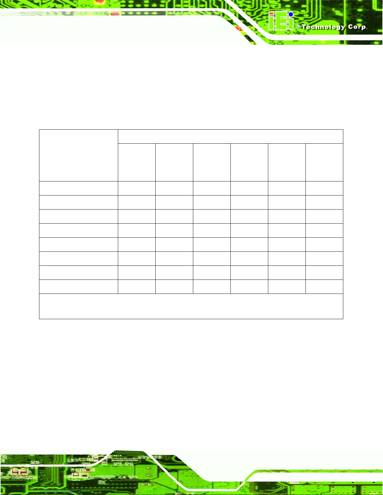
1.5 Technical Specifications
VWBOX-E133 video box features are listed in 295HTable 1-1. See Chapter 2 for details.
Specification Detail
Model Name
Main Features
Inputs
Outputs
Dimensions (W x D x H)
Cooling
Input Resolution
Output Resolution
VWBOX-E133
1. Multiple viewing modes
2. Software OSD
3. Remote control
4. Bezel masking
One DVI-D single link
Nine DVI-D single link
295 mm x 190 mm x 65 mm (71.4mm with rubber feet)
Fan
800x600, 1024x768, 1152x864, 1280x768, 1280x960,
1280x1024, 1600x1200, 1680x1050, 1920x1200
1024 x 768, 1360 x 768, 1280 x 1024, 1400 x 1500,
1680 x 1050, 1600 x 1200, 1920 x 1200, 1366 x 768,
1920 x 1080 (with auto scaling up to 3072x2304,
4080x2304, 3840x3072, 4200x3150, 4980x3150,
Power Adapter Input
Power Adapter Output
4800x3600, 5760x3600)
90 VAC to 264 VAC / 47 Hz to 63 Hz
12 V / 3.33 A / 40 W
Page 13
Page 14

Specification Detail
VWBOX-E133 Video Wall Controller
Safety and Emission
Temperature
Power Consumption
Table 1-1: Technical Specifications
CCC, CE, FCC
0ºC – 40ºC
35 W
Page 14
Page 15

VWBOX-E133 Video Wall Controller
1.6 Dimensions
Height: 65 mm (71.4mm with rubber feet)
Width: 295 mm
Depth: 190 mm
Figure 1-4: VWBOX-E133 Dimensions
Page 15
Page 16

VWBOX-E133 Video Wall Controller
Chapter
2
2 Unpacking List
Page 16
Page 17

VWBOX-E133 Video Wall Controller
2.1 Anti-static Precautions
WARNING:
Failure to take ESD precautions during the installation of the
VWBOX-E133may result in permanent damage to the
VWBOX-E133and severe injury to the user.
Electrostatic discharge (ESD) can cause serious damage to electronic components,
including the VWBOX-E133. Dry climates are especially susceptible to ESD. It is therefore
critical that whenever the VWBOX-E133 or any other electrical component is handled, the
following anti-static precautions are strictly adhered to.
Wear an anti-static wristband: Wearing a simple an ti-static wristband can
help to prevent ESD from damaging the board.
Self-grounding: Before handling the board, touch any grounded conducting
material. During the time the board is handled, frequently touch any
conducting materials that are connected to the ground.
Use an anti-static pad: When configuring the VWBOX-E133, place it on an
antic-static pad. This reduces the possibility of ESD damaging the
VWBOX-E133.
Only handle the edges of the PCB: When handling the PCB, hold the PCB
by the edges.
2.2 Unpacking Precautions
When the VWBOX-E133 is unpacked, please do the following:
Follow the anti-static precautions outlined in Section
Make sure the packing box is facing upwards so the VWBOX-E133 does not
fall out of the box.
Make sure all the components shown in Section
296H2.1.
297H2.3 are present.
Page 17
Page 18

2.3 Packing List
NOTE:
If some of the components listed in the checklist below are missing,
please do not proceed with the installation. Contact the IEI reseller or
vendor that sold the VWBOX-E133 from or contact an IEI sales
representative directly. To contact an IEI sales representative, please
VWBOX-E133 Video Wall Controller
send an email to
The VWBOX-E133 is shipped with the following components:
No. Description Image
1 VWBOX-E133
1 Power cord (European illustrated here)
1 Power adapter
1 Single-link DVI-D cable
142Hsales@iei.com.tw.
1 Remote control
1 Mounting brackets
1 Screw kit
Page 18
Page 19

VWBOX-E133 Video Wall Controller
No. Description Image
1 User manual CD
Table 2-1: Package List Contents
2.4 Optional Items
The following optional items are available for the VWBOX-E133:
No. Description Image
1 Single-link DVI-D cable
Table 2-2: Package List Contents
Page 19
Page 20

VWBOX-E133 Video Wall Controller
Chapter
3
3 Installation
Page 20
Page 21

VWBOX-E133 Video Wall Controller
3.1 Installation Overview
The VWBOX-E133 supports 4-panel, 6-panel, 9-panel, 36-panel (requires five video
boxes) and 81-panel setups (requires ten video boxes).
3.1.1 Four (2x2) Panel Overview
The implementation of a 4-panel (2x2) array is shown in 298HFigure 3-4 below.
Figure 3-1: Four (2x2) Panel Setup
Page 21
Page 22

3.1.2 Six (2x3) Panel Overview
The implementation of a 6-panel (2x3) array is shown in 299HFigure 3-4 below.
VWBOX-E133 Video Wall Controller
Figure 3-2: Six (2x3) Panel Setup
Page 22
Page 23

VWBOX-E133 Video Wall Controller
3.1.3 Six (3x2) Panel Overview
The implementation of a 6-panel (3x2) array is shown in 300HFigure 3-4 below.
Figure 3-3: Six (3x2) Panel Setup
Page 23
Page 24

3.1.4 Nine (3x3) Panel Overview
The implementation of a 9-panel (3x3) array is shown in 301HFigure 3-4 below.
VWBOX-E133 Video Wall Controller
Figure 3-4: Nine Panel Setup
Page 24
Page 25

VWBOX-E133 Video Wall Controller
3.1.5 36 Panel, Multi-controller Installation Overview
The implementation of a 36-panel array using one VWBOX-E133 as the master device
and nine VWBOX-E122 controllers as slave devices is shown in
302HFigure 3-5 below. Each
VWBOX-E122 slave controller connects to four display panels. Refer to the
VWBOX-E122 User Manual for installation guides to connect the controller in a 2x2 array.
Figure 3-5: 36 Panel Setup
Page 25
Page 26

VWBOX-E133 Video Wall Controller
3.1.6 81 Panel, Multi-controller Installation Overview (VWBOX-133A
Master controller)
The implementation of an 81-panel array using one VWBOX-133A as the master device
and nine VWBOX-E133 controllers as slave devices is shown in
VWBOX-E133 slave controller connects to nine display panels in a 3x3 array.
303HFigure 3-5 below. Each
Figure 3-6: 81 Panel Setup With VWBOX-133A Master Controller
3.2 Installation Steps
To install the VWBOX-E133 please follow the installation steps below:
Page 26
Page 27
VWBOX-E133 Video Wall Controller
Step 1: Install the LCD panels.
Step 2: Mount the VWBOX-E133.
Step 3: Connect DVI output cables, video input cable (DVI-D), RS-232 cable and power
adapter to the VWBOX-E133.
Step 4: Adjust the screen resolution output settings.
Step 5: Select a screen mode for display output.
Step 6: Adjust the VWBOX-E133 mask settings to align the images.Step 0:
3.3 Install LCD Panels
The LCD panels are installed as a square array, with two rows and two columns, for a total
of four monitors.
Recommended installation procedures are to
Use all identical monitors
Keep gaps between panels as small as possible for the best image
Keep all horizontal gaps between monitors in the array consistent
Keep all vertical gaps between monitors in the array consistent
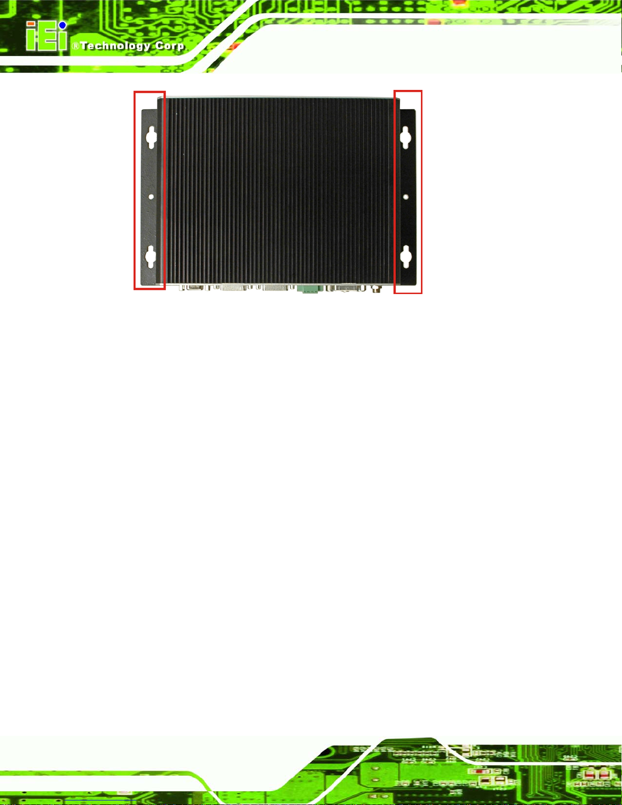
3.4 Mounting
The VWBOX-E133 must be placed on a table, desk or other firm surface. Optionally, the
VWBOX-E133 can be mounted using the included mounting brackets. The installation
location must be:
Out of direct sunlight
Without anything on top of it
On a firm surface
Away from moisture and liquids
Page 27
Page 28
VWBOX-E133 Video Wall Controller
Figure 3-7: Mounting Brackets
3.5 Connect Cables
The cables that need to be attached are listed below and their connections are shown in
304HFigure 3-8:
DVI-D input cable – from the video source or computer to the VWBOX-E133
DVI-D output cables – from the VWBOX-E133 to the LCD panels or other
slave video box controllers. Make sure the cables are connected to the correct
monitors as shown in
Power cable – from the power adapter
RS-232 cable (optional) – connected to a computer with smartOSD software
installed
305HFigure 3-8.
Page 28
Page 29

VWBOX-E133 Video Wall Controller
Figure 3-8: Cable Connections
3.5.1 Connect the Video Source and VWBOX-E133
Connect the video source to the VWBOX-E133. If the video source is a computer with the
smartOSD software installed, that computer can be used to adjust the monitor settings
without using the OSD.
The video source connects directly to the VWBOX-E133 through a DVI-D single link cable.
To connect the video source to the VWBOX-E133, follow the steps below.
Page 29
Page 30

VWBOX-E133 Video Wall Controller
Step 1: Attach the DVI video cable to the DVI output of the video source.
Step 2: Attach the DVI video cable to the DVI input on the VWBOX-E133.Step 0:
Figure 3-9: VWBOX-E133 Video Input
3.5.2 Connect the RS-232 Cable to the VWBOX-E133 (Optional)
The VWBOX-E133 has a male DB-9 connector on the rear panel. The RS-232 cable
connects to a computer that has the smartOSD software installed. This enables the
computer to control the screen setup. If the video source is from a PC the image screen
setup can be controlled through the DVI cable. Follow the steps below to connect a serial
device to the VWBOX-E133.
Step 1: Locate the DB-9 connector. The location of the DB-9 connector is shown in
Chapter 3.
Step 2: Insert the serial connector. Insert the DB-9 connector of a serial device into
the DB-9 connector on the external peripheral interface. See
306HFigure 3-10.
Page 30
Page 31

VWBOX-E133 Video Wall Controller
Figure 3-10: Serial Device Connector
Step 3: Secure the connector . Secure the serial device connector to the external
interface by tightening the two retention screws.Step 0:
3.5.3 Connect the VWBOX-E133 to the Power Supply
Connect the included PSU into an AC power supply then connect the PSU to the
VWBOX-E133. The figure below shows the typical setup. There is no power switch, and
the VWBOX-E133 turns on as soon as it is connected to the PSU.
3.6 Input and Output Resolution
Correct adjustment of the input and output resolutions gives a much better quality final
image. Follow the steps outlined in the subsections below to get the best image quality
from the video wall controller.
3.6.1 Screen Ratio
With auto-scaling it is not necessary to match the input and output aspect ratios.
Page 31
Page 32

3.6.2 Input Resolution
Input resolution should be set as high as possible. Pick a resolution that meets the
following criteria:
Matches the LCD panel aspect ratio (as shown in Error! Reference source not
found.)
Is the maximum possible (without exceeding input resolution limits)
3.6.3 Output Resolution
The output resolution should be set as high as possible, and meet the following criteria for
best results:
Matches video input and LCD panel resolution ratios
Is the maximum possible
VWBOX-E133 Video Wall Controller
Has a minimum width greater than half input width
Has a minimum height greater than half input height
3.7 Display Mode
There are five display mode options available. The display mode can be set through the
smartOSD (
307H4.2.2.2) or OSD menu (308H4.3.1). The modes are shown in 309HFigure 3-11 below.
Page 32
Page 33

VWBOX-E133 Video Wall Controller
Figure 3-11: Display Mode
Page 33
Page 34

VWBOX-E133 Video Wall Controller
Chapter
4
4 OSD Functions
Page 34
Page 35

VWBOX-E133 Video Wall Controller
4.1 Mask Setup
process, allowing the masking to be adjusted simultaneously from a single controller. For
a setup with one controller and four panels the horizontal and vertical gaps are easily
adjusted according to the installation. With a master controller and four slave controllers,
the mask setup remains just a simple. While adjusting the master controller, all the slave
controllers are automatically adjusted, making setup time up to five times faster then
individually setting up each video controller.
The GeniMask masking control
allows images to be adjusted slightly
larger than the visible screen size, to
compensate for the gaps between
panels. GeniMask simplifies this
Use either the smartOSD (
4.2 smartOSD
IEI smartOSD is a proprietary On-Screen-Display (OSD) software solution from IEI that
enables easy, remote monitor setting adjustments in a Windows environment. IEI
smartOSD delivers excellent performance and provides more flexibility than the typical
OSD hardware solutions when adjusting a monitor. smartOSD also allows the screen
output screen resolution and mask size to be adjusted using the DVI connection.
4.2.1 Pre-installation Notice
Before installing smartOSD software, please make sure one of the following operating
systems is installed:
Windows 95
Windows NT 4.0
Windows 98
310H4.2.2.2) or OSD menu (311H4.3.4.1) to set the mask value.
Windows 2000
Windows 2003
Windows XP
Windows Vista
Page 35
Page 36

4.2.2 Software Illustration
The table below shows the smartOSD menu structure (312HTable 4-1).
Menu Options
Interface Interface Selection
Display Display Resolution
Setting Digital I/O Test (for VWBOX-E122 only)
VWBOX-E133 Video Wall Controller
Display Mode
Mask Setting
Input Source
Power
Factory Reset
OSD Lock
About Company Contact Details
Table 4-1: smartOSD Menu Structure
Page 36
Page 37

VWBOX-E133 Video Wall Controller
4.2.2.1 Interface Page
The interface page is for choosing the interface between the computer and the
VWBOX-E133.
Figure 4-1: smartOSD Interface Page
Î Interface Select
The Interface Select option selects the data communication method between the
computer and the VWBOX-E133. If the computer also provides the video input, then
communication can be done over the DVI cable. Serial ports can also be used for data
communication. The dropdown list shows all communications ports by default. The
following are shown for reference, as the exact ports available are system dependent.
Î
DDC2Bi
Î
COM1
Î
COM3
DVI input
First serial port
Third serial port
Page 37
Page 38

4.2.2.2 Display Page
The Display Page adjusts the configuration of the panels in the video wall array.
VWBOX-E133 Video Wall Controller
Figure 4-2: smartOSD Display Page
Î Display Resolution
The Display Resolution setting shows the resolution of the video image output. Display
output setting options are shown below.
1024 x 768 @ 60 MHz
1360 x 768 @ 60 MHz
1280 x 1024 @ 60 MHz
1400 x 1050 @ 60 MHz
1680 x 1050 @ 60 MHz
1600 x 1200 @ 60 MHz
1920 x 1200 @ 60 MHz
1366 x 768 @ 60 MHz
1920 x 1080 @ 60 MHz
Page 38
Page 39

VWBOX-E133 Video Wall Controller
Î Display Mode
The display mode option configures how the image is displayed on the screen.
Î
1 x 1 DEFAULT
Î
2 x 2
Î
2 x 3
Î
3 x 2
Î
3 x 3
Î Mask Mode
Mask mode toggles the masking function.
Î
Off
Î
On DEFAULT
The video input is cloned on all the monitors
The video input is tiled over all the panels.
The video input is split across a six-panel array in a 2 x 3
setup
The video input is split across a six-panel array in a 3 x 2
setup
The video input is split across a nine-panel array in a 3 x 3
setup
The video box doesn’t compensate for gaps betwee n LCD p anels
The video box compensates for the gaps between LCD panels
Î H Mask %
The horizontal mask compensates for the horizontal gap between panels. Enter the bezel
width (mm) and viewable width (mm) into the corresponding data box to calculate the
correct figure.
Î V Mask %
The vertical mask compensates for the vertical gap between panels. Enter the bezel
height (mm) and viewable height (mm) into the corresponding data box to calculate the
correct figure.
Page 39
Page 40

4.2.2.3 Setting Page
VWBOX-E133 Video Wall Controller
Figure 4-3: smartOSD Setting Page
Î GPIO
The GPIO settings are for the VWBOX-E122 only.
Î Input Source
The input video source is automatically selected by the VWBOX-E133.
Î
DVI
Î Power
The power option turns the VWBOX-E133 on and off. Select one of the options below.
Î
On
Input video source is DVI
The video box displays the video source image onto the video
Page 40
outputs.
Page 41

VWBOX-E133 Video Wall Controller
Î
Off
Î Factory Mode
Factory mode resets the VWBOX-E133 to default settings. Two options are available for
resetting the values.
Î
Factory Default
Î OSD Mode
Two sets of options are available. The lock/unlock option sets whether the front panel
OSD buttons can be used for adjusting settings. The normal/rotation option sets the
onscreen OSD to a horizontal or vertical position.
Î
Lock
Î
Unlock
The video box is in standby mode. No images are displayed on the
video outputs, but the video box is ready to receive data commands.
Resets the video box to the factory defaults.
The front panel OSD buttons cannot be used to adjust settings
The front panel OSD buttons can be used to adjust settings
Page 41
Page 42

4.2.2.4 About Page
The About Page displays contact information. The smartOSD logo links to the IEI website.
VWBOX-E133 Video Wall Controller
Figure 4-4: smartOSD About Page
4.2.3 Install Software
To install the software, please follow the steps below:
Step 1: Follow the instructions from the interactive installer to install the IEI smartOSD
on the system.
Step 2: Insert the installation disk that came with the system and open the installation
file.
Step 3: The welcome screen shown below appears.
Page 42
Page 43

VWBOX-E133 Video Wall Controller
Figure 4-5: smartOSD Setup Wizard
Step 4: Click Next to continue.
Step 5: The screen below appears.
Figure 4-6: smartOSD Select Installation Folder
Page 43
Page 44

Step 6: Select the installation folder from the screen shown above.
Step 7: Click Next to continue.
Step 8: The screen shown below appears.
VWBOX-E133 Video Wall Controller
Figure 4-7: smartOSD Confirm Installation
Step 9: Confirm the installation by clicking Next in the screen above.
Step 10: The program starts to install and the progress bar shown below appears.
Page 44
Page 45

VWBOX-E133 Video Wall Controller
Figure 4-8: smartOSD Installing
Step 11: When the installation is complete the screen below appears.
Figure 4-9: smartOSD Installation Complete
Step 12: Click Close in the screen above.
Page 45
Page 46

Step 13: After quick setup is complete, the IEI smartOSD wizard logo appears on the
desktop as shown in the screen below.
Step 14: To access the smartOSD, click the smartOSD wizard logo on the desktop.
Step 0:
4.2.4 T roubleshooting
For troubleshooting, please see the steps below:
4.2.4.1 Windows 2000 Installation Failure
Installation fails under Windows 2000 and shows the following image:
VWBOX-E133 Video Wall Controller
Figure 4-10: DLL Missing
Solution: Download and install service pack Windows Installer 3.1
Page 46
Page 47

VWBOX-E133 Video Wall Controller
4.2.4.2 Vista Installation Failure
Installation fails under Vista while showing following image:
Figure 4-11: Windows Vista Error
Solution: Install smartOSD.exe as the administrator authority
Figure 4-12: Install as Administrator
Page 47
Page 48

4.3 Using the OSD
The OSD menu functions are described below.
4.3.1 OSD Buttons
There are several on-screen-display (OSD) control buttons oriented either verti cally on the
right side of the monitor front panel or on the bottom of the monitor front panel.
482H482H313HFigure 4-13 shows a typical arrangement of OSD controls.
VWBOX-E133 Video Wall Controller
Figure 4-13: OSD Buttons
Power. Turns the video box on and off.
Menu/Enter. Enters the OSD, selects items and sets the new values entered.
Left. Moves the selection left.
Right. Moves the selection right.
Up. Moves the selection up.
Down. Moves the selection down.
Auto/Exit. Exits from any menu.
4.3.2 OSD Lock
The OSD front panel buttons can be locked using the OSD lock function. To turn the OSD
lock on and off, follow the steps below. (The OSD can also be locked using the
smartOSD).
Step 1: Push the “Right” and “Auto/Exit” buttons simultaneously for a few second s.
Step 2: The OSD display shows the current status as locked or unlocked. Step 0:
Page 48
Page 49

VWBOX-E133 Video Wall Controller
4.3.3 Menu Structure
The table below shows the OSD menu structure.
Menu Options / Submenu Options
Display Output
Display Mode
Mask -> Horizontal Mask
Vertical Mask
Mask On/Off
Setting Factory
Information
Input -> DVI
Component
Miscellaneous -> OSD -> OSD Timer
OSD Rotation
Identify
Table 4-2: OSD Menu Structure
Page 49
Page 50

4.3.4 Display Menu
Image menu options are shown in 484H484H314HFigure 4-14 and described below.
VWBOX-E133 Video Wall Controller
Figure 4-14: Display Menu
Î Display Resolution
The Display Resolution setting shows the resolution of the video image output. Display
output setting options are shown below.
1024 x 768 @ 60 MHz
1360 x 768 @ 60 MHz
1280 x 1024 @ 60 MHz
1400 x 1050 @ 60 MHz
1680 x 1050 @ 60 MHz
1600 x 1200 @ 60 MHz
1920 x 1200 @ 60 MHz
1366 x 768 @ 60 MHz
1920 x 1080 @ 60 MHz
Page 50
Page 51

VWBOX-E133 Video Wall Controller
Î Display Mode
The display mode option configures how the image is displayed on the screen.
Î
1 x 1 DEFAULT
Î
2 x 2
Î
2 x 3
Î
3 x 2
Î
3 x 3
Î Mask Control
The Mask control compensates for the gaps between monitors in the video wall array.
These settings are shown in
The video input is cloned on all the monitors
The video input is tiled over all the panels.
The video input is split across a six-panel array in a 2 x 3
setup
The video input is split across a six-panel array in a 3 x 2
setup
The video input is split across a nine-panel array in a 3 x 3
setup
315H4.3.4.1.
Page 51
Page 52

4.3.4.1 Mask Control
The mask control menu adjusts the mask settings. The mask settings compensate for the
gaps between monitors in the video wall array. The mask control options are shown and
described below.
VWBOX-E133 Video Wall Controller
Figure 4-15: Mask Control
Î Horizontal Mask
Set the horizontal mask according to the formula in
Î Vertical Mask
Set the vertical mask according to the formula in
316HFigure 4-16.
317HFigure 4-16.
Page 52
Page 53

VWBOX-E133 Video Wall Controller
Figure 4-16: Mask Formula
Î Mask Control
The mask control option turns the mask control on and off.
Î
Off DEFAULT
Î
On
The video box doesn’t compensate for the gap between monitors
The video box compensates for the gap between monitors
Page 53
Page 54

4.3.5 System Menu
System menu options are shown in 485H485H318HFigure 4-17 and described in the subsections below.
VWBOX-E133 Video Wall Controller
Figure 4-17: Display Menu
Î Factory Reset
Factory reset returns all the settings to the factory default settings.
Î Information
Shows video box version information. The information details are shown in
Î Input Select
Input select allows selection of the input source. Input selection is shown in
Î Misc
Misc allows other OSD features to be adjusted. Misc options are shown in
319H4.3.5.1.
320H4.3.5.2.
321H4.3.5.3.
Page 54
Page 55

VWBOX-E133 Video Wall Controller
Î Identify Monitors
Identify monitors displays the monitor’s ID within the monitor array.
4.3.5.1 Information
The information screen in 322HFigure 4-18 shows some basic information about the video box
and the monitor. The details are described below.
Figure 4-18: Information Screen
Model name, firmware version and date
Input type
Video box ID (identifies the current video box in a larger array of video boxes)
Page 55
Page 56

4.3.5.2 Input Select
The input select screen in 323HFigure 4-19 shows the input options.
VWBOX-E133 Video Wall Controller
Figure 4-19: Input Select
The video box automatically selects the correct input source setting. The following options
are available.
DVI
Page 56
Page 57

VWBOX-E133 Video Wall Controller
4.3.5.3 Miscellaneous
The miscellaneous menu (324HFigure 4-20) allows the option to go to the OSD setup menu.
Figure 4-20: Input Select
Î OSD Configuration
OSD configuration adjusts the display settings for the OSD display. OSD configuration
settings are shown in
325H4.3.5.3.1.
Page 57
Page 58

VWBOX-E133 Video Wall Controller
4.3.5.3.1 OSD Configuration
The OSD configuration menu (326HFigure 4-21) adjusts the rotation of the OSD, and how long
it displays for.
Figure 4-21: Input Select
Î OSD Timer
The OSD Timer sets how long the OSD screen stays on after the last button press.
Page 58
Page 59

VWBOX-E133 Video Wall Controller
4.4 Remote Control
The VWBOX-E133 comes with a remote control for easy configuration of OSD settings.
491H491H327HFigure 4-22 shows the remote control and its function keys.
Figure 4-22: Remote Control
Power. Turns the video box on and off.
Menu/Enter. Enters the OSD, selects items and sets the new values entered.
Left. Moves the selection left.
Right. Moves the selection right.
Up. Moves the selection up.
Down. Moves the selection down.
Auto/Exit. Exits from any menu.
Page 59
Page 60

VWBOX-E133 Video Wall Controller
Chapter
5
5 Troubleshooting and
Maintenance
Page 60
Page 61

VWBOX-E133 Video Wall Controller
WARNING:
Take Anti-Static precautions whenever maintenance is being carried
out on the embedded system components. Failure to take anti-static
precautions can cause permanent embedded system damage.
5.1 Anti-static Precautions
WARNING:
Failure to take ESD precautions during the installation of the
VWBOX-E133 may result in permanent damage to the VWBOX-E133
and severe injury to the user.
Electrostatic discharge (ESD) can cause serious damage to electronic components,
including theVWBOX-E133. Dry c limates are especially susceptible to ESD. It is therefore
critical that whenever the VWBOX-E133 or any other electrical component is handled, the
following anti-static precautions are strictly adhered to.
Wear an anti-static wristband: Wearing a simple an ti-static wristband can
help to prevent ESD from damaging the board.
Self-grounding: Before handling the board or opening the embedded syste m,
touch any grounded conducting material. During the time the board is ha ndled,
frequently touch any conducting materials that are connected to the ground.
Use an anti-static pad: When configuring theVWBOX-E133, place it on an
antic-static pad. This re duces the possibility of ESD damaging
theVWBOX-E133.
Only handle the edges of the PCB: When handling the PCB, hold the PCB
by the edges.
Page 61
Page 62

5.2 Maintenance Overview
NOTE:
There are no user-serviceable parts inside. Make sure to carefully
follow all the instructions in this section to diagnose any problems. If
VWBOX-E133 Video Wall Controller
the problem persists, email
representative
To preserve the working integrity of the VWBOX-E133 embedded system, the embedded
system must be properly maintained. If embedded system components need repl acement,
the proper maintenance procedures must be followed to ensure the embedded system
can continue to operate normally.
5.3 Troubleshooting
This section provides some simple troubleshooting suggestions.
5.3.1 No Image on One Monitor
If there is no image on one monitor, follow these steps to remedy the problem.
5.3.1.1 Check Monitor Power
143Hsales@iei.com.tw for help from an IEI sales
Step 1: Check that the monitor is turned on.
Step 2: Check that the power source for the monitor is turned on.
Step 3: Check that the power source has the correct power rating (check panel
specifications for details).
Step 4: Make sure the LCD panel power cables are securely fastened to the monitor and
to the power source.Step 0:
5.3.1.2 Check Panel Video Connection
Check to see that the video cable is fitted correctly.
Page 62
Page 63

VWBOX-E133 Video Wall Controller
Step 1: Check that the monitor is connected to the VWBOX-E133.
Step 2: Securely attach the video cable to the panel and to the VWBOX-E133.
Step 3: Fasten the video cable at both ends and tighten the video cable screws.Step 0:
5.3.2 No Image Two or Three Monitors
If there is no image on more than one of the panels, then repeat the steps in Section 328H5.3.1
for all of the monitors in the array.
5.3.3 No Image on Any Monitor
If no image displays on any monitors, repeat the steps in Section 329H5.3.1 for all the monitors
in the array, then try the following additional steps.
5.3.3.1 Check Video Box Power
Make sure that the video box is powered on.
Step 1: Check the power supply is connected to the power source.
Step 2: Check that the VWBOX-E133 is connected to the power supply.Step 0:
5.3.3.2 Check Source Video Connection
Check to that the source video cable is securely connected to the VWBOX-E133.
Step 1: Securely attach the video cable from the video source to the VWBOX-E133.
Step 2: Fasten the video cable at both ends and tighten the video cable screws. Step 0:
Page 63
Page 64

VWBOX-E133 Video Wall Controller
Appendix
A
A RS-232 Setup
Page 64
Page 65

VWBOX-E133 Video Wall Controller
A.1 Setup
The serial port is used to remotely set and get the settings from the VWBOX-E133. The
serial port is used by user applications to change the settings of the VWBOX-E133
through a software interface. The serial port should be setup as indicated in
Description Setting
Baud rate 115200
Parity Non-parity
Data bit 8
Stop bit 1
Flow control None
Table 5-1: RS-232 Setup
A.2 Packet Format
The generalized format of a single data packet on the RS-232 communications port is
shown in
section.
331HTable 5-2. The specific setup details for all the commands are shown in the next
330HTable 5-1
Byte Function
[1] The number of bytes in the signal
[2] This byte indicates the command to perform
[3]-[n-1]* These bytes contain the data needed for the com mand
[n]* Checksum byte
Table 5-2: n-Byte Data Output Format
* n indicates the number of bytes (length) of the data packet. This value depends on the
command that is being used.
Page 65
Page 66

A.3 Command Reference
This section details the commands that can be sent over the RS-232 communi cations port.
The following commands are detailed:
144HGet display status...................................................................................332H67
145HGet factory defaults................................................................................333H68
146HSet mask control ....................................................................................334H69
147HSet display mode....................................................................................335H70
148HSet display resolution.............................................................................336H70
149HSet input source.....................................................................................337H71
150HSet power control...................................................................................338H71
151HSet to default..........................................................................................339H72
152HSet OSD mode.......................................................................................340H72
VWBOX-E133 Video Wall Controller
Page 66
Page 67

VWBOX-E133 Video Wall Controller
A.3.1 Get Display Status
Byte Value
[1]
[2]
[3]
[4]
0x08
0x03
Output resolution:
0 – 1024 x 768
1 – 1360 x 768
2 – 1280 x 1024
3 – 1400 x 1500
4 – 1680 x 1050
5 – 1600 x 1200
6 – 1920 x 1200
7 – 1366 x 768
8 – 1920 x 1080
Output display mode
0 – 1 x 1 mode
1 – 2 x 2 mode
2 – 2 x 3 mode
3 – 3 x 2 mode
4 – 3 x 3 mode
[5]
[6]
[7]
[8]
Table 5-3: Get Display Status
Mask control
0 – Off
1 – On
Horizontal mask percent
0 – 10%
Vertical mask percent
0 – 10%
Checksum
0xff-([1]+[2]+[3]+[4]+[5]+[6]+[7]+[9])
Page 67
Page 68

A.3.2 Get Factory Defaults
Byte Value
VWBOX-E133 Video Wall Controller
[1]
[2]
[3]
[4]
[5]
[9]
Table 5-4: Get Factory Defaults
0x09
0x04
Input source
2 - DVI
Power
0 – Power off
1 – Power on
OSD lock/unlock
0: OSD unlock
1: OSD lock
Checksum
0xff-([1]+[2]+[3]+[4]+[5]+[6]+[7]+[8]+[9])
Page 68
Page 69

VWBOX-E133 Video Wall Controller
A.3.3 Set Mask Control
Byte Value
[1]
[2]
[3]
[4]
[5]
[6]
0x07
0x18
Display mode
0 – 1 x 1 mode
1 – 2 x 2 mode
2 – 2 x 3 mode
3 – 3 x 2 mode
4 – 3 x 3 mode
Horizontal mask percent
0 – 10%
Vertical mask percent
0 – 10%
Mask control
0 – Off
1 – On
[7]
Table 5-5: Set Mask Control
0xff-([1]+[2]+[3]+[4]+[5]+[6])
Page 69
Page 70

A.3.4 Set Display Mode
Byte Value
VWBOX-E133 Video Wall Controller
[1]
[2]
[3]
[4]
Table 5-6: Set Display Mode
0x04
0x19
Display mode
0 – 1 x 1 mode
1 – 2 x 2 mode
2 – 2 x 3 mode
3 – 3 x 2 mode
4 – 3 x 3 mode
0xff-([1]+[2]+[3])
A.3.5 Set Display Resolution
Byte Value
[1]
0x04
[2]
[3]
[4]
Table 5-7: Set Display Resolution
0x1A
Output resolution
0 – 1024 x 768
1 – 1360 x 768
2 – 1280 x 1024
3 – 1400 x 1500
4 – 1680 x 1050
5 – 1600 x 1200
6 – 1920 x 1200
7 – 1366 x 768
8 – 1920 x 1080
0xff-([1]+[2]+[3])
Page 70
Page 71

VWBOX-E133 Video Wall Controller
A.3.6 Set Input Source
Byte Value
[1]
[2]
[3]
[4]
Table 5-8: Set Input Source
0x04
0x1B
Input source
2 - DVI
0xff-([1]+[2]+[3])
A.3.7 Set Power Control
Byte Value
[1]
[2]
[3]
0x04
0x1C
Power control
0 – power off
1 – power on
[4]
Table 5-9: Set Power Control
0xff-([1]+[2]+[3])
Page 71
Page 72

A.3.8 Set to Default
Byte Value
VWBOX-E133 Video Wall Controller
[1]
[2]
[3]
[4]
Table 5-10: Set to Default
A.3.9 Set OSD Mode
Byte Value
[1]
[2]
[3]
0x04
0x01
Defaults
0 – auto adjust
1 – factory defaults
0xff-([1]+[2]+[3])
0x04
0x02
OSD Mode
0 – OSD unlock
Page 72
1 – OSD lock
4 – OSD ID information
[4]
Table 5-11: Set OSD Mode
0xff-([1]+[2]+[3]+[4])
Page 73

VWBOX-E133 Video Wall Controller
B DDC2BI Setup
Appendix
B
Page 73
Page 74

B.1 Introduction
The DDC2BI setup is for reading and setting the video box options through a DVI cable
connected to the VWBOX-E133 from the video source.
B.2 Command Reference
The digital I/O port is for external machines to read and write settings to the
VWBOX-E133.
Code VCP Code Names Type Description
B0h Display Resolution Read/Write 0 – 1024x768
VWBOX-E133 Video Wall Controller
1 – 1360x768
2 – 128x1024
3 – 1400x1050
4 – 1680x1050
5 – 1600x1200
6 – 1920x1200
7 – 1366 x 768
8 – 1920 x 1080
B1h Display Mode Read/Write 0 – 1x1
1 – 2x2
2 – 2x3
3 – 3x2
4 – 3x3
B2h Mask Mode Read/Write H percent – high byte
V percent – low byte
Mask control (bit 8)
0 – off
1 – on
ECh Auto Adjust Write o nly 1 – automatically adjust
D6h Power Mode Read/Write 0 – Power On
Page 74
the settings
1 – Power Off
Page 75

VWBOX-E133 Video Wall Controller
Code VCP Code Names Type Description
60h Video Source Read/Write 2 – DVI
14h Factory reset Write only 1 – reset to factory
FCh OSD Mode Read/Write 0 – OSD Unlock
F8h Get Model ID Read only word: Model ID
Table 5-12: Set Power Control
defaults
1 – OSD Lock
2 – OSD Normal
Ox801:E133
Page 75
Page 76

VWBOX-E133 Video Wall Controller
Appendix
C
C Terminology
Page 76
Page 77

VWBOX-E133 Video Wall Controller
COM
DIO
DVI
GPIO
LCD
LVDS
COM refers to serial ports. Serial ports offer serial communication to
expansion devices. The serial port on a person al computer is usually a
male DB-9 connector.
The digital inputs and digital outputs are general control signals that
control the on/off circuit of external devices or TTL devices. Data can be
read or written to the selected address to enable the DIO functions.
The Digital Video Interface st andard allows analog and digital video
transmission
General purpose input/output
Liquid crystal display (LCD) is a flat, low-power display device that
consists of two polarizing plates with a liquid crystal panel in between.
Low-voltage differential signaling (LVDS) is a dual-wire, high-speed
differential electrical signaling system commonly used to connect LCD
displays to a computer.
Page 77
Page 78

VWBOX-E133 Video Wall Controller
Appendix
D
D Hazardous Materials
Disclosure
Page 78
Page 79

VWBOX-E133 Video Wall Controller
D.1 Hazardous Materials Disclosure Table for IPB Products
Certified as RoHS Compliant Under 2002/95/EC Without
Mercury
The details provided in this appendix are to ensure that the product is compliant with the
Peoples Republic of China (China) RoHS standards. The table below acknowledges the
presences of small quantities of certain materials in the product, and is appli cable to China
RoHS only.
A label will be placed on each product to indicate the estimated “Environmentally Friendly
Use Period” (EFUP). This is an estimate of the number of years that these substances
would “not leak out or undergo abrupt change.” This product may contain replaceable
sub-assemblies/components which have a shorter EFUP such as batteries and lamps.
These components will be separately marked.
Please refer to the table on the next page.
Page 79
Page 80

Toxic or Hazardous Substances and Elements Part Name
VWBOX-E133 Video Wall Controller
Housing
Display
Printed Circuit
Board
Metal
Fasteners
Cable
Assembly
Fan Assembly
Power Supply
Assemblies
Lead
(Pb)
X O O O O X
X O O O O X
X O O O O X
X O O O O O
X O O O O X
X O O O O X
X O O O O X
Mercury
(Hg)
Cadmium
(Cd)
Hexavalent
Chromium
(CR(VI))
Polybrominated
Biphenyls
(PBB)
Polybrominated
Diphenyl
Ethers
(PBDE)
Battery
O: This toxic or hazardous substance is containe d in all of the homog eneous mate rials for the p a rt is
below the limit requirement in SJ/T11363-2006
X: This toxic or hazardous substance is contained in at least one of the homogeneous materials for
this part is above the limit requirement in SJ/T11363-2006
O O O O O O
Page 80
Page 81
VWBOX-E133 Video Wall Controller
此附件旨在确保本产品符合中国 RoHS 标准。以下表格标示此产品中某有毒物质的含量符
合中国 RoHS 标准规定的限量要求。
本产品上会附有”环境友好使用期限”的标签,此期限是估算这些物质”不会有泄漏或突变”的
年限。本产品可能包含有较短的环境友好使用期限的可替换元件,像是电池或灯管,这些元
件将会单独标示出来。
部件名称
壳体
显示
印刷电路板
金属螺帽
电缆组装
风扇组装
电力供应组装
电池
O: 表示该有毒有害物质在该部件所有物质材料中的含量均在 SJ/T11363-2006 标准规定的限量要求以下。
X: 表示该有毒有害物质至少在该部件的某一均质材料中的含量超出 SJ/T11363-2006 标准规定的限量要求。
有毒有害物质或元素
铅
(Pb)
X O O O O X
X O O O O X
X O O O O X
X O O O O O
X O O O O X
X O O O O X
X O O O O X
O O O O O O
汞
(Hg)
镉
(Cd)
六价铬
(CR(VI))
多溴联苯
(PBB)
多溴二苯
醚
(PBDE)
Page 81
 Loading...