

Page 1

TRADEMARKS
VioGate TM and IEI® are trademarks of ICP Electronics Inc.
Microsoft
®
, Windows® and Internet Explorer® are registered trademarks of Microsoft Inc. All other
brand or product names are trademarks of their respective companies or organizations.
LIMITED WARRANTY
In no event shall IEI’s liability exceed the price paid for the product from direct, indirect, special,
incidental, or consequential software, or its documentation. IEI offers no refunds for its products. IEI
makes no warranty or representation, expressed, implied, or statutory, with respect to its products or the
contents or use of this documentation and all accompanying software, and specifically disclaims its
quality, performance, merchantability, or fitness for any particular purpose. IEI reserves the right to
revise or update its products, software, or documentation without obligation to notify any individual or
entity.
FCC STATEMENT
The IEI VioGate has been tested and found to comply with the limits for a Class B digital device,
pursuant to Part 15 of the FCC Rules. These limits are designed to provide reasonable protection
against harmful interference in a residential installation. This equipment generates, uses, and can
radiate radio frequency energy and, if not installed and used according to the instructions, may cause
harmful interference to radio communications. However, there is no guarantee that interference will not
occur in a particular installation. If this equipment does cause harmful interference to radio or
television reception, which is found by turning the equipment off and on, the user is encouraged to try
to correct the interference by one or more of the following measures:
z Reorient or relocate the receiving antenna
z Increase the separation between the equipment or device
z Connect the equipment to an outlet other than the receiver’s
z Consult a dealer or an experienced radio/TV technician for assistance
IMPORTANT NOTE
Read Instructions
Before the unit is operated, please read all the safety and operating instructions.
Power Sources
Only operate this unit with the type of the power source specified by the manufacturer.
Servicing
Please contact qualified technicians for any service requests. Do not attempt to service the unit yourself,
as opening the cover may expose you to dangerous voltage and other hazards.
Warning
To prevent fire or shock, do not expose this equipment to rain or moisture.
Do not place heavy items on the unit.
1
Page 2

Overview of the VioGate
About VioGate Server
With the VioGate embedded system, any authorized user can view live video-feeds
and play back recorded video files remotely through the help of Internet.
System administrator can also use IE browser to complete various system settings
through a user-friendly and powerful web-interface.
Main Features
- Surveillance over IP. (Plug and Play)
- Can operate in standalone mode, or with a VioGate Master to create a
complete network surveillance system.
- Superior image quality (30 fps max for one camera)
- Support up to 4 surveillance cameras
- Support Dome PTZ camera
- Retaining up to 30 seconds of digital images before the alarm is triggered.
- Support 1/16x to 16x playback speed.
- Support Multicast Mode
- Use IE(version 5.0 or above)to quickly complete the first time setup
- Support remote system software upgrade
System Requirements
- Black and white or color camera(NTSC or PAL standard)
- Networking Requirements
RJ-45 Ethernet cable,and a dynamic or static IP address
- Client side personal computer requirements
Pentium II or above desktop or laptop computer
64MB of RAM
VGA card (Recommended resolution: 1024x768 pixels)
Microsoft Windows 98 SE or above
Internet Explorer version 5.0 or above
(In Internet Options, Security level for this zone has be set to Medium or
less)
Package Contents
2
Page 3

The VioGate box contains:
z VioGate IP Surveillance Server
z User’s Manual
z Power Cord
z One CAT-5 Ethernet Cable
z Quick Install Wizard (CD-ROM or Floppy Diskette)
System Overview
VioGate 100
z Front View
Configuration Reset Switch
Configuration Reset Switch
Configuration Reset Switch
Configuration Reset Switch
Network Indicator
Network Indicator
Network Indicator
Network Indicator
Power Indicator
Power Indicator
Power Indicator
Power Indicator
z Rear View
VGA Port
VGA Port
VGA Port
VGA Port
RJ-45 Network
RJ-45 Network
RJ-45 Network
RJ-45 Network
GPIO Connector
GPIO Connector
GPIO Connector
GPIO Connector
RS-232 Port
RS-232 Port
RS-232 Port
RS-232 Port
Video Input Connector
Video Input Connector
Video Input Connector
Video Input Connector
Keyboard & Mouse
Keyboard & Mouse
Keyboard & Mouse
Keyboard & Mouse
Power Connector
Power Connector
Power Connector
Power Connector
Rs-422/485 Port
Rs-422/485 Port
Rs-422/485 Port
Rs-422/485 Port
Power Switch
Power Switch
Power Switch
Power Switch
Remark: The “VGA Port” and the “Keyboard & Mouse” connectors are only used by
technical personnel to maintain the server.
3
Page 4

Installation of the VioGate
Default Network Configuration of the VioGate
By default, the VioGate server is set up to obtain its IP address and other TCP/IP
network protocol settings from a DHCP server. If no DHCP server is found on the
network, the VioGate server will use the following default settings instead:
IP Address: 192.168.0.1
Subnet Mask: 255.255.255.0
Administrator Account Name: administrator
Administrator Account Password: admin
Note: Before you modify any of the network settings, please press down on the
configuration reset switch. (Use a sharp object to press down on the configuration
reset switch located in the front of the VioGate server for 5 seconds. You will hear 5
beeps when the reset has been completed)
Installing the VioGate
Local Area Network (DHCP IP)
1. Please prepare a network cable and connect the VioGate server to the LAN.
2. Turn on VioGate server.
3. Please run the VioGate Finder utility in the accompanying CD.
4
Page 5

4. Please click on the “Refresh” button located at the bottom of the window.
5. If there are several VioGate servers in your LAN, please choose the correct device
and double-click on the device entry.
6. If you can connect to the VioGate server successfully, the webpage will
automatically prompt you for the user name and the password. Please enter the
default username and password:
User Name: administrator
Password: admin
Notice: If you wish to connect to the VioGate server remotely via Internet, your
VioGate server needs to have a public IP.
Local Area Network (Fixed IP)
1. Please connect the VioGate server to the Hub or Router in your LAN.
2. Please run the VioGate Finder utility located in the accompanying CD.
3. Select the server you wish to configure.
4. Click on “Configure” to configure the server.
5. Enter the username and password (the default password is “admin”)
5
Page 6

6. Enter the TCP/IP networking setting.
6
Page 7

6. Click on “OK” and restart the VioGate server.
7. Start the web-browser and enter the VioGate’s IP address in the location field.
Notice: If you wish to connect to the VioGate server remotely via Internet, your
VioGate server needs to have a public IP.
ADSL Connection (Dynamic IP)
1. If your VioGate server connects to the Internet through ADSL (i.e. uses dynamic
IP), then you will need to utilize the Dynamic DNS service in order to connect to
the VioGate server remotely. Please register for an account name on
www.dyndns.org please to obtain a username, password and a domain name.
(For a detail step-by-step tutorial, please refer to Appendix B)
2. Please refer to “Connect a Personal Computer with the VioGate” section to
connect the VioGate server to the personal computer.
3. Please click on the setting icon located on the left of the screen. Within the setup
page, choose the “Network Settings” and select the “Use broadband connection
to the Internet (PPPoE)” option, and enters the user name and password used to
connect to the ADSL.
4. Check the “Enable Dynamic DNS Service” box, and enter the user name,
password, and host name information. Select the “dynamic IP address” option.
5. Click on the “OK” button. Note that after you click on the “OK” button, you
have to wait a few seconds before the VioGate server restarts the networking
configuration.
6. Please restart the VioGate server.
7. Please restore your personal computer’s network settings, and use a network
cable to connect the VioGate server and the modem.
8. Enter the host name you have registered at www.dyndns.org in the web browser.
If you can connect to the VioGate server administration page, it means that you
have completed the VioGate server’s network settings successfully.
7
Page 8

Using VioGate
Monitoring Page
After you’ve setup the VioGate server’s network setting and successfully connected to
the network, you can use your web browser (Microsoft Internet Explorer version 5.0
or above; using version 5.5 is recommended) to use the monitoring function.
Enter the Monitoring Page
Users can use the following 2 ways to connect to your VioGate server’s monitoring
page.
1. Start the web browser, if you know the IP address of the VioGate server,
please enter the IP address in the web browser’s location field, and press
Enter.
2. Start the accompanying VioGate Finder utility,and double-click on the
desired server entry listed
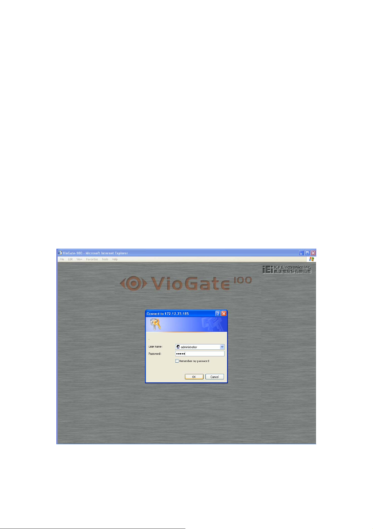
When the browser displays the VioGate login page, please enter the username and
password to login to VioGate.
8
Page 9

After the user has successfully logged in to the server, he should see the following
monitoring page.
(If the monitoring page fails to display correctly, you can attempt to refresh the page
after shutting down your anti-virus software)
Options
Display Mode
You can select the desired display mode for the monitoring page, please use the
function keys located on the left of the monitoring page to select the desired display
mode.
View Single Camera
Adjust Window Size
Full-Screen Mode
9
Page 10
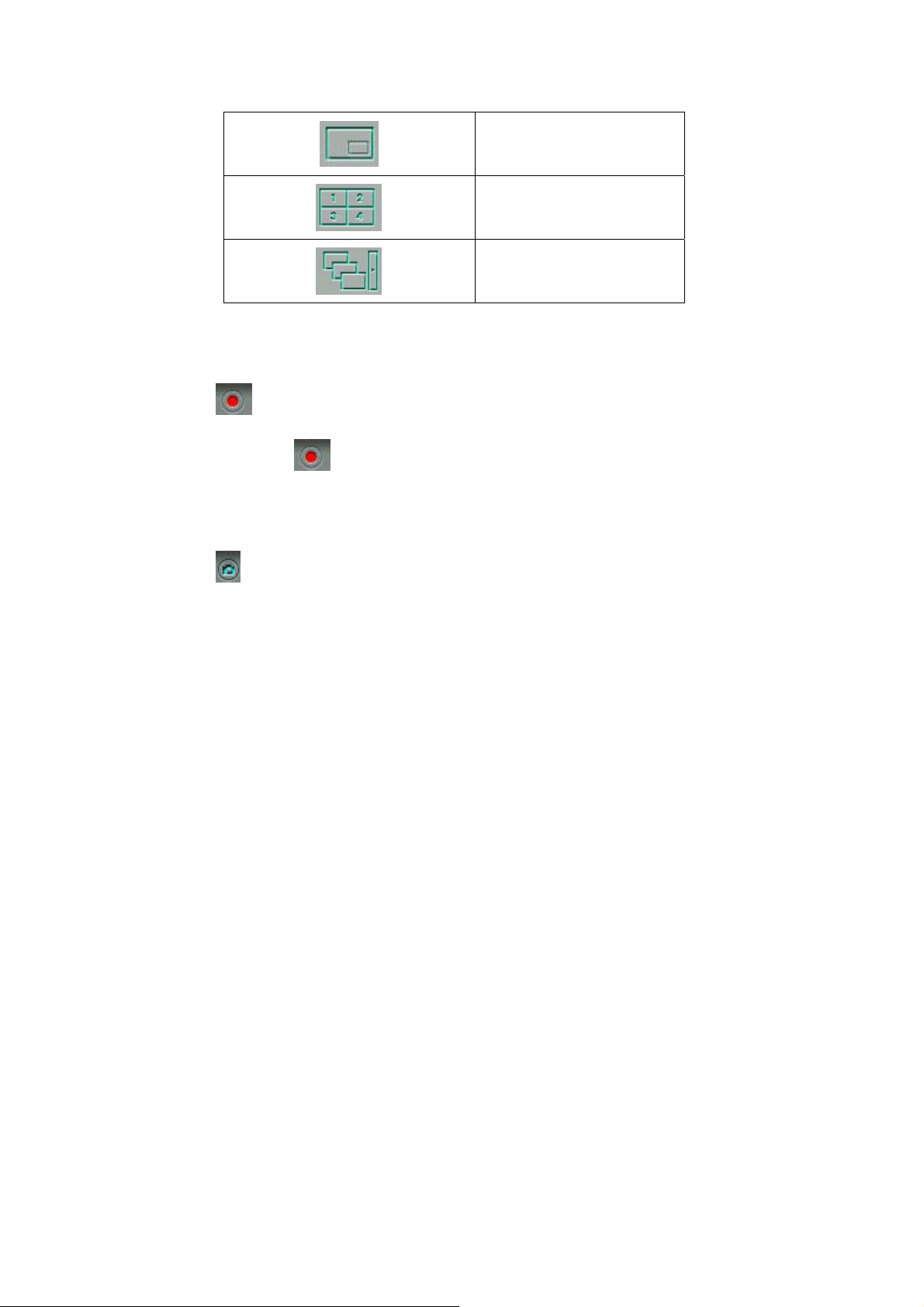
Picture in Picture Mode
Quad Mode
Sequential Mode
Recording Videos
Press the button to record the selected camera’s live video to the local personal
computer. Press the button again to stop the recording.
Take Snapshots
Press the button to save a snapshot image file to the local personal computer.
Other Messages
When the server cannot display live video for a particular camera, the corresponding
video window will display an error message, possible messages are listed below:
z Connecting
If Multicast is enabled, it may take longer to establish a connection.
z Connection Failure
Please make sure that the network cable between the camera and the server is
connected, and the network settings are configured properly.
z No Signal
Please check the connection between the camera and the server to clear this
problem
z No Privilege
The account used to log in to the server does not have the privilege required to
view the camera, please re-login to the server using a user account with proper
privileges.
Video Playback
10
Page 11

Please press the button in the monitoring page or the administration page to
enter the video playback page.
Select Video Files
You can use the following ways to select the video files to playback:
Select files stored on the remote storage device
according the time.
Select files recorded due to the triggering of certain
events.
Select files stored on the local personal computer.
Save Video Files
You can press the button after you’ve selected some files stored on the remote
storage device to store the files to your personal computer.
11
Page 12

Play Video Files
While you are using the video playback function to playback the video files, you can
use the following controls:
z Play
z Stop
z Frame by Frame
z Select playback rate
12
Page 13
Configuring VioGate
Once you have installed the VioGate and other hardware, and connected it to the network,
you can use your browser (only supports Microsoft Internet Explorer 5.0 or later;
Microsoft Internet Explorer 5.5 is recommended) to complete administrative tasks for the
VioGate.
Accessing the Administration Page
The user can connect to the VioGate administration page through the following 2
methods:
1. Start the web browser; if you know the VioGate server’s IP address, please
enter the IP address in the location field and press the Enter key.
2. Run the included VioGate Finder utility program, and double-click on the
server you wish to configure in the list of servers acquired.
When the web browser connects to the VioGate server administration page, it will
prompt you for the administrator’s username and password. Enter the correct
information to continue the administration process.
The default administrator account information is as follows:
User name: administrator
Password: admin
13
Page 14

After you’ve successfully logged in to the server, please click on the located
on the left hand side of the administration page to enter the quick-configuration page.
Server Administration
The Server Administration comprises the following eleven sections:
14
Page 15

Administration
Server Administration
DQuick Configuration
DSystem Settings
DServer Name
DSoftware Version
DDate & Time
DNetwork Settings
DUsing DHCP
DUsing Fixed IP
DUsing PPPoE
DEnable DynDNS Service
DSpecify DNS Server
DEnable Multicast
DIP Security
DAllow All Connection
DAllow Connections Only from the Following List
DDeny Connections from the Following List
DUser Management
DUsers
DUser Privileges
DCamera Settings
DBasic Settings
DAdvanced Video Settings
DPTZ Camera Settings
DRecording Settings
DEnable Recording
DDisable Recording
DSnapshot Settings
DEnable Snapshot
DDisable Snapshot
DEvent Handling
DEvent Type
DEvent Action Settings
DStatistics & Logs
DActive Users
DHistorical Users
DEvent Logs
DSystem Tools
DSystem Update
DBackup/Restore
DRestart/Shutdown
DHardware
15
Page 16

Quick Configuration
When you start the VioGate server for the first time, you can follow Quick
Configuration’s 9 steps to finish basic VioGate server configuration. Following details
the 9 steps involved in the Quick Configuration setup.
1. Enter the name and description of this server.
2. Change the password of the administrator.
3. Set up the network configuration.
4. Adjust the time settings.
5. Add the users to access this server.
6. Assign the descriptive name for each camera.
7. Configure the recording settings.
8. Configure the snapshot settings.
9. Quick configuration complete.
Depends on the variations on the server configuration, the system setup can take from
3 minutes to 10 minutes to finish.
System Settings
Configure the server name and time.
You can setup some basic information about the system such as the server name, date
and time. You can also verify the current software version in this page.
Server Name
You have to choose a unique system name for your VioGate server so that it can be
identified quickly on the network. System name can contain up to 20 characters,
consisting of the usual Alpha-numeric characters, dash (-) and Chinese characters.
Also, you can assign a short description text for your VioGate server. (An example of
the description might be the administrator’s name, department name, or the location
of the server). When other users use the VioGate Finder utility to locate VioGate
servers located within the same subnet, they will see this short description. The
description text can contain up to 126 characters, consisting of the usual
Alpha-numeric characters, dash (-) and Chinese characters.
Date and Time
Please select the correct time zone according the location of the server, and adjust the
16
Page 17

date and time accordingly. If you enter invalid date and time setting you might
encounter the following problems:
1. If you are using the browser to view the live video feed, the time displayed
within the video feed might be out of sync with the time on your personal
computer.
2. Incorrect date and time information will be displayed when you try to play back
some video files or view the event logs.
Network Settings
Select the method the VioGate server uses to connect o the network, and decides
whether to enable the multicast function. You need to understand the configuration of
your network to enter the correct setting. If you are uncertain about how your server
connects to the external network or have question on any of the TCP/IP setting in
general, please contact your network administrator for further assistance.
Obtain IP address settings automatically (DHCP)
Often used in conjunction with Cable Modem and corporate networks, the system will
obtain IP address and other TCP/IP information automatically. If your network
supports Dynamic Host Configuration Protocol, the VioGate server will obtain the IP
address and other TCP/IP information automatically from the DHCP server.
Assign IP address settings manually
Use the specified IP address setting. Often used in ADSL permanent connection
service. You have to manually specify the IP address and other setting. If the server’s
external network uses ADSL service to connect to the internet, please specify the
valid IP address supplied by your ISP (Internet Service Provider). You have to enter
the following settings:
IP address
IP address is a sequence of binary number normally represented by 4 numbers
separated by periods, and is used to uniquely identify a server on the network.
Subnet Mask
Subnet Mask is used to group computers belonging to the same local area
network. Similar to IP address, it’s normally represented by 4 numbers separated
by periods.
Gateway
17
Page 18

If the VioGate server connects to the Internet through the broadband service,
please use the gateway IP address supplied by your ISP. If your network is a
LAN to LAN network, please contact your network administrator to configure
the correct gateway IP address to connect to other network segment. If you do
not wish to setup any gateway, please set this value to 0.0.0.0.
Use broadband connection to the Internet (PPPoE)
PPPoE is often used in dial-up ADSL broadband service. You have to use the account
username, and password provided by your ISP to connect to the Internet successfully.
Use DHCP if failed to connect
If the server fails to connect to the internet using the PPPoE protocol, it will
attempt to obtain IP address information through DHCP service.
Enable Dynamic DNS service
If you wish to let users on the internet to use a domain name to connect to the VioGate
server, you can activate the dynamic domain name service. Please apply for an
account and register for a dynamic domain name at a dynamic domain name service
provider. (For detail information, please refer to appendix B). After you’ve registered
a dynamic domain name and complete the setup, your VioGate server will
automatically update the dynamic IP address information with the service provider’s
server. What follows is the detail description on the various fields configurable.
Username, Password, Server Name
Please enter the information you provided when you open an account on the
dynamic domain name service provider’s website.
Dynamic IP Address or Static IP Address
If your VioGate server connects to the Internet through a permanent ADSL
connection, then you will obtain a set of static IP address from your ISP. You can
then choose to use static IP address when you are registering a dynamic domain
name. If on the other hand, your VioGate server connects to the Internet through
a dial-up ADSL or Cable Modem connection, your IP address is dynamically
assigned. Please choose the correct IP address type when you are registering for
the dynamic domain name. For a more detailed description, please refer to the
help page on the dynamic domain server provider’s website.
Specify DNS server.
If you wish to assign a specific DNS server, please enter its IP address here.
Enable Multicast
Using multicast allows the server to simultaneously send a message to multiple clients.
18
Page 19

If you wish to enable Multicast, please enter Group IP Address and Port number here.
IP Security
You can use this function to create a connection list that the system uses to decide
whether to accept of deny connection from a particular network or specific IP. You
can choose one of the following 3 options to restrict access to the server:
Allow all connections
All connections to the server will be allowed
Allow connections only from the following list
The server will only accept connections made by computers within the list
Deny connections from the following list
The server will only deny connections made by computers within the list
The factory setting of the VioGate server is to “Accept All Connections”
User Management
Your VioGate server can provide services to any authorized user. To effectively
manager different user’s privileges, you have to register and configure user accounts
and account privileges.
The system includes the following built-in account name and password. You will not
be able to delete or rename this account.
Account name: administrator
Password: admin
You can create new user depending on your need. You have to provide the following
information when creating a new user.
Username
The user name can contain up to 32 characters. The username is case-insensitive, can
contain double-byte characters (for example, Chinese, Japanese, Korean), but cannot
contain the following characters:
" / \ [ ] : ; | = , + * ? < > ` ' %
Password
19
Page 20

The password can contain up to 16 case-sensitive characters. For security reason, you
should choose a password with at least 6 characters long that is not easy to be
guessed.
You can perform the following user account administration tasks:
z Create a new user
z Change password for a user
z Change an account name
z Change user privileges
z Remove one ore more users
Camera Settings
You can perform the following preference setting for your camera:
z Specify camera name
z Adjust image resolution
z Select image compression ration
z Select image capturing rate
You can perform the following addition image settings in the advance image setting
page:
z Brightness
z Contrast
z Hue
z Saturation
P/T/Z Camera
PTZ(Pan、Tilt、Zoom)Camera can Pan, Tilt, Zoom and change its focus. If you wish
to enable camera’s PTZ functionalities, please enable the function through the
webpage, and provide the following information:
z Dome ID
z Mode
z Protocol
Recording Settings
Before you enable recording function, the live video feed you see on the web page
will not be saved. You have to enable the recording function to save the video files
20
Page 21

before you can use the video play-back function.
Recording mode
z Continuous Recording
The system will continuously record the video feed to the storage, but other
setting might cause the server to stop recording
z Scheduled Recording
The system will start the recording function according to the day, staring time
and the ending time that you’ve specified.
Storage Setting
Please choose any of the following storage type, and enter respective information
according to the storage type.
z NAS
z Windows
z Unix/Linux
z FTP
Storage Path
The recording storage path is the path used by the recording function to store video
files. The snapshot storage path is the path used by the snapshot functions to store
snapshots. Please enter these 2 paths in order to manage the 2 different files
conveniently.
Note: If you save the video files using the FTP service, please make sure you enter a
valid path that already exists. Otherwise you will not be able to save the files.
Handling “Storage Space Low” event
When the free storage space falls under a specified limit, you choose one of the
following handling methods. (If you choose to save files through FTP service, the
amount cannot be specified.)
z Overwrite the oldest recorded files
z Stop saving the newly recorded files
Note: When using the “Overwrite the oldest recorded files” option, your storage
device must able to store at least 2 hours worth of video files, which takes around 5Gb
of storage space to store.
21
Page 22

Snapshot Settings
Snapshot mode
z Snapshot Interval
You can setup the interval between the snapshots
z Continuous Snapshot
The systems will continuously takings snapshots, but other setting might cause
the server to stop recording
z Scheduled Snapshot
The system will start taking snapshots according to the day, starting time and the
ending time that you’ve specified.
Storage Setting
Please choose any of the following storage type, and enter respective information
according to the storage type.
z NAS
z Windows
z Unix/Linux
z FTP
Storage Path
The recording storage path is the path used by the recording function to store video
files. The snapshot storage path is the path used by the snapshot functions to store
snapshots. Please enter these 2 paths in order to manage the 2 different files
conveniently.
Note: If you save the image files using the FTP service, please make sure you enter a
valid path that already exists. Otherwise you will not be able to save the files.
Handling “Storage Space Low” event
When the free storage space falls under a specified limit, you choose one of the
following handling methods. (If you choose to save files through FTP service, the
amount cannot be specified.)
z Overwrite the oldest snapshot files
z Stop saving the newly snapshot files
22
Page 23

Note: When using the “Overwrite the oldest snapshot files” option, your storage
device must able to store at least 2 hours worth of video files, which takes around 5Gb
of storage space to store.
Event Handling
Event Type
When an event happens, the system will automatically trigger corresponding alarms,
react to unusual conditions, to ensure that the VioGate server can correctly capture,
record, and play back video files. Each event can be individually associated with
various alarms
z Motion Detection
z Video Input Loss
z Network Failure
z Hardware Failure
z Storage Connection Failure
z Storage Space Full
z GPIO Input (maximum of 4 GPIO devices)
Event Action Settings
You can perform multiple event actions for a single event, and connect GPIO devices
to generate alarms。
z Recording
z Snapshot
z Alert E-mail
z Alarm Buzzer
z GPIO Output (maximum of 4 GPIO devices)
Statistics and Logs
You can view a list of active user, historical users and event logs as a reference for the
system administrator or for system diagnostic purpose.
Active Users
Display information about all currently active users online
23
Page 24

Historical Users
Display information about all users ever connected to the system
Event Logs
Display all information, warning, and error event logs.
System Tools
You can use the following system tools to conveniently configure and manage your
VioGate server.
System Update
Perform system software updates. Please ensure the correctness of the update image
file before proceeding with the update.
Backup/Restore
You can backup your current system settings, user accounts information to your
computer. You can also perform the restore operation using a previously backed-up
file, or reset the system to its default factory setting.
Restart/Shutdown
Choose “Restart” to restart or shutdown the VioGate server. If you choose to
shutdown the system, please turn off the power switch located on the back of the
VioGate server.
Hardware
Choose to enable or disable the hardware Configuration Reset Switch. The default
setting is to “Enable”. If it is enabled, the system administrator account’s password
and network configuration will be reset to their default values when the user presses
down on the rest button for 5 seconds. In addition, the server will accept all
connections if the configuration reset switch is pressed.
24
Page 25

VioGate Viewer
If you choose to record image files using the VioGate server, the server will
automatically save video files (with .ivg as the extension) to the specified storage
device. The video files will have following filename format: yyyy-mm-dd
hh-mm-ss.ivg. You can connect to the server and copy the video files to your personal
computer and launch the VioGate Viewer to view the file content.
Installing VioGate Viewer
Please launch the setup program on the included CD to install the VioGate Viewer,
after the installation is completed, the installation program will create a shortcut on
your desktop
Note: Installin VioGate Viewer will automatically install VioGate Finder as well.
Using VioGate Viewer
Double-click on the VioGate viewer shortcut to launch the VioGate Viewer. You
should see the following screen:
Play Video Files
1. Pleas use the “+” and ”-“ buttons to select and delete the video files you wish to
play.
25
Page 26

2. Use the function buttons located on the bottom left of the window to play, pause,
stop, and skip the video files.
3. Select the numbers located on the left hand side of the window to adjust the
playback speed.
4. Click on the right hand side button to change the window size.
26
Page 27

Maintenance
VioGate has been specially designed to run on 24 hours, 7 days a week and to be
ready at all times. It is also robust to protect against system crashes caused by power
loss. This section provides a general maintenance overview.
Shutdown/Restart the Server
To shutdown/restart the server, please open the administration web page and go to
System Tools – Restart. Follow the instructions to restart or shutdown the system.
Reset the Administrator Password & Network Settings
If you accidentally forget the administrator password, you will not be able to perform
any administration work on VioGate. Under this condition, you can reset the
administrator password and network configuration to the factory default.
1. Use the tip of a ball point pen and depress the configuration reset switch located
on the front of VioGate. Hold it for about 5 seconds until the beep.
2. The network configuration will be reset, and you may need to re-configure some
or all of the network settings.
3. Use a web browser to connect to VioGate. Enter the System Administration and
enter the following login name and password.
Login: Administrator
Password: admin
You can then perform system administration.
Note: If the configuration reset switch is disabled in the System Tools · Hardware
page, you are no longer able to use this function. Please remember your
administrator password.
Update the System
Enter the System Administration page by a web browser, and have the system updated
in the System Tools – System Update page. Before updating the system, please
make sure that the image file that you are about to update is the correct version and
read through the instruction carefully.
Restore the Configurations
To restore the configurations to the factory default, please use a web browser to
27
Page 28

connect to VioGate. Go to the system Administration and restore the configurations
in the System Tools – Backup/Restore page.
28
Page 29

Appendix A Terms and Glossary
TCP/IP
(Transmission Control Protocol/Internet Protocol)
TCP/IP was originally developed by the Defense Department of the US to allow
dissimilar computers to talk. Today, as many of us know, this protocol is used as the
basis for the Internet. Because it must span such large distances and cross multiple,
smaller networks, TCP/IP is a routable protocol,, meaning it can send data through a
router on its way to its destination. In the long run, this slows things down a little,
but this ability makes it very flexible for large networks
DCHP
(Dynamic Host Configuration Protocol)
It’s a method for assigning Internet Protocol (IP) addresses permanently or on the fly
to individual computers in an organization’s network. Usually is performed by a
DHCP server.
FTP
(File Transfer Protocol)
This is a method of moving files from system to system using TCP/IP with FTP
application.
DHCP IP
An address with numbers like the one in a static IP address is assigned to your
computer by your ISP’s server so that other computer servers can find your computer
when you are connected to the internet. This IP address changes because whatever
IP address is available at the time you log on is the one that you get.
Static IP
An address that is assigned to your computer that never changes. It’s a series of
numbers used to identify your computer and looks something like this: 185.182.12.4
PPPoE
(Point-to-Point Protocol over Ethernet)
The Point-to-Point Protocol over Ethernet (PPPoE) feature allows a PPP session to be
initiated on a simple bridging Ethernet connected client. The session is transported
29
Page 30

over the ATM link via encapsulated Ethernet-bridged frames. The session can e
terminated at either a local exchange carrier central office or an internet service
provider (ISP) point of presence.
DNS
(Domain Name System)
Domain Name System identifies each computer as a network node on the Internet
using an internet protocol address system to translate from domain name to IP
numbers and vice-versa.
DDNS
(Dynamic Domain Name System)
Dynamic DNS (DDNS) service enables clients and servers to automatically register
themselves in the database without needing administrators to manually define records.
30
Page 31

Appendix B Registering a Dynamic Domain Name
Introduction
Your VioGate supports the DDNS service provided by DynDNS. You can go to the web
site of DynDNS (http://www.dyndns.org/) and register for a dynamic domain name.
Configure and activate the DDNS service, then the Internet users will be able to access
your VioGate via this dynamic domain name. When the ISP assigns a new WAN IP
address, VioGate will update the new address to the DynDNS server automatically.
Registration Procedure
Please follow below steps to register a dynamic domain name:
Note: This guide is for reference only. If there are any changes, please refer to the
instructions or documents on the web site.
a. Open the browser and connect to http://www.dyndns.org. Click on “Sign Up
Now” to begin the registration process.
31
Page 32

b. Click on “Agree” if you accept the service agreement.
c. Enter the username, email address and password to create a DDNS service account.
You will need to enter the same username and password in the Network
Settings.DDNS Service page of the Disk On-line Server system administration.
Please verify your email address to receive the confirmation message from the
server. Then click on “Create Account” to proceed.
32
Page 33
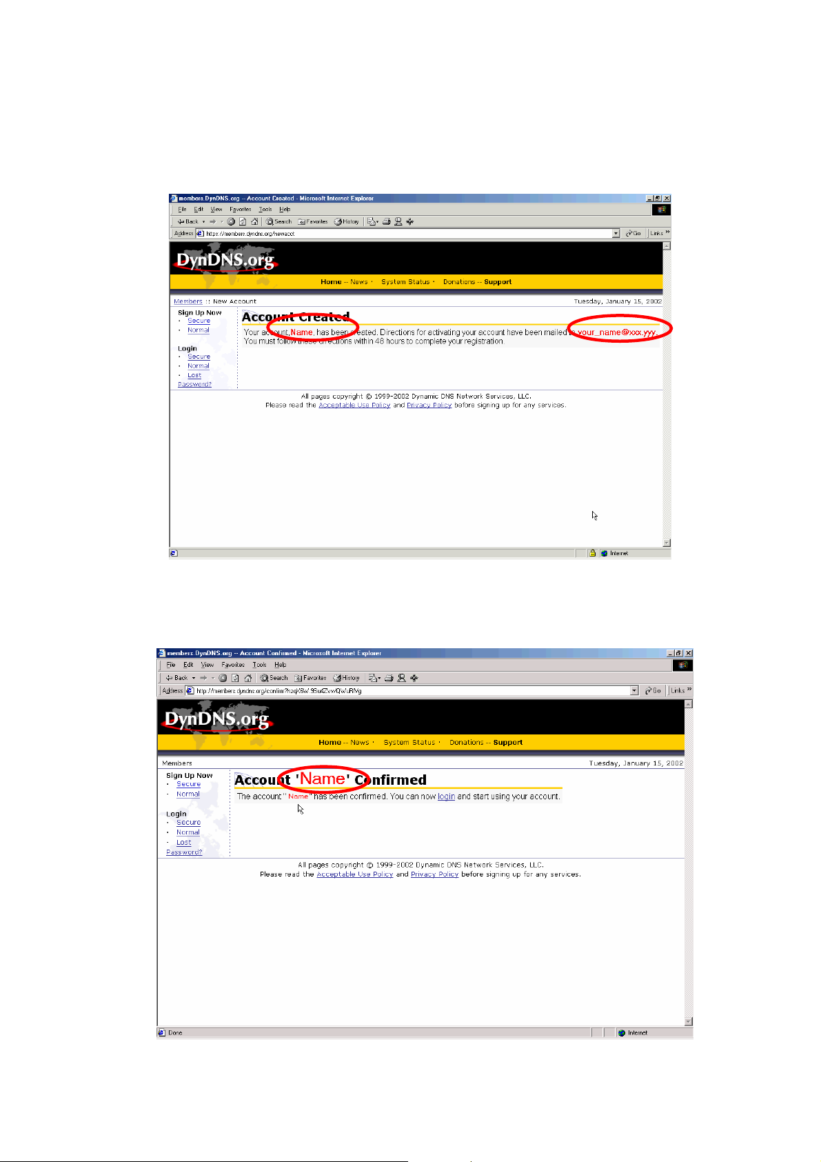
d. If below web page appears on the screen, your account has been successfully
created and a confirmation message has been sent to your -mail address. Please
follow the instructions in the e-mail to activate your account within 48 hours.
e. When you have finished the process of confirmation, a new screen will appear and
you can apply for your own dynamic domain name.
33
 Loading...