

IEI Technology uIBX-210-CV-N2600, uIBX-210-CV-N2600/2GB-R10, UIBX-210W -CV-N2600/2GB-R10 User Manual
Page 1
MODE L :
Fanless E mbedded System with Intel® Atom™ N2600
uIB X-210-CV-N2600 Embedded S ystem
,
uIB X-210-CV-N2600 S eries
DC 1.6G Hz, Intel® NM10 chipset, Pre-ins talled 2GB DDR 3
memory, VGA, HDMI, GbE , Four US B 2.0,
Three COM and R oHS Compliant
User Manual
R ev. 1.02 – 14 J une 2018
Page i
Page 2

uIB X-210-CV-N2600 Embedded S ystem
R evision
Date Version Changes
14 June 2018 1.02 Add Table 3-1: RS-422/485 Serial Port Pinouts
Add Table 3-2: RS-422/485 Connector Pinouts (DB-9)
28 February 2013 1.01 Update Section 2.3: Packing List
27 December 2012 1.00 Initial release
Page ii
Page 3

uIB X-210-CV-N2600 Embedded S ystem
COP YR IG HT NOTIC E
The information in this document is subject to change without prior notice in order to
improve reliability, design and function and does not represent a commitment on the part
of the manufacturer.
In no event will the manufacturer be liable for direct, indirect, special, incidental, or
consequential damages arising out of the use or inability to use the product or
documentation, even if advised of the possibility of such damages.
This document contains proprietary information protected by copyright. All rights are
Copyright
reserved. No part of this manual may be reproduced by any mechanical, electronic, or
other means in any form without prior written permission of the manufacturer.
TR ADEMARK S
All registered trademarks and product names mentioned herein are used for identification
purposes only and may be trademarks and/or registered trademarks of their respective
owners.
Page iii
Page 4

uIB X-210-CV-N2600 Embedded S ystem
Manual Conventions
WAR NING
Warnings appear where overlooked details may cause damage to the
equipment or result in personal injury. Warnings should be taken
seriously.
CAUTION
Cautionary messages should be heeded to help reduce the chance of
losing data or damaging the product.
NOTE
These messages inform the reader of essential but non-critical
information. These messages should be read carefully as any directions
or instructions contained therein can help avoid making mistakes.
HOT S URFACE
This symbol indicates a hot surface that should not be touched without
taking care.
Page i
Page 5

uIB X-210-CV-N2600 Embedded S ystem
Table of Contents
1 INTRODUCTION ........................................................................................................... 2
1.1 OVERVIEW ................................................................................................................... 3
1.2 MODEL VARIATIONS ..................................................................................................... 3
1.3 FEATURES ................................................................................................................... 4
1.4 TECHNICAL SPECIFICATIONS ........................................................................................ 4
1.5 FRONT PANEL .............................................................................................................. 6
1.6 REAR PANEL ................................................................................................................ 6
1.7 DIMENSIONS................................................................................................................ 8
2 UNPACKING .................................................................................................................. 9
2.1 ANTI-STATIC PRECAUTIONS ........................................................................................ 10
2.2 UNPACKING PRECAUTIONS ........................................................................................ 10
2.3 PACKING LIST ............................................................................................................. 11
3 INSTALLATION ........................................................................................................... 12
3.1 INSTALLATION PRECAUTIONS ..................................................................................... 13
3.2 INSTALLATION AND CONFIGURATION STEPS ................................................................ 13
3.3 WI-FI ANTENNA INSTALLATION (WI-FI MODEL ONLY) ................................................ 13
3.4 AT/ATX MODE SELECTION ........................................................................................ 14
3.4.1 AT Power Mode ................................................................................................ 15
3.4.2 ATX Power Mode ............................................................................................. 15
3.5 RESET THE SYSTEM .................................................................................................... 15
3.6 POWERING ON THE SYSTEM ....................................................................................... 16
3.7 MOUNT THE SYSTEM .................................................................................................. 16
3.7.1 Wall Mount ....................................................................................................... 17
3.7.2 VESA mount 75 ................................................................................................ 19
3.7.3 VESA mount 100 .............................................................................................. 22
3.8 EXTERNAL PERIPHERAL INTERFACE CONNECTORS ...................................................... 24
3.8.1 Audio Connection ............................................................................................. 26
3.8.2 HDMI Device Connection ................................................................................ 27
3.8.3 LAN Connection ............................................................................................... 28
Page ii
Page 6

uIB X-210-CV-N2600 Embedded S ystem
3.8.4 RS-232 Serial Port Connection ........................................................................ 29
3.8.5 RS-422/485 Serial Port Connection ................................................................. 30
3.8.6 USB Device Connection ................................................................................... 32
3.8.7 VGA Monitor Connection ................................................................................ 33
3.9 DRIVER DOWNLOAD .................................................................................................. 34
4 SYSTEM MOTHERBOARD ........................................................................................ 36
4.1 OVERVIEW ................................................................................................................. 37
4.1.1 Layout .............................................................................................................. 37
4.2 INTERNAL PERIPHERAL CONNECTORS......................................................................... 37
4.2.1 Battery Connector (BAT1) ............................................................................... 38
4.2.2 BIOS Programming Connector (SPI1) ............................................................ 38
4.2.3 Debug port Connector (DEBUGCN1) ............................................................. 38
4.2.4 HDD LED Connector (HDDLED1) ................................................................. 39
4.2.5 JSATA Connector (JSATA2) ............................................................................. 39
4.2.6 Power LED Connector (PWRLED1) ............................................................... 39
4.2.7 USB 2.0 Connector (USB4_5) ......................................................................... 40
4.2.8 SATA Connector (S_ATA1) ............................................................................... 40
4.2.9 SATA Power Connector (CN1) ......................................................................... 40
4.3 EXTERNAL INTERFACE PANEL CONNECTORS ................................................................ 41
4.3.1 Audio Jack (JAUDIO1) .................................................................................... 41
4.3.2 Ethernet Connector (LAN1) ............................................................................. 41
4.3.3 HDMI Connector (HDMI1) ............................................................................. 42
4.3.4 Power Connector (DC_JACK1) ...................................................................... 42
4.3.5 RS-232 Serial Ports (COM1, COM2) .............................................................. 42
4.3.6 RS-422/485 Serial Port (COM3) ..................................................................... 43
4.3.7 USB 2.0 Connectors (USB0_1) ........................................................................ 43
4.3.8 USB 2.0 Connector (USB23) ........................................................................... 43
4.3.9 VGA Connector (VGA1) ................................................................................... 43
4.4 JUMPER SETTINGS ..................................................................................................... 44
4.4.1 AT/ATX Mode Select Jumper (J_AUTOPWR1) ............................................... 44
5 SYSTEM MAINTENANCE ......................................................................................... 45
5.1 SYSTEM MAINTENANCE INTRODUCTION ...................................................................... 46
5.2 ANTI-STATIC PRECAUTIONS ........................................................................................ 46
Page iii
Page 7

5.3 TURN OFF THE POWER ............................................................................................... 47
5.4 REPLACING COMPONENTS ......................................................................................... 47
5.4.1 Hard Disk Drive (HDD) Replacement ............................................................. 47
5.4.2 Memory Module Replacement ......................................................................... 50
5.4.3 WLAN Card Replacement ................................................................................ 51
6 BIOS .............................................................................................................................. 54
6.1 INTRODUCTION ......................................................................................................... 55
6.1.1 Starting Setup ................................................................................................... 55
6.1.2 Using Setup ...................................................................................................... 55
6.1.3 Getting Help ..................................................................................................... 56
6.1.4 Unable to Reboot after Configuration Changes .............................................. 56
6.1.5 BIOS Menu Bar ................................................................................................ 56
6.2 MAIN ........................................................................................................................ 57
6.3 ADVANCED ................................................................................................................ 58
uIB X-210-CV-N2600 Embedded S ystem
6.3.1 ACPI Configuration ......................................................................................... 58
6.3.2 RTC Wake Settings ........................................................................................... 59
6.3.3 CPU Configuration .......................................................................................... 61
6.3.4 SATA Configuration ......................................................................................... 62
6.3.5 USB Configuration ........................................................................................... 63
6.3.6 F81866 Super IO Configuration ...................................................................... 64
6.3.6.1 Serial Port n Configuration ...................................................................... 65
6.3.7 F81866 H/W Monitor ....................................................................................... 68
6.3.8 Serial Port Console Redirection ...................................................................... 69
6.3.8.1 Console Redirection Settings .................................................................... 70
6.4 IEI FEATURE ............................................................................................................. 72
6.5 CHIPSET .................................................................................................................... 73
6.5.1 Host Bridge Configuration .............................................................................. 74
6.5.1.1 Intel IGD Configuration ........................................................................... 74
6.5.2 Southbridge Configuration .............................................................................. 75
6.6 BOOT ........................................................................................................................ 76
6.7 SECURITY .................................................................................................................. 79
6.7.1 HDD Security Configuration ........................................................................... 80
6.8 SAVE & EXIT ............................................................................................................. 81
A REGULATORY COMPLIANCE.................................................................................. 83
Page iv
Page 8

uIB X-210-CV-N2600 Embedded S ystem
B SAFETY PRECAUTIONS ........................................................................................... 89
B.1 SAFETY PRECAUTIONS ............................................................................................... 90
B.1.1 General Safety Precautions ............................................................................. 90
B.1.2 Anti-static Precautions .................................................................................... 91
B.1.3 Product Disposal ............................................................................................. 92
B.2 MAINTENANCE AND CLEANING PRECAUTIONS ............................................................ 92
B.2.1 Maintenance and Cleaning .............................................................................. 93
B.2.2 Cleaning Tools ................................................................................................. 93
C BIOS MENU OPTIONS .............................................................................................. 94
D WATCHDOG TIMER .................................................................................................. 97
E HAZARDOUS MATERIALS DISCLOSURE ........................................................... 100
Page v
Page 9

uIB X-210-CV-N2600 Embedded S ystem
Lis t of Figures
Figure 1-1: uIBX-210-CV-N2600 ..................................................................................................... 3
Figure 1-2: uIBX-210-CV-N2600 Front Panel ................................................................................ 6
Figure 1-3: uIBX-210-CV-N2600 Rear Panel ................................................................................. 7
Figure 1-4: Physical Dimensions (mm) ........................................................................................ 8
Figure 3-1: Wi-Fi Antenna Installation ........................................................................................14
Figure 3-2: AT/ATX Switch Location ...........................................................................................14
Figure 3-3: Reset Button Location ..............................................................................................16
Figure 3-4: Power Button Location .............................................................................................16
Figure 3-5: Wall-mounting Bracket .............................................................................................17
Figure 3-6: Chassis Support Screws ..........................................................................................18
Figure 3-7: Secure the uIBX-210-CV-N2600 ...............................................................................19
Figure 3–8: Panel PC (VESA 75 mm) ..........................................................................................19
Figure 3–9: Mount Kit Installation ...............................................................................................20
Figure 3–10: Slide the System .....................................................................................................20
Figure 3–11: Mount Kit Screws ...................................................................................................21
Figure 3–12: Stand Installation ...................................................................................................21
Figure 3–13: Panel PC (VESA 100 mm) ......................................................................................22
Figure 3–14: 100 mm to 75 mm Adapter ....................................................................................22
Figure 3–15: Mount Kit Installation .............................................................................................23
Figure 3–16: Slide the System .....................................................................................................23
Figure 3–17: Mount Kit Screws ...................................................................................................24
Figure 3–18: Stand Installation ...................................................................................................24
Figure 3-19: Peripheral Connectors (Front Panel) ....................................................................25
Figure 3-20: Peripheral Connectors (Rear Panel) .....................................................................26
Figure 3-21: Audio Connector .....................................................................................................27
Figure 3-22: HDMI Connection ....................................................................................................28
Figure 3-23: LAN Connection ......................................................................................................29
Figure 3-24: DB-9 Serial Port Connector ....................................................................................30
Figure 3-25: RS-422/485 Cable ....................................................................................................31
Figure 3-26: RS-422/485 Serial Port Connector .........................................................................31
Page vi
Page 10

uIB X-210-CV-N2600 Embedded S ystem
Figure 3-27: RS-422/485 Serial Port (DB-9) ................................................................................31
Figure 3-28: USB Device Connection .........................................................................................33
Figure 3-29: VGA Connector .......................................................................................................34
Figure 4-1: System Motherboard ................................................................................................37
Figure 5-1: Retention Screws Removal ......................................................................................47
Figure 5-2: HDD Bracket Retention Screws ...............................................................................48
Figure 5-3: HDD Bracket ..............................................................................................................48
Figure 5-4: HDD Retention Screws .............................................................................................49
Figure 5-5: Remove the old HDD .................................................................................................49
Figure 5-6: uIBX-210-CV-N2600 SO-DIMM Socket Location .....................................................50
Figure 5-7: DDR3 SO-DIMM Module Installation ........................................................................51
Figure 5-8: uIBX-210-CV-N2600 SO-DIMM Socket Location .....................................................52
Figure 5-9: Removing the Antennas ...........................................................................................52
Figure 5-10: Releasing the WLAN Card ......................................................................................53
Figure 5-11: Removing the WLAN card ......................................................................................53
Page vii
Page 11

uIB X-210-CV-N2600 Embedded S ystem
Lis t of Tables
Table 1-1: Model Variations ........................................................................................................... 3
Table 1-2: Technical Specifications .............................................................................................. 6
Table 2-1: Package List Contents ...............................................................................................11
Table 3-1: RS-422/485 Serial Port Pinouts .................................................................................31
Table 3-2: RS-422/485 Connector Pinouts (DB-9) .....................................................................32
Table 4-1: Peripheral Interface Connectors ...............................................................................38
Table 4-2: Battery Connector Pinouts (BAT1) ...........................................................................38
Table 4-3: BIOS Programming Connector Pinouts (SPI1) ........................................................38
Table 4-4: Debug port Connector Pinouts (DEBUGCN1) ..........................................................39
Table 4-5: HDD LED Connector Pinouts (HDDLED1) ................................................................39
Table 4-6: JSATA Connector Pinouts (JSATA2) .......................................................................39
Table 4-7: Power LED Connector Pinouts (PWRLED1) ............................................................39
Table 4-8: USB 2.0 Connector Pinouts (USB4_5) ......................................................................40
Table 4-9: SATA Connector Pinouts (S_ATA1) .........................................................................40
Table 4-10: SATA Power Connector Pinouts (CN1) ..................................................................40
Table 4-11: Rear Panel Connectors ............................................................................................41
Table 4-12: Audio Jack Pinouts (JAUDIO1) ...............................................................................41
Table 4-13: Ethernet Connector Pinouts (LAN1) .......................................................................42
Table 4-14: HDMI Connector (HDMI1) Pinouts ...........................................................................42
Table 4-15: Power Connector Pinouts (DC_JACK1) .................................................................42
Table 4-16: RS-232 Serial Ports Pinouts (COM1, COM2) ..........................................................43
Table 4-17: RS-422/485 Serial Port Pinouts (COM3) .................................................................43
Table 4-18: USB 2.0 Connectors Pinouts (USB0_1) ..................................................................43
Table 4-19: USB 2.0 Connector Pinouts (USB2_3) ....................................................................43
Table 4-20: VGA Connector Pinouts (VGA1) .............................................................................44
Table 4-21: Jumper .......................................................................................................................44
Table 4-22: AT/ATX Mode Select Jumper Settings (J_AUTOPWR1) .......................................44
Table 6-1: BIOS Navigation Keys ................................................................................................56
Page viii
Page 12

uIB X-210-CV-N2600 Embedded S ystem
B IOS Menus
BIOS Menu 1: Main .......................................................................................................................57
BIOS Menu 2: Advanced ..............................................................................................................58
BIOS Menu 3: ACPI Configuration ..............................................................................................59
BIOS Menu 4: RTC Wake Settings ..............................................................................................60
BIOS Menu 5: CPU Configuration ...............................................................................................61
BIOS Menu 6: IDE Configuration .................................................................................................62
BIOS Menu 7: USB Configuration ...............................................................................................63
BIOS Menu 8: Super IO Configuration........................................................................................64
BIOS Menu 9: Serial Port n Configuration Menu .......................................................................65
BIOS Menu 10: Hardware Health Configuration ........................................................................68
BIOS Menu 11: Serial Port Console Redirection .......................................................................69
BIOS Menu 12: Console Redirection Settings ...........................................................................70
BIOS Menu 13: iEi Feature ...........................................................................................................72
BIOS Menu 14: Chipset ................................................................................................................73
BIOS Menu 15: Northbridge Chipset Configuration ..................................................................74
BIOS Menu 16: Integrated Graphics ...........................................................................................75
BIOS Menu 17: Southbridge Chipset Configuration .................................................................76
BIOS Menu 18: Boot .....................................................................................................................76
BIOS Menu 19: Security ...............................................................................................................79
BIOS Menu 20: Security ...............................................................................................................80
BIOS Menu 21:Exit ........................................................................................................................81
Page 1
Page 13

uIB X-210-CV-N2600 Embedded S ystem
Chapter
1
1 Introduction
Page 2
Page 14

uIB X-210-CV-N2600 Embedded S ystem
1.1 Overview
Figure 1-1: uIBX-210-CV-N2600
The uIBX-210-CV-N2600 embedded system is a fanless system with one VGA port and
one HDMI port for dual display. It accepts a Intel® N2600 1.6GHz dual-core processor
and supports one 204-pin 800 MHz dual-channel DDR3 SDRAM SO-DIMM module up to
2 GB. The uIBX-210-CV-N2600 supports a 2.5” SATA HDD with up to 3 Gb/s data transfer
rate. Three serial ports and four external USB 2.0 ports ensure simplified connectivity to a
variety of external peripheral devices.
1.2 Model Variations
The model variations of the uIBX-210-CV-N2600 series are listed below.
Models CPU Wireless
uIBX-210-CV-N2600/2GB-R10 Intel® Atom™ N2600 N/A
UIBX-210W -CV-N2600/2GB-R10 Intel® Atom™ N2600 2T2R 802.11b/g/n
Table 1-1: Model Variations
Page 3
Page 15

1.3 Features
The uIBX-210-CV-N2600 features are listed below:
Slim and compact embedded system design with Intel® 3rd Gen Atom N2600
dual-core processor , Supports DDR3 memory (System Max. 2GB)
12V only single voltage design, supports AT/ATX power mode selection
Flexible VGA and HDMI with dual-display support
Support PCIe Mini card slot
Fully I/O with four USB, one VGA, one HDMI, three COM and audio
1.4 Technical S pecifications
The uIBX-210-CV-N2600 technical specifications are listed in 331HTable 1-2.
Chassis
uIB X-210-CV-N2600 Embedded S ystem
Form Factor
Color
Dimens ions
Chassis Construction
Motherboard
CPU
Chips et
B IOS
Memory
Chips et Graphics Engine
E xpans ion
Audio
S tora ge
uIBX
Silver
146.6mm x 132mm x 45.2mm
Aluminum Alloy, ABS
Intel® N2600 1.6GHz dual-core processor,
Intel® NM10
UEFI BIOS
2GB DDR3 800MHz (N2600 supports up to 2GB)
Intel® GMA 3600, 400 MHz core speed for N2600
1 x PCIe Mini card slot
Realtek ALC662 HD Audio codec
S AT A
Page 4
1 x 2.5'' SATA HDD
Page 16

1 x VGA
2 x USB port
uIB X-210-CV-N2600 Embedded S ystem
S ys tem F unc tion
Dis play Output
E thernet
S upe r I /O
Indic a tors
F r o n t I /O s
R ea r I /O s
Support HDMI, VGA for dual independent display
Display 1: Analog CRT up to 1920x1200 for Cedarview-D and
Cedarview-M, support CRT hot plug
Display 2: HDMI up to 1920 x 1200
1 x RJ-45 LAN by Realtek RTL8111E GbE
Fintek F81866
HDD LED / Power LED indicator
1 x HDMI
1 x Mic-in
1 x Line-out,
2 x USB port
2 x RS-232 (COM 1, COM 2)
Interior E xpans ions
B utton & S witc h
Power
Power S upply
Power Cons umption
R eliability
Watchdog Timer
1 x RS-422/485 (COM 3)
1 x RJ-45 LAN
1 x PCIe Mini slot (reserved for Wi-Fi)
Reset switch
AT/ATX s wi t ch
Power Button
AT/ATX support
DC IN:12V/5A
Locking type DC-in jack on board (rear side)
+12V @ 1.57A (Intel R Atom N2600 dual Core 1.6GHz , DDR3 800
2GB memory)
Software programmable 1~255 sec. system reset
Page 5
Page 17

uIB X-210-CV-N2600 Embedded S ystem
Hardware Monitor
Operating Temperature
Mounting
E M C /S af et y
S upported OS
Table 1-2: Technical Specifications
Fintek F81865
0°C ~ 50°C with air flow
VESA 75
CE, FCC class A
Microsoft® WES7E
Microsoft® Windows® XP Embedded
Microsoft® CE 6.0
1.5 Front Panel
The front panel of the uIBX-210-CV-N2600 has the following features (Figure 1-2):
2 x RS-232 serial port connectors (COM1, COM2)
1 x RS-422/485 serial port connector (COM3)
1 x RJ-45 LAN connector
2 x USB 2.0 connectors
Figure 1-2: uIBX-210-CV-N2600 Front Panel
1.6 R ear Panel
The rear panel of the uIBX-210-CV-N2600 has the following features (Figure 1-3):
Page 6
2 x Antenna connectors
Page 18
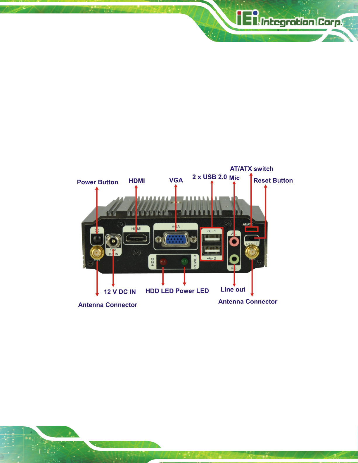
uIB X-210-CV-N2600 Embedded S ystem
1 x AT/AT X Swit ch
1 x HDD LED
1 x HDMI port
1 x Line out
1 x Mic
1 x Power button
1 x Power LED
1 x Reset button
2 x USB 2.0 connectors
1 x 12 V DC IN
1 x VGA port
Figure 1-3: uIBX-210-CV-N2600 Rear Panel
Page 7
Page 19
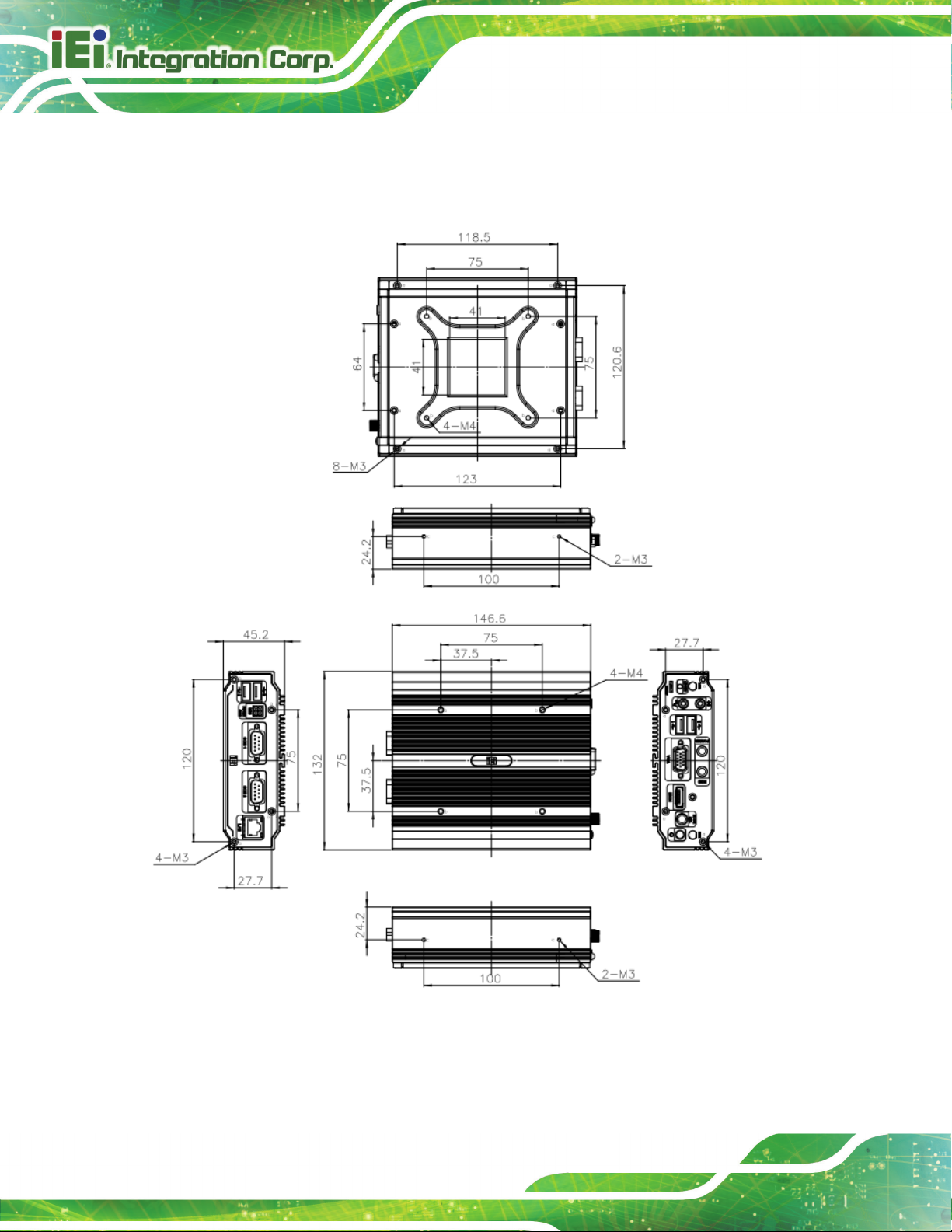
1.7 Dimens ions
The physical dimensions are shown below:
uIB X-210-CV-N2600 Embedded S ystem
Page 8
Figure 1-4: Physical Dimensions (mm)
Page 20
uIB X-210-CV-N2600 Embedded S ystem
C hapter
2
2 Unpacking
Page 9
Page 21

2.1 A nti-s tatic P rec autions
WAR NING:
Failure to take ESD precautions during installation may result in
permanent damage to the uIBX-210-CV-N2600 and severe injury to
the user.
Electrostatic discharge (ESD) can cause serious damage to electronic components,
including the uIBX-210-CV-N2600. Dry climates are especially susceptible to ESD. It is
therefore critical that whenever the uIBX-210-CV-N2600 or any other electrical component
is handled, the following anti-static precautions are strictly adhered to.
Wear an anti-static wristband: Wearing a simple anti-static wristband can
uIB X-210-CV-N2600 Embedded S ystem
help to prevent ESD from damaging the board.
Self-grounding: Before handling the board, touch any grounded conducting
material. During the time the board is handled, frequently touch any
conducting materials that are connected to the ground.
Use an anti-static pad: When configuring the uIBX-210-CV-N2600, place it
on an antic-static pad. This reduces the possibility of ESD damaging the
uIBX-210-CV-N2600.
2.2 Unpacking P recautions
When the uIBX-210-CV-N2600 is unpacked, please do the following:
Follow the anti-static precautions outlined in Section
Make sure the packing box is facing upwards so the uIBX-210-CV-N2600
does not fall out of the box.
Make sure all the components shown in Section
333H2.1.
334H2.3 are present.
Page 10
Page 22

uIB X-210-CV-N2600 Embedded S ystem
2.3 P acking L is t
NOTE :
If some of the components listed in the checklist below are missing,
please do not proceed with the installation. Contact the IEI reseller or
vendor you purchased the uIBX-210-CV-N2600 from or contact an IEI
sales representative directly. To contact an IEI sales representative,
please send an email to
The uIBX-210-CV-N2600 is shipped with the following components:
Quantity Item and Part Number Image
1 uIBX-210-CV-N2600
1 1 x Adaptor 12V/5A
1 1 x Screw set
Table 2-1: Package List Contents
165Hsales@iei.com.tw.
Page 11
 Loading...