

IEI Technology tKINO-ULT3, tKINO-ULT3-i7-R10, tKINO-ULT3-i5-R10, tKINO-ULT3-i3-R10, tKINO-ULT3-C-R10 User Manual
...Page 1

tKINO-ULT3 SBC
tKINO-ULT3 CPU Card
MODEL:
tKINO-ULT3
Thin Mini-ITX SBC with 14nm Intel® Core i7/i5/i3 or Celeron®
On-board SoC, Dual HDMI, LVDS/eDP, Dual GbE, USB 3.0, PCIe Mini,
SATA 6Gb/s, eMMC 5.0, RS-232/422/485, HD Audio, and RoHS
User Manual
Rev. 1.00 - March 30, 2017
Page I
Page 2

Date Version Changes
March 30, 2017 1.00 Initial release
tKINO-ULT3 SBC
Revision
Page II
Page 3

tKINO-ULT3 SBC
COPYRIGHT NOTICE
The information in this document is subject to change without prior notice in order to
improve reliability, design and function and does not represent a commitment on the part
of the manufacturer.
In no event will the manufacturer be liable for direct, indirect, special, incidental, or
consequential damages arising out of the use or inability to use the product or
documentation, even if advised of the possibility of such damages.
This document contains proprietary information protected by copyright. All rights are
Copyright
reserved. No part of this manual may be reproduced by any mechanical, electronic, or
other means in any form without prior written permission of the manufacturer.
TRADEMARKS
All registered trademarks and product names mentioned herein are used for identification
purposes only and may be trademarks and/or registered trademarks of their respective
owners.
Page III
Page 4

tKINO-ULT3 SBC
Manual Conventions
WARNING
Warnings appear where overlooked details may cause damage to the
equipment or result in personal injury. Warnings should be taken
seriously.
CAUTION
Cautionary messages should be heeded to help reduce the chance of
losing data or damaging the product.
NOTE
These messages inform the reader of essential but non-critical
information. These messages should be read carefully as any directions
or instructions contained therein can help avoid making mistakes.
HOT SURFACE
This symbol indicates a hot surface that should not be touched without
taking care.
Page IV
Page 5

tKINO-ULT3 SBC
Table of Contents
1 INTRODUCTION.......................................................................................................... 1
1.1 INTRODUCTION........................................................................................................... 2
1.2 MODEL VARIATIONS ................................................................................................... 3
1.3 FEATURES................................................................................................................... 3
1.4 CONNECTORS ............................................................................................................. 4
1.5 DIMENSIONS............................................................................................................... 6
1.6 DATA FLOW................................................................................................................ 8
1.7 TECHNICAL SPECIFICATIONS ...................................................................................... 9
2 UNPACKING............................................................................................................... 12
2.1 ANTI-STATIC PRECAUTIONS...................................................................................... 13
2.2 UNPACKING PRECAUTIONS....................................................................................... 13
2.3 PACKING LIST........................................................................................................... 14
2.4 OPTIONAL ITEMS...................................................................................................... 15
3 CONNECTORS ........................................................................................................... 16
3.1 PERIPHERAL INTERFACE CONNECTORS..................................................................... 17
3.1.1 tKINO-ULT3 Layout........................................................................................ 17
3.1.2 Peripheral Interface Connectors ..................................................................... 18
3.1.3 External Interface Panel Connectors............................................................... 19
INTERNAL PERIPHERAL CONNECTORS ...................................................................... 20
3.2
3.2.1 Audio Connector .............................................................................................. 20
3.2.2 Battery Connector............................................................................................ 21
3.2.3 Chassis Intrusion Connector............................................................................ 22
3.2.4 DC-IN Power Connector ................................................................................. 23
3.2.5 Digital I/O Connector...................................................................................... 24
3.2.6 eDP Connector................................................................................................. 25
3.2.7 Fan Connector, CPU........................................................................................ 27
3.2.8 Fan Connector, System..................................................................................... 28
3.2.9 Front Panel Connector.................................................................................... 29
3.2.10 I
2
C Connector ................................................................................................ 30
Page V
Page 6

tKINO-ULT3 SBC
3.2.11 LVDS Backlight Inverter Connector.............................................................. 31
3.2.12 LVDS LCD Connector ................................................................................... 32
3.2.13 LAN LED Connectors.................................................................................... 33
3.2.14 Memory Slot................................................................................................... 34
3.2.15 PCI Express x4 Slot........................................................................................ 34
3.2.16 PCIe Mini Card Slot (for mSATA Modules)................................................... 35
3.2.17 PCIe Mini Card Slot (for 3G Modules) ......................................................... 36
3.2.18 Power Button ................................................................................................. 38
3.2.19 RS-232 Serial Port Connectors...................................................................... 39
3.2.20 RS-232/422/485 Serial Port Connector......................................................... 40
3.2.21 SATA 6Gb/s Drive Connectors....................................................................... 41
3.2.22 SATA Power Connectors................................................................................ 42
3.2.23 SMBus Connector .......................................................................................... 43
3.2.24 SIM Card Slot................................................................................................. 44
3.2.25 SPI Flash Connector, BIOS............................................................................ 45
3.2.26 SPI Flash Connector, EC ............................................................................... 46
3.2.27 USB Connector .............................................................................................. 47
3.3
EXTERNAL PERIPHERAL INTERFACE CONNECTOR PANEL ......................................... 48
3.3.1 Audio Jacks ...................................................................................................... 48
3.3.2 HDMI Connector............................................................................................. 49
3.3.3 HDMI/DP Combo Connector.......................................................................... 50
3.3.4 LAN Connectors............................................................................................... 51
3.3.5 Power Connector (Power Adapter)................................................................. 52
3.3.6 USB 3.0 Connectors......................................................................................... 52
4 INSTALLATION ......................................................................................................... 53
ANTI-STATIC PRECAUTIONS...................................................................................... 54
4.1
4.2 INSTALLATION CONSIDERATIONS.............................................................................. 54
4.3 SO-DIMM INSTALLATION ....................................................................................... 56
4.4 PCIE MINI CARD INSTALLATION .............................................................................. 56
4.5 SIM CARD INSTALLATION........................................................................................ 58
4.6 SYSTEM CONFIGURATION......................................................................................... 60
4.6.1 AT/ATX Mode Select Switch............................................................................. 60
4.6.2 Clear CMOS Button......................................................................................... 61
4.6.3 Flash Descriptor Security Override Jumper.................................................... 61
Page VI
Page 7

tKINO-ULT3 SBC
4.6.4 HDMI/DP Select Switch................................................................................... 63
4.6.5 LVDS/eDP Select Switch.................................................................................. 64
4.6.6 LVDS Panel Resolution Select Switch ............................................................. 65
4.6.7 LVDS Voltage Select Switch............................................................................. 66
4.6.8 USB Power Select............................................................................................ 67
4.7 CHASSIS INSTALLATION............................................................................................ 68
4.7.1 Airflow.............................................................................................................. 68
4.7.2 Motherboard Installation................................................................................. 68
4.8 INTERNAL PERIPHERAL DEVICE CONNECTIONS........................................................ 68
4.8.1 RS-232 Cable Connection................................................................................ 68
4.8.2 SATA Drive Connection ................................................................................... 69
4.9
INTEL® AMT SETUP PROCEDURE............................................................................. 71
5 BIOS.............................................................................................................................. 72
5.1 INTRODUCTION......................................................................................................... 73
5.1.1 Starting Setup................................................................................................... 73
5.1.2 Using Setup...................................................................................................... 73
5.1.3 Getting Help..................................................................................................... 74
5.1.4 Unable to Reboot after Configuration Changes.............................................. 74
5.1.5 BIOS Menu Bar................................................................................................ 74
5.2 MAIN........................................................................................................................ 75
5.3 ADVANCED............................................................................................................... 76
5.3.1 ACPI Settings................................................................................................... 77
5.3.2 AMT Configuration.......................................................................................... 78
5.3.3 Super IO Configuration
................................................................................... 79
5.3.3.1 Serial Port n Configuration....................................................................... 80
5.3.3.1.1 Serial Port 1 Configuration................................................................ 80
5.3.3.1.2 Serial Port 2 Configuration................................................................ 81
5.3.3.1.3 Serial Port 3 Configuration................................................................ 82
5.3.3.1.4 Serial Port 4 Configuration................................................................ 83
5.3.3.1.5 Serial Port 5 Configuration................................................................ 84
5.3.3.1.6 Serial Port 6 Configuration................................................................ 85
5.3.4 iWDD H/W Monitor......................................................................................... 86
5.3.4.1 Smart Fan Mode Configuration................................................................ 87
5.3.5 RTC Wake Settings........................................................................................... 90
Page VII
Page 8

tKINO-ULT3 SBC
5.3.6 Serial Port Console Redirection...................................................................... 91
5.3.6.1 Legacy Console Redirection Settings....................................................... 92
5.3.6.2 Console Redirection Settings.................................................................... 93
5.3.7 CPU Configuration.......................................................................................... 95
5.3.8 SATA Configuration ......................................................................................... 97
5.3.9 USB Configuration........................................................................................... 99
5.3.10 IEI Feature................................................................................................... 100
5.4 CHIPSET ................................................................................................................. 101
5.4.1 System Agent (SA) Configuration .................................................................. 101
5.4.1.1 Graphics Configuration........................................................................... 102
5.4.1.1.1 LCD Control .................................................................................... 104
5.4.1.2 Memory Configuration ........................................................................... 105
5.4.2 PCH-IO Configuration .................................................................................. 106
5.4.2.1 PCI Express Configuration..................................................................... 107
5.4.2.2 HD Audio Configuration......................................................................... 108
5.5
SECURITY............................................................................................................... 109
5.6 BOOT.......................................................................................................................110
5.7 EXIT........................................................................................................................112
6 SOFTWARE DRIVERS.............................................................................................114
6.1 SOFTWARE INSTALLATION .......................................................................................115
6.2 AVAILABLE SOFTWARE DRIVERS .............................................................................116
6.3 INSTALLING WINDOWS 7 FROM USB 3.0 DRIVES....................................................117
A REGULATORY COMPLIANCE.............................................................................118
B PRODUCT DISPOSAL............................................................................................ 120
C BIOS MENU OPTIONS........................................................................................... 122
D TERMINOLOGY ..................................................................................................... 126
E DIGITAL I/O INTERFACE..................................................................................... 129
F WATCHDOG TIMER............................................................................................... 132
G HAZARDOUS MATERIALS DISCLOSURE....................................................... 135
Page VIII
Page 9

tKINO-ULT3 SBC
List of Figures
Figure 1-1: tKINO-ULT3..................................................................................................................2
Figure 1-2: Connectors (Front Side).............................................................................................4
Figure 1-3: Connectors (Solder Side)...........................................................................................5
Figure 1-4: Dimensions with Standard Heatsink (mm)...............................................................6
Figure 1-5: Dimensions with Optional Heatsink (mm)................................................................7
Figure 1-6: Data Flow Diagram......................................................................................................8
Figure 3-1: Connector and Jumper Locations...........................................................................17
Figure 3-2: Audio Connector Location.......................................................................................20
Figure 3-3: Battery Connector Location.....................................................................................21
Figure 3-4: Chassis Intrusion Connector Location...................................................................22
Figure 3-5: DC-IN Power Connector Location ...........................................................................23
Figure 3-6: Digital I/O Connector Location ................................................................................24
Figure 3-7: eDP Connector Location..........................................................................................25
Figure 3-8: CPU Fan Connector Location..................................................................................27
Figure 3-9: System Fan Connector Location.............................................................................28
Figure 3-10: Front Panel Connector Location ...........................................................................29
Figure 3-11: I2C Connector Location ..........................................................................................30
Figure 3-12: Backlight Inverter Connector Location.................................................................31
Figure 3-13: LVDS Connector Location......................................................................................32
Figure 3-14: LAN LED Connector Locations .............................................................................33
Figure 3-15: Memory Slot Locations...........................................................................................34
Figure 3-16: PCIe x4 Slot Location .............................................................................................34
Figure 3-17: Full-size PCIe Mini Card Slot Location .................................................................35
Figure 3-18: Half-size PCIe Mini Slot Location..........................................................................37
Figure 3-19: Power Button Location...........................................................................................38
Figure 3-20: RS-232 Serial Port Connector Locations..............................................................39
Figure 3-21: RS-232/422/485 Connector Location.....................................................................40
Figure 3-22: SATA 6Gb/s Drive Connectors Locations............................................................41
Figure 3-23: SATA Power Connector Locations .......................................................................42
Figure 3-24: SMBus Connector Location...................................................................................43
Figure 3-25: SIM Card Slot Location...........................................................................................44
Page IX
Page 10

Figure 3-26: SPI Flash Connector Location...............................................................................45
Figure 3-27: SPI Flash Connector Location...............................................................................46
Figure 3-28: USB Connector Location........................................................................................47
Figure 3-29: External Peripheral Interface Connector..............................................................48
Figure 3-30: HDMI Connector Pinout Locations........................................................................49
Figure 3-31: HDMI/DP Combo Connector Pinout Locations....................................................51
Figure 3-32: LAN Connector........................................................................................................51
Figure 3-33: Power Jack ..............................................................................................................52
Figure 4-1: SO-DIMM Installation................................................................................................56
Figure 4-2: Removing the Retention Screw...............................................................................57
Figure 4-3: Inserting the Full-size PCIe Mini Card into the Slot at an Angle..........................57
Figure 4-4: Securing the Full-size PCIe Mini Card ....................................................................58
Figure 4-5: Unlock SIM Card Slot Cover ....................................................................................58
Figure 4-6: SIM Card Installation.................................................................................................59
tKINO-ULT3 SBC
Figure 4-7: Lock SIM Card Slot Cover........................................................................................59
Figure 4-8: AT/ATX Mode Select Switch Location ....................................................................60
Figure 4-9: Clear CMOS Button Location...................................................................................61
Figure 4-10: Flash Descriptor Security Override Jumper Location ........................................62
Figure 4-11: HDMI/DP Select Switch Location...........................................................................63
Figure 4-12: LVDS/eDP Select Switch Location........................................................................64
Figure 4-13: LVDS Panel Resolution Select Switch Location..................................................66
Figure 4-14: LVDS Voltage Select Switch Location..................................................................67
Figure 4-15: Single RS-232 Cable Installation ...........................................................................69
Figure 4-16: SATA Drive Cable Connection...............................................................................70
Page X
Page 11

tKINO-ULT3 SBC
List of Tables
Table 1-1: tKINO-ULT3 Model Variations......................................................................................3
Table 1-2: Technical Specifications............................................................................................11
Table 3-1: Peripheral Interface Connectors...............................................................................19
Table 3-2: Rear Panel Connectors..............................................................................................19
Table 3-3: Audio Connector Pinouts ..........................................................................................20
Table 3-4: Battery Connector Pinouts........................................................................................21
Table 3-5: Chassis Intrusion Connector Pinouts......................................................................22
Table 3-6: DC-IN Power Connector Pinouts...............................................................................23
Table 3-7: Digital I/O Connector Pinouts....................................................................................24
Table 3-8: eDP Connector Pinouts..............................................................................................26
Table 3-9: CPU Fan Connector Pinouts......................................................................................27
Table 3-10: System Fan Connector Pinouts..............................................................................28
Table 3-11: Front Panel Connector Pinouts...............................................................................29
Table 3-12: I2C Connector Pinouts..............................................................................................30
Table 3-13: Backlight Inverter Connector Pinouts....................................................................31
Table 3-14: LVDS Connector Pinouts.........................................................................................33
Table 3-15: LAN LED Connector Pinouts...................................................................................33
Table 3-16: PCIe Mini Slot Pinouts (for mSATA Modules)........................................................36
Table 3-17: PCIe Mini Card Slot Pinouts (for 3G Modules).......................................................38
Table 3-18: RS-232 Serial Port Connector Pinouts...................................................................39
Table 3-19: RS-232/422/485 Connector Pinouts........................................................................40
Table 3-20: DB-9 RS-232/422/485 Pinouts..................................................................................41
Table 3-21: SATA Power Connector Pinouts.............................................................................42
Table 3-22: SMBus Connector Pinouts ......................................................................................43
Table 3-23: SPI Flash Connector Pinouts ..................................................................................45
Table 3-24: SPI Flash Connector Pinouts ..................................................................................46
Table 3-25: USB Connector Pinouts...........................................................................................47
Table 3-26: HDMI Connector Pinouts .........................................................................................49
Table 3-27: HDMI/DP Combo Connector Pinouts......................................................................50
Table 3-28: LAN Pinouts ..............................................................................................................51
Table 3-29: USB 3.0 Port Pinouts................................................................................................52
Page XI
Page 12

Table 4-1: AT/ATX Mode Select Switch Settings.......................................................................60
Table 4-2: Flash Descriptor Security Override Jumper Settings.............................................62
Table 4-3: HDMI/DP Select Switch Settings...............................................................................63
Table 4-4: LVDS/eDP Select Switch Settings.............................................................................64
Table 4-5: LVDS Panel Resolution Selection.............................................................................65
Table 4-6: LVDS Voltage Select Switch Settings.......................................................................66
Table 4-4: USB Power Selection BIOS Options.........................................................................67
tKINO-ULT3 SBC
Page XII
Page 13
tKINO-ULT3 SBC
List of BIOS Menus
BIOS Menu 1: Main.......................................................................................................................75
BIOS Menu 2: Advanced..............................................................................................................76
BIOS Menu 3: ACPI Settings .......................................................................................................77
BIOS Menu 4: AMT Configuration...............................................................................................78
BIOS Menu 5: Super IO Configuration........................................................................................79
BIOS Menu 6: Serial Port n Configuration .................................................................................80
BIOS Menu 7: iWDD H/W Monitor ...............................................................................................86
BIOS Menu 8: Smart Fan Mode Configuration ..........................................................................87
BIOS Menu 9: RTC Wake Settings..............................................................................................90
BIOS Menu 10: Serial Port Console Redirection.......................................................................91
BIOS Menu 11: Legacy Console Redirection Settings .............................................................92
BIOS Menu 12: Console Redirection Settings...........................................................................93
BIOS Menu 13: CPU Configuration.............................................................................................95
BIOS Menu 14: SATA Configuration...........................................................................................97
BIOS Menu 15: USB Configuration.............................................................................................99
BIOS Menu 16: IEI Feature........................................................................................................ 100
BIOS Menu 17: Chipset............................................................................................................. 101
BIOS Menu 18: System Agent (SA) Configuration................................................................. 101
BIOS Menu 19: Graphics Configuration.................................................................................. 102
BIOS Menu 20: LCD Control..................................................................................................... 104
BIOS Menu 21: Memory Configuration.................................................................................... 105
BIOS Menu 22: PCH-IO Configuration..................................................................................... 106
BIOS Menu 23: PCI Express Configuration ............................................................................ 107
BIOS Menu 24: HD Audio Configuration................................................................................. 108
BIOS Menu 25: Security............................................................................................................ 109
BIOS Menu 26: Boot.................................................................................................................. 110
BIOS Menu 27: Exit.................................................................................................................... 112
Page XIII
Page 14

Page 15

tKINO-ULT3 SBC
Chapter
1
1 Introduction
Page 1
Page 16

1.1 Introduction
tKINO-ULT3 SBC
Figure 1-1: tKINO-ULT3
The tKINO-ULT3 series is a Mini-ITX form factor single bard computer. It has an on-board
®
14nm Intel
dual-channel DDR4 SDRAM SO-DIMM slots with up to 32.0 GB of memory.
The tKINO-ULT3 series includes an internal LVDS/eDP connector, one HDMI connector
and one HDMI/DP combo connector for triple independent display.
Expansion and I/O include two full-size PCIe Mini slots supporting mSATA and 3G
modules, four USB 3.0 connectors on the rear panel, four USB 2.0 connectors by pin
header and two SATA 6Gb/s connectors. Serial device connectivity is provided by four
internal RS-232 connectors and two internal RS-232/ 422/485 connectors. T wo RJ-45 GbE
connectors provide the system with smooth connections to an external LAN. One
on-board SIM card socket also supports for 3G/LTE expansion.
Core™ i7/i5/i3 or Celeron® processor, and supports two 260-pin 2133 MHz
Page 2
Page 17

tKINO-ULT3 SBC
1.2 Model Variations
The model variations of the tKINO-ULT3 series are listed below.
Model No. SoC
tKINO-ULT3-i7-R10
tKINO-ULT3-i5-R10
tKINO-ULT3-i3-R10
tKINO-ULT3-C-R10
tKINO-ULT3-CE-R10
®
Intel
Core™ i7-6600U on-board SoC
(up to 3.4 GHz, dual-core, 4 MB cache, TDP=15 W)
®
Intel
Core™ i5-6300U on-board SoC
(up to 3.0 GHz, dual-core, 3 MB cache, TDP=15 W)
®
Intel
Core™ i3-6100U on-board SoC
(up to 2.3 GHz, dual-core, 3 MB cache, TDP=15 W)
®
Intel
Celeron® 3955U on-board SoC
(up to 2.0 GHz, dual-core, 2 MB cache, TDP=15 W)
®
Intel
Celeron® 3855U on-board SoC
(up to 1.6 GHz, dual-core, 2 MB cache, TDP=15 W)
Table 1-1: tKINO-ULT3 Model Variations
1.3 Features
Some of the tKINO-ULT3 motherboard features are listed below:
Thin Mini-ITX motherboard with 6
Triple independent display
Two 2133 MHz DDR4 SO-DIMM slots support up to 32 GB of memory
Easy assembly heatsink module (with or without fan) for thermal management
One full-size PCIe Mini card slot with SIM card socket for 3G/LTE expansion
One full-size PCIe Mini card slot supports mSATA modules
Two SATA 6Gb/s connectors with power output
Four USB 3.0 external connectors
Four RS-232 connectors and two RS-232/422/485 conne ctors
Optional eMMC 5.0 up to 32 GB
th
generation Intel® ULT processor
IEI One Key Recovery solution allows you to create rapid OS backup and
recovery
Page 3
Page 18

1.4 Connectors
The connectors on the tKINO-ULT3 are shown in the figure below.
tKINO-ULT3 SBC
Figure 1-2: Connectors (Front Side)
Page 4
Page 19

tKINO-ULT3 SBC
Figure 1-3: Connectors (Solder Side)
Page 5
Page 20

1.5 Dimensions
Figure 1-4 shows the dimensions of the tKINO-ULT3 installed with the standard heatsink
(with fan).
tKINO-ULT3 SBC
Page 6
Figure 1-4: Dimensions with Standard Heatsink (mm)
Page 21

tKINO-ULT3 SBC
Figure 1-5 shows the dimensions of the tKINO-ULT3 installed with the optional heatsink
(without fan, P/N: 34000-000645-RS).
Figure 1-5: Dimensions with Optional Heatsink (mm)
Page 7
Page 22

1.6 Data Flow
Figure 1-6 shows the data flow between the system chipset, the CPU and other
components installed on the motherboard.
tKINO-ULT3 SBC
Page 8
Figure 1-6: Data Flow Diagram
Page 23

tKINO-ULT3 SBC
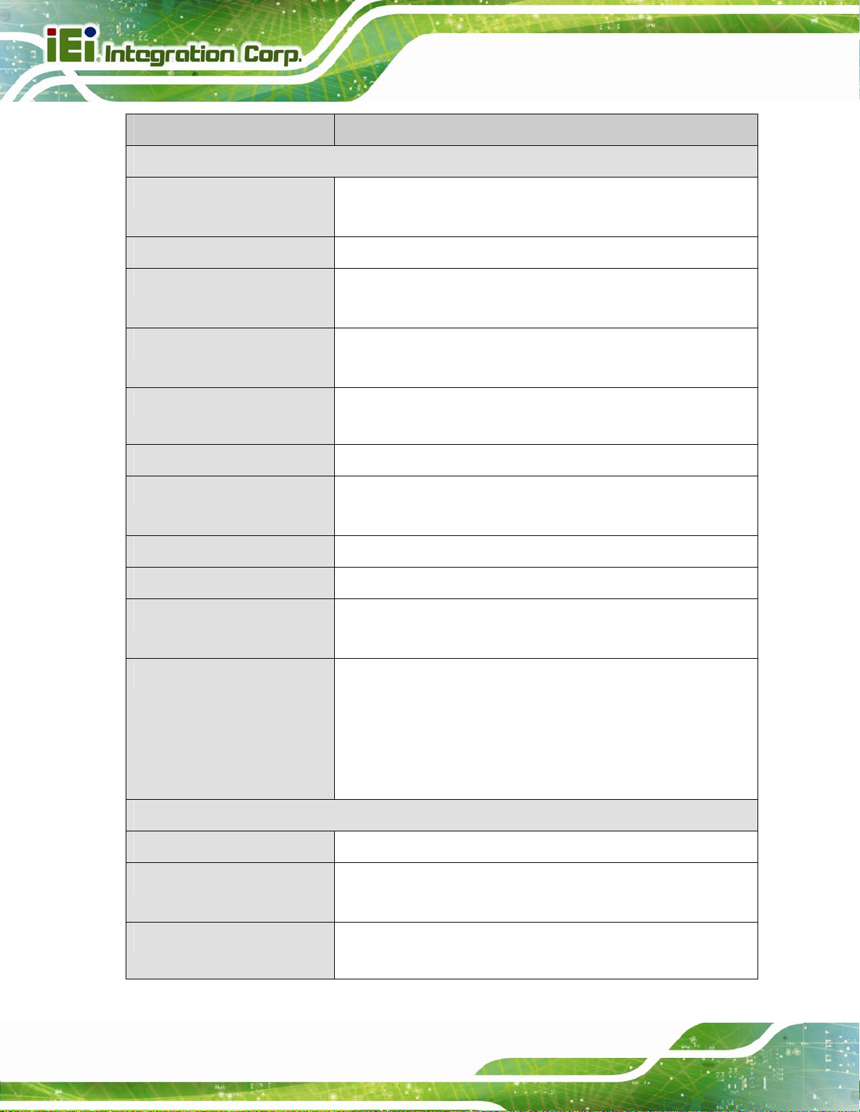
1.7 Technical Specifications
tKINO-ULT3 technical specifications are listed below.
Specification tKINO-ULT3
SoC
BIOS
Memory
Graphics
Display Output
6th generation Intel® mobile ULT on-board SoC:
Intel® Core i7-6600U on-board SoC
(up to 3.4 GHz, dual-core, 4 MB cache, TDP=15 W)
Intel® Core i5-6300U on-board SoC
(up to 3.0 GHz, dual-core, 3 MB cache, TDP=15 W)
Intel® Core i3-6100U on-board SoC
(up to 2.3 GHz, dual-core, 3 MB cache, TDP=15 W)
Intel® Celeron® 3955U on-board SoC
(up to 2.0 GHz, dual-core, 2 MB cache, TDP=15 W)
Intel® Celeron® 3855U on-board SoC
(up to 1.6 GHz, dual-core, 2 MB cache, TDP=15 W)
AMI UEFI BIOS
Two 260-pin 2133 MHz dual-channel DDR4 SO-DIMM slots
(system max. 32 GB)
9th generation Intel® HD Graphics
Triple independent display
Ethernet
Digital I/O
Super IO
Embedded Controller
Audio
Watchdog Timer
1 x HDMI 2.4 (up to 4096x2160 @ 24 Hz)
1 x HDMI/DP (up to 4096x2160 @ 24 Hz)
1 x LVDS/eDP (selected by switch)
LAN1: Intel® I219-LM PHY with Intel® AMT 11.0 support
LAN2: Intel® I211-AT PCIe GbE controller with NCSI support
8-bit digital I/O by 10-pin (2x5) header
Fintek F81866D-I
ITE IT8528E/FX
Realtek ALC662 HD codec
Software programmable support 1~255 sec. system reset
Page 9
Page 24
Specification tKINO-ULT3
I/O Interface
tKINO-ULT3 SBC
Audio Connector
Ethernet
Serial Ports
USB Ports
Front Panel
LAN LED
Fan
SMBus
I2C
2 x Audio jack (line-out, mic-in) on rear I/O
1 x Analog audio by 10-pin (2x5) header
2 x RJ-45 GbE port
2 x RS-232/422/485 by 10-pin (2x5) header
4 x RS-232 by 10-pin (2x5) header
4 x USB 3.0 on rear I/O
4 x USB 2.0 by 8-pin (2x4) header
1 x Front panel connector by 14-pin (2x7) header (for connecting
power LED, HDD LED, power button and reset button)
2 x LAN link LED connector by 2-pin header
1 x CPU fan connector by 4-pin (1x4) wafer
1 x System fan connector by 3-pin (1x3) wafer
1 x SMBus connector by 4-pin (1x4) wafer
1 x I2C connector by 4-pin (1x4) wafer
Storage
Expansion
Environmental and Power Specifications
Power Supply
Power Connector
Power Consumption
2 x SATA 6Gb/s with 5 V SATA power co nnectors
Optional eMMC 5.0 (up to 32 GB)
1 x PCIe x4 slot
1 x Full-size PCIe Mini card slot (support mSATA, colay SATA2)
1 x Full-size PCIe Mini card slot (with SIM card socket)
*3855U CPU belongs to Skylake ULT Base series which supports
PCIe Gen 2 signal only.
9 V ~ 36 V DC input (AT/ATX power mode)
1 x Internal power connector by 4-pin (2x2) connector
1 x External DC power jack (Ø5.5mm)
12 V @ 4.68 A (Intel® Core™ i7-6600U up to 3.4 GHz CPU with
16 GB (two 8 GB) DDR4 2133 MHz memory running in 3.2 GHz)
Page 10
Page 25

tKINO-ULT3 SBC
Specification tKINO-ULT3
Operating Temperature
Storage Temperature
Humidity
Physical Specifications
Dimensions
Weight GW/NW
Table 1-2: Technical Specifications
-20°C ~ 60°C
-30°C ~ 70°C
5% ~ 95%, non-condensing
170 mm x 170 mm
900 g / 375 g
Page 11
Page 26

tKINO-ULT3 SBC
Chapter
2
2 Unpacking
Page 12
Page 27

tKINO-ULT3 SBC
2.1 Anti-static Precautions
WARNING!
Static electricity can destroy certain electronics. Make sure to follow the
ESD precautions to prevent damage to the product, and injury to the
user.
Make sure to adhere to the following guidelines:
Wear an anti-static wristband: Wearing an anti-static wristband can prevent
electrostatic discharge.
Self-grounding: Touch a grounded conductor every few minutes to discharge
any excess static buildup.
Use an anti-static pad: When configuring any circuit board, place it on an
anti-static mat.
Only handle the edges of the PCB: Don't touch the surface of the
motherboard. Hold the motherboard by the edges when handling.
2.2 Unpacking Precautions
When the tKINO-ULT3 is unpacked, please do the following:
Follow the antistatic guidelines above.
Make sure the packing box is facing upwards whe n opening.
Make sure all the packing list items are present.
Page 13
Page 28

2.3 Packing List
NOTE:
If any of the components listed in the checklist below are missing, do not
proceed with the installation. Contact the IEI reseller or vendor the
tKINO-ULT3 was purchased from or contact an IEI sales representative
tKINO-ULT3 SBC
directly by sending an email to sales@ieiworld.com
The tKINO-ULT3 is shipped with the following components:
Quantity Item and Part Number Image
1 tKINO-ULT3 single board computer
2 SATA with power cable kit
1 I/O shielding
.
Page 14
1 Utility CD
1 One Key Recovery CD
 Loading...