

IEI Technology TANK-860-HM86i-i5/4G/4A-R10, TANK-860-HM86i-i5/4G/2A-R10, TANK-860-HM86i-C/4G/4A-R10, TANK-860-HM86i-C/4G/6A-R10, TANK-860-HM86i-i5/4G/6A-R10 User Manual
...Page 1

TANK-860-HM86 Embedded S ystem
Page i
MODEL:
HM86 Series
RoHS Compliant
Rev. 1.04 – 29 April 2015
TANK-860-
Embedded System with 4th Generation Intel® Core™ proces sor,
VGA, DVI-I, Display Port, Tw o Gigabit Eth ern et,
Four USB 3.0, Tw o USB 2.0, R S-232/422/485,
User Manual
Page 2

TANK-860-HM86 Embedded S ystem
Page ii
Revision
Date Version Changes
29 April 2015 1.04 Update Section 1.4: Technical Specificatio ns
( Change Operating Temperature to -20°C ~ 60°C)
26 March 2015 1.03 Update P.N of system fan
Add connector pinouts of backplane
12 March 2015 1.02 Update P.N of Power Adapter (150W)
19 December 2014 1.01 Update Section 1.8: Backplane Options
14 November 2014 1.00 Initial release
Page 3

TANK-860-HM86 Embedded S ystem
Page iii
Copyright
COP YRIGHT NOTICE
The information in this document is subject to change without prior notice in order to
improve reliabilit y, design a nd functi on and d oes not r epresent a com mitm ent on the part
of the manufacturer.
In no event will the manufacturer be liable for direct, indirect, special, incidental, or
consequential damages arising out of the use or inability to use the product or
documentation, even if advised of the possibility of such damages.
This document contains proprietary information protected by copyright. All rights are
reserved. No part of this manual may be reproduced by any mechanical, e lectronic, or
other means in any form without prior written permission of the manufacturer.
TRADEMARKS
All registered tradem ark s and produc t nam es ment ioned here in are us ed for identif icatio n
purposes only and m ay be trademarks and/or registe red trademarks of their respec tive
owners.
Page 4

TANK-860-HM86 Embedded S ystem
Page iv
Ta b le of Con te nts
1 INTRODUCTION ........................................................................................................... 1
1.1 OVERVIEW ................................................................................................................... 2
1.2 MODEL VARIATIONS ..................................................................................................... 3
1.3 FEATURES ................................................................................................................... 3
1.4 TECHNICAL SPECIFICATIONS ........................................................................................ 4
1.5 FRONT PANEL .............................................................................................................. 6
1.5.1 T ANK-860-HM86-2 slot Front Panel ................................................................. 6
1.5.2 T ANK-860-HM86-4 slot Front Panel ................................................................. 8
1.5.3 T ANK-860-HM86-6 slot Front Panel ............................................................... 10
1.6 REAR PANEL ............................................................................................................... 11
1.7 LED INDICATORS ...................................................................................................... 12
1.8 BACKPLANE OPTIONS ................................................................................................ 14
1.9 PHYSICAL DIMENSIONS .............................................................................................. 23
1.9.1 T ANK-860-HM86 Physical Dimensions (2-slot) .............................................. 23
1.9.2 T ANK-860-HM86 Physical Dimensions (4-slot) .............................................. 24
1.9.3 T ANK-860-HM86 Physical Dimensions (6-slot) .............................................. 25
2 UNPACKING ................................................................................................................ 26
2.1 ANTI-STATIC PRECAUTIONS ........................................................................................ 27
2.2 UNPACKING PRECAUTIONS ........................................................................................ 27
2.3 UNPACKING CHECKLIST ............................................................................................. 28
3 INSTALLATION ........................................................................................................... 31
3.1 INSTALLATION PRECAUTIONS ..................................................................................... 32
3.2 CFAST INSTALLATION ................................................................................................. 32
3.3 HARD DISK DRIVE (HDD) INSTALLATION ................................................................... 33
3.4 SYSTEM FAN INSTALLATION ......................................................................................... 36
3.5 MOUNTING THE SYSTEM WITH MOUNTING BRACKETS ................................................. 37
3.6 EXTERNAL PERIPHERAL INTERFACE CONNECTORS ...................................................... 37
3.6.1 ACC Mode Selection ........................................................................................ 38
3.6.2 AT/ATX Power Mode Selection ........................................................................ 39
Page 5

TANK-860-HM86 Embedded S ystem
Page v
3.6.3 Audio Connector .............................................................................................. 39
3.6.4 CFast Socket .................................................................................................... 40
3.6.5 Digital Input/Output Connector ....................................................................... 40
3.6.6 DVI Connector ................................................................................................. 40
3.6.7 LAN Connectors ............................................................................................... 41
3.6.8 Power Input, 3-pin Terminal Block .................................................................. 43
3.6.9 Power Input, 4-pin DIN Connector ................................................................. 43
3.6.10 RJ-45 RS-232 Serial Ports ............................................................................. 43
3.6.11 DB-9 RS-232/422/485 Serial Port Connectors .............................................. 44
3.6.12 USB Connectors ............................................................................................. 45
3.6.13 VGA Connector .............................................................................................. 46
3.7 POWERING ON/OFF THE SYSTEM ............................................................................... 47
3.8 POWER ...................................................................................................................... 48
3.8.1 ACC ON Mode ................................................................................................. 49
3.8.2 ACC OFF Mode ............................................................................................... 50
4 SYSTEM MOTHERBOARD ........................................................................................ 51
4.1 OVERVIEW ................................................................................................................. 52
4.1.1 Layout .............................................................................................................. 52
4.2 INTERNAL PERIPHERAL CONNECTORS ......................................................................... 53
4.2.1 Backplane +12V Power Connector (BP_PWR1) ............................................. 53
4.2.2 Battery Connector (BAT1) ............................................................................... 54
4.2.3 BIOS Programming Connector (SPI1) ............................................................ 54
4.2.4 CFast Card connector (CFAST1) .................................................................... 54
4.2.5 CPU Fan Connector (CPU_FAN1) .................................................................. 54
4.2.6 EC Debug Connector (LPT_DB1) ................................................................... 55
4.2.7 EC Programming Connector (JSPI1) .............................................................. 55
4.2.8 LED Connector (J2) ......................................................................................... 55
4.2.9 SATA 3Gb/s Drive Connectors (SATA2) .......................................................... 56
4.2.10 SATA Power Connectors (CN2, CN3) ............................................................ 56
4.2.1 1 TPM Connector (TPM1) ................................................................................ 56
4.3 EXTERNAL INTERFACE PANEL CONNECTORS ................................................................ 57
4.3.1 Audio Jack (JAUDIO1) .................................................................................... 57
4.3.2 DIO connector (DIO1) ..................................................................................... 58
4.3.3 DisplayPort connector (DISPLAY_PORT1) .................................................... 58
Page 6

TANK-860-HM86 Embedded S ystem
Page vi
4.3.4 DVI Connector (DVI_1) ................................................................................... 58
4.3.5 Ethernet and USB3.0 Connectors (LAN1_USB1) ............................................ 59
4.3.6 Ethernet and USB3.0 Connectors (LAN2_USB2) ............................................ 59
4.3.7 Power Connector (PWR1) ............................................................................... 60
4.3.8 Power Connector (PWR2) ............................................................................... 60
4.3.9 RS-232 Serial Port Connector (COM1_2) ....................................................... 61
4.3.10 RS-232/422/485 Serial Port Connector (COM3_4) ...................................... 61
4.3.11 RS-232 Serial Port Connectors (LANCOM1) ................................................ 61
4.3.12 USB 2.0 Connectors (USB1) .......................................................................... 62
4.3.13 VGA Connector (VGA1) ................................................................................. 62
5 BIOS .............................................................................................................................. 63
5.1 INTRODUCTION ......................................................................................................... 64
5.1.1 Starting Setup ................................................................................................... 64
5.1.2 Using Setup ...................................................................................................... 64
5.1.3 Getting Help ..................................................................................................... 65
5.1.4 Unable to Reboot after Configuration Changes .............................................. 65
5.1.5 BIOS Menu Bar ................................................................................................ 65
5.2 MAIN ........................................................................................................................ 67
5.3 ADVANCED ................................................................................................................ 68
5.3.1 ACPI Settings ................................................................................................... 69
5.3.2 RTC Wake Settings ........................................................................................... 70
5.3.3 T rusted Computing ........................................................................................... 71
5.3.4 CPU Configuration .......................................................................................... 72
5.3.5 SATA Configuration ......................................................................................... 76
5.3.6 Intel(R) Rapid Start Technology ....................................................................... 76
5.3.7 USB Configuration ........................................................................................... 78
5.3.8 F81866 Super IO Configuration ...................................................................... 79
5.3.8.1 Serial Port n Configuration ...................................................................... 80
5.3.9 F81866 H/W Monitor ....................................................................................... 85
5.3.9.1 Smart Fan Mode Configuration ................................................................ 85
5.3.10 Serial Port Console Redirection .................................................................... 88
5.3.10.1 Console Redirection Settings .................................................................. 90
5.3.11 iEi Feature ...................................................................................................... 92
5.4 CHIPSET .................................................................................................................... 93
Page 7

TANK-860-HM86 Embedded S ystem
Page vii
5.4.1 PCH-IO Configuration .................................................................................... 94
5.4.1.1 PCI Express Configuration ....................................................................... 95
5.4.1.2 PCH Azalia Configuration ........................................................................ 96
5.4.2 System Agent (SA) Configuration .................................................................... 96
5.4.2.1 Graphics Configuration ............................................................................ 97
5.4.2.2 NB PCIe Configuration ............................................................................. 99
5.4.2.3 Memory Configuration ............................................................................ 100
5.5 BOOT ...................................................................................................................... 101
5.6 SECURITY ................................................................................................................ 102
5.7 EXIT ........................................................................................................................ 104
A REGULATORY COMPLIANCE ................................................................................ 106
B SAFETY PRECAUTIONS .......................................................................................... 111
B.1 SAFETY PRECAUTIONS .............................................................................................. 112
B.1.1 General Safety Precautions ............................................................................ 112
B.1.2 Anti-static Precautions ................................................................................... 113
B.1.3 Product Disposal ............................................................................................ 114
B.2 MAINTENANCE AND CLEANING PRECAUTIONS ........................................................... 114
B.2.1 Maintenance and Cleaning ............................................................................. 114
B.2.2 Cleaning T ools ................................................................................................ 115
C DIGITAL I/O INTERFACE ........................................................................................ 116
C.1 INTRODUCTION ........................................................................................................ 117
C.2 ASSEMBLY LANGUAGE SAMPLE 1 .............................................................................. 118
C.3 ASSEMBLY LANGUAGE SAMPLE 2 .............................................................................. 118
D HAZARDOUS MATERIALS DISCLOSURE ........................................................... 119
D.1 HAZARDOUS MATERIALS DISCLOSURE TABLE FOR IPB PRODUCTS CERTIFIED AS ROHS
COMPLIANT UNDER 2002/95/EC WITHOUT MERCURY ................................................... 120
Page 8

TANK-860-HM86 Embedded S ystem
Page viii
List of Figures
Figure 1-1: TANK-860-HM86 Series .............................................................................................. 2
Figure 1-2: TANK-860-HM86 Series Front Panel
Figure 1-3: TANK-860-HM86 Series Front Panel
Figure 1-4: TANK-860-HM86 Series Front Panel
Figure 1-5: TANK-860-HM86 Series Rear Panel
Figure 1-6: TANK-860-HM86 Series LED Indicators
Figure 1-7: HPE-2S86 (for 2-slot model)
Figure 1-8: HPE-4S86 (for 4-slot model)
Figure 1-9: HPE-6S86 (for 6-slot model)
Figure 1-10: Backplane Power
Figure 1-11: 2-slot TANK-860-HM86 Physical Dimensions (millimeters)
Figure 1-12: 4-slot TANK-860-HM86 Physical Dimensions (millimeters)
Figure 1-13: 6-slot TANK-860-HM86 Physical Dimensions (millimeters)
Figure 3-1: CFast Socket
Figure 3-2: CFast Socket Cover
Figure 3-3: Unscrew the Cover
Figure 3-4: Remove the Cover from TANK-860-HM86 Series
Figure 3-5: HDD Installation
......................................................................... 6
......................................................................... 8
.......................................................................10
.........................................................................11
..................................................................12
.....................................................................................14
.....................................................................................14
.....................................................................................17
....................................................................................................22
................................23
................................24
................................25
.............................................................................................................33
..................................................................................................33
....................................................................................................34
..................................................34
........................................................................................................35
Figure 3-6: HDD Retention Screws
Figure 3-7: System Fan Installation
Figure 3-8: Mounting Bracket Retention Screws
Figure 3-9: ACC Mode Switch
Figure 3-10: AT/ATX Power Mode Switch
Figure 3-11: Audio Connector
Figure 3-12: DIO Connector
Figure 3-13: DVI Connector
Figure 3-14: LAN Connection
Figure 3-15: RJ-45 Ethernet Connector
Figure 3-16: 3-pin Terminal Block
Figure 3-17: Power Input Connector
.............................................................................................35
............................................................................................36
......................................................................37
.....................................................................................................38
..................................................................................39
.....................................................................................................39
.........................................................................................................40
.........................................................................................................41
......................................................................................................42
......................................................................................42
...............................................................................................43
...........................................................................................43
Page 9

TANK-860-HM86 Embedded S ystem
Page ix
Figure 3-18: RJ-45 RS-232 Serial Device Connection ...............................................................44
Figure 3-19: RJ-45 RS-232 Serial Port Connector
Figure 3-20: Serial Device Connector
Figure 3-21: DB-9 RS-232/422/485 Serial Port Connector
Figure 3-22: USB Device Connection
Figure 3-23: VGA Connector
Figure 3-24: VGA Connector
Figure 3-25: Power Button
Figure 3-26: Power Connectors
Figure 4-1: System Motherboard (Front)
Figure 4-2: System Motherboard (Rear)
.....................................................................44
.........................................................................................45
........................................................45
.........................................................................................46
.......................................................................................................47
.......................................................................................................47
...........................................................................................................48
..................................................................................................49
....................................................................................52
.....................................................................................52
Page 10

TANK-860-HM86 Embedded S ystem
Page x
List of Tables
Table 1-1: TANK-860-HM86 Series Model Variations .................................................................. 3
Table 1-2: Technical Specifications
Table 1-3: LED Indicators Description
Table 1-4: Supported Signals
Table 1-5: Rated Voltage and Current
Table 1-6: Rated Voltage and Current
Table 1-7: Rated Voltage and Current
Table 3-1: RJ-45 Ethernet Connector LEDs
Table 3-2: Power LED Indicators Description
Table 4-1: Peripheral Interface Connectors
Table 4-2: Backplane +12V Power Connector Pinouts (BP_PWR1)
Table 4-3: Battery Connector Pinouts (BAT1)
Table 4-4: BIOS Programming Connector Pinouts (SPI1)
Table 4-5: CFast Card Connector Pinouts (CFAST1)
Table 4-6: CPU Fan Connector Pinouts (CPU_FAN1)
Table 4-7: EC Debug Connector Pinouts (LPT_DB1)
Table 4-8: EC Programming Connector Pinouts (JSPI1)
Table 4-9: LED Connector Pinouts (J2)
.............................................................................................. 6
........................................................................................12
......................................................................................................20
........................................................................................20
........................................................................................20
........................................................................................21
...............................................................................42
............................................................................49
...............................................................................53
........................................53
...........................................................................54
........................................................54
................................................................54
...............................................................54
................................................................55
..........................................................55
......................................................................................55
Table 4-11: SATA 3Gb/s Drive Connectors Pinouts (SATA2)
Table 4-12: SATA Power Connectors Pinouts (CN2, CN3)
Table 4-13: TPM Connector Pinouts (TPM1)
Table 4-14: Rear Panel Connectors
Table 4-15: Audio Jack Pinouts (AUDIO1)
Table 4-16: DIO connector Pinouts (DIO1)
Table 4-17: DisplayPort connector Pinouts (DISPLAY_PORT1)
Table 4-18: DVI Connector Pinouts (DVI_I)
Table 4-19: USB 3.0 Port Pinouts (USB1)
Table 4-20: LAN Pinouts (LAN1)
Table 4-21: USB 3.0 Port Pinouts (USB2)
Table 4-22: LAN Pinouts (LAN2)
..................................................56
.......................................................56
..............................................................................56
............................................................................................57
.................................................................................57
.................................................................................58
..............................................58
................................................................................59
...................................................................................59
.................................................................................................59
...................................................................................60
.................................................................................................60
Page 11

TANK-860-HM86 Embedded S ystem
Page xi
Table 4-23: Power Connector Pinouts (PWR2) ..........................................................................60
Table 4-24: Power Connector Pinouts (PWR1)
Table 4-25: RS-232 Se rial Po rt Connector Pinouts (COM1)
Table 4-26: RS-232 Se rial Po rt Connector Pinouts (COM2)
Table 4-27: RS-232/422/485 Serial Port Connector Pinouts (COM3_4)
Table 4-28: RS-232 Se rial Port Connectors Pinouts (LANCOM1)
Table 4-29: USB 2.0 Connectors Pinouts (USB1)
Table 4-30: VGA Connector Pinouts (VGA1)
Table 5-1: BIOS Navigation Keys
TANK-860-HM86 Series
..........................................................................60
.....................................................61
.....................................................61
...................................61
............................................62
......................................................................62
.............................................................................62
................................................................................................65
Page 12

Page 13

TANK-860-HM86 Embedded S ystem
Page 1
Chapter
1
1 Introduction
Page 14

TANK-860-HM86 Embedded S ystem
Page 2
1.1 Overview
Figure 1-1: TANK-860-HM86 Series
The TANK-860-HM86 Series is an embedded system for wide range temperature
environments. It is powered by the 4th generation Intel® Core™ processor, uses the
Intel® HM86 chipset and supports two 204-pin DDR3 SDRAM SO-DIMM modules up to
16 GB (4GB memory preinstalled). The TANK-860-HM86 Series includes one VGA port,
one DVI-I port, one D isplayPort, two GbE LAN ports, four USB 3.0 ports, two USB 2.0
ports, four RS-232 connectors and two RS-232/422/485 connectors.
Page 15

TANK-860-HM86 Embedded S ystem
Page 3
1.2 Model Variations
The model variations of the TANK-860-HM86 Series series are listed below.
Model No. CPU Expansion Slots
TANK-860-HM86i-i5/4G/2A-R10
TANK-860-HM86i-i5/4G/4A-R10 2 x PCIe and 2 x PCI ex pansion
TANK-860-HM86i-i5/4G/6A-R10 3 x PCIe and 3 x PCI ex pansion
TANK-860-HM86i-C/4G/2A-R10
TANK-860-HM86i-C/4G/4A-R10 2 x PCIe and 2 x PCI ex pansion
TANK-860-HM86i-C/4G/6A-R10 3 x PCIe and 3 x PCI ex pansion
Intel® Core™ i5-4400E 2.7
GHz dual-core
Intel® Celeron® 2000E 2.2
GHz dual-core
2 x PCIe expansion
2 x PCIe expansion
Table 1-1: TANK-860-HM86 Series Model Variations
1.3 Features
The TANK-860-HM86 Ser i es features are listed below:
Intel® HM86 chipset with 4th generation Intel® Core™ CPU
Great flexibility of expansion slots
2-slot model: 2 x PCIe x 16
4-slot model: 2 x PCIe x 16 , 2 x PCI ,1 x PCIe mini slot
6-slot model: 2 x PCIe x 16 , 1 x PCIe x 1 , 3 x PCI , 1 x PCIe mini slot
IPMI function for remote control management
Three independent video outputs support high resolution
Dual 2.5" SATA HDD bay design fulfills high storage demand
Page 16

TANK-860-HM86 Embedded S ystem
Page 4
1.4 Technical Specifications
The TANK-860-HM86 Ser i es technical specifications are listed in Table 1-2.
Specifications
Chassis
Color
Dimensions
(WxHxD) (m m)
System Fan
Chassis Construction
Motherboard
Processor CPU
Chipset
System Me mory
IPMI
iRIS S olution
Storage
Black C + Silver
2-slot: 121.5 x 255.2 x 205
4-slot: 154.8 x 255.2 x 205
6-slot: 195.4 x 255.2 x 205
Fanless
Extruded aluminum alloys
Intel® Core™ i5-4400E 2.7 GHz
Intel® Celeron® 2000E 2.2 GHz
Intel® HM86
2 x 204-pin DDR3 SO-DIMM 4 GB pre-installed (system max: 16 GB)
iRIS-2400
Hard Drive
CFast
mS ATA
I/O Interfaces
USB 3.0
USB 2.0
Ethernet
2 x 2.5'' SATA 6Gb/s HDD/SSD bay
1 x CFast
1 x mSATA (SATA 3Gb/s signal)
4
2
Two RJ-45:
1 x PCIe GbE by Intel® I210
1 x PCIe GbE by Intel® I217LM
Page 17

TANK-860-HM86 Embedded S ystem
Page 5
Specifications
RS-232
RS-232/422/485
Digital I/O
Display
Resolution
Audio
Wireles s
Expansions
PCI/PCIe
2 x DB-9
2 x RJ-45
2 x DB-9
8-bit digital I/O, 4-bit input/4-bit output
1 x VGA, 1 x DVI-I, 1 x DisplayPort
VGA: Up to 1920 x 1200@60Hz
DVI-I: Up to 2500 x 1600@60Hz
DisplayPort: Up to 2500 x 1600@60Hz
1 x Line-out, 1 x Mic-in
802.1b/g/n 1T1R (optional)
2 A: Two PCIe x8 (physical PCIe x16 slot)
4 A: Two PCIe x8 (physical PCIe x16 slot) + 2 x PCI
6 A: One PCIe x8 (physical PCIe x16 slot) + 2 x PCIe by 4 + 3 x PCI
PCIe Mi n i
Reliability
Mounting
Operating Temperature
Operating Shock
Operating Vibration
Weight (Net/Gross )
Safety/EMC
1 x Full Size (Co-lay mSATA)
Wall mount
-20°C ~ 60°C with air flow (SSD),
5% ~ 95%, non-condensing
Half-sine wave shock 5G, 11ms, 3 shocks per axis
MIL-STD-810F 514.5C-2 (with SSD)
2-slot: 4.2 kg/6.3 kg
4-slot: 4.5 kg/6.5 kg
6-slot: 4.8 kg/6.9 kg
CE/FCC
Page 18

TANK-860-HM86 Embedded S ystem
Page 6
Specifications
OS
Supported OS
Table 1-2: Technical Specifications
Microsoft® Windows® 8 Embedded,
Microsoft® Windows® Embedded Standard 7 E
1.5 Front Panel
1.5.1 TANK-860-HM86-2 s lot Front Panel
The front panel of the TANK-860-HM86 Series has the following features (Figure 1-2):
Figure 1-2: TANK-860-HM86 Series Front Panel
Page 19

TANK-860-HM86 Embedded S ystem
Page 7
Connectors and buttons on the front panel include the following:
1 x 4-pin power DC jack for 9 V ~ 36 V power input
1 x Power terminal block for 9 V ~ 36 V power input
1 x Mic-in port (pink)
1 x Line-out port (green)
2 x RS-232 serial ports (DB-9)
2 x RS-232 serial ports (RJ-45)
2 x RS-232/422/485 serial ports (DB-9)
2 x Gigabit Ethernet ports (RJ-45)
4 x USB 3.0 ports
1 x Reset button
6 x LED indicators (Section 1.7)
1 x Power button
1 x CFast
1 x VGA port
1 X DVI-I port
1 x To Ground
2 x Expansion slots
1 x ACC mode switch
1 x AT/ATX mode switch
Page 20

TANK-860-HM86 Embedded S ystem
Page 8
1.5.2 TANK-860-HM86-4 slot Front Panel
The front panel of the TANK-860-HM86 Series has the following features (Figure 1-2):
Figure 1-3: TANK-860-HM86 Series Front Panel
Connectors and buttons on the front panel include the following:
1 x 4-pin power DC jack for 9 V ~ 36 V power input
1 x Power term inal block for 9 V ~ 36 V power input
1 x Mic-in port (pink)
1 x Line-out port (green)
2 x RS-232 serial ports (DB-9)
2 x RS-232 serial ports (RJ-45)
2 x RS-232/422/485 serial ports (DB-9)
Page 21

TANK-860-HM86 Embedded S ystem
Page 9
2 x Gigabit Ethernet ports (RJ-45)
4 x USB 3.0 ports
1 x Reset button
6 x LED indicators (Section 1.7)
1 x Power button
1 x CFast
1 x VGA port
1 X DVI-I port
1 x To Ground
4 x Expansion slots
1 x ACC mode switch
1 x AT/ATX mode switch
Page 22

TANK-860-HM86 Embedded S ystem
Page 10
1.5.3 TANK-860-HM86-6 slot Front Panel
The front panel of the TANK-860-HM86 Series has the following features (Figure 1-2):
Figure 1-4: TANK-860-HM86 Series Front Panel
Connectors and buttons on the front panel include the following:
1 x 4-pin power DC jack for 9 V ~ 36 V power input
1 x Power terminal block for 9 V ~ 36 V power input
1 x Mic-in port (pink)
1 x Line-out port (green)
2 x RS-232 serial ports (DB-9)
2 x RS-232 serial ports (RJ-45)
2 x RS-232/422/485 serial ports (DB-9)
Page 23

TANK-860-HM86 Embedded S ystem
Page 11
2 x Gigabit Ethernet ports (RJ-45)
4 x USB 3.0 ports
1 x Reset button
6 x LED indicators (Section 1.7)
1 x Power button
1 x CFast
1 x VGA port
1 X DVI-I port
1 x To Ground
6 x Expansion slots
1 x ACC mode switch
1 x AT/ATX mode switch
1.6 Rear Panel
The rear panel of the TANK-860-HM86 Series has the following features (Figure 1-2):
Figure 1-5: TANK-860-HM86 Series Rear Panel
Connectors on the front panel include the following:
1 x DisplayPort connector
1 x DIO connector
Page 24

TANK-860-HM86 Embedded S ystem
Page 12
2 x USB 2.0 ports
1.7 LED Indicators
There are several indicators on the rear panel of the TANK-860-HM86 Series as shown in
Figure 1-6.
Figure 1-6: TANK-860-HM86 Series LED Indicators
The descriptions of each LED indicator are listed below.
LED Indicator Description
AT Power Mode
i
Power LED1
Power LED2
HDD
CPU Temperature Alert
Table 1-3: LED Indicators Description
The current power mode status is A T mode.
Controlled by the AT/ATX power mode switch.
Shows IPMI status.
Breathing Orange: Standby mode.
Solid blue: Power-on mode.
Shows HDD status.
BLUE: CPU temperature is normal.
RED: CPU temperature is too high.
Page 25

TANK-860-HM86 Embedded S ystem
Page 13
WARNING:
The CPU Temperature Alert LED turns red when the CPU temperature
is too high. If this s ituation occurs, lower the environment tem perature
or close some running applications to cool down the CPU.
Page 26

TANK-860-HM86 Embedded S ystem
Page 14
1.8 Backplane Options
The backplane options of the TANK-860-HM86 Series are shown below.
Figure 1-7: HPE-2S86 (for 2-slot model)
PWR1:
Pin Description
1 GND
2 GND
3 +12 V
4 +12 V
Figure 1-8: HPE-4S86 (for 4-slot model)
Page 27

TANK-860-HM86 Embedded S ystem
Page 15
PWR1:
Pin Description
1 GND
2 GND
3 +12 V
4 +12 V
USB1:
Pin Description
1 VCC
2 Data3 Data+
4 GND
Page 28
TANK-860-HM86 Embedded S ystem
Page 16
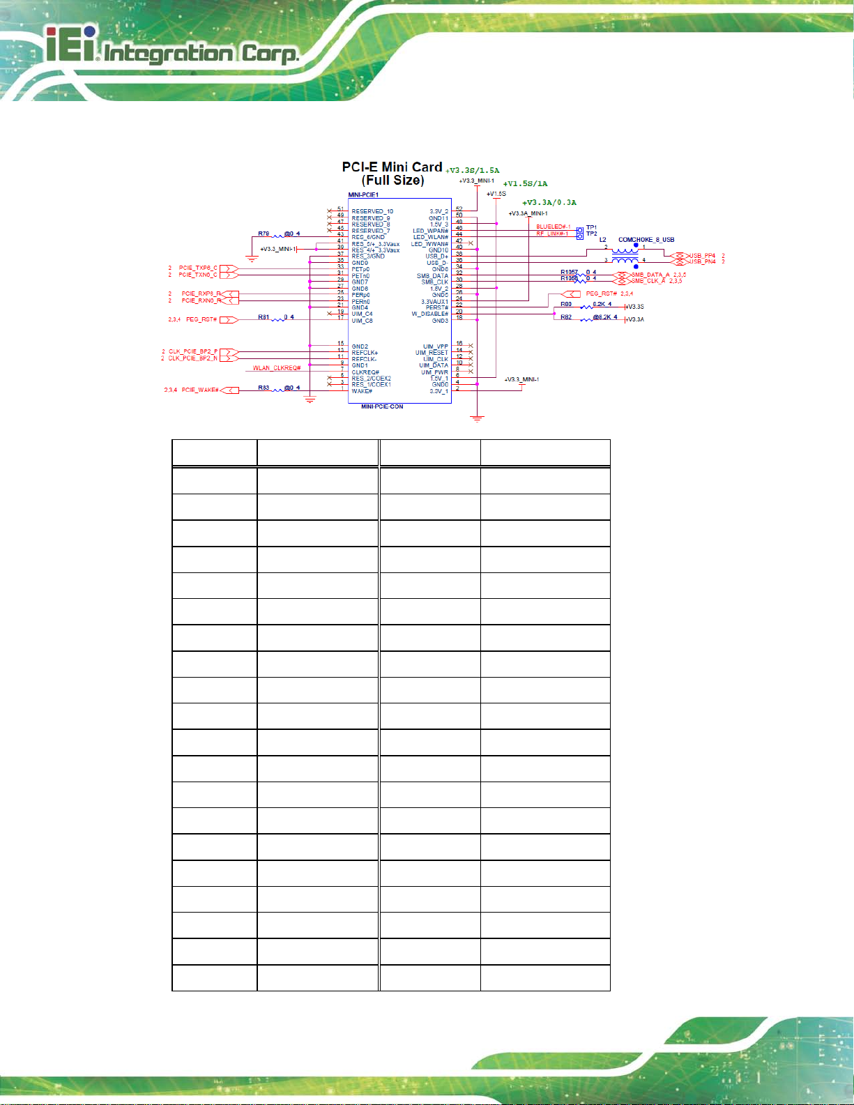
MINI-PCIE1:
Pin Description Pin Description
1 PCIE_WAKE# 2 VCC3
3 N/C 4 GND
5 N/C 6 1.5 V
7 WLAN_CLKREQ# 8 N/C
9 GND 10 N/C
11 CLK- 12 N/C
13 CLK+ 14 N/C
15 GND 16 N/C
17 PCIRST# 18 GND
19 N/C 20 VCC3
21 GND 22 PCIRST#
23 PCIE-RXN 24 VCC3
25 PCIE-RXP 26 GND
27 GND 28 1.5 V
29 GND 30 SMBCLK
31 PCIE-TXN 32 SMBDATA
33 PCIE-TXP 34 GND
35 GND 36 USBD37 GND 38 USBD+
39 VCC3 40 GND
Page 29

TANK-860-HM86 Embedded S ystem
Page 17
Pin Description Pin Description
41 VCC3 42 N/C
43 GND 44 RF_LINK#
45 N/C 46 BLUELED#
47 N/C 48 1.5 V
49 N/C 50 GND
51 N/C 52 VCC3
Figure 1-9: HPE-6S86 (for 6-slot model)
PWR1:
Pin Description
1 GND
2 GND
3 +12 V
4 +12 V
Page 30

TANK-860-HM86 Embedded S ystem
Page 18
USB1:
Pin Description
1 VCC
2 Data3 Data+
4 GND
MINI-PCIE1:
Pin Description Pin Description
1 PCIE_WAKE# 2 VCC3
3 N/C 4 GND
5 N/C 6 1.5 V
7 WLAN_CLKREQ# 8 N/C
9 GND 10 N/C
Page 31

TANK-860-HM86 Embedded S ystem
Page 19
Pin Description Pin Description
11 CLK- 12 N/C
13 CLK+ 14 N/C
15 GND 16 N/C
17 PCIRST# 18 GND
19 N/C 20 VCC3
21 GND 22 PCIRST#
23 PCIE-RXN 24 VCC3
25 PCIE-RXP 26 GND
27 GND 28 1.5 V
29 GND 30 SMBCLK
31 PCIE-TXN 32 SMBDATA
33 PCIE-TXP 34 GND
35 GND 36 USBD37 GND 38 USBD+
39 VCC3 40 GND
41 VCC3 42 N/C
43 GND 44 RF_LINK#
45 N/C 46 BLUELED#
47 N/C 48 1.5 V
49 N/C 50 GND
51 N/C 52 VCC3
The supported signals of the backplane slots are listed below.
Backplane Slot Signal
PCIe x16 PCIe x8
2-slot model
PCIe x16 PCIe x8
PCIe x16 PCIe x8
PCIe x16 PCIe x8
4-slot model
PCI PCI
6-slot model
PCI PCI
PCIe x16 PCIe x8
PCIe x4 PCIe x4
Page 32

TANK-860-HM86 Embedded S ystem
Page 20
Backplane Slot Signal
PCIe x4 PCIe x4
PCI PCI
PCI PCI
PCI PCI
Table 1-4: Supported Signals
The rated voltage and current of the backplanes are listed below.
120W/19V adaptor backplane total power limit:30W
Rated Voltage Rated Current
+5 V 4.0 A
+12 V 2.5 A
-12 V 0.1 A
+3.3 V 5.0 A
Table 1-5: Rated Voltage and Current
150W/12V adaptor backplane total power limit:50W
Rated Voltage Rated Current
+5 V 4.0 A
+12 V 4.0A
-12 V 0.1 A
+3.3 V 5.0 A
Table 1-6: Rated Voltage and Current
180W/19V adaptor backplane total power limit:70W
Rated Voltage Rated Current
+5 V 4.0 A
+12 V 5.5 A
Page 33

TANK-860-HM86 Embedded S ystem
Page 21
-12 V 0.1 A
+3.3 V 5.0 A
Table 1-7: Rated Voltage and Current
WARNING:
1. The system power consumption is 80W w/o add-on card.
2. The maximum total power of the backplane to support expansion
cards is different based on different adapter.
3. Please check your add-on card total consumption to choose suitable
power adapter.
NOTE:
When using an expansion card with high power consumption, it is
recommended to install an external power supply to the 12V power
input connector on the backplane.
The three types of backplane support standard PCI/PCIe cards with
maximum dimensions (WxL):110 x 230 mm.
The figure below shows how to connect an external power supply to the 12V power inp ut
connector on the backplane.
Page 34

TANK-860-HM86 Embedded S ystem
Page 22
Figure 1-10: Backplane Power
Page 35

TANK-860-HM86 Embedded S ystem
Page 23
1.9 Phys ical Dimens ions
The following sections describe the physical dimensions for each model of the
TANK-860-HM86 Series .
1.9.1 TANK-860-HM86 Phys ical Dimens ions (2-s lot)
The physical dimensions of the 2-slot TANK-860-HM86 are shown in Figure 1-10.
Figure 1-11: 2-slot TANK-860-HM86 Physical Dimensions (millimeters)
Page 36

TANK-860-HM86 Embedded S ystem
Page 24
1.9.2 TANK-860-HM86 Physical Dimens ions (4-slot)
The physical dimensions of the 4-slot TANK-860-HM86 are shown in Figure 1-12.
Figure 1-12: 4-slot TANK-860-HM86 Physical Dimensions (millimeters)
Page 37

TANK-860-HM86 Embedded S ystem
Page 25
1.9.3 TANK-860-HM86 Physical Dimens ions (6-slot)
The physical dimensions of the 6-slot TANK-860-HM86 are shown in Figure 1-13.
Figure 1-13: 6-slot TANK-860-HM86 Physical Dimensions (millimeters)
Page 38

TANK-860-HM86 Embedded S ystem
Page 26
Chapter
2
2 Unpacking
Page 39

TANK-860-HM86 Embedded S ystem
Page 27
may result in
2.1 Anti-static Precautions
WARNING:
Failure to take ESD precautions during installation
permanent damage to the TANK-860-HM86 Series and severe injury to
the user.
Electrostatic discharge (ESD) can cause serious damage to electronic components,
including the TANK-860-HM86 Series. Dry climates are especially susceptible to ESD. It is
therefore critical that whenever the TANK-860-HM86 Series or any other electrical
component is handled, the follo wing ant i-static precautions are strictly adhered to.
Wear an anti-static wristband: Wearing a simple anti-static wristband can
help to prevent ESD from damaging the board.
Self-grounding: Before handling the board touch any grounded conducting
material. During the time the board is handled, frequently touch any
conducting materials that are connected to the ground.
Use an anti-static pad: When configuring the TANK-860-HM86 Series, place
it on an antic-static pad. This reduces the possibility of ESD damaging the
TANK-860-HM 86 Seri es .
2.2 Unpacking Precautions
When the TANK-860-HM86 Series is unpacked, please do the following:
Follow the anti-static precautions outlined in Section 2.1.
Make sure the packing box is facing upwards so the TANK-860-HM86 Series
does not fall out of the box.
Make sure all the components shown in Section 2.3 are present.
Page 40

TANK-860-HM86 Embedded S ystem
Page 28
2.3 Unpacking Checklist
NOTE:
If some of the components listed in the checklist below are missing,
please do not proceed with the installation. Contact the IEI res eller or
vendor you purchas ed the TANK-860-HM86 Series from or contac t an
IEI sales representative directly. To contact an IEI sales representative,
please send an email to
The TANK-860-HM86 Ser i es is shipped with the following components:
Quantity Item and Part Number Ima g e
Standard
1 TANK-860-HM86 Series
2 Mounting Brackets
sales@ieiworld.com.
1 One Key Recovery CD
(P/N: 7B000-000724-RS)
1 User Manual and Driver CD
 Loading...