

Page 1

SPCIE-C236 Full-size PICMG 1.3 CPU Card
MODEL:
SPCIE-C236
Full-Size PICMG 1.3 CPU Card Supports LGA1151 Intel® Xeon®
E3 v5/v6, 6th/7th Generation Intel® Core™ i7/i5/i3, Pentium® or
Celeron® CPU, Intel® C236 Chipset, DDR4, Dual Intel® PCIe GbE,
VGA, iDP, USB 3.0, SATA 6Gb/s, mSATA, Intel® AMT and RoHS
User Manual
Rev. 1.02 – November 13, 2017
Page i
Page 2

SPCIE-C236 Full-size PICMG 1.3 CPU Card
Revision
Date Version Changes
November 13, 2017
September 11, 2017 1.01 Added Intel® Core™ i7/i5 as supported CPU
October 27, 2016
1.02 Updated supported CPUs
1.00 Initial release
Page ii
Page 3

SPCIE-C236 Full-size PICMG 1.3 CPU Card
COPYRIGHT NOTICE
The information in this document is subject to change without prior notice in order to
improve reliability, design and function and does not represent a commitment on the part
of the manufacturer.
In no event will the manufacturer be liable for direct, indirect, special, incidental, or
consequential damages arising out of the use or inability to use the product or
documentation, even if advised of the possibility of such damages.
This document contains proprietary information protected by copyright. All rights are
Copyright
reserved. No part of this manual may be reproduced by any mechanical, electronic, or
other means in any form without prior written permission of the manufacturer.
TRADEMARKS
All registered trademarks and product names mentioned herein are used for identification
purposes only and may be trademarks and/or registered trademarks of their respective
owners.
Page iii
Page 4

SPCIE-C236 Full-size PICMG 1.3 CPU Card
Manual Conventions
WARNING
Warnings appear where overlooked details may cause damage to the
equipment or result in personal injury. Warnings should be taken
seriously.
CAUTION
Cautionary messages should be heeded to help reduce the chance of
losing data or damaging the product.
NOTE
These messages inform the reader of essential but non-critical
information. These messages should be read carefully as any directions
or instructions contained therein can help avoid making mistakes.
HOT SURFACE
This symbol indicates a hot surface that should not be touched without
taking care.
Page iv
Page 5

SPCIE-C236 Full-size PICMG 1.3 CPU Card
Table of Contents
1 INTRODUCTION.......................................................................................................... 1
1.1 INTRODUCTION........................................................................................................... 2
1.2 MODEL VARIATIONS................................................................................................... 3
1.3 FEATURES................................................................................................................... 3
1.4 CONNECTORS ............................................................................................................. 4
1.5 DIMENSIONS............................................................................................................... 5
1.6 DATA FLOW................................................................................................................ 6
1.7 TECHNICAL SPECIFICATIONS ...................................................................................... 7
2 PACKING LIST........................................................................................................... 10
2.1 ANTI-STATIC PRECAUTIONS.......................................................................................11
2.2 UNPACKING PRECAUTIONS........................................................................................11
2.3 PACKING LIST........................................................................................................... 12
2.4 OPTIONAL ITEMS...................................................................................................... 13
3 CONNECTORS ........................................................................................................... 16
3.1 PERIPHERAL INTERFACE CONNECTORS..................................................................... 17
3.1.1 SPCIE-C236 Layout......................................................................................... 17
3.1.2 Peripheral Interface Connectors ..................................................................... 18
3.1.3 External Interface Panel Connectors............................................................... 19
3.2 INTERNAL PERIPHERAL CONNECTORS...................................................................... 20
3.2.1 +12V ATX Power Connector........................................................................... 20
3.2.2 Audio Kit Connector........................................................................................ 20
3.2.3 Battery Connector............................................................................................ 21
3.2.4 Chassis Intrusion Connector............................................................................ 22
3.2.5 CRT FW Update Connector............................................................................. 23
3.2.6 DDR4 DIMM Sockets ...................................................................................... 23
3.2.7 Digital I/O Connector...................................................................................... 24
3.2.8 EC Debug Connector....................................................................................... 25
3.2.9 Fan Connector (CPU)...................................................................................... 26
Page v
Page 6

3.2.10 Fan Connectors (System)............................................................................... 26
3.2.11 Front Panel Connector................................................................................... 27
3.2.12 I2C Connector................................................................................................ 28
3.2.13 Internal DisplayPort Connector.................................................................... 29
3.2.14 iRIS-2400 Module Slot (SPCIE-C236-i2-R10 Only) ..................................... 30
3.2.15 Keyboard and Mouse Connector................................................................... 30
3.2.16 LAN LED Connectors.................................................................................... 31
3.2.17 Parallel Port Connector ................................................................................ 32
3.2.18 PCIe Mini Slot................................................................................................ 33
3.2.19 Power Button ................................................................................................. 35
3.2.20 RS-232 Serial Port Connectors...................................................................... 35
3.2.21 RS-232/422/485 Serial Port Connectors ....................................................... 36
3.2.22 SATA 6Gb/s Drive Connector ........................................................................ 37
3.2.23 SMBus Connector .......................................................................................... 38
SPCIE-C236 Full-size PICMG 1.3 CPU Card
3.2.24 SPI Flash Connector...................................................................................... 39
3.2.25 SPI Flash Connector, EC............................................................................... 40
3.2.26 TPM Connector.............................................................................................. 41
3.2.27 USB 2.0 Connectors....................................................................................... 42
3.2.28 USB 2.0 Connector (Type A).......................................................................... 43
3.2.29 USB 3.0 Connector ........................................................................................ 44
3.3 EXTERNAL PERIPHERAL INTERFACE CONNECTOR PANEL ......................................... 45
3.3.1 Ethernet Connectors ........................................................................................ 45
3.3.2 USB 3.0 Connectors......................................................................................... 46
3.3.3 VGA Connector................................................................................................ 46
4 INSTALLATION ......................................................................................................... 48
4.1 ANTI-STATIC PRECAUTIONS...................................................................................... 49
4.2 INSTALLATION CONSIDERATIONS.............................................................................. 49
4.3 SOCKET LGA1151 CPU INSTALLATION ................................................................... 51
4.4 SOCKET LGA1151 COOLING KIT INSTALLATION ..................................................... 54
4.5 DIMM INSTALLATION.............................................................................................. 56
4.6 IRIS-2400 MODULE INSTALLATION (OPTIONAL)...................................................... 57
4.7 FULL-SIZE PCIE MINI CARD INSTALLATION ............................................................. 58
4.8 HALF-SIZE PCIE MINI CARD INSTALLATION............................................................. 59
4.9 SYSTEM CONFIGURATION......................................................................................... 61
Page vi
Page 7

SPCIE-C236 Full-size PICMG 1.3 CPU Card
4.9.1 AT/ATX Power Mode Setting........................................................................... 61
4.9.2 Clear CMOS Button......................................................................................... 62
4.9.3 PCIe x4 Channel Mode Setup.......................................................................... 62
4.9.4 PCIe x16 Channel Mode Setup........................................................................ 63
4.9.5 Flash Descriptor Security Override Jumper.................................................... 64
4.9.6 USB Power Selection....................................................................................... 65
4.9.7 mSATA Setup.................................................................................................... 66
4.10 INTERNAL PERIPHERAL DEVICE CONNECTIONS...................................................... 66
4.10.1 SATA Drive Connection ................................................................................. 66
4.11 ADDING USB 3.0 DRIVERS TO A WINDOWS 7 INSTALLATION IMAGE ...................... 68
4.12 INTEL
®
AMT SETUP PROCEDURE........................................................................... 70
4.13 IPMI SETUP PROCEDURE (SPCIE-C236-I2-R10 ONLY)......................................... 71
4.13.1 Managed System Hardware Setup ................................................................. 71
4.13.2 Using the IEI iMAN Web GUI........................................................................ 71
5 BIOS.............................................................................................................................. 74
5.1 INTRODUCTION......................................................................................................... 75
5.1.1 Starting Setup................................................................................................... 75
5.1.2 Using Setup...................................................................................................... 75
5.1.3 Getting Help..................................................................................................... 76
5.1.4 Unable to Reboot after Configuration Changes.............................................. 76
5.1.5 BIOS Menu Bar................................................................................................ 76
5.2 MAIN........................................................................................................................ 76
5.3 ADVANCED............................................................................................................... 78
5.3.1 T rusted Computing........................................................................................... 79
5.3.2 ACPI Settings................................................................................................... 80
5.3.3 AMT Configuration.......................................................................................... 81
5.3.4 Super IO Configuration ................................................................................... 82
5.3.4.1 Serial Port n Configuration....................................................................... 83
5.3.4.2 Parallel Port Configuration....................................................................... 87
5.3.5 iWDD H/W Monitor......................................................................................... 88
5.3.5.1 Smart Fan Mode Configuration................................................................ 90
5.3.6 RTC Wake Settings........................................................................................... 91
5.3.7 Serial Port Console Redirection...................................................................... 92
5.3.7.1 Legacy Console Redirection Settings....................................................... 95
Page vii
Page 8

5.3.8 CPU Configuration.......................................................................................... 96
5.3.9 SATA Configuration.......................................................................................... 98
5.3.10 NVMe Configuration...................................................................................... 99
5.3.11 USB Configuration....................................................................................... 100
5.3.12 iEi Feature................................................................................................... 101
5.4 CHIPSET ................................................................................................................. 102
5.4.1 System Agent (SA) Configuration .................................................................. 103
5.4.1.1 Graphics Configuration........................................................................... 104
5.4.1.2 PEG Port Configuration.......................................................................... 106
5.4.1.3 Memory Configuration ........................................................................... 107
5.4.2 PCH-IO Configuration .................................................................................. 108
5.4.2.1 PCI Express Configuration......................................................................110
5.4.2.2 HD Audio Configuration..........................................................................112
5.5 SECURITY................................................................................................................113
SPCIE-C236 Full-size PICMG 1.3 CPU Card
5.6 BOOT.......................................................................................................................114
5.7 SAVE & EXIT...........................................................................................................116
5.8 SERVER MGMT (SPCIE-C236-I2-R10 ONLY) .........................................................117
5.8.1 System Event Log............................................................................................117
5.8.2 BMC Network Configuration..........................................................................119
6 SOFTWARE DRIVERS............................................................................................ 121
6.1 AVAILABLE SOFTWARE DRIVERS ............................................................................ 122
6.2 SOFTWARE INSTALLATION ...................................................................................... 122
A REGULATORY COMPLIANCE............................................................................ 124
B PRODUCT DISPOSAL............................................................................................ 126
C BIOS OPTIONS........................................................................................................ 128
D TERMINOLOGY ..................................................................................................... 132
E DIGITAL I/O INTERFACE..................................................................................... 136
E.1 INTRODUCTION ...................................................................................................... 137
E.2 ASSEMBLY LANGUAGE SAMPLE 1.......................................................................... 138
E.3 ASSEMBLY LANGUAGE SAMPLE 2.......................................................................... 138
F WATCHDOG TIMER............................................................................................... 139
Page viii
Page 9

SPCIE-C236 Full-size PICMG 1.3 CPU Card
G HAZARDOUS MATERIALS DISCLOSURE....................................................... 142
Page ix
Page 10

SPCIE-C236 Full-size PICMG 1.3 CPU Card
List of Figures
Figure 1-1: SPCIE-C236..................................................................................................................2
Figure 1-2: Connectors ..................................................................................................................4
Figure 1-3: SPCIE-C236 Dimensions (mm)..................................................................................5
Figure 1-4: Data Flow Diagram......................................................................................................6
Figure 3-1: Peripheral Interface Connectors .............................................................................17
Figure 3-2: +12V ATX Power Connector Pinout Location ........................................................20
Figure 3-3: Audio Connector Location.......................................................................................21
Figure 3-4: Battery Connector Location.....................................................................................22
Figure 3-5: Chassis Intrusion Connector Location...................................................................22
Figure 3-6: CRT FW Update Connector Location......................................................................23
Figure 3-7: DDR4 DIMM Socket Locations.................................................................................24
Figure 3-8: Digital I/O Connector Location ................................................................................24
Figure 3-9: EC Debug Connector Location................................................................................25
Figure 3-10: CPU Fan Connector Location................................................................................26
Figure 3-11: System Fan Connector Location...........................................................................27
Figure 3-12: Front Panel Connector Location ...........................................................................27
Figure 3-13: I2C Connector Location ..........................................................................................28
Figure 3-14: Internal DisplayPort Connector Location.............................................................29
Figure 3-15: iRIS-2400 Module Slot Location ............................................................................30
Figure 3-16: Keyboard and Mouse Connector Location...........................................................31
Figure 3-17: LAN LED Connector Locations .............................................................................31
Figure 3-18: Parallel Port Connector Location..........................................................................32
Figure 3-19: PCIe Mini Slot Location..........................................................................................33
Figure 3-20: Power Button Location...........................................................................................35
Figure 3-21: RS-232 Serial Port Connector Locations..............................................................35
Figure 3-22: RS-232/422/485 Serial Port Connector Locations................................................36
Figure 3-23: SATA 6Gb/s Drive Connector Locations..............................................................38
Figure 3-24: SMBus Connector Location...................................................................................39
Figure 3-25: SPI Flash Connector Location...............................................................................39
Figure 3-26: SPI EC Flash Connector Location.........................................................................40
Page x
Page 11

SPCIE-C236 Full-size PICMG 1.3 CPU Card
Figure 3-27: TPM Connector Location........................................................................................41
Figure 3-28: USB 2.0 Connector Locations ...............................................................................42
Figure 3-29: USB 2.0 Connector (Type A) Pinout Location......................................................43
Figure 3-30: USB 3.0 Connector Location .................................................................................44
Figure 3-31: External Peripheral Interface Connector..............................................................45
Figure 3-32: Ethernet Connector.................................................................................................45
Figure 3-33: VGA Connector .......................................................................................................47
Figure 4-1: Disengage the CPU Socket Load Lever..................................................................51
Figure 4-2: Remove Protective Cover.........................................................................................52
Figure 4-3: Insert the Socket LGA1151 CPU..............................................................................53
Figure 4-4: Close the Socket LGA1151 ......................................................................................53
Figure 4-5: Cooling Kit Support Bracket....................................................................................55
Figure 4-6: DIMM Installation.......................................................................................................56
Figure 4-7: iRIS-2400 Module Installation ..................................................................................57
Figure 4-8: Removing the Retention Screw...............................................................................58
Figure 4-9: Inserting the Full-size PCIe Mini Card into the Slot at an Angle..........................58
Figure 4-10: Securing the Full-size PCIe Mini Card ..................................................................59
Figure 4-11: Installing the Standoff ............................................................................................60
Figure 4-12: Inserting the Half-size PCIe Mini Card into the Slot at an Angle........................60
Figure 4-13: Securing the Half-size PCIe Mini Card..................................................................61
Figure 4-14: AT/ATX Power Mode Switch Location..................................................................61
Figure 4-15: Clear CMOS Button Location.................................................................................62
Figure 4-16: BIOS Switch Location.............................................................................................62
Figure 4-17: Flash Descriptor Security Override Jumper Location ........................................64
Figure 4-18: mSATA Setup Jumper Location............................................................................66
Figure 4-19: SATA Drive Cable Connection...............................................................................67
Figure 4-20: SATA Power Drive Connection..............................................................................68
Figure 4-21: Windows 7 USB 3.0 Creator Utility........................................................................69
Figure 4-22: Update Process is Complete .................................................................................70
Figure 4-23: IEI iMAN Web Address............................................................................................72
Figure 4-24: IEI iMAN Web GUI....................................................................................................73
Figure 6-1: Available Drivers.................................................................................................... 123
Page xi
Page 12

SPCIE-C236 Full-size PICMG 1.3 CPU Card
List of Tables
Table 1-1: SPCIE-C236 Model Variations .....................................................................................3
Table 1-2: SPCIE-C236 Specifications..........................................................................................9
Table 2-1: Packing List.................................................................................................................13
Table 2-2: Optional Items.............................................................................................................15
Table 3-1: Peripheral Interface Connectors...............................................................................19
Table 3-2: External Peripheral Connectors................................................................................19
Table 3-3: +12V ATX Power Connector Pinouts........................................................................20
Table 3-4: Audio Connector Pinouts ..........................................................................................21
Table 3-5: Battery Connector Pinouts........................................................................................22
Table 3-6: Chassis Intrusion Connector Pinouts......................................................................22
Table 3-7: CRT FW Update Connector Pinouts.........................................................................23
Table 3-8: Digital I/O Connector Pinouts....................................................................................24
Table 3-9: EC Debug Connector Pinouts ...................................................................................25
Table 3-10: CPU Fan Connector Pinouts ...................................................................................26
Table 3-11: System Fan (SYS_FAN1) Connector Pinouts........................................................27
Table 3-12: Front Panel Connector Pinouts...............................................................................28
Table 3-13: I2C Connector Pinouts..............................................................................................28
Table 3-14: Internal DisplayPort Connector Pinouts ................................................................29
Table 3-15: Keyboard and Mouse Connector Pinouts..............................................................31
Table 3-16: LAN1 LED Connector (LED_LAN1) Pinouts...........................................................32
Table 3-17: LAN2 LED Connector (LED_LAN2) Pinouts...........................................................32
Table 3-18: Parallel Port Connector Pinouts .............................................................................33
Table 3-19: PCIe Mini Slot Pinouts..............................................................................................34
Table 3-20: RS-232 Serial Port Connector Pinouts...................................................................36
Table 3-21: RS-232/422/485 Serial Port Connector Pinouts.....................................................37
Table 3-22: DB-9 RS-232/422/485 Pinouts..................................................................................37
Table 3-23: SATA 6Gb/s Drive Connector Pinouts....................................................................38
Table 3-24: SMBus Connector Pinouts ......................................................................................39
Table 3-25: SPI Flash Connector Pinouts ..................................................................................40
Table 3-26: SPI EC Flash Connector Pinouts ............................................................................40
Page xii
Page 13

SPCIE-C236 Full-size PICMG 1.3 CPU Card
Table 3-27: TPM Connector Pinouts...........................................................................................41
Table 3-28: USB 2.0 Connector Pinouts.....................................................................................42
Table 3-29: USB 2.0 Connector (Type A) Pinouts .....................................................................43
Table 3-30: USB 3.0 Connector Pinouts.....................................................................................44
Table 3-31: LAN Pinouts ..............................................................................................................45
Table 3-32: USB 3.0 Port Pinouts................................................................................................46
Table 3-33: VGA Connector Pinouts...........................................................................................47
Table 4-1: AT/ATX Power Mode Switch Settings.......................................................................61
Table 4-2: BIOS Switch Settings.................................................................................................62
Table 4-3: PCIe x16 Channel Mode Setup..................................................................................63
Table 4-4: Flash Descriptor Security Override Jumper Settings.............................................64
Table 4-5: BIOS Options and Configured USB Ports................................................................65
Table 4-6: USB Power Source Setup..........................................................................................65
Table 4-7: mSATA Setup Jumper Settings.................................................................................66
Table 5-1: BIOS Navigation Keys................................................................................................76
Table 5-2: BIOS Options and Configured USB Ports............................................................. 109
Page xiii
Page 14

SPCIE-C236 Full-size PICMG 1.3 CPU Card
BIOS Menus
BIOS Menu 1: Main.......................................................................................................................77
BIOS Menu 2: Advanced..............................................................................................................78
BIOS Menu 3: Trusted Computing..............................................................................................79
BIOS Menu 4: ACPI Configuration..............................................................................................80
BIOS Menu 5: AMT Configuration...............................................................................................81
BIOS Menu 6: Super IO Configuration........................................................................................82
BIOS Menu 7: Serial Port n Configuration Menu.......................................................................83
BIOS Menu 8: Parallel Port Configuration Menu.......................................................................87
BIOS Menu 9: iWDD H/W Monitor ...............................................................................................89
BIOS Menu 10: Smart Fan Mode Configuration ........................................................................90
BIOS Menu 11: RTC Wake Settings............................................................................................91
BIOS Menu 12: Serial Port Console Redirection.......................................................................92
BIOS Menu 13: Legacy Console Redirection Settings .............................................................95
BIOS Menu 14: CPU Configuration.............................................................................................96
BIOS Menu 15: SATA Configuration...........................................................................................98
BIOS Menu 16: NVMe Configuration...........................................................................................99
BIOS Menu 17: USB Configuration.......................................................................................... 100
BIOS Menu 18: iEi Feature........................................................................................................ 101
BIOS Menu 19: Chipset............................................................................................................. 102
BIOS Menu 20: System Agent (SA) Configuration................................................................. 103
BIOS Menu 21: Graphics Configuration.................................................................................. 104
BIOS Menu 22: PEG Port Configuration.................................................................................. 106
BIOS Menu 23: Memory Configuration.................................................................................... 107
BIOS Menu 24: PCH-IO Configuration..................................................................................... 108
BIOS Menu 25: PCI Express Configuration (For BIOS1)....................................................... 110
BIOS Menu 26: PCI Express Configuration (For BIOS2)....................................................... 110
BIOS Menu 27: PCIEX1 Slot/PCIEX4 Slot/MPCIE Slot............................................................ 111
BIOS Menu 28: HD Audio Configuration................................................................................. 112
BIOS Menu 29: Security............................................................................................................ 113
BIOS Menu 30: Boot.................................................................................................................. 114
Page xiv
Page 15

SPCIE-C236 Full-size PICMG 1.3 CPU Card
BIOS Menu 31: Save & Exit....................................................................................................... 116
BIOS Menu 32: Server Mgmt .................................................................................................... 117
BIOS Menu 33: System Event Log........................................................................................... 117
BIOS Menu 34: System Event Log........................................................................................... 119
Page xv
Page 16

SPCIE-C236 Full-size PICMG 1.3 CPU Card
1 Introduction
Chapter
1
Page 1
Page 17

1.1 Introduction
Figure 1-1: SPCIE-C236
The SPCIE-C236 is a full-size PICMG 1.3 CPU card. It accepts a Socket LGA1151 Intel®
Xeon® E3 v5/v6, 6th/7th generation Intel® Core™ i7/i5/i3, Pentium® or Celeron®
processor and supports four 288-pin 2133 MHz dual-channel DDR4 DIMM modules up to
SPCIE-C236 Full-size PICMG 1.3 CPU Card
64 GB.
The SPCIE-C236 provides two GbE interfaces through the Intel® I219LM (with Intel®
AMT 11.0 support) and the Intel® I210 PCIe controllers. The integrated Intel® C236
chipset supports six SATA 6Gb/s drives with RAID 0/1/5/10 function. In addition, the
SPCIE-C236 includes VGA and iDP interfaces for dual independent display.
Two USB 3.0 on the rear panel, two USB 3.0 by internal box header, six USB 2.0 by pin
headers, one USB 2.0 by internal Type A connector, two RS-232, two RS-232/422/485
and one PCIe Mini interface provide flexible expansion options. High Definition Audio
(HDA) support ensures HDA devices can be easily implemented on the SPCIE-C236.
Page 2
Page 18

SPCIE-C236 Full-size PICMG 1.3 CPU Card
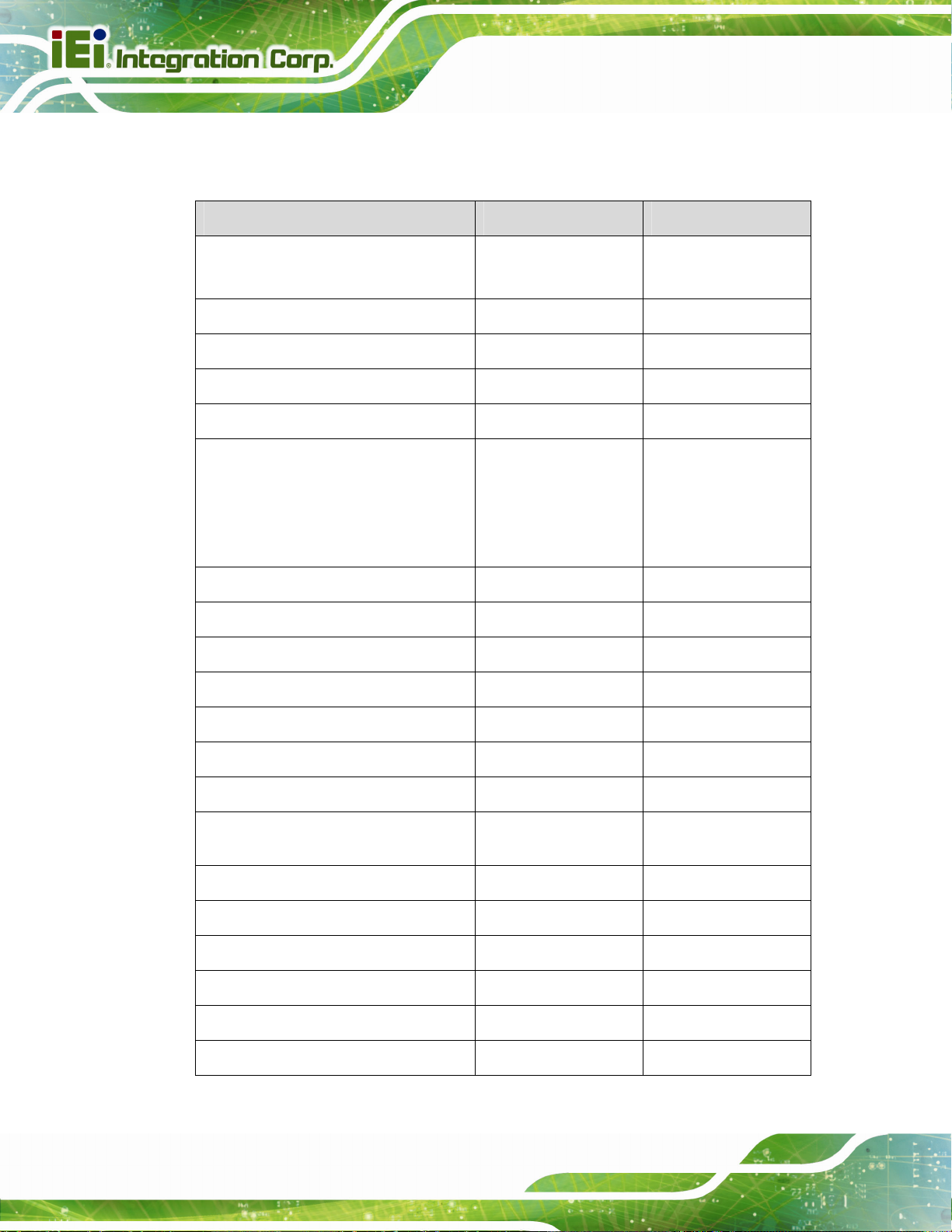
1.2 Model Variations
The model variations of the SPCIE-C236 series are listed below.
Model No. Supported CPU iRIS-2400 Module Slot
SPCIE-C236-R10
SPCIE-C236-i2-R10
Table 1-1: SPCIE-C236 Model Variations
1.3 Features
Some of the SPCIE-C236 motherboard features are listed below:
Full-size PICMG 1.3 CPU card
LGA1151 Intel® Xeon® E3 v5/v6, 6th/7th generation Intel® Core™ i7/i5/i3,
Intel® C236 chipset
Four 288-pin 2133/1867 MHz dual-channel ECC/non-ECC unbuffered DDR4
Two Intel® PCIe GbE connectors (LAN1 with Intel® AMT 11.0 support)
Dual independent display by VGA and iDP interfaces
One full-size/half-size PCIe Mini slot supports mSATA
LGA1151 Intel® Xeon® E3 v5/v6,
6th/7th generation Intel® Core™
i7/i5/i3, Pentium® or Celeron®
Pentium® or Celeron® processor supported
SDRAM DIMMs support (system max. 64 GB)
No
Yes
Six SATA 6Gb/s connectors support RAID 0, 1, 5, 10 function
Two USB 3.0 ports on the rear I/O
Two USB 3.0 ports via internal box header
Six USB 2.0 ports via internal pin headers
One USB 2.0 via internal Type A connec tor
Two RS-232 serial ports
Two RS-232/422/485 serial ports
TPM V1.2 hardware security function supported by TPM module
High Definition Audio
RoHS compliant
Page 3
Page 19

1.4 Connectors
The connectors on the SPCIE-C236 are shown in the figure below.
SPCIE-C236 Full-size PICMG 1.3 CPU Card
Page 4
Figure 1-2: Connectors
Page 20

SPCIE-C236 Full-size PICMG 1.3 CPU Card
1.5 Dimensions
The main dimensions of the SPCIE-C236 are shown in the diagram below.
Figure 1-3: SPCIE-C236 Dimensions (mm)
Page 5
Page 21

1.6 Data Flow
Figure 1-4 shows the data flow between the system chipset, the CPU and other
components installed on the motherboard.
SPCIE-C236 Full-size PICMG 1.3 CPU Card
Page 6
Figure 1-4: Data Flow Diagram
Page 22
SPCIE-C236 Full-size PICMG 1.3 CPU Card
1.7 Technical Specifications
The SPCIE-C236 technical specifications are listed below.
Specification/Model SPCIE-C236
Form Factor
CPU Supported
PCH
Memory
Graphics Engine
Display Output
Full-size PICMG 1.3 CPU card
LGA1151 Intel® Xeon® E3 v5/v6, 6th/7th generation Intel®
Core™ i7/i5/i3, Pentium® or Celeron® CPU
Intel® C236
Four 288-pin 2133/1867 MHz dual-channel ECC/non-ECC
unbuffered DDR4 SDRAM DIMMs supported (system max.
64 GB)
Intel® HD Graphics Gen9 engine supports DirectX 11/12,
OpenCL 2.x and OpenGL 4.3/4.4
Decode/encode for HEVC, VP8, VP9, VDENC
Supports dual independent display
One VGA (via Chrontel CH7517, up to 1920x1200@60 Hz)
One iDP interface for HDMI, LVDS, VGA, DVI and
DisplayPort (up to 3840x2160@60 Hz)
LAN1: Intel® I219LM PCIe GbE controller with Intel® AMT
Ethernet Controllers
LAN2: Intel® I210 PCIe GbE controller
Audio
BIOS
Expansions
Supports 7.1-channel HD audio by IEI AC-KIT-892HD kit
UEFI BIOS
One full-size/half-size PCIe Mini card slot (supports mSATA,
co-lay SATA port 6)
4 x PCI link via golden finger
16-lane PCIe link from CPU via golden finger:
Supports one PCIe x16, or two PCIe x8, or two PCIe x4 + o ne
PCIe x8 slots on the backplane (configured via BIOS)
4-lane PCIe link from PCH via golden finger:
Supports four PCIe x1 slots or one PCIe x4 slot on the
backplane (configured via BIOS switch)
11.0 support
Page 7
Page 23
SPCIE-C236 Full-size PICMG 1.3 CPU Card
Super I/O Controller
Embedded Controller
Watchdog Timer
I/O Interface Connectors
Audio Connector
Chassis Intrusion
Digital I/O
Ethernet
Fan
Front Panel
I2C
iRIS (IEI Remote
Intelligent System)
Fintek F81866D-I
ITE IT8528E
Software programmable supports 1~2 55 sec. system reset
One audio connector (10-pin header)
One 2-pin header
8-bit digital I/O (10-pin header)
Two RJ-45 port s
One 4-pin CPU smart fan connector
One 3-pin system smart fan connector
One 14-pin header (power LED, HDD LED, speaker, power
button, reset button)
One 4-pin wafer connector
One iRIS-2400 module slot (SPCIE-C236-i2-R10 only)
Internal DisplayPort
Keyboard and Mouse
LAN LED
Parallel Port
Serial ATA
Serial Ports
SMBus
TPM
USB 2.0
One 20-pin box header
One internal keyboard and mouse connector (6-pin wafer)
Two 2-pin headers for LAN1 LED and LAN2 LED
One parallel port via internal 26-pin box header
Six SATA 6Gb/s connectors (support RAID 0, 1, 5, 10)
Two RS-232 via internal 10-pin box headers
Two RS-232/422/485 via internal 10-pin box headers
One 4-pin wafer connector
One via 20-pin header
Six USB 2.0 ports by three internal pin headers
One USB 2.0 port by internal Type A connector
Page 8
Page 24
SPCIE-C236 Full-size PICMG 1.3 CPU Card
Two USB 3.0 ports on rear panel
Two USB 3.0 ports via internal box header
* The Windows® 7 installation media does not include native
USB 3.0
Environmental and Power Specifications
driver support for USB 3.0. In order to use the USB keyboard
or mouse connected to a USB 3.0 port during OS installation,
the user has to update the Windows® 7 installation image so
that it contains USB 3.0 drivers. Please refer to Section
for detailed installation procedures.
4.11
Power Supply
Power Consumption
Operating
Temperature
Storage Temperature
Operating Humidity
Physical Specifications
Dimensions
Weight (GW/NW)
Table 1-2: SPCIE-C236 Specifications
5V/12V, AT/ATX power support
5V@3.31A, 12V@6.97A, 3.3V@1.21A, 5VSB@0.16A
(3.6 GHz Intel® Xeon® E3-1275 v5 CPU with four 16 GB
2133 MHz DDR4 memory)
-20ºC ~ 60ºC
-30ºC ~ 70ºC
5% ~ 95% (non-condensing)
338 mm x 126 mm
1000 g/420 g
Page 9
Page 25

SPCIE-C236 Full-size PICMG 1.3 CPU Card
Chapter
2
2 Packing List
Page 10
Page 26

SPCIE-C236 Full-size PICMG 1.3 CPU Card
2.1 Anti-static Precautions
WARNING!
Static electricity can destroy certain electronics. Make sure to follow the
ESD precautions to prevent damage to the product, and injury to the
user.
Make sure to adhere to the following guidelines:
Wear an anti-static wristband: Wearing an anti-static wristband can prevent
electrostatic discharge.
Self-grounding: Touch a grounded conductor every few minutes to discharge
any excess static buildup.
Use an anti-static pad: When configuring any circuit board, place it on an
anti-static mat.
Only handle the edges of the PCB: Don't touch the surface of the
motherboard. Hold the motherboard by the edges when handling.
2.2 Unpacking Precautions
When the SPCIE-C236 is unpacked, please do the following:
Follow the anti-static guidelines above.
Make sure the packing box is facing upwards whe n opening.
Make sure all the packing list items are present.
Page 11
Page 27

2.3 Packing List
NOTE:
If any of the components listed in the checklist below are missing, do
not proceed with the installation. Contact the IEI reseller or vendor the
SPCIE-C236 was purchased from or contact an IEI sales
representative directly by sending an email to 32sales@ieiworld.com.
The SPCIE-C236 is shipped with the following components:
Quantity Item and Part Number Image
1 SPCIE-C236 CPU card
SPCIE-C236 Full-size PICMG 1.3 CPU Card
1 SATA cable
(P/N: 32000-062800-RS)
1 Mini jumper pack
1 Standoff and screw (for half-size PCIe Mini
card)
1 Utility CD
1 One Key Recovery CD
Page 12
Page 28

SPCIE-C236 Full-size PICMG 1.3 CPU Card
Quantity Item and Part Number Image
1 Quick installation guide
Table 2-1: Packing List
2.4 Optional Items
The following are optional components which may be separately purchased:
Item and Part Number Image
RS-232/422/485 cable, 230 mm, P=2.54
(P/N: 32205-000702-100-RS)
PS/2 KB/MS Y-cable with bracket
(P/N: 19800-000075-RS)
SATA power cable
(P/N: 32102-000100-200-RS)
LPT cable
(P/N: 32200-015100-RS)
7.1-channel HD audio kit with Realtek ALC892 audio
codec supporting dual audio stream
(P/N: AC-KIT-892HD-R10)
LGA1150 cooler kit (high-performance compatible, 95W)
(P/N: CF-1 150SA-R10)
Page 13
Page 29

Item and Part Number Image
LGA1150 cooler kit (high-performance compatible, 65W)
(P/N: CF-1150SB-R11)
LGA1150 cooler kit (1U chassis compatible, 65W)
(P/N: CF-1150SC-R20)
LGA1150 cooler kit (high-performance compatible, 95W)
(P/N: CF-1150SE-R11)
SPCIE-C236 Full-size PICMG 1.3 CPU Card
LGA1150 cooler kit (1U chassis compatible, 54W)
(P/N: CF-1 150SF-R10)
DisplayPort to HDMI converter board (for IEI iDP
connector)
(P/N: DP-HDMI-R10)
DisplayPort to LVDS converter board (for IEI iDP
connector)
(P/N: DP-LVDS-R10)
DisplayPort to VGA converter board (fo r IEI iDP connector)
(P/N: DP-VGA-R10)
Page 14
Page 30

SPCIE-C236 Full-size PICMG 1.3 CPU Card
Item and Part Number Image
DisplayPort to DVI-D converter board (for IEI iDP
connector)
(P/N: DP-DVI-R10)
DisplayPort to DisplayPort converter board (for IEI iDP
connector)
(P/N: DP-DP-R10)
SATA to IDE/Com pactFlash® converter board
(P/N: SAIDE-KIT01-R10)
Table 2-2: Optional Items
Page 15
Page 31

SPCIE-C236 Full-size PICMG 1.3 CPU Card
Chapter
3
3 Connectors
Page 16
Page 32

SPCIE-C236 Full-size PICMG 1.3 CPU Card
3.1 Peripheral Interface Connectors
This chapter details all the peripheral interface connectors.
3.1.1 SPCIE-C236 Layout
The figure below shows all the peripheral interface connectors.
Figure 3-1: Peripheral Interface Connectors
Page 17
Page 33
3.1.2 Peripheral Interface Connectors
The table below lists all the connectors on the board.
Connector Type Label
SPCIE-C236 Full-size PICMG 1.3 CPU Card
+12V ATX power supply connector
Audio kit connector 10-pin header J_AUDIO1
Battery connector 2-pin wafer BAT1
Chassis intrusion connector 2-pin header CHASSIS1
CRT FW update 3-pin header J_CRTFW1
DDR4 DIMM sockets 288-pin socket
Digital I/O connector 10-pin header DIO1
EC debug connector 18-pin header CN1
Fan connector (CPU) 4-pin wafer CPU_FAN1
Fan connector (system) 3-pin wafer SYS_FAN1
4-pin Molex power
CPU12V1
connector
CHA_DIMM0,
CHA_DIMM1,
CHB_DIMM0,
CHB_DIMM1
Page 18
Front panel connector 14-pin header F_PANEL1
I2C connector 4-pin wafer I2C1
Internal DisplayPort connector 20-pin box header DP1
iRIS-2400 module slot
(SPCIE-C236-i2-R10 only)
Keyboard and mouse connector 6-pin wafer KB_MS1
LAN LED connectors 2-pin header LED_LAN1, LE D_LAN2
Parallel port connector 26-pin box header LPT1
PCIe Mini slot PCIe Mini slot MPCIE1
Power button Push button PWR_SW1
RS-232 serial ports 10-pin box header
iRIS-2400 module slot IPMI1
COM1, COM2
Page 34

SPCIE-C236 Full-size PICMG 1.3 CPU Card
Connector Type Label
RS-232/422/485 serial ports 10-pin box header
SATA 6Gb/s drive connector 7-pin SATA connector
SMBus connector 4-pin wafer SMB1
SPI flash connector 8-pin header JSPI1
SPI flash connector, EC 8-pin header JSPI2
TPM connector 20-pin header TPM1
USB 2.0 connectors 8-pin header USB1, USB2, USB3
USB 2.0 connector (Type A) Type A USB4
USB 3.0 connector 19-pin box header USB3_34
Table 3-1: Peripheral Interface Connectors
COM3, COM4
S_ATA1, S_ATA2,
S_ATA3, S_ATA4,
S_ATA5, S_ATA6,
3.1.3 External Interface Panel Connectors
The table below lists the connectors on the external I/O panel.
Connector Type Label
Ethernet ports RJ-45 LAN1, LAN2
USB 3.0 ports USB 3.0 USB3_1, USB3_2
VGA connector 15-pin female VGA1
Table 3-2: External Peripheral Connectors
Page 19
Page 35

SPCIE-C236 Full-size PICMG 1.3 CPU Card
3.2 Internal Peripheral Connectors
The section describes all of the connectors on the SPCIE-C236.
3.2.1 +12V ATX Power Connector
CN Label: CPU12V1
CN Type:
CN Location:
CN Pinouts:
This connector provides power to the CPU.
Figure 3-2: +12V ATX Power Connector Pinout Location
4-pin Molex power connector, p=4.2 mm
Figure 3-2
See
Table 3-3
See
Pin Description Pin Description
1 GND 2 GND
3 +12V 4 +12V
Table 3-3: +12V ATX Power Connector Pinouts
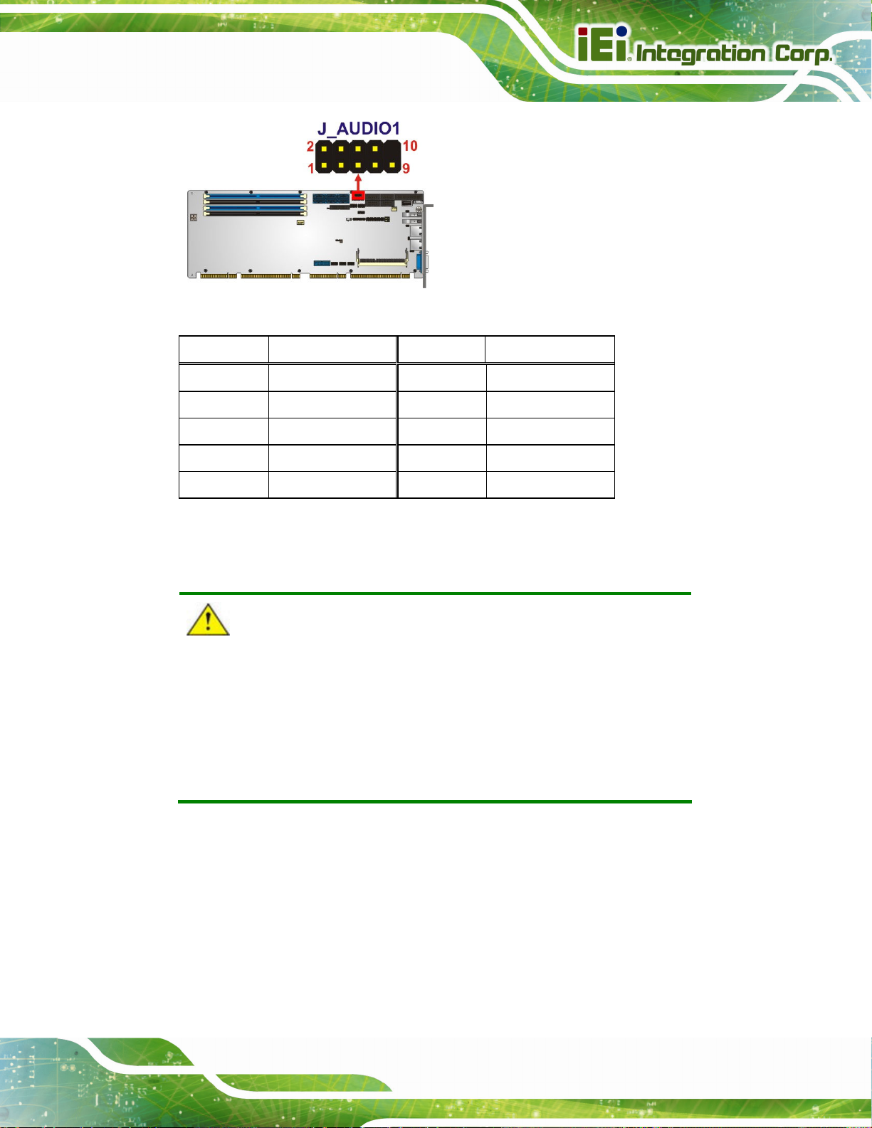
3.2.2 Audio Kit Connector
CN Label: J_AUDIO1
10-pin header, p=2.00 mm
See
See
Page 20
CN Type:
CN Location:
CN Pinouts:
This connector allows connection to an external audio kit.
Figure 3-3
Table 3-4
Page 36
SPCIE-C236 Full-size PICMG 1.3 CPU Card
Figure 3-3: Audio Connector Location
Pin Description Pin Description
1 HDA_SYNC 2 HDA_BIT_CLK
3 HDA_SDOUT 4 HDA_SPKR
5 HDA_SDIN 6 HDA_RST#
7 HDA_VCC 8 HDA_GND
9 HDA_+12V 10 HDA_GND
Table 3-4: Audio Connector Pinouts
3.2.3 Battery Connector
CAUTION:
Risk of explosion if battery is replaced by an incorrect type. Only
certified engineers should replace the on-board battery.
Dispose of used batteries according to instructions and local
regulations.
CN Label: BAT1
CN Type:
CN Location:
2-pin wafer, p=1.25 mm
Figure 3-4
See
Table 3-5
CN Pinouts:
This is connected to the system battery. The battery provides power to the system clock to
retain the time when power is turned off.
See
Page 21
Page 37
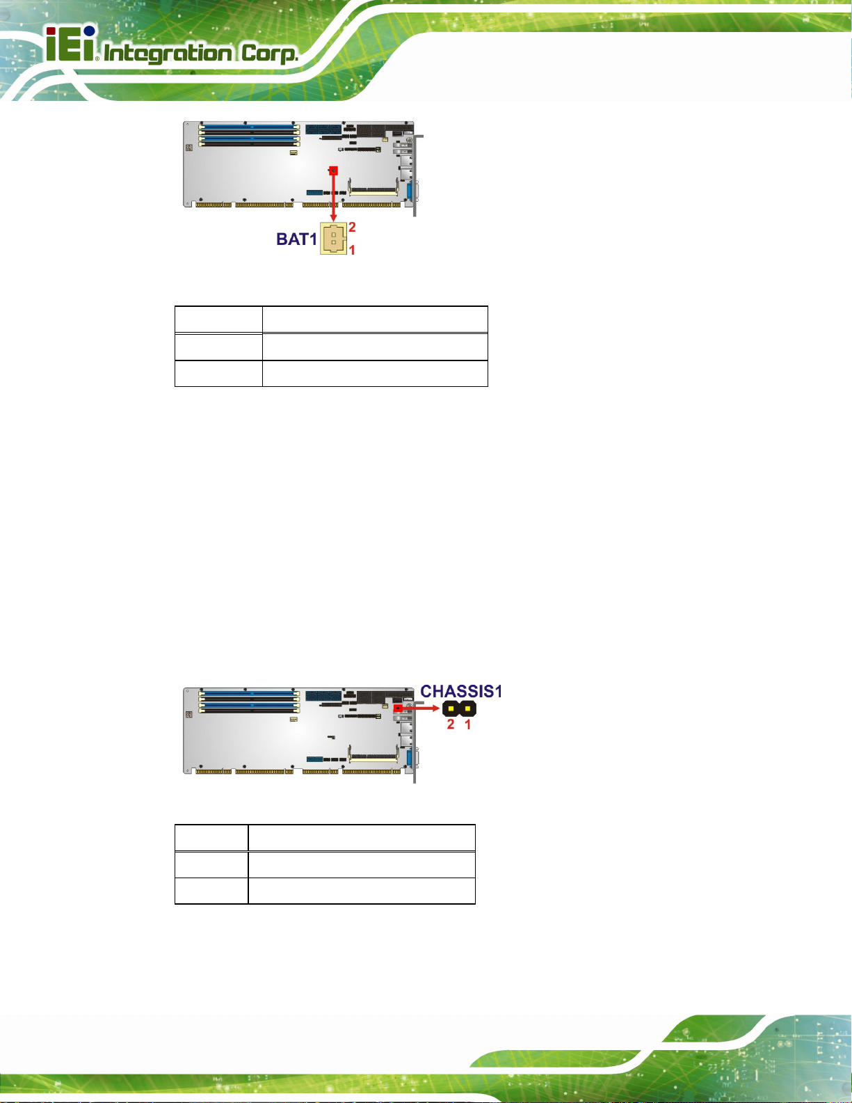
Figure 3-4: Battery Connector Location
Pin Description
1 VBATT
2 GND
Table 3-5: Battery Connector Pinouts
3.2.4 Chassis Intrusion Connector
SPCIE-C236 Full-size PICMG 1.3 CPU Card
CN Label: CHASSIS1
CN Type:
CN Location:
CN Pinouts:
2-pin header, p=2.54 mm
6Figure 3-5
See
Table 3-6
See
The chassis intrusion connector is for a chassis intrusion detection sensor or switch that
detects if a chassis component is removed or replaced.
Figure 3-5: Chassis Intrusion Connector Location
Pin Description
1 +3.3VSB
2 CHASSIS OPEN
Page 22
Table 3-6: Chassis Intrusion Connector Pinouts
Page 38
SPCIE-C236 Full-size PICMG 1.3 CPU Card
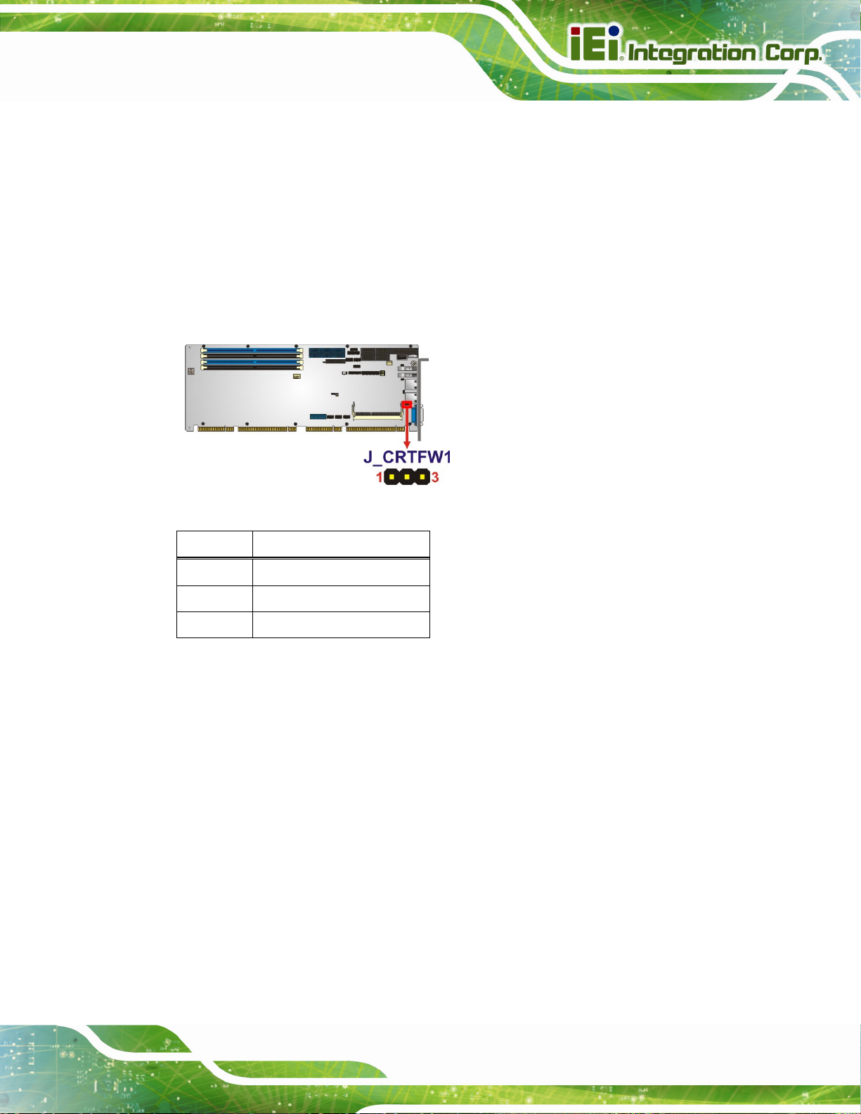
3.2.5 CRT FW Update Connector
CN Label: J_CRTFW1
CN Type:
CN Location:
CN Pinouts:
The CRT FW update connector is used to update the CRT firmware.
Figure 3-6: CRT FW Update Connector Location
3-pin header, p=2.00 mm
See Figure 3-6
See Table 3-7
Pin Description
1 SPC
2 SPD
3 GND
Table 3-7: CRT FW Update Connector Pinouts
3.2.6 DDR4 DIMM Sockets
CN Label: CHA_DIMM0, CHA_DIMM1, CHB_DIMM0, CHB_DIMM1
CN Type:
CN Location:
The DIMM sockets are for DDR4 DIMM memory modules.
288-pin DDR4 DIMM socket
See 6Figure 3-7
Page 23
Page 39

Figure 3-7: DDR4 DIMM Socket Locations
3.2.7 Digital I/O Connector
CN Label: DIO1
SPCIE-C236 Full-size PICMG 1.3 CPU Card
CN Type:
CN Location:
CN Pinouts:
10-pin header, p=2.00 mm
See Figure 3-8
See Table 3-8
The digital I/O connector provides programmable input and output for external devices.
Figure 3-8: Digital I/O Connector Location
Pin Description Pin Description
1 GND 2 VCC
Page 24
3 Output 3 4 Output 2
5 Output 1 6 Output 0
7 Input 3 8 Input 2
9 Input 1 10 Input 0
Table 3-8: Digital I/O Connector Pinouts
Page 40

SPCIE-C236 Full-size PICMG 1.3 CPU Card
3.2.8 EC Debug Connector
CN Label: CN1
CN Type:
CN Location:
CN Pinouts:
18-pin header, p=2.00 mm
Figure 3-9
See
Table 3-9
See
The EC debug connector is used for EC debug.
Figure 3-9: EC Debug Connector Location
Pin Description Pin Description
1 EC_EPP_STB# 2 EC_EPP_AFD#
3 EC_EPP_PD0 4 NC
5 EC_EPP_PD1 6 EC_EPP_INIT#
7 EC_EPP_PD2 8 EC_EPP_SLIN#
9 EC_EPP_PD3 10 GND
11 EC_EPP_PD4 12 NC
13 EC_EPP_PD5 14 EC_EPP_BUSY
15 EC_EPP_PD6 16 EC_EPP_KSI5
17 EC_EPP_PD7 18 EC_EPP_KSI4
Table 3-9: EC Debug Connector Pinouts
Page 25
Page 41

3.2.9 Fan Connector (CPU)
CN Label: CPU_FAN1
SPCIE-C236 Full-size PICMG 1.3 CPU Card
CN Type:
CN Location:
CN Pinouts:
The fan connector attaches to a CPU cooling fan.
Figure 3-10: CPU Fan Connector Location
4-pin wafer, p=2.54 mm
See Figure 3-10
See Table 3-10
Pin Description
1 GND
2 +12V
3 FANIO
4 PWM
Table 3-10: CPU Fan Connector Pinouts
3.2.10 Fan Connectors (System)
CN Label: SYS_FAN1
CN Type:
CN Location:
CN Pinouts:
3-pin wafer, p=2.54 mm
See Figure 3-11
See Table 3-11
Page 26
Page 42

SPCIE-C236 Full-size PICMG 1.3 CPU Card
The fan connector attaches to a system cooling fan.
Figure 3-11: System Fan Connector Location
Pin Description
1 FANIO
2 +12V (PWM)
3 GND
Table 3-11: System Fan (SYS_FAN1) Connector Pinouts
3.2.11 Front Panel Connector
CN Label: F_PANEL1
CN Type:
CN Location:
CN Pinouts:
The front panel connector connects to the indicator LEDs and buttons on the computer's
front panel.
14-pin header, p=2.54 mm
See Figure 3-12
See Table 3-12
Figure 3-12: Front Panel Connector Location
Page 27
Page 43

Function Pin Description Function Pin Description
1 +5V Speaker 2 BEEP_PWR
SPCIE-C236 Full-size PICMG 1.3 CPU Card
Power LED
Power Button
HDD LED
3 NC 4 IPMI ID_LED+
5 GND
7 PWRBTN_SW# Speaker 8 PC_BEEP
9 GND 10 NC
11 +5V 12 EXTRST13 SATA_LED#
Table 3-12: Front Panel Connector Pinouts
3.2.12 I2C Connector
CN Label: I2C1
CN Type:
CN Location:
CN Pinouts:
2
C connector is used to connect I2C-bus devices to the motherboard.
The I
4-pin wafer, p=1.25 mm
Figure 3-13
See
Table 3-13
See
IPMI LED
6 IPMI ID_LED-
Reset
14 GND
Page 28
2
Figure 3-13: I
Pin Description
1 GND
2 I2C_DAT
3 I2C_CLK
4 +5V
C Connector Location
Table 3-13: I2C Connector Pinouts
Page 44

SPCIE-C236 Full-size PICMG 1.3 CPU Card
3.2.13 Internal DisplayPort Connector
CN Label: DP1
CN Type:
CN Location:
CN Pinouts:
20-pin box header, p=2.00 mm
Figure 3-14
See
Table 3-14
See
The DisplayPort connector supports HDMI, LVDS, VGA, DVI and DisplayPort graphics
interfaces with up to 3840x2160 resolutions.
Figure 3-14: Internal DisplayPort Connector Location
Pin Description Pin Description
1 HPD 11 LANE3N
2 AUXP 12 GND
3 GND 13 GND
4 AUXN 14 LANE0P
5 AUX_CTRL_DET_D 15 LANE1P
6 GND 16 LANE0N
7 GND 17 LANE1N
8 LANE2P 18 +3.3V
9 LANE3P 19 +5V
10 LANE2N 20 N/A
Table 3-14: Internal DisplayPort Connector Pinouts
Page 29
Page 45

SPCIE-C236 Full-size PICMG 1.3 CPU Card
3.2.14 iRIS-2400 Module Slot (SPCIE-C236-i2-R10 Only)
CN Label: IPMI1
CN Type:
CN Location:
The iRIS-2400 module slot allows installation of the iRIS-2400 module.
Figure 3-15: iRIS-2400 Module Slot Location
iRIS-2400 module slot
Figure 3-15
See
WARNING:
The iRIS-2400 module slot is designed to install the iRIS-2400 module
only. DO NOT install other modules into the iRIS module slot. Doing so
may cause damage to the SPCIE-C236.
3.2.15 Keyboard and Mouse Connector
CN Label: KB_MS1
CN Type:
CN Location:
CN Pinouts:
The keyboard and mouse connector connects to a PS/2 Y-cable that can be connected to
a PS/2 keyboard and mouse.
6-pin wafer, p=2.00 mm
Figure 3-16
See
Table 3-15
See
Page 30
Page 46

SPCIE-C236 Full-size PICMG 1.3 CPU Card
Figure 3-16: Keyboard and Mouse Connector Location
Pin Description
1 VCC
2 Mouse Data
3 Mouse Clock
4 Keyboard Data
5 Keyboard Clock
6 GND
Table 3-15: Keyboard and Mouse Connector Pinouts
3.2.16 LAN LED Connectors
CN Label: LED_LAN1, LED_LAN2
CN Type:
CN Location:
CN Pinouts:
The LAN LED connectors are used to connect to the LAN LED indicators on th e chassis to
indicate users the link activities of the two LAN ports.
2-pin header, p=2.54 mm
6Figure 3-17
See
6Table 3-16 and Table 3-17
See
Figure 3-17: LAN LED Connector Locations
Page 31
Page 47

Pin Description
1 +3.3V
2 LAN1_LED_LINK#_ACT
Table 3-16: LAN1 LED Connector (LED_LAN1) Pinouts
Pin Description
1 +3.3V
2 LAN2_LED_LINK#_ACT
Table 3-17: LAN2 LED Connector (LED_LAN2) Pinouts
3.2.17 Parallel Port Connector
CN Label: LPT1
SPCIE-C236 Full-size PICMG 1.3 CPU Card
CN Type:
CN Location:
CN Pinouts:
26-pin box header, p=2.54 mm
Figure 3-18
See
Table 3-18
See
The parallel port connector connects to a parallel port connector interface or some other
parallel port device such as a printer.
Figure 3-18: Parallel Port Connector Location
Pin Description Pin Description
Page 32
1 RSTROBE# 2 SIO_AFD#
3 RPD0 4 SIO_ERR#
5 RPD1 6 SIO_INIT#
7 RPD2 8 SIO_SLIN#
9 RPD3 10 GND
Page 48

SPCIE-C236 Full-size PICMG 1.3 CPU Card
11 RPD4 12 GND
13 RPD5 14 GND
15 RPD6 16 GND
17 RPD7 18 GND
19 SIO_ACK# 20 GND
21 SIO_BUSY 22 GND
23 SIO_PE 24 GND
25 SIO_SLCT 26 N/C
Table 3-18: Parallel Port Connector Pinouts
3.2.18 PCIe Mini Slot
CN Label: MPCIE1
CN Type:
CN Location:
CN Pinouts:
PCIe Mini slot
6Figure 3-19
See
Table 3-19
See
The PCIe Mini slot is for installing a full-size/half-size PCIe Mini expansion card, such as
an mSATA SSD or wireless LAN card.
NOTE:
If the user shorts the mSATA setup jumper (MSATA_SW1) to force the
system to enabl e mS ATA devic e or an mSATA device is detec ted, th e
S_ATA6 connector will be disabled. Please refer to Section
detailed information.
4.9.7 for
Figure 3-19: PCIe Mini Slot Location
Page 33
Page 49

Pin Description Pin Description
1 PCIE_WAKE# 2 +3.3V
3 N/C 4 GND
5 N/C 6 1.5V
7 N/C 8 N/C
9 GND 10 N/C
11 MSATA_CLK# 12 N/C
13 MSATA _CLK 14 N/C
15 GND 16 N/C
17 PLTRST_N 18 GND
19 N/C 20 +3.3V
21 GND 22 PLTRST_N
SPCIE-C236 Full-size PICMG 1.3 CPU Card
23
25
27 GND 28 1.5V
29 GND 30 SMB_CLK
31
33
35 GND 36 USB_DATA37 GND 38 USB_DATA+
39 +3.3V 40 GND
41 +3.3V 42 N/C
43 +3.3V 44 N/C
45 CLINK_CLK 46 N/C
47 CLINK_DATA 48 1.5V
49 CLINK_RST# 50 GND
51 MSATA_DET 52 +3.3V
SATA_RX-/PCIE_RXSATA_RX+/PCIE_RX+
SATA_TX-/PCIE_TXSATA_TX+/PCIE_TX+
24 +3.3V
26 GND
32 SMB_DATA
34 GND
Table 3-19: PCIe Mini Slot Pinouts
Page 34
Page 50

SPCIE-C236 Full-size PICMG 1.3 CPU Card
3.2.19 Power Button
CN Label: PWR_SW1
CN Type:
CN Location:
The on-board power button controls system power.
Figure 3-20: Power Button Location
Push button
Figure 3-20
See
3.2.20 RS-232 Serial Port Connectors
CN Label: COM1, COM2
CN Type:
CN Location:
CN Pinouts:
Each of these connectors provides RS-232 connections.
Figure 3-21: RS-232 Serial Port Connector Locations
10-pin box header, p=2.54 mm
See Figure 3-21
See Table 3-20
Page 35
Page 51
Pin Description Pin Description
1 DCD 2 DSR
3 SIN 4 RTS
5 SOUT 6 CTS
7 DTR 8 RI
9 GND 10 GND
SPCIE-C236 Full-size PICMG 1.3 CPU Card
Table 3-20: RS-232 Serial Port Connector Pinouts
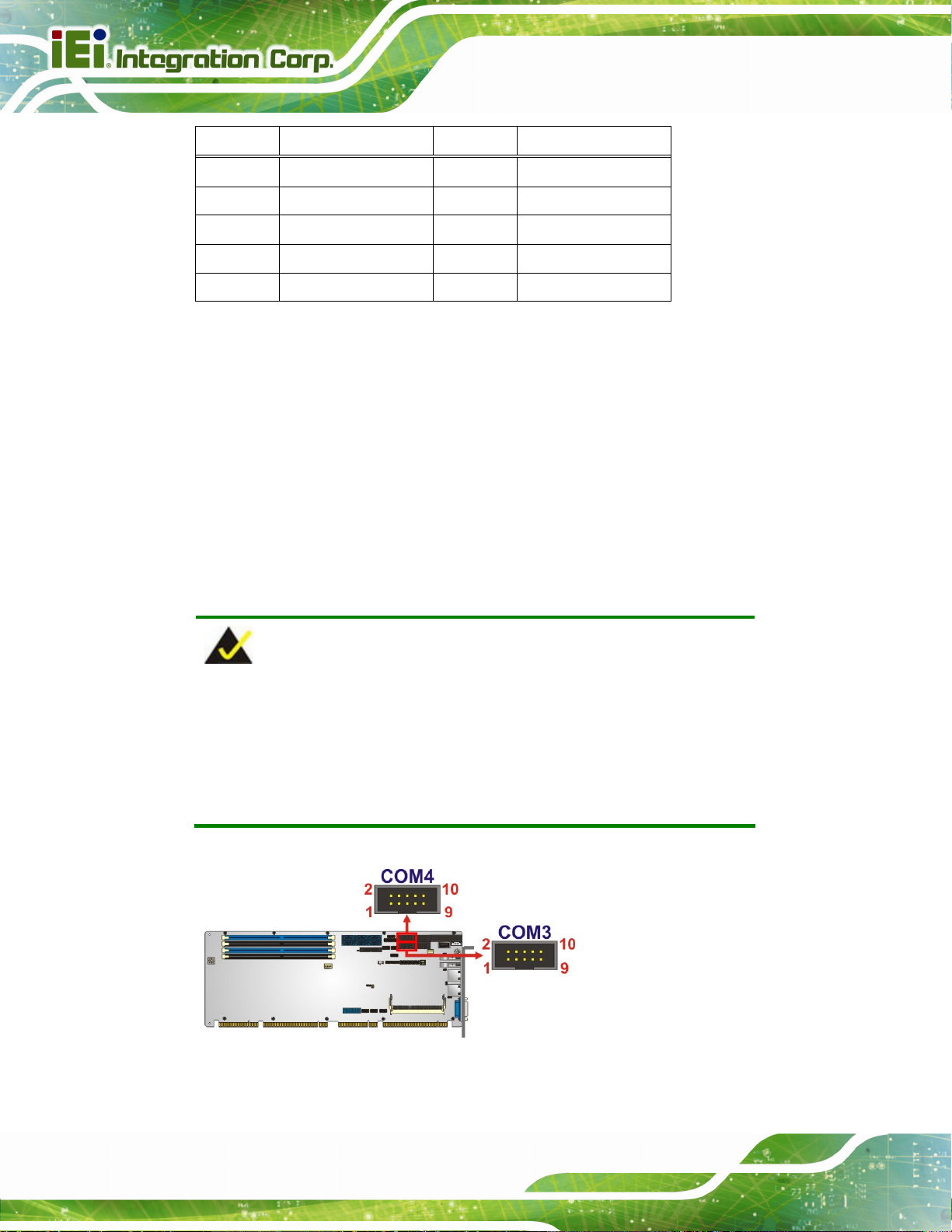
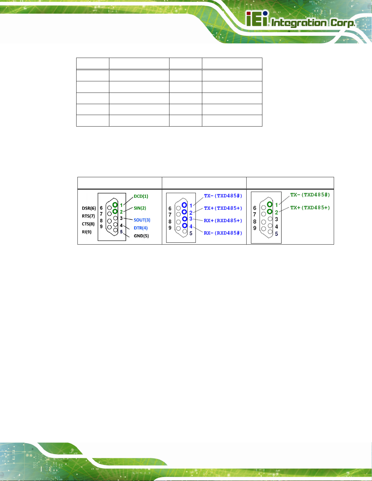
3.2.21 RS-232/422/485 Serial Port Connectors
CN Label: COM3, COM4
CN Type:
CN Location:
CN Pinouts:
10-pin box header, p=2.54 mm
See Figure 3-22
See Table 3-21
Each of these connectors provides RS-232/422/485 connections.
NOTE:
The communication protocol of the serial ports is set through the BIOS menu
in “Advanced Æ Super IO Configuration Æ Serial Port 3/4 Configuration”. Use
the Transfer Mode BIOS option to configure the correspondent serial ports
(refer to Sections
5.3.4.1.3 and 5.3.4. 1.4 for detailed information).
Page 36
Figure 3-22: RS-232/422/485 Serial Port Connector Locations
Page 52
SPCIE-C236 Full-size PICMG 1.3 CPU Card
Pin Description Pin Description
1 DCD 2 DSR
3 SIN 4 RTS
5 SOUT 6 CTS
7 DTR 8 RI
9 GND 10 GND
Table 3-21: RS-232/422/485 Serial Port Connector Pinouts
The user may use the RS-232/422/485 cable to connect to a serial device. The pinouts of
the DB-9 connector are listed below.
RS-232 Pinouts RS-422 Pinouts RS-485 Pinouts
Table 3-22: DB-9 RS-232/422/485 Pinouts
3.2.22 SATA 6Gb/s Drive Connector
CN Label: S_ATA1, S_ATA2, S_ATA3, S_ATA4, S_ATA5, S_ATA6
CN Type:
CN Location:
CN Pinouts:
The SATA drive connectors can be connected to SATA drives and supports up to 6Gb/s
data transfer rate.
7-pin SATA drive connector
Figure 3-23
See
Table 3-23
See
Page 37
Page 53
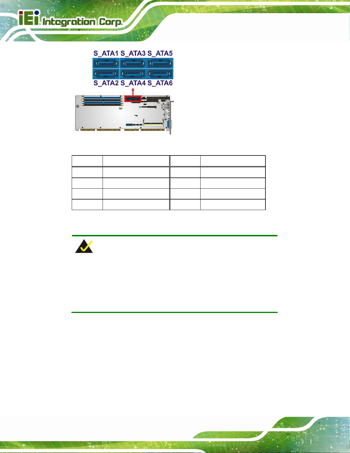
Figure 3-23: SATA 6Gb/s Drive Connector Locations
SPCIE-C236 Full-size PICMG 1.3 CPU Card
Pin Description Pin Description
1 GND 2 TX+
3 TX- 4 GND
5 RX- 6 RX+
7 GND
Table 3-23: SATA 6Gb/s Drive Connector Pinouts
NOTE:
If the user shorts the mSATA setup jumper (MSATA_SW1) to force the
system to enabl e mS ATA devic e or an mSATA device is detec ted, th e
S_ATA6 connector will be disabled. Please refer to Section
detailed information.
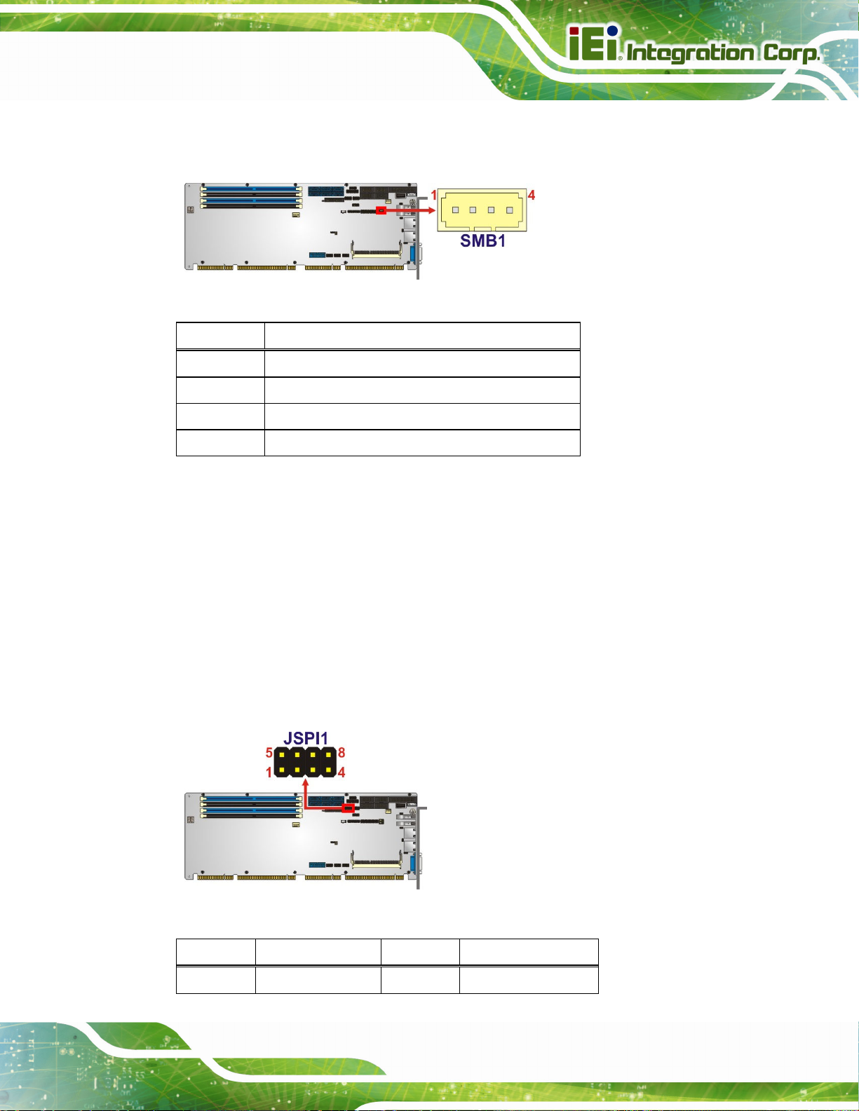
3.2.23 SMBus Connector
CN Label: SMB1
CN Type:
4-pin wafer, p=1.25 mm
4.9.7 for
Page 38
CN Location:
CN Pinouts:
Figure 3-24
See
Table 3-24
See
Page 54
SPCIE-C236 Full-size PICMG 1.3 CPU Card
The SMBus (System Management Bus) connector provides low-speed system
management communications.
Figure 3-24: SMBus Connector Location
Pin Description
1 GND
2 SMB_DATA
3 SMB_CLK
4 +5V
Table 3-24: SMBus Connector Pinouts
3.2.24 SPI Flash Connector
CN Label: JSPI1
CN Type:
CN Location:
CN Pinouts:
8-pin header, p=2.54 mm
See Figure 3-25
See Table 3-25
The SPI flash connector is used to flash the SPI ROM.
Figure 3-25: SPI Flash Connector Location
Pin Description Pin Description
1 +3.3V 2 GND
Page 39
Page 55

Pin Description Pin Description
3 SPI_CS 4 SPI_CLK_SW
5 SPI_SO_SW 6 SPI_SI_SW
7 NC 8 NC
Table 3-25: SPI Flash Connector Pinouts
3.2.25 SPI Flash Connector, EC
CN Label: JSPI2
SPCIE-C236 Full-size PICMG 1.3 CPU Card
CN Type:
CN Location:
CN Pinouts:
8-pin header, p=2.54 mm
See Figure 3-26
See Table 3-26
The SPI flash connector is used to flash the EC ROM.
Figure 3-26: SPI EC Flash Connector Location
Pin Description Pin Description
1 +3.3V 2 GND
Page 40
3 SPI_CS 4 SPI_CLK
5 SPI_SO 6 SPI_SI
7 NC 8 NC
Table 3-26: SPI EC Flash Connector Pinouts
Page 56
SPCIE-C236 Full-size PICMG 1.3 CPU Card
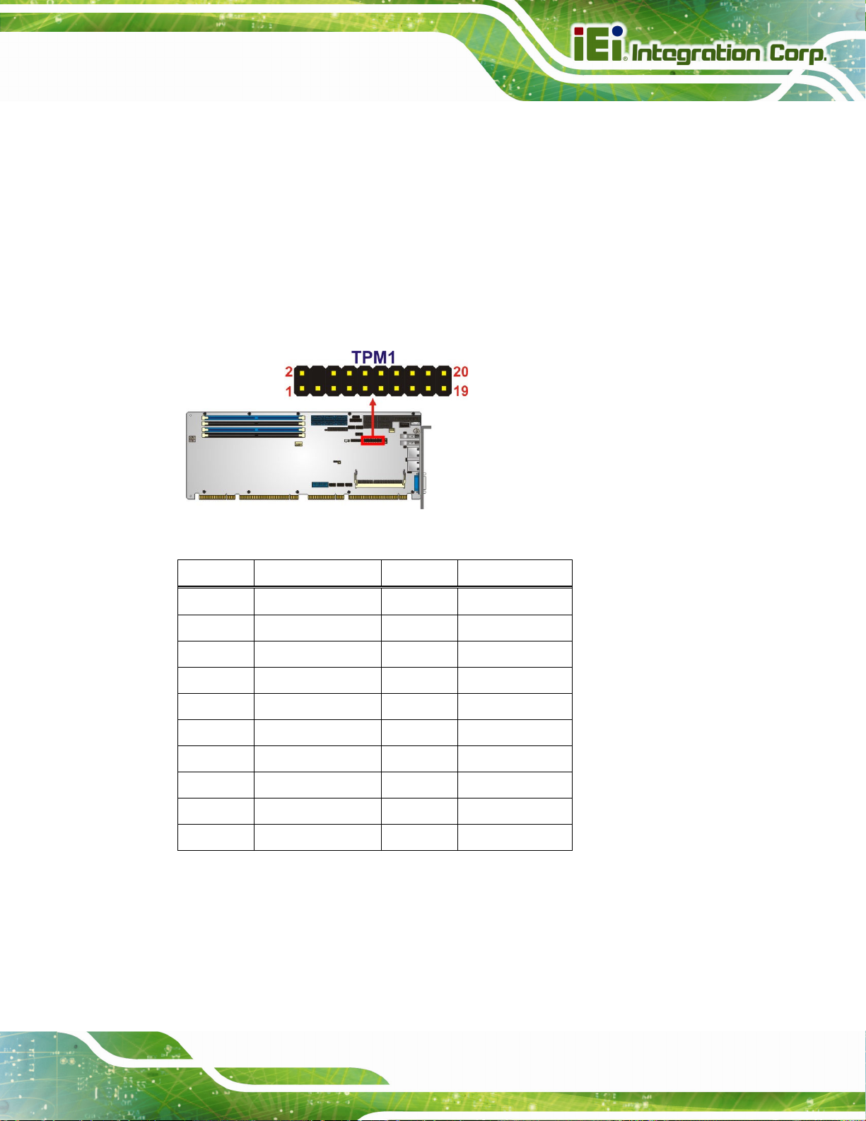
3.2.26 TPM Connector
CN Label: TPM1
CN Type:
CN Location:
CN Pinouts:
20-pin header, p=2.54 mm
See Figure 3-27
See Table 3-27
The TPM connector connects to a TPM module.
Figure 3-27: TPM Connector Location
Pin Description Pin Description
1 LCLK 2 GND
3 LFRAME# 4 KEY
5 LRERST# 6 +5V
7 LAD3 8 LAD2
9 +3.3V 10 LAD1
11 LAD0 12 GND
13 SCL 14 SDA
15 SB3V 16 SERIRQ
17 GND 18 GLKRUN#
19 LPCPD# 20 LDRQ#
Table 3-27: TPM Connector Pinouts
Page 41
Page 57
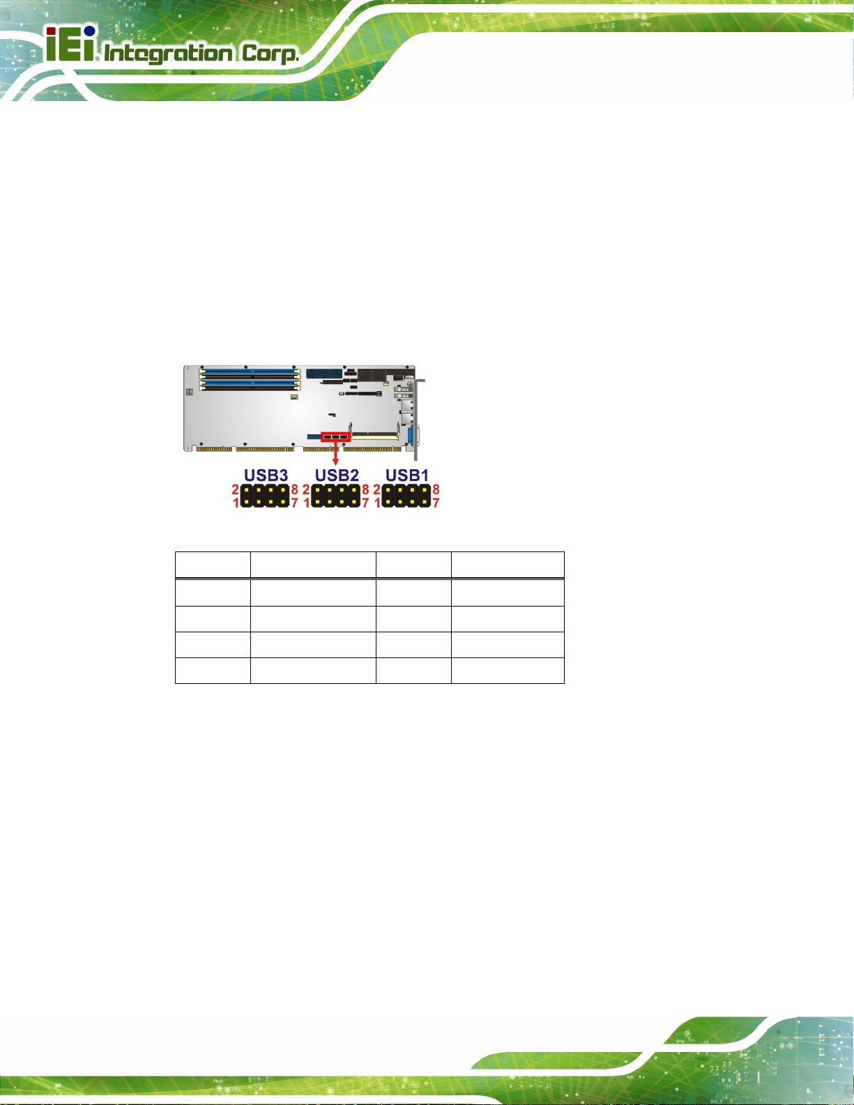
3.2.27 USB 2.0 Connectors
CN Label: USB1, USB2, USB3
SPCIE-C236 Full-size PICMG 1.3 CPU Card
CN Type:
CN Location:
CN Pinouts:
The USB 2.0 connectors connect to USB 2.0 devices. Each pin header provides two USB
2.0 ports.
Figure 3-28: USB 2.0 Connector Locations
8-pin header, p=2.54 mm
See Figure 3-28
See Table 3-28
Pin Description Pin Description
1 VCC 2 GND
3 USB_DATA- 4 USB_DATA+
5 USB_DATA+ 6 USB_DATA7 GND 8 VCC
Table 3-28: USB 2.0 Connector Pinouts
Page 42
Page 58

SPCIE-C236 Full-size PICMG 1.3 CPU Card
3.2.28 USB 2.0 Connector (Type A)
CN Label: USB4
CN Type:
CN Location:
CN Pinouts:
The USB Type A connector connects to a USB 2.0/1.1 device.
Figure 3-29: USB 2.0 Connector (Type A) Pinout Location
USB Type A
See Figure 3-29
See Table 3-29
Pin Description
1 VCC
2 DATA3 DATA+
4 GROUND
Table 3-29: USB 2.0 Connector (Type A) Pinouts
Page 43
Page 59

3.2.29 USB 3.0 Connector
CN Label: USB3_34
SPCIE-C236 Full-size PICMG 1.3 CPU Card
CN Type:
CN Location:
CN Pinouts:
19-pin box header, p=2 mm
See Figure 3-30
See Table 3-30
The USB 3.0 connector connects to USB 3.0 devices. This connector provides two
USB 3.0 ports.
Figure 3-30: USB 3.0 Connector Location
Pin Description Pin Description
1 VCC 11 USB_DATA+
2 USB3_RX- 12 USB_DATA3 USB3_RX+ 13 GND
4 GND 14 USB3_TX+
5 USB3_TX- 15 USB3_TX6 USB3_TX+ 16 GND
7 GND 17 USB3_RX+
8 USB_DATA- 18 USB3_RX9 USB_DATA+ 19 VCC
10 NC
Table 3-30: USB 3.0 Connector Pinouts
Page 44
Page 60

SPCIE-C236 Full-size PICMG 1.3 CPU Card
3.3 External Peripheral Interface Connector Panel
The figure below shows the external peripheral interface connector (EPIC) panel. The
EPIC panel consists of the following:
Figure 3-31: External Peripheral Interface Connector
3.3.1 Ethernet Connectors
CN Label: LAN1, LAN2
CN Type:
CN Location:
CN Pinouts:
Each LAN connector connects to a local network.
Pin Description Pin Description
1 LAN_MDI0P 5 LAN_MDI2P
2 LAN_MDI0N 6 LAN_MDI2N
3 LAN_MDI1P 7 LAN_MDI3P
4 LAN_MDI1N 8 LAN_MDI3N
Table 3-31: LAN Pinouts
RJ-45
See Figure 3-31
See Table 3-31
Figure 3-32: Ethernet Connector
Page 45
Page 61

3.3.2 USB 3.0 Connectors
CN Label: USB3_1, USB3_2
SPCIE-C236 Full-size PICMG 1.3 CPU Card
CN Type:
CN Location:
CN Pinouts:
There are two external USB 3.0 connectors on the SPCIE-C236.
Pin Description Pin Description
1 VBUS 2 D3 D+ 4 GND
5 STDA_SSRX_N 6 STDA_SSRX_P
7 GND_DRAIN 8 STDA_SSTX_N
9 STDA_SSTX_P
Table 3-32: USB 3.0 Port Pinouts
USB 3.0
See Figure 3-31
See Table 3-32
3.3.3 VGA Connector
CN Label: VGA1
Page 46
CN Type:
CN Location:
CN Pinouts:
The 15-pin VGA connector connects to a monitor that accepts a standard VGA input.
15-pin VGA
See Figure 3-31
See Table 3-33
NOTE:
The user has to connect the VGA connector to the monitor before
system booting as the VGA output function is supported via the eDP to
VGA converter.
Page 62

SPCIE-C236 Full-size PICMG 1.3 CPU Card
Pin Description Pin Description
1 RED 2 GREEN
3 BLUE 4 NC
5 GND 6 HOT PLUG DETECT
7 GND 8 GND
9 VCC 10 GND
11 NC 12 DDCDA
13 HSYNC 14 VSYNC
15 DDCCLK
Table 3-33: VGA Connector Pinouts
Figure 3-33: VGA Connector
Page 47
Page 63

SPCIE-C236 Full-size PICMG 1.3 CPU Card
Chapter
4
4 Installation
Page 48
Page 64

SPCIE-C236 Full-size PICMG 1.3 CPU Card
4.1 Anti-static Precautions
WARNING:
Failure to take ESD precautions during the installation of the
SPCIE-C236 may result in permanent damage to the SPCIE-C236 and
severe injury to the user.
Electrostatic discharge (ESD) can cause serious damage to electronic components,
including the SPCIE-C236. Dry climates are especially susceptible to ESD. It is therefore
critical that whenever the SPCIE-C236 or any other electrical component is handled, the
following anti-static precautions are strictly adhered to.
Wear an anti-static wristband: - Wearing a simple anti-static wristband can
help to prevent ESD from damaging the board.
Self-grounding:- Before handling the board touch any grounded conducting
material. During the time the board is handled, frequently touch any
conducting materials that are connected to the ground.
Use an anti-static pad: When configuring the SPCIE-C236, place it on an
anti-static pad. This reduces the possibility of ESD damaging the
SPCIE-C236.
Only handle the edges of the PCB:-: When handling the PCB, hold the PCB
by the edges.
4.2 Installation Considerations
NOTE:
The following installation notices and installation considerations should
be read and understood before installation. All installation notices must
be strictly adhered to. Failing to adhere to these precautions may lead
to severe damage and injury to the person performing the installation.
Page 49
Page 65
SPCIE-C236 Full-size PICMG 1.3 CPU Card
WARNING:
The installation instructions described in this manual should be
carefully followed in order to prevent damage to the components and
injury to the user.
Before and during the installation please DO the following:
Read the user manual:
o The user manual provides a complete description of the SPCIE-C236
installation instructions and configuration options.
Wear an electrostatic discharge cuff (ESD):
o Electronic components are easily damaged by ESD. Wearing an ESD cuff
removes ESD from the body and helps prevent ESD damage.
Place the SPCIE-C236 on an anti-static pad:
o When installing or configuring the motherboard, place it on an anti-static
pad. This helps to prevent potential ESD damage.
Turn all power to the SPCIE-C236 off:
o When working with the SPCIE-C236, make sure that it is disconnected
from all power supplies and that no electricity is being fed into the system.
Before and during the installation of the SPCIE-C236, DO NOT:
Remove any of the stickers on the PCB board. These stickers are required for
warranty validation.
Use the product before verifying all the cables and power connectors are
properly connected.
Allow screws to come in contact with the PCB circuit, connector pins, or its
components.
Page 50
Page 66

SPCIE-C236 Full-size PICMG 1.3 CPU Card
4.3 Socket LGA1151 CPU Installation
WARNING:
CPUs are expensive and sensitive components. When installing the
CPU please be careful not to damage it in anyway. Make sure the CPU
is installed properly and ensure the correct cooling kit is properly
installed.
DO NOT touch the pins at the bottom of the CPU. When handling the
CPU, only hold it on the sides.
To install the CPU, follow the steps below.
Step 1: Disengage the load lever by pressing the lever down and slightly outward to
clear the retention tab. Fully open the lever. See
Figure 4-1: Disengage the CPU Socket Load Lever
Step 2: Open the socket and remove the protective cover. The black protective
Figure 4-1.
cover can be removed by pulling up on the tab labeled "Remove". See
Figure 4-2.
Page 51
Page 67

Figure 4-2: Remove Protective Cover
SPCIE-C236 Full-size PICMG 1.3 CPU Card
Step 3: Inspect the CPU socket. Make sure there are no bent pins and make sure the
socket contacts are free of foreign material. If any debris is found, remove it with
compressed air.
Step 4: Orientate the CPU properly. The contact array should be facing the CPU
socket.
WARNING:
DO NOT touch the pins at the bottom of the CPU. When handling the
CPU, only hold it on the sides.
Step 5: Correctly position the CPU. Match the Pin 1 mark with the cut edge on the
CPU socket.
Step 6: Align the CPU pins. Locate pin 1 and the two orientation notches on the CPU.
Page 52
Carefully match the two orientation notches on the CPU with the socket
alignment keys.
Page 68
SPCIE-C236 Full-size PICMG 1.3 CPU Card
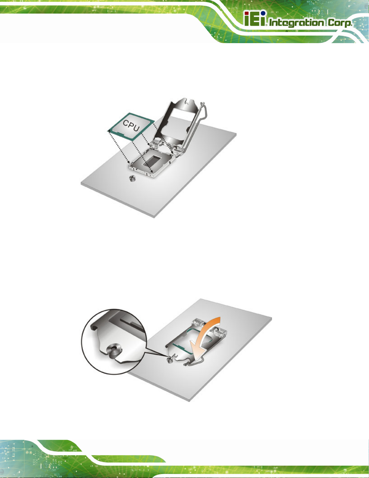
Step 7: Insert the CPU. Gently insert the CPU into the socket. If the CPU pins are
properly aligned, the CPU should slide into the CPU socket smoothly. See
Figure 4-3.
Figure 4-3: Insert the Socket LGA1151 CPU
Step 8: Close the CPU socket. Close the load plate and pull the load lever back a little
to have the load plate be able to secure to the knob. Engage the load lever by
pushing it back to its original position (
resistance, but will not require extreme pressure.
Figure 4-4). There will be some
Figure 4-4: Close the Socket LGA1151
Page 53
Page 69
Step 9: Connect the 12 V power to the board. Connect the 12 V power from the power
supply to the board. Step 0:
SPCIE-C236 Full-size PICMG 1.3 CPU Card
4.4 Socket LGA1151 Cooling Kit Installation
WARNING:
DO NOT attempt to install a push-pin cooling fan.
The pre-installed support bracket prevents the board from
bending and is ONLY compatible with captive screw type cooling
fans.
The cooling kit can be bought from IEI. The cooling kit has a heat sink and fan.
WARNING:
Do not wipe off (accidentally or otherwise) the pre-sprayed layer of
thermal paste on the bottom of the heat sink. The thermal paste
between the CPU and the heat sink is important for optimum heat
dissipation.
To install the cooling kit, follow the instructions below.
Step 1: A cooling kit bra cket is pre-i nstall ed on the rea r of the mother board. See
Figure 4-5.
Page 54
Page 70

SPCIE-C236 Full-size PICMG 1.3 CPU Card
Figure 4-5: Cooling Kit Support Bracket
Step 2: Place the cooling kit onto the socket LGA1151 CPU. Make sure the CPU
cable can be properly routed when the cooling kit is installed.
Step 3: Mount the cooling kit. Gently place the cooling kit on top of the CPU. Make
sure the four threaded screws on the corners of the cooling kit properly pass
through the holes of the cooling kit bracket.
Step 4: Tighten the screws. Use a screwdriver to tighten the four screws. In a diagonal
pattern, tighten each screw a few turns then move to the next one, until they are
all secured. Do not overtighten the screws.
Step 5: Connect the fan cable. Connect the cooling kit fan cable to the CPU fan
connector on the SPCIE-C236. Carefully route the cable and avoid heat
generating chips and fan blades.Step 0:
Page 55
Page 71
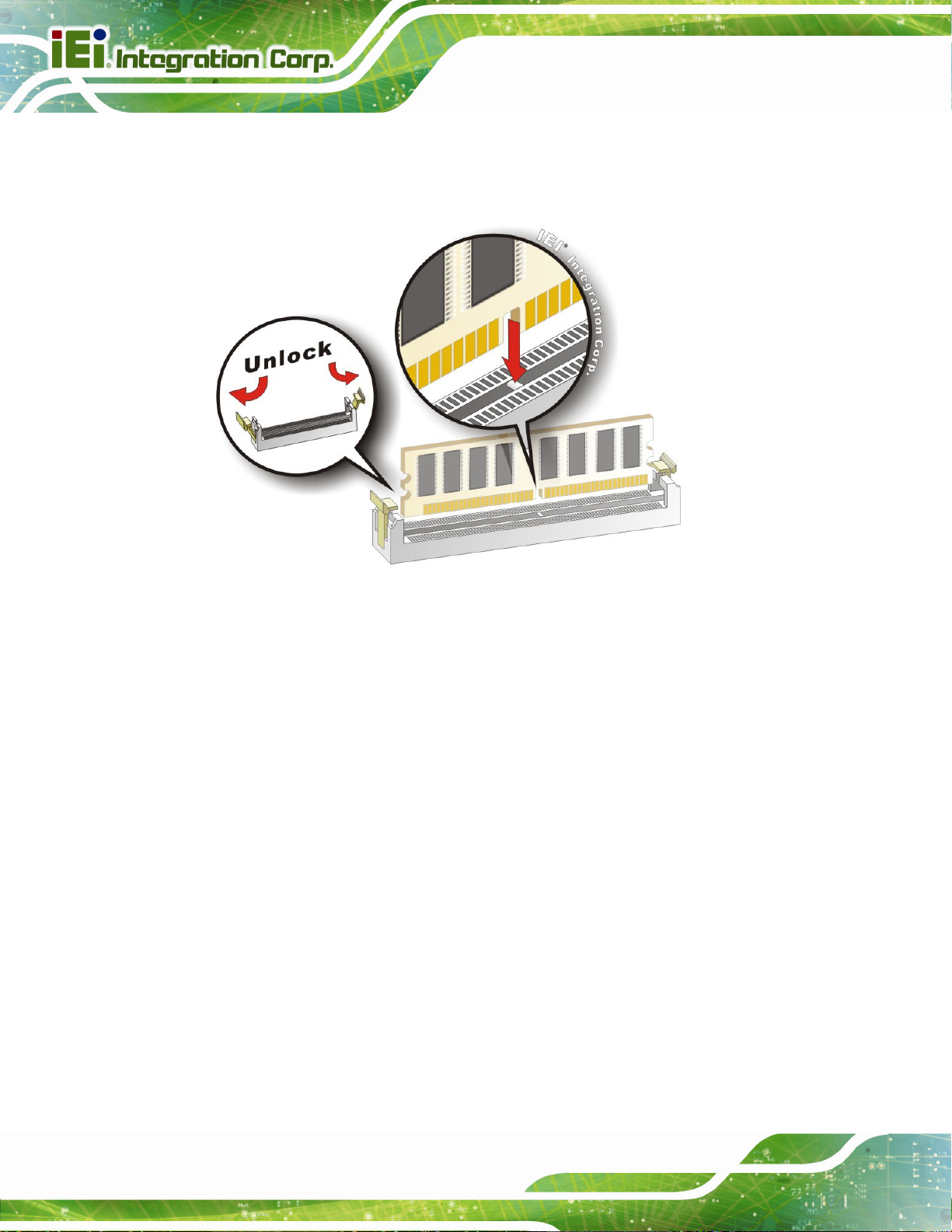
4.5 DIMM Installation
To install a DIMM, please follow the steps below and refer to Figure 4-6.
SPCIE-C236 Full-size PICMG 1.3 CPU Card
Figure 4-6: DIMM Installation
Step 1: Open the DIMM socket handles. Open the two handles outwards as far as
they can. See
Step 2: Align the DIMM with the socket. Align the DIMM so the notch on the memory
lines up with the notch on the memory socket. See
Step 3: Insert the DIMM. Once aligned, press down until the DIMM is properly seated.
Clip the two handles into place. See
Step 4: Removing a DIMM. To remove a DIMM, push both handles outward. The
memory module is ejected by a mechanism in the socket.Step 0:
Figure 4-6.
Figure 4-6.
Figure 4-6.
Page 56
Page 72
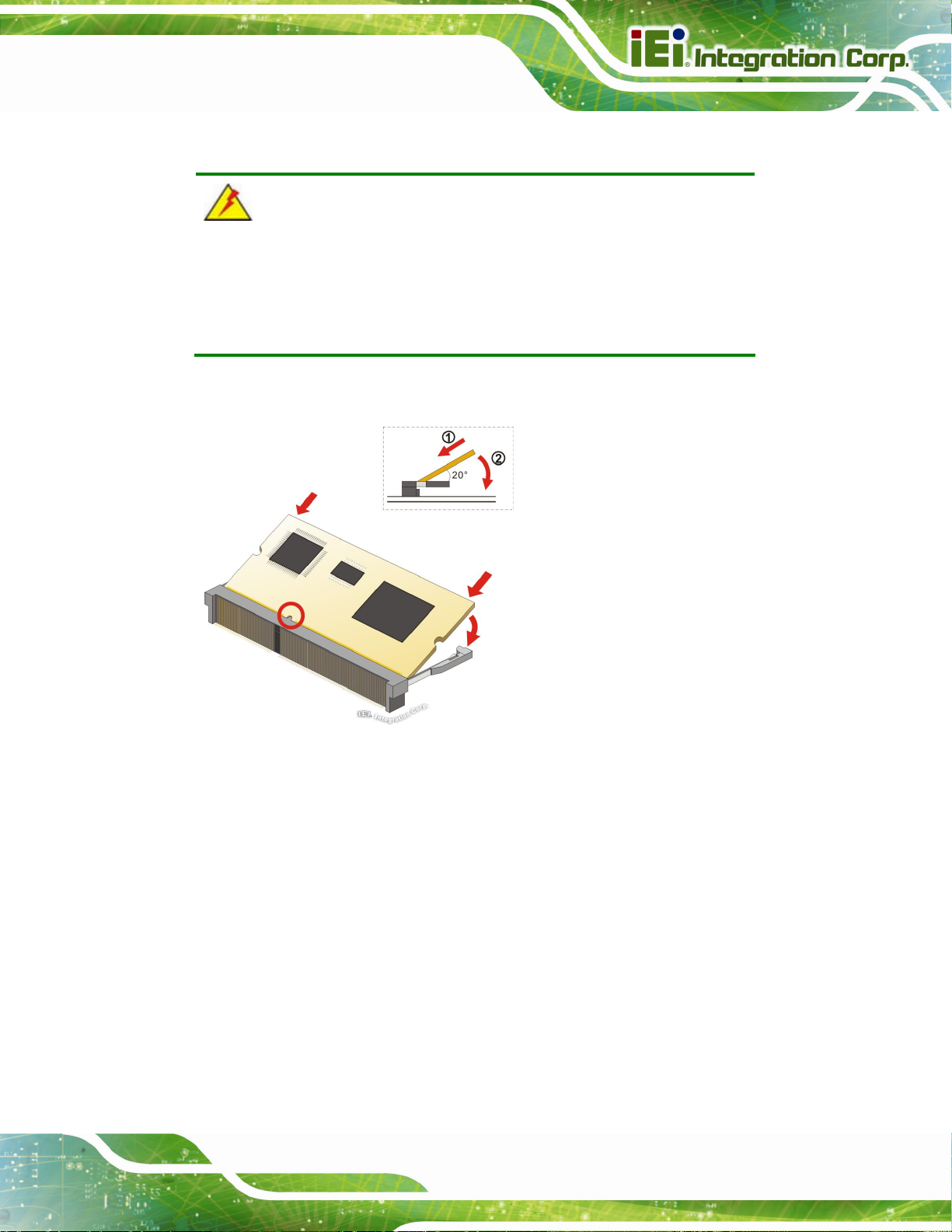
SPCIE-C236 Full-size PICMG 1.3 CPU Card
4.6 iRIS-2400 Module Installation (Optional)
WARNING:
The iRIS-2400 module slot is designed to install the I E I iRIS-2400 IPMI
2.0 module only. DO NOT install other modules into the iRIS module
slot. Doing so may cause damage to the SPCIE-C236.
To install the iRIS-2400 module, please follow the steps below and refer to Figure 4-7.
Figure 4-7: iRIS-2400 Module Installation
Step 1: Locate the IPMI module slot. Place the SPCIE-C236 on an anti-static pad.
Step 2: Align the iRIS-2400 module with the iRIS module slot. Align the notch on the
module with the notch on the iRIS module slot.
Step 3: Insert the iRIS-2400 module. Push the module in at a 20º angle (
Step 4: Seat the iRIS-2400 module. Gently push downwards and the arms clip into
place (
Figure 4-7). Step 0:
Figure 4-7).
Page 57
Page 73
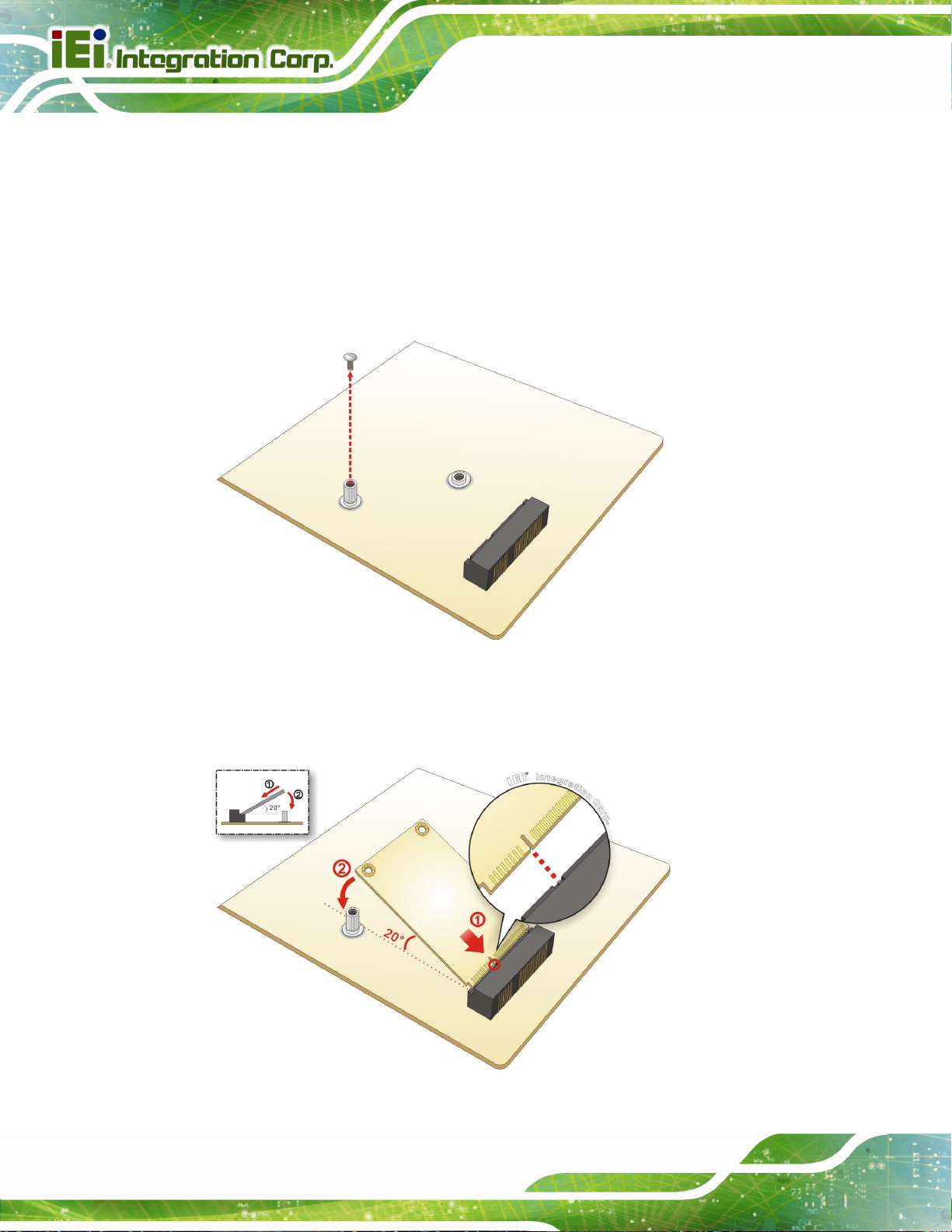
SPCIE-C236 Full-size PICMG 1.3 CPU Card
4.7 Full-size PCIe Mini Card Installation
The PCIe Mini card slot allows installation of either a full-size or half-size PCIe Mini card.
To install a full-size PCIe Mini card, please follow the steps below.
Step 1: Locate the PCIe Mini card slot. See Chapter 3.
Step 2: Remove the retention scr ew. Remove the retention screw as shown in
Figure 4-8.
Figure 4-8: Removing the Retention Screw
Step 3: Insert into the socket at an angle. Line up the notch on the card with the notch on
the slot. Slide the PCIe Mini card into the socket at an angle of about 20º (
Figure 4-9).
Page 58
Figure 4-9: Inserting the Full-size PCIe Mini Card into the Slot at an Angle
Page 74

SPCIE-C236 Full-size PICMG 1.3 CPU Card
Step 4: Secure the full-size PCIe Mini card. Secure the full-size PCIe Mini card with
the retention screw previously removed (
Figure 4-10: Securing the Full-size PCIe Mini Card
4.8 Half-size PCIe Mini Card Installation
Figure 4-10). Step 0:
The PCIe Mini card slot allows installation of either a full-size or half-size PCIe Mini card.
To install a half-size PCIe Mini card, please follow the steps below.
Step 1: Locate the PCIe Mini card slot. See Chapter 3.
Step 2: Install the standoff to the screw hole for the half-size PCIe Mini card. Install
the supplied standoff to the screw hole for the half-size PCIe Mini card
Figure 4-11).
(
Page 59
Page 75

Figure 4-11: Installing the Standoff
Step 3: Insert into the socket at an angle. Line up the notch on the card with the notch on
SPCIE-C236 Full-size PICMG 1.3 CPU Card
the slot. Slide the PCIe Mini card into the sl ot at an angle of about 20º (
Figure 4-12: Inserting the Half-size PCIe Mini Card into the Slot at an Angle
Step 4: Secure the half-size PCIe Mini card. Secure the half-size PCIe Mini card with
the supplied retention screw (
Figure 4-13). Step 0:
Figure 4-12).
Page 60
Page 76

SPCIE-C236 Full-size PICMG 1.3 CPU Card
Figure 4-13: Securing the Half-size PCIe Mini Card
4.9 System Configuration
The system configuration should be performed before installation.
4.9.1 AT/ATX Power Mode Setting
The AT and ATX power mode selection is made through the AT/ATX power mode switch
which is shown in
Figure 4-14: AT/ATX Power Mode Switch Location
Figure 4-14.
Setting Description
1-2 (down) ATX power mode (default)
2-3 (up) AT power mode
Table 4-1: AT/ATX Power Mode Switch Settings
Page 61
Page 77

4.9.2 Clear CMOS Button
To reset the BIOS, remove the on-board battery and press the clear CMOS button for
SPCIE-C236 Full-size PICMG 1.3 CPU Card
three seconds or more. The clear CMOS button location is shown in
Figure 4-15: Clear CMOS Button Location
4.9.3 PCIe x4 Channel Mode Setup
The user can select to use either one PCIe x4 slot or four PCIe x1 slots on the backplane
via the BIOS switch. Refer to below table for the BIOS switch settings.
Setting Description
1-2 (BIOS1) Sets the PCIe x4 link width as four PCIe x1 slots (default)
Figure 4-15.
2-3 (BIOS2) Sets the PCIe x4 link width as one PCIe x4 slot
Table 4-2: BIOS Switch Settings
Figure 4-16: BIOS Switch Location
Page 62
Page 78

SPCIE-C236 Full-size PICMG 1.3 CPU Card
To switch BIOS1 to BIOS2 or BIOS2 to BIOS1 successfully, please follow the steps below.
Step 1: Unplug the system power cord.
Step 2: Switch BIOS1 to BIOS2 or BIOS2 to BIOS1 by moving the BIOS switch to
BIOS1 or BIOS2 position as shown in
Step 3: Remove the on-board battery, and then reinstall it.
Step 4: Clear CMOS by pressing the clear CMOS button for three seconds or more.
Step 5: Perform the system booting. Step 0:
NOTE:
The user can check which BIOS is being used from the BIOS Number
item in the Main BIOS menu (
4.9.4 PCIe x16 Channel Mode Setup
The SPCIE-C236 supports one PCIe x16 interface on the backplane. The PCIe x16
channel mode setup is made through the BIOS menu in “Chipset Æ System Agent (SA)
Configuration Æ PEG Port Configuration”. Use the PEG Link Width Configuration BIOS
Figure 4-16.
BIOS Menu 1).
option to configure the PCIe x16 channel mode.
Options Description
1x16 Sets the PCIe x16 link width as one PCIe x16 slot (default)
2x8 Sets the PCIe x16 link width as two PCIe x8 slots
1x8, 2x4 Sets the PCIe x16 link width as one PCIe x8 and two PCIe x4
Table 4-3: PCIe x16 Channel Mode Setup
Please refer to Section 5.4.1.2 for detailed information.
Page 63
Page 79

SPCIE-C236 Full-size PICMG 1.3 CPU Card
4.9.5 Flash Descriptor Security Override Jumper
The flash descriptor security override jumper (J_FLASH2) allows to enable or disable the
ME firmware update. Refer to
settings.
Setting Description
Short 1-2 Disabled (default)
Short 2-3 Enabled
Table 4-4: Flash Descriptor Security Override Jumper Settings
Table 4-4 and Figure 4-17 for the jumper location and
Figure 4-17: Flash Descriptor Security Override Jumper Location
To update the ME firmware, please follow the steps below.
Step 1: Before turning on the system power, short pin 2-3 of the flash descriptor security
override jumper.
Step 2: Update the BIOS and ME firmware, and then turn off the system power.
Step 3: Remove the metal clip on the flash descriptor security override jumper or return
to its default setting (short pin 1-2).
Step 4: Restart the system. The system will reboot 2 ~ 3 times to complete the ME
firmware update.Step 0:
Page 64
Page 80
SPCIE-C236 Full-size PICMG 1.3 CPU Card
4.9.6 USB Power Selection
The USB power selection is made through the BIOS menu in “Chipset Æ PCH-IO
Configuration”. Use the USB Power SW1 and the USB Power SW2 BIOS options to
configure the correspondent USB ports (see
Table 4-5) and refer to Table 4-6 to select
the USB power source.
BIOS Options Configured USB Ports
USB3_1 (external USB 3.0 port)
USB Power SW1
USB Power SW2
USB3_2 (external USB 3.0 port)
USB4 (internal USB 2.0 port, Type A)
USB1 (internal USB 2.0 ports)
USB2 (internal USB 2.0 ports)
USB3 (internal USB 2.0 ports)
USB3_34 (internal USB 3.0 ports)
Table 4-5: BIOS Options and Configured USB Ports
Options Description
+5V DUAL +5V dual (default)
+5V +5V
Table 4-6: USB Power Source Setup
Please refer to Section 5.4.2 for BIOS setup.
Page 65
Page 81

4.9.7 mSATA Setup
The mSATA setup jumper specifies whether to automatically detect the mSATA device
installed in the PCIe Mini slot (MPCIE1). If the user shorts the mSATA setup jumper to
force the system to enable mSATA device, the S_ATA6 connector will be disabled.
Setting Description
Open Automa tical ly dete ct mSATA device (default)
SPCIE-C236 Full-size PICMG 1.3 CPU Card
Short 1-2
Table 4-7: mSATA Setup Jumper Settings
Force to enable mSATA devic e
(The S_ATA6 connector will be disabled)
Figure 4-18: mSATA Setup Jumper Location
4.10 Internal Peripheral Device Connections
This section outlines the installation of peripheral devices to the onboard connectors.
4.10.1 SATA Drive Connection
Page 66
The SPCIE-C236 is shipped with two SATA drive cables. To connect the SATA drives to
the connectors, please follow the steps below.
Step 1: Locate the connectors. The locations of the SATA drive connectors are shown
in Chapter 3.
Step 2: Insert the cable connector. Insert the cable connector into the on-board SATA
drive connector until it clips into place. See
Figure 4-19.
Page 82
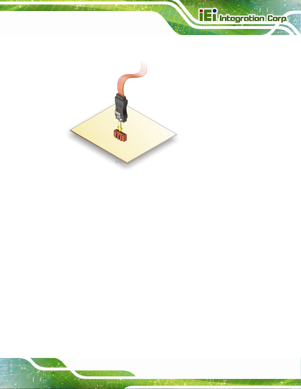
SPCIE-C236 Full-size PICMG 1.3 CPU Card
Figure 4-19: SATA Drive Cable Connection
Step 3: Connect the cable to the SATA disk. Connect the connector on the other end
of the cable to the connector at the back of the SATA drive. See
Step 4: Connect the SATA power cable. Connect the SATA power connector to the
back of the SATA drive. See
Figure 4-20. Step 0:
Figure 4-20.
Page 67
Page 83
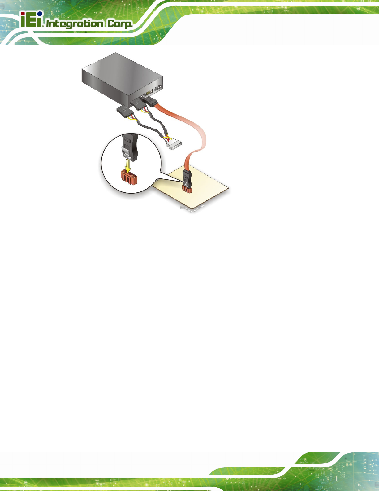
SPCIE-C236 Full-size PICMG 1.3 CPU Card
Figure 4-20: SATA Power Drive Connection
The SATA power cable can be bought from IEI. See
Optional Items in Section 2.4.
4.11 Adding USB 3.0 Drivers to a Windows 7 Installation Image
The Windows 7 installation media does not include native driver support for USB 3.0. In
order to use the USB keyboard or mouse connected to a USB 3.0 port during OS
installation, the user has to update the Windows 7 installation image so that it contains
USB 3.0 drivers. Please follow the instructions below to complete the task.
Step 1: Prepare a USB flash drive installer.
On a working computer, use your Windows 7 DVD or ISO image to create a
bootable USB flash drive.
Step 2: Download the Windows 7 USB 3.0 Creator Utility from:
https://downloadcenter.intel.com/download/25476/Windows-7-USB-3-0-Creator-
Page 68
Utility.
Page 84
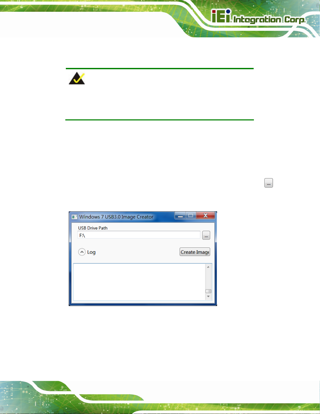
SPCIE-C236 Full-size PICMG 1.3 CPU Card
Step 3: Extract the downloaded file to a temporary folder on a computer where the user
has logged in as the administrator.
NOTE:
The OS version of the computer can be Windows 7, Windows 8.1 or
Windows 10.
Step 4: Connect the USB drive containing the Windows 7 installation image to the
computer.
Step 5: Right click on Installer_Creator.exe from the extracted files and select Run as
administrator.
Step 6: The Windows 7 USB 3.0 Creator Utility screen appears (
to browse to the root of the USB drive containing the Windows 7 image.
Figure 4-21: Windows 7 USB 3.0 Creator Utility
Step 7: Click Create Image to start the update process.
Figure 4-21). Click
Page 69
Page 85
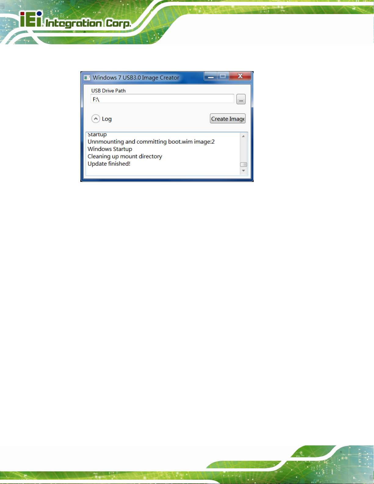
Step 8: Wait for the process to finish. It may take up to 15 minutes.
Figure 4-22: Update Process is Complete
SPCIE-C236 Full-size PICMG 1.3 CPU Card
Step 9: Now the user can proceed with the Windows 7 installation using the updated
installer. Step 0:
4.12 Intel® AMT Setup Procedure
The SPCIE-C236 is featured with the Intel® Active Management Technology (AMT). To
enable the Intel® AMT function, follow the steps below.
Step 1: Make sure at least one of the memory sockets is installed with a DDR4 DIMM.
Step 2: Connect an Ethernet cable to the RJ-45 connector labeled LAN1.
Step 3: The AMI BIOS options regarding the Intel® ME or Intel® AMT must be enabled,
Step 4: Properly install the Intel® Management Engine Components drivers from the
iAMT Driver & Utility directory in the driver CD.
Step 5: Configure the Intel® Management Engine BIOS extension (MEBx). To get into
the Intel® MEBx settings, press <Ctrl+P> after a single beep during boot-up
Page 70
process. Enter the Intel® current ME password as it requires (the Intel® default
password is admin). Step 0:
Page 86
SPCIE-C236 Full-size PICMG 1.3 CPU Card
NOTE:
To change the password, enter a new password following the strong
password rule (containing at least one upper case letter, one lower
case letter, one digit and one special character, and be at least eight
characters).
4.13 IPMI Setup Procedure (SPCIE-C236-i2-R10 Only)
The SPCIE-C236-i2 features Intelligent Platform Management Interface (IPMI) that helps
lower the overall costs of server management by enabling users to maximize IT resources,
save time and manage multiple systems. The SPCIE-C236-i2 supports IPMI 2.0 through
the optional iRIS-2400 module. Follow the steps below to setup IPMI.
4.13.1 Managed System Hardware Setup
The hardware configuration of the managed system (SPCIE-C236-i2) is described below.
Step 1: Install an iRIS-2400 module to the IPMI module socket (refer to Section
Step 2: Make sure at least one DDR4 DIMM is installed in one of the DIMM sockets. If
multiple DIMMs are installed, all of the DIMMs must be same size, same speed
and same brand to get the best performance.
Step 3: Connect an Ethernet cable to the RJ-45 connector labeled LAN2 (
Figure 3-31).
4.13.2 Using the IEI iMAN Web GUI
To manage a client system from a remote console using IEI iMAN Web GUI, follow the
steps below.
Step 1: Obtain the IP address of the managed system. It is recommended to use the
4.6).
IPMI Tool on the managed system to obtain the IP address. To use IPMI Tool to
obtain IP address, follow the steps bel ow:
Page 71
Page 87
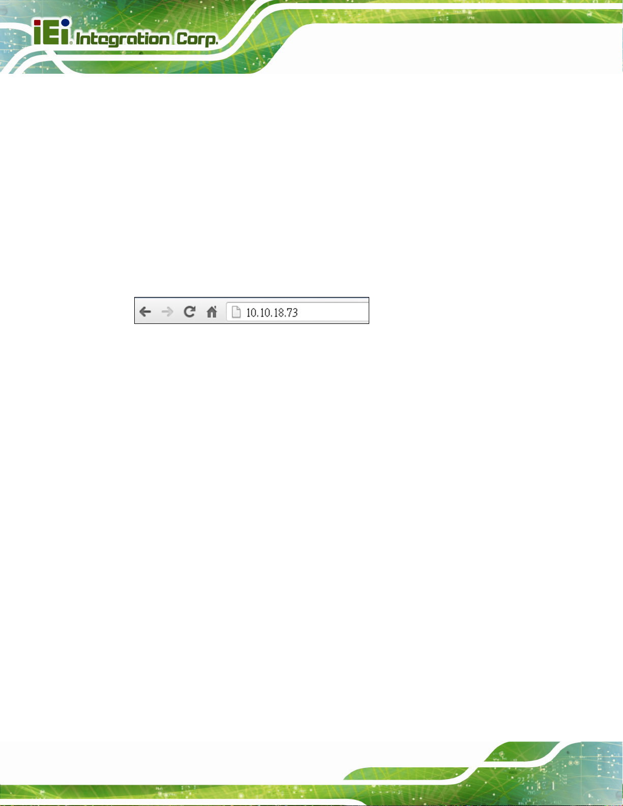
a. Copy the Ipmitool.exe file to a bootable USB flash drive.
b. Insert the USB flash drive to the SPCIE-C236-i2
c. The SPCIE-C236-i2 boots from the USB flash drive
d. Enter the following command: ipmitool 20 30 02 01 03 00 00
(there is a space between each two -digit number)
e. A serial of number shows. The last four two-digit hexadecimal numbers are
the IP address. Convert the hexadecimal numbers to decimal numbers.
Step 2: On the remote management console, open a web browser. Enter the managed
SPCIE-C236 Full-size PICMG 1.3 CPU Card
system IP address in the web browser (
Figure 4-23: IEI iMAN Web Address
Step 3: The login page appears in the web browser.
Step 4: Enter the user name and password to login the system. The default login
username and password are:
-Username: admin
-Password: admin
Step 5: Press the login button to login the system.
Step 6: The IEI iMAN Web Interface appears. Step 0:
Figure 4-23).
Page 72
Page 88
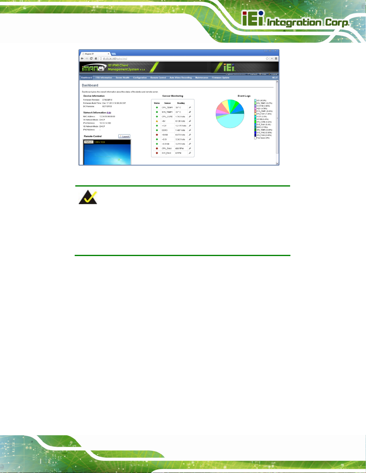
SPCIE-C236 Full-size PICMG 1.3 CPU Card
Figure 4-24: IEI iMAN Web GUI
NOTE:
To understand how to use the IEI iMAN Web GUI, please refer to the
iRIS-2400 Web GUI user manual in the utility CD came with the
SPCIE-C236. The user manual describes each function in detail.
Page 73
Page 89

SPCIE-C236 Full-size PICMG 1.3 CPU Card
Chapter
5
5 BIOS
Page 74
Page 90

SPCIE-C236 Full-size PICMG 1.3 CPU Card
5.1 Introduction
The BIOS is programmed onto the BIOS chip. The BIOS setup program allows changes to
certain system settings. This chapter outlines the options that can be changed.
NOTE:
Some of the BIOS options may vary throughout the life cycle of the
product and are subject to change without prior notice.
5.1.1 Starting Setup
The UEFI BIOS is activated when the computer is turned on. The setup program can be
activated in one of two ways.
1. Press the DEL or F2 key as soon as the system is turned on or
2. Press the DEL or F2 key when the “Press DEL or F2 to enter SETUP”
message appears on the screen.
If the message disappears before the DEL or F2 key is pressed, restart the computer and
try again.
5.1.2 Using Setup
Use the arrow keys to highlight items, press ENTER to select, use the PageUp and
PageDown keys to change entries, press F1 for help and press E
keys are shown in the following table.
Key Function
Up arrow Move to previous item
Down arrow Move to next item
Left arrow Move to the item on the left hand side
Right arrow Move to the item on the right hand side
+ Increase the numeric value or make changes
SC to quit. Navigation
- Decrease the numeric value or make changes
Page Up Move to the previous page
Page Dn Move to the next page
Page 75
Page 91

Key Function
Esc Main Menu – Quit and not save changes into CMOS
F1 General help, only for Status Page Setup Menu and Option Page
F2 Load previous values
F3 Load optimized defaults
F4 Save changes and Exit BIOS
Table 5-1: BIOS Navigation Keys
5.1.3 Getting Help
When F1 is pressed, a small help window describing the appropriate keys to use and the
SPCIE-C236 Full-size PICMG 1.3 CPU Card
Status Page Setup Menu and Option Page Setup Menu -- Exit
current page and return to Main Menu
Setup Menu
possible selections for the highlighted item appears. To exit the Help Window, press E
5.1.4 Unable to Reboot after Configuration Changes
If the computer cannot boot after changes to the system configuration is made, CMOS
defaults. Use the clear CMOS button described in Chapter 4.
5.1.5 BIOS Menu Bar
The menu bar on top of the BIOS screen has the following main items:
Main – Changes the basic system configuration.
Advanced – Changes the advanced system settings.
Chipset – Changes the chipset settings.
Security – Sets User and Supervisor Passwords.
Boot – Changes the system boot configuration.
Save & Exit – Selects exit options and loads default settings
Server Mgmt – Configures system event log and BMC network parameters
The following sections completely describe the configuration options found in the menu
items at the top of the BIOS screen and listed above.
SC.
5.2 Main
The Main BIOS menu (BIOS Menu 1) appears when the BIOS Setup program is entered.
The Main menu gives an overview of the basic system information.
Page 76
Page 92

SPCIE-C236 Full-size PICMG 1.3 CPU Card
Aptio Setup Utility – Copyright (C) 2016 American Megatrends, Inc.
Main Advanced Chipset Security Boot Save & Exit Server Mgmt
BIOS Information
BIOS Vendor American Megatrends
Core Version 5.11
Compliancy UEFI 2.4; PI 1.3
Project Version B397AR11.ROM
Build Date and Time 06/17/2016 16:20:22
BIOS Number BIOS No.1
iWDD Vendor iEi
iWDD Version B397ET10.bin
IPMI Module N/A
Processor Information
Name SkyLake DT
Brand String Intel(R) Xeon(R) CPU
E3-1268L v5 @ 2.40GHz
Frequency 2400 MHz
Processor ID 506E3
Stepping R0/S0/N0
Number of Processors 4Core(s) / 8Thread(s)
Microcode Revision 7C
GT Info GT2
Memory RC Version 1.8.0.1
Total Memory 8192 MB
Set the Date. Use Tab to
switch between Date
elements.
----------------------
ÆÅ
: Select Screen
↑ ↓: Select Item
Enter: Select
+/-: Change Opt.
F1: General Help
F2: Previous Values
F3: Optimized Defaults
F4: Save & Exit
ESC: Exit
Memory Frequency 2133 MHz
PCH Information
Name SKL PCH-H
PCH SKU Server SKU Intel C236
Stepping 31/D1
LAN PHY Revision B2
ME FW Version 11.0.0.1194
ME Firmware SKU Corporate SKU
SPI Clock Frequency
DOFR Support Unsupported
Read Status Clock Frequnecy 17 MHz
Write Status Clock Frequnecy 48 MHz
Fast Read Status Clock Frequnecy 48 MHz
Access Level Administrator
System Date [Thu 09/22/2016]
System Time [15:10:27]
Version 2.17.1255. Copyright (C) 2016 American Megatrends, Inc.
BIOS Menu 1: Main
Page 77
Page 93

The Main menu has two user configurable fields:
Î Sy stem Date [xx/xx/xx]
Use the System Date option to set the system date. Manually enter the day, month and
year.
Î Sy stem Time [xx:xx:xx]
Use the System Time option to set the system time. Manually enter the hours, minutes
and seconds.
5.3 Advanced
Use the Advanced menu (BIOS Menu 2) to configure the CPU and peripheral devices
through the following sub-menus:
SPCIE-C236 Full-size PICMG 1.3 CPU Card
WARNING!
Setting the wrong values in the sections below may cause the system
to malfunction. Make sure that the settings made are compatible with
the hardware.
Aptio Setup Utility – Copyright (C) 2016 American Megatrends, Inc.
Main Advanced Chipset Security Boot Save & Exit Server Mgmt
> Trusted Computing
> ACPI Settings
> AMT Configuration
> Super IO Configuration
> iWDD H/M Monitor
> RTC Wake Settings
> Serial Port Console Redirection
> CPU Configuration
> SATA Configuration
> NVMe Configuration
> USB Configuration
> iEi Feature
Trusted Computing
Settings
----------------------
ÆÅ
: Select Screen
↑ ↓: Select Item
Enter: Select
+/-: Change Opt.
F1: General Help
F2: Previous Values
F3: Optimized Defaults
F4: Save & Exit
ESC: Exit
Page 78
Version 2.17.1255. Copyright (C) 2016 American Megatrends, Inc.
BIOS Menu 2: Advanced
Page 94

E
I
SPCIE-C236 Full-size PICMG 1.3 CPU Card
5.3.1 Trusted Computing
Use the Trusted Computing menu (BIOS Menu 3) to configure settings related to the
Trusted Computing Group (TCG) Trusted Platform Module (TPM).
Aptio Setup Utility – Copyright (C) 2016 American Megatrends, Inc.
Advanced
Configuration
Security Device Support [Disable]
NO Security Device Found
Version 2.17.1255. Copyright (C) 2016 American Megatrends, Inc.
nables or Disables BIOS
support for security
device. O.S. will not
show Security Device.
TCG EFI protocol and
NT1A interface will not
be available.
----------------------
ÆÅ
: Select Screen
↑ ↓: Select Item
Enter: Select
+/-: Change Opt.
F1: General Help
F2: Previous Values
F3: Optimized Defaults
F4: Save & Exit
ESC: Exit
BIOS Menu 3: Trusted Computing
Î Security Device Support [Disable]
Use the Security Device Support option to configure support for the TPM.
Î
Disable DEFAULT
Î
Enable
TPM support is disabled.
TPM support is enabled.
Page 79
Page 95

SPCIE-C236 Full-size PICMG 1.3 CPU Card
5.3.2 ACPI Settings
The ACPI Settings menu (BIOS Menu 4) configures the Advanced Configuration and
Power Interface (ACPI) options.
Aptio Setup Utility – Copyright (C) 2016 American Megatrends, Inc.
Advanced
ACPI Settings
ACPI Sleep State [S3 (Suspend to RAM)]
Version 2.17.1255. Copyright (C) 2016 American Megatrends, Inc.
Select the highest ACPI
sleep state the system
will enter when the
SUSPEND button is
pressed.
----------------------
ÆÅ
: Select Screen
↑ ↓: Select Item
Enter: Select
+/-: Change Opt.
F1: General Help
F2: Previous Values
F3: Optimized Defaults
F4: Save & Exit
ESC: Exit
BIOS Menu 4: ACPI Configuration
Î ACPI Sleep State [S3 (Suspend to RAM)]
Use the ACPI Sleep State option to specify the sleep state the system enters when it is
not being used.
Î
S3 (Suspend to
RAM)
DEFAULT
The caches are flushed and the CPU is powered
off. Power to the RAM is maintained. The
computer returns slower to a working state, but
more power is saved.
Page 80
Page 96
E
T
a
SPCIE-C236 Full-size PICMG 1.3 CPU Card
5.3.3 AMT Configuration
The AMT Configuration menu (BIOS Menu 5) allows the Intel® AMT options to be
configured.
Aptio Setup Utility – Copyright (C) 2016 American Megatrends, Inc.
Advanced
Intel AMT [Enabled]
Un-Configure ME [Disabled]
Version 2.17.1255. Copyright (C) 2016 American Megatrends, Inc.
Enable/Disable Intel (R)
Active Management
Technology BIOS
xtension. Note: iAMT H/W
is always enabled.
his option just controls
the BIOS extension
execution.
If enabled, this requires
dditional firmware in the
SPI device.
---------------------
ÆÅ
: Select Screen
↑ ↓: Select Item
Enter: Select
+/-: Change Opt.
F1: General Help
F2: Previous Values
F3: Optimized Defaults
F4: Save & Exit
ESC: Exit
BIOS Menu 5: AMT Configuration
Î Intel AMT [Enabled]
Use Intel AMT option to enable or disable the Intel® AMT function.
Î
Disabled
Î
Enabled DEFAULT
Î Un-Configure ME [Disabled]
Use the Un-Configure ME option to perform ME unconfigure without password operation.
Î
Disabled DEFAULT
Î
Enabled
Intel® AMT is disabled
Intel® AMT is enabled
Not perform ME unconfigure
To perform ME unconfigure
Page 81
Page 97
S
SPCIE-C236 Full-size PICMG 1.3 CPU Card
5.3.4 Super IO Configuration
Use the Super IO Configuration menu (BIOS Menu 6) to set or change the
configurations for the serial ports and parallel port.
Aptio Setup Utility – Copyright (C) 2016 American Megatrends, Inc.
Advanced
Super IO Configuration
Super IO Chip F81866
> Serial Port 1 Configuration
> Serial Port 2 Configuration
> Serial Port 3 Configuration
> Serial Port 4 Configuration
> Parallel Port Configuration
Case Open Detection [Disabled]
Version 2.17.1255. Copyright (C) 2016 American Megatrends, Inc.
et Parameters of Serial
Port 1 (COMA)
---------------------
ÆÅ
: Select Screen
↑ ↓: Select Item
Enter: Select
+/-: Change Opt.
F1: General Help
F2: Previous Values
F3: Optimized Defaults
F4: Save & Exit
ESC: Exit
BIOS Menu 6: Super IO Configuration
Î Case Open Detection [Disabled]
Use the Case Open Detection option to enable or disable the case open detection
function.
Î
Disabled DEFAULT
Î
Enabled
Disable the case open detection function
Enable the case open detection function
Page 82
Page 98
E
SPCIE-C236 Full-size PICMG 1.3 CPU Card
5.3.4.1 Serial Port n Configuration
Use the Serial Port n Configuration menu (BIOS Menu 7) to configure the serial port n.
Aptio Setup Utility – Copyright (C) 2016 American Megatrends, Inc.
Advanced
Serial Port n Configuration
Serial Port [Enabled]
Device Settings IO=3F8h; IRQ=4
Change Settings [Auto]
Version 2.17.1255. Copyright (C) 2016 American Megatrends, Inc.
nable or Disable Serial
Port (COM)
---------------------
ÆÅ
: Select Screen
↑ ↓: Select Item
Enter: Select
+/-: Change Opt.
F1: General Help
F2: Previous Values
F3: Optimized Defaults
F4: Save & Exit
ESC: Exit
BIOS Menu 7: Serial Port n Configuration Menu
5.3.4.1.1 Serial Port 1 Configuration
Î Serial Port [Enabled]
Use the Serial Port option to enable or disable the serial port.
Î
Disabled
Î
Enabled DEFAULT
Î Change Settings [Auto]
Use the Change Settings option to change the serial port IO port address and interrupt
address.
Î
Auto DEFAULT
Disable the serial port
Enable the serial port
The serial port IO port address and interrupt address
are automatically detected.
Î
IO=3F8h;
IRQ=4
Serial Port I/O port address is 3F8h and the interrupt
address is IRQ4
Page 83
Page 99

SPCIE-C236 Full-size PICMG 1.3 CPU Card
Î
Î
Î
Î
Î
Î
IO=3F8h;
IRQ=3, 4, 11
IO=2F8h;
IRQ=3, 4, 11
IO=3E8h;
IRQ=3, 4, 11
IO=2E8h;
IRQ=3, 4, 11
IO=2D0h;
IRQ=3, 4, 11
IO=2E0h;
IRQ=3, 4, 11
Serial Port I/O port address is 3F8h and the interrupt
address is IRQ3, 4, 11
Serial Port I/O port address is 2F8h and the interrupt
address is IRQ3, 4, 11
Serial Port I/O port address is 3E8h and the interrupt
address is IRQ3, 4, 11
Serial Port I/O port address is 2E8h and the interrupt
address is IRQ3, 4, 11
Serial Port I/O port address is 2D0h and the interrupt
address is IRQ3, 4, 11
Serial Port I/O port address is 2E0h and the interrupt
address is IRQ3, 4, 11
5.3.4.1.2 Serial Port 2 Configuration
Î Serial Port [Enabled]
Use the Serial Port option to enable or disable the serial port.
Î
Disabled
Î
Enabled DEFAULT
Î Change Settings [Auto]
Use the Change Settings option to change the serial port IO port address and interrupt
address.
Î
Auto DEFAULT
Î
Î
IO=2F8h;
IRQ=3
IO=3F8h;
Disable the serial port
Enable the serial port
The serial port IO port address and interrupt address
are automatically detected.
Serial Port I/O port address is 2F8h and the interrupt
address is IRQ3
Serial Port I/O port address is 3F8h and the interrupt
Page 84
IRQ=3, 4, 11
address is IRQ3, 4, 11
Page 100

SPCIE-C236 Full-size PICMG 1.3 CPU Card
Î
Î
Î
Î
Î
IO=2F8h;
IRQ=3, 4, 11
IO=3E8h;
IRQ=3, 4, 11
IO=2E8h;
IRQ=3, 4, 11
IO=2D0h;
IRQ=3, 4, 11
IO=2E0h;
IRQ=3, 4, 11
Serial Port I/O port address is 2F8h and the interrupt
address is IRQ3, 4, 11
Serial Port I/O port address is 3E8h and the interrupt
address is IRQ3, 4, 11
Serial Port I/O port address is 2E8h and the interrupt
address is IRQ3, 4, 11
Serial Port I/O port address is 2D0h and the interrupt
address is IRQ3, 4, 11
Serial Port I/O port address is 2E0h and the interrupt
address is IRQ3, 4, 11
5.3.4.1.3 Serial Port 3 Configuration
Î Serial Port [Enabled]
Use the Serial Port option to enable or disable the serial port.
Î
Disabled
Î
Enabled DEFAULT
Î Change Settings [Auto]
Use the Change Settings option to change the serial port IO port address and interrupt
address.
Î
Auto DEFAULT
Î
Î
Î
IO=3E8h;
IRQ=11
IO=3F8h;
IRQ=3, 4, 11
IO=2F8h;
IRQ=3, 4, 11
Disable the serial port
Enable the serial port
The serial port IO port address and interrupt address
are automatically detected.
Serial Port I/O port address is 3E8h and the interrupt
address is IRQ11
Serial Port I/O port address is 3F8h and the interrupt
address is IRQ3, 4, 11
Serial Port I/O port address is 2F8h and the interrupt
address is IRQ3, 4, 11
Page 85
 Loading...