

Page 1

User Manual
S19M/S24M Marine Monitor
MODEL:
S19M/S24M
19”/24” Marine Monitor with AC and DC Redundant Power,
Projected Capacitive Touchscreen, IP 66 Compliant
Front Panel and IP 22 Compliant Rear Cover
User Manual
Rev. 1.00 – November 27, 2015
Page i
Page 2

Date Version Changes
November 27, 2015 1.00 Initial release
S19M/S24M Marine Monitor
Revision
Page ii
Page 3

S19M/S24M Marine Monitor
COPYRIGHT NOTICE
The information in this document is subject to change without prior notice in order to
improve reliability, design and function and does not represent a commitment on the part
of the manufacturer.
In no event will the manufacturer be liable for direct, indirect, special, incidental, or
consequential damages arising out of the use or inability to use the product or
documentation, even if advised of the possibility of such damages.
This document contains proprietary information protected by copyright. All rights are
Copyright
reserved. No part of this manual may be reproduced by any mechanical, electronic, or
other means in any form without prior written permission of the manufacturer.
TRADEMARKS
All registered trademarks and product names mentioned herein are used for identification
purposes only and may be trademarks and/or registered trademarks of their respective
owners.
Page iii
Page 4

S19M/S24M Marine Monitor
Manual Conventions
WARNING
Warnings appear where overlooked details may cause damage to the
equipment or result in personal injury. Warnings should be taken
seriously.
CAUTION
Cautionary messages should be heeded to help reduce the chance of
losing data or damaging the product.
NOTE
These messages inform the reader of essential but non-critical
information. These messages should be read carefully as any directions
or instructions contained therein can help avoid making mistakes.
HOT SURFACE
This symbol indicates a hot surface that should not be touched without
taking care.
Page iv
Page 5

S19M/S24M Marine Monitor
Table of Contents
1 INTRODUCTION.......................................................................................................... 1
1.1 OVERVIEW.................................................................................................................. 2
1.2 MODEL VARIATIONS................................................................................................... 2
1.3 FEATURES................................................................................................................... 3
1.4 FRONT PANEL............................................................................................................. 3
1.4.1 Display Control Buttons..................................................................................... 4
1.5 BOTTOM PANEL.......................................................................................................... 4
1.6 REAR PANEL............................................................................................................... 5
1.7 SYSTEM SPECIFICATIONS............................................................................................ 6
1.8 DIMENSIONS............................................................................................................... 9
2 UNPACKING................................................................................................................11
2.1 ANTI-STATIC PRECAUTIONS...................................................................................... 12
2.2 UNPACKING PRECAUTIONS....................................................................................... 12
2.3 PACKING LIST........................................................................................................... 13
2.4 OPTIONAL ITEMS...................................................................................................... 14
3 INSTALLATION ......................................................................................................... 15
3.1 INSTALLATION PRECAUTIONS ................................................................................... 16
3.2 MOUNTING THE MONITOR........................................................................................ 16
3.2.1 Panel Mounting................................................................................................ 17
3.2.2 Stand Mounting................................................................................................ 19
3.3 I/O INTERFACES ....................................................................................................... 20
3.3.1 BNC Video Input and Output ........................................................................... 20
3.3.2 Buzzer............................................................................................................... 20
3.3.3 DVI Inputs........................................................................................................ 21
3.3.4 Power Inputs.................................................................................................... 21
3.3.5 RJ-45 for Remote Control................................................................................ 22
3.3.6 RS-232 for Remote Control.............................................................................. 22
3.3.7 RS-422/485 for Remote Control....................................................................... 23
3.3.8 USB for Touchscreen........................................................................................ 23
Page v
Page 6

3.3.9 VGA Inputs....................................................................................................... 24
3.3.10 VGA Output.................................................................................................... 24
3.4 TURNING ON/OFF THE MARINE MONITOR ............................................................... 25
4 ON-SCREEN DISPLAY (OSD) CONTROLS........................................................... 26
4.1 OSD CONTROL BUTTONS......................................................................................... 27
4.2 OSD MENU STRUCTURE AND OPTIONS.................................................................... 28
5 IEI MONITOR REMOTE APPLICATION.............................................................. 31
5.1 OVERVIEW................................................................................................................ 32
5.2 LAUNCHING THE IEI MONITOR REMOTE APPLICATION ............................................ 32
5.3 REMOTE CONTROL VIA RS-232................................................................................ 32
5.4 REMOTE CONTROL VIA RS-422/485......................................................................... 34
5.5 REMOTE CONTROL VIA LAN.................................................................................... 35
A REGULATORY COMPLIANCE.............................................................................. 37
S19M/S24M Marine Monitor
B SAFETY PRECAUTIONS......................................................................................... 42
B.1 SAFETY PRECAUTIONS............................................................................................. 43
B.1.1 General Safety Precautions............................................................................. 43
B.1.2 Anti-static Precautions.................................................................................... 44
B.1.3 Product Disposal............................................................................................. 45
B.2 MAINTENANCE AND CLEANING PRECAUTIONS........................................................ 45
B.2.1 Maintenance and Cleaning.............................................................................. 45
B.2.2 Cleaning Tools................................................................................................. 46
C HAZARDOUS MATERIALS DISCLOSURE......................................................... 47
C.1 HAZARDOUS MATERIAL DISCLOSURE TABLE FOR IPB PRODUCTS CER TIFIED AS
ROHS COMPLIANT UNDER 2002/95/EC WITHOUT MERCURY....................................... 48
Page vi
Page 7

S19M/S24M Marine Monitor
List of Figures
Figure 1-1: S19M/S24M Marine Monitor........................................................................................2
Figure 1-2: Front Panel ..................................................................................................................3
Figure 1-3: Display Control Buttons.............................................................................................4
Figure 1-4: Bottom Panel...............................................................................................................5
Figure 1-5: S19M Rear Panel.........................................................................................................5
Figure 1-6: S24M Rear Panel.........................................................................................................6
Figure 1-7: S19M Dimensions (mm)..............................................................................................9
Figure 1-8: S24M Dimensions (mm)............................................................................................10
Figure 3-1: S19M Cutout Dimensions.........................................................................................17
Figure 3-2: S24M Cutout Dimensions.........................................................................................17
Figure 3-3: S24M Panel Mounting Hole Covers.........................................................................18
Figure 3-4: Tighten the Panel Mounting Clamp Screws...........................................................19
Figure 3-5: I/O Interfaces .............................................................................................................20
Figure 3-6: 18V ~ 36V DC Power Input Terminal Block Pinouts..............................................21
Figure 3-7: USB Type A Connector Pinouts..............................................................................23
Figure 4-1: OSD Button Locations..............................................................................................27
Figure 4-2: Main Menu..................................................................................................................28
Figure 5-1: IEI Monitor Remote Application Screen..................................................................32
Figure 5-2: IEI Monitor Remote AP – RS-232 .............................................................................33
Figure 5-3: IEI Monitor Remote AP – RS-422/485......................................................................35
Figure 5-4: IEI Monitor Remote AP – LAN..................................................................................36
Page vii
Page 8

S19M/S24M Marine Monitor
List of Tables
Table 1-1: Model Variations...........................................................................................................2
Table 1-2: System Specifications..................................................................................................8
Table 3-1: Panel Mounting Clamps.............................................................................................18
Table 3-2: Buzzer Terminal Block Pinouts.................................................................................20
Table 3-3: DVI Input Connector Pinouts.....................................................................................21
Table 3-4: RJ-45 Connector Pinouts...........................................................................................22
Table 3-5: RS-232 Connector Pinouts ........................................................................................22
Table 3-6: RS-422/485 Terminal Block Pinouts .........................................................................23
Table 3-7: VGA Output Connector Pinouts................................................................................24
Table 3-8: VGA Output Connector Pinouts................................................................................24
Table 4-1: OSD Control Buttons..................................................................................................27
Table 4-2: OSD Menu Structure and Options ............................................................................30
Page viii
Page 9

S19M/S24M Marine Monitor
Chapter
1
1 Introduction
Page 1
Page 10

1.1 Overview
Figure 1-1: S19M/S24M Marine Monitor
S19M/S24M Marine Monitor
The S19M/S24M marine-grade monitor, equipped with IP 66 compliant front panel and IP
22 compliant rear cover, is the latest member of IEI’s line of sophisticated LCD designs.
With two VGA, two DVI and one BNC inputs, the S19M/S24M provides multiple ways to
connect with computers. In addition, one VGA and one BNC outputs allow simultaneous
display on other monitors.
1.2 Model Variations
The model numbers and model variations are listed below.
Model LCD Size Max. Resolution Contrast Ratio
S19M-AD/PC-R10
S24M-AD/PC-R10
Table 1-1: Model Variations
19” 1280 x 1024 (5:4) 2000:1
24” 1920 x 1080 (16:9) 5000:1
Page 2
Page 11

S19M/S24M Marine Monitor
1.3 Features
Some of the S19M/S24M features are listed below:
IP 66 compliant front panel and IP 22 compliant rear cover
Flat-bezel projected capacitive touchscreen
-15ºC ~ 55ºC wide range operating temperature
Excellent visual performance
o Full OSD function configuration
o 0 to 100% full range dimming
o 178°/178° wide viewing angles
Multiple video inputs, including two VGA, two DVI and one BNC
Multiple video outputs, including one VGA and one BNC
Isolated AC and DC inputs with redundant power protection
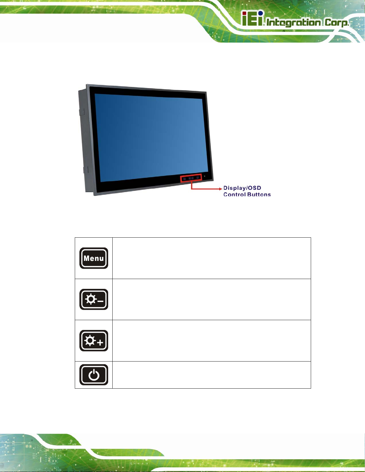
1.4 Front Panel
The front side of the S19M/S24M (Figure 1-2) is a flat panel LCD screen surrounded by
an aluminum frame. The bottom frame includes four OSD buttons and an ambient light
sensor.
Figure 1-2: Front Panel
Page 3
Page 12

1.4.1 Display Control Buttons
The display control buttons are located on the bottom right corner of the front panel. The
function of each button is described in the following diagram. These buttons can also be
used to control OSD (on-screen display). Please refer to Chapter 4 for more detail.
Figure 1-3: Display Control Buttons
S19M/S24M Marine Monitor
1.5 Bottom Panel
The bottom panel of the S19M/S24M has the following I/O interfaces (Figure 1-4):
1 x 100 V ~ 240 V AC power input jack
1 x 18 V ~ 36 V DC power input terminal block
1 x Buzzer terminal block
1 x BNC composite video input connector
1 x BNC composite video output connector
2 x DVI input connectors
1 x RJ-45 connector for remote control
1 x RS-232 DB-9 connector for remote control
1 x RS-422/485 terminal block for remote control
1 x USB Type A connector for touchscreen
2 x VGA input connectors
1 x VGA output connector
Page 4
Page 13

S19M/S24M Marine Monitor
Figure 1-4: Bottom Panel
1.6 Rear Panel
The rear panel provides access to retention screw holes that support VESA mounting.
See
Figure 1-5 and Figure 1-6.
Figure 1-5: S19M Rear Panel
Page 5
Page 14

S19M/S24M Marine Monitor
Figure 1-6: S24M Rear Panel
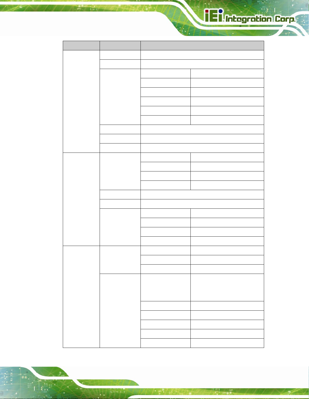
1.7 System Specifications
The technical specifications for the S19M/S24M are listed in Table 1-2.
Specifications S19M S24M
LCD Size
Panel Type
Max. Resolution
Contrast Ratio
Brightness (cd/m2)
LCD Color
Pixel Pitch (um)
19" 24”
PMVA AMVA
1280 x 1024 (5:4) 1920 x 1080 (16:9)
2000:1 5000:1
300 300
16.7M 16.7M
294 x 294 276.75 x 276.75
Page 6
Viewing Angle (H-V)
178° / 178° 178° / 178°
Page 15

S19M/S24M Marine Monitor
Specifications S19M S24M
Backlight MTBF (HRs)
Touch Controller
Touchscreen
Scalar Chip
I/O Interfaces
50,000 50,000
EXC3188 (10-point)
Projected capacitive type
STDP8028
DVI-D signal input: 2 x DVI (24-pin, female)
VGA signal input: 2 x D-sub (15-pin, female)
VGA signal output: 1 x D-sub (15-pin, female, clone of
VGA input)
Composite video input: 1 x BNC (female)
Composite video output: 1 x BNC (female)
Remote control: 1 x RS-232 DB-9 (non-isolated)
1 x RS-422/485 terminal block (5-pin,
non-isolated)
1 x RJ-45
PIP
OSD Buttons
Sensor
Power Requirement
Operating Temperature
Storage Temperature
Touchscreen: 1 x USB Type A (female)
Isolated AC power inlet: 100 V ~ 240 V AC
Isolated DC power input terminal block: 18 V ~ 36 V DC
Buzzer: 1 x Buzzer (5-pin, terminal block)
Yes
Four capacitive sensor buttons (menu, brightness down,
brightness up, LCD on/off)
Ambient light sensor (0% ~ 100%)
Dual power supply
AC power: 100V ~ 240V, 2-1A, 50-60Hz
DC power: 18V ~ 36V, 8-4A
-15ºC ~ 55ºC
-20ºC ~ 60ºC
Page 7
Page 16

Specifications S19M S24M
S19M/S24M Marine Monitor
Operating Humidity
Thermal Design
Housing
Cut-out Dimensions
(L x W)
Dimensions (L x W x D)
Mounting
Weight (Net/Gross)
IP Rating
EMC
Safety
5% ~ 95% RH
Fanless
Aluminum front, sheet metal rear (Black C)
442 mm x 373 mm 576 mm x 356 mm
463 mm x 394 mm x 76 mm 592 mm x 374 mm x 74 mm
VESA 100 mm x 100 mm
7.74 kg/11.54 kg 11.48 kg/15.97 kg
IP 66 compliant front panel
IP 22 compliant rear cover
CE, FCC
DNV, IEC 60945 4th, IACS-E10 compliant
VESA 100 mm x 100 mm or
100 mm x 200 mm
Table 1-2: System Specifications
Page 8
Page 17

S19M/S24M Marine Monitor
1.8 Dimensions
The 19M dimensions are shown below.
Figure 1-7: S19M Dimensions (mm)
Page 9
Page 18

The S24M dimensions are shown below.
S19M/S24M Marine Monitor
Page 10
Figure 1-8: S24M Dimensions (mm)
Page 19

S19M/S24M Marine Monitor
Chapter
2
2 Unpacking
Page 11
Page 20

2.1 Anti-static Precautions
WARNING:
Failure to take ESD precautions during installation may result in
permanent damage to the S19M/S24M and severe injury to the user.
Electrostatic discharge (ESD) can cause serious damage to electronic components,
including the S19M/S24M. Dry climates are especially susceptible to ESD. It is therefore
critical that whenever the S19M/S24M or any other electrical component is handled, the
following anti-static precautions are strictly adhered to.
Wear an anti-static wristband: Wearing a simple anti-static wristband can
help to prevent ESD from damaging the board.
S19M/S24M Marine Monitor
Self-grounding: Before handling the board, touch any grounded conducting
material. During the time the board is handled, frequently touch any
conducting materials that are connected to the ground.
Use an anti-static pad: When configuring the S19M/S24M, place it on an
anti-static pad. This reduces the possibility of ESD damaging the
S19M/S24M.
2.2 Unpacking Precautions
When the S19M/S24M is unpacked, please do the following:
Follow the anti-static precautions outlined in Section
Make sure the packing box is facing upwards so the S19M/S24M does not fall
out of the box.
Make sure all the components shown in Section
2.1.
2.3 are present.
Page 12
Page 21

S19M/S24M Marine Monitor
2.3 Packing List
NOTE:
If any of the components listed in the checklist below are missing, do not
proceed with the installation. Contact the IEI reseller or vendor the S19M/S24M
was purchased from or contact an IEI sales representative directly by sending
an email to
The S19M/S24M marine monitor is shipped with the following components:
Quantity Item Image
1 S19M/S24M marine monitor
1 VGA signal cable
1 DVI signal cable
1 Touchscreen USB cable
38sales@ieiworld.com.
(P/N: 32000-036200-RS)
(P/N: 32000-086600-RS)
(P/N: 32001-006100-200-RS)
1 Power cord
1 User manual and driver CD
Page 13
Page 22

2.4 Optional Items
The following are optional components which may be separately purchased:
Item and Part Number Image
Panel mounting kit
(P/N: PK-S19M-R10)
(P/N: PK-S24M-R10)
Desktop stand
(P/N: STAND-A21-R10)
S19M/S24M Marine Monitor
Page 14
Page 23

S19M/S24M Marine Monitor
3 Installation
Chapter
3
Page 15
Page 24

3.1 Installation Precautions
When installing the marine monitor, please follow the precautions listed below:
Read the user manual: The user manual provides a complete description of
the S19M/S24M, installation instructions and configuration options.
Power turned off: When installing the marine monitor, make sure the power
is off. Failing to turn off the power may cause severe injury to the body and/or
damage to the system.
Certified Engineers: Only certified engineers should install and modify
onboard functionalities.
Anti-static Discharge: If a user open the rear panel of the marine monitor, to
configure the jumpers or plug in added peripheral devices, ground themselves
first and wear an anti-static wristband.
S19M/S24M Marine Monitor
3.2 Mounting the Monitor
WARNING:
When mounting the S19M/S24M marine monitor onto a panel, it is
better to have more than one person to help with the installation to
make sure the S19M/S24M does not fall down and get damaged.
The following mounting methods are available:
Panel mounting
Stand mounting
The installation instructions are described in the following sub-sections. The mounting kits
used in the following instructions can be purchased separately. Please contact IEI sales
representatives for more detail.
Page 16
Page 25

S19M/S24M Marine Monitor
3.2.1 Panel Mounting
To mount the S19M/S24M marine monitor into a panel, please follow the steps below.
Step 1: Select the position on the panel to mount the S19M/S24M.
Step 2: Cut out a section of the panel that corresponds to the rear panel dimensions of
the S19M/S24M. The recommended cutout sizes are shown below (
Figure 3-2).
and
Figure 3-1: S19M Cutout Dimensions
Figure 3-1
Figure 3-2: S24M Cutout Dimensions
Page 17
Page 26

Step 3: Remove the panel mounting hole covers from the rear panel. Each cover is
secured to the rear panel with a retention screw. Remove the retention screw to
remove the cover.
S19M/S24M Marine Monitor
Figure 3-3: S24M Panel Mounting Hole Covers
Step 4: Slide the marine monitor through the hole until the aluminum frame is flush
against the panel.
Step 5: Insert the panel mounting clamps into the pre-formed holes along the edges of
the rear panel. The number of mounting clamps required to mount the marine
monitor to a panel is listed below.
Model Mounting Clamps
S19M 10
S24M 12
Table 3-1: Panel Mounting Clamps
Step 6: Tighten the screws that pass through the panel mounting clamps until the plastic
caps at the front of all the screws are firmly secured to the panel (
Figure 3-4).
Page 18
Step 0:
Page 27

S19M/S24M Marine Monitor
Figure 3-4: Tighten the Panel Mounting Clamp Screws
3.2.2 Stand Mounting
To mount the S19M/S24M using the stand mounting kit, please follow the steps below.
Step 1: Locate the screw holes on the rear of the S19M/S24M (
1-6). This is where the bracket will be attached.
Step 2: Align the bracket with the screw holes.
Step 3: To secure the bracket to the S19M/S24M insert the retention screws into the
screw holes and tighten them.
Figure 1-5 and Figure
Page 19
Page 28

3.3 I/O Interfaces
The S19M/S24M has the following I/O interfaces (Figure 3-5):
Figure 3-5: I/O Interfaces
S19M/S24M Marine Monitor
3.3.1 BNC Video Input and Output
The S19M/S24M equips with one BNC video input and one BNC video output connectors.
Refer to
Figure 3-5 for the connector locations.
3.3.2 Buzzer
The buzzer terminal block allows connection to a buzzer.
Pin Description
1 GND
2 485_VCC (+5V)
3 BEEP_485
4 NC
5 GND
Table 3-2: Buzzer Terminal Block Pinouts
Page 20
Page 29

S19M/S24M Marine Monitor
3.3.3 DVI Inputs
The S19M/S24M provides two DVI input connectors. Refer to Figure 3-5 for the connector
locations.
Pin Description Pin Description
1
3 GND 4
5
7 DDCDATA 8 N/C
9
11 GND 12
13
15 GND 16 Hot plug detect
17
19 GND 20
21
23 DVI CLK(+) 24 DVI CLK(-)
DVI signal differential
pair (2-)
DVI signal differential
pair (4+)
DVI signal differential
pair (1-)
DVI signal differential
pair (3+)
DVI signal differential
pair (0-)
DVI signal differential
pair (5+)
2
6 DDCLCK
10
14 5V supply
18
22 GND
DVI signal differential
pair (2+)
DVI signal differential
pair (4-)
DVI signal differential
pair (1+)
DVI signal differential
pair (3-)
DVI signal differential
pair (0+)
DVI signal differential
pair (5-)
Table 3-3: DVI Input Connector Pinouts
3.3.4 Power Inputs
The S19M/S24M provides two types of power inputs: 18V ~ 36V DC power and 100V ~
240V AC power. Refer to
Figure 3-6: 18V ~ 36V DC Power Input Terminal Block Pinouts
Figure 3-5 for the locations of the power input connectors.
Page 21
Page 30

3.3.5 RJ-45 for Remote Control
The S19M/S24M provides an RJ-45 connector for remote control.
Pin Description Pin Description
S19M/S24M Marine Monitor
R1
R2
R3
R4
R5
NC
TX+NL
TX-NL
RX+NL
RX-NL
R6
L1
L2
L3
L4
GND
NWAYEN
3.3V_NL
SPEED
3.3V_NL
Table 3-4: RJ-45 Connector Pinouts
3.3.6 RS-232 for Remote Control
The S19M/S24M provides an RS-232 DB-9 connector for remote control.
NOTE:
The default baud rate for the RS-232 connector is 38,400 bps. To
change the baud rate for the connector, the user has to modify the
firmware of the AD board.
Page 22
Pin Description Pin Description
+5V
RX_C
TX_C
NC
1
2
3
4
5 GND
6
7
8
9
NC
RTS_C
CTS_C
COM_BEEP
Table 3-5: RS-232 Connector Pinouts
Page 31

S19M/S24M Marine Monitor
3.3.7 RS-422/485 for Remote Control
The S19M/S24M provides an RS-422/485 terminal block for remote control.
NOTE:
The default baud rate for the RS-422/485 connector is 38,400 bps. To
change the baud rate for the connector, the user has to modify the
firmware of the AD board.
Pin Description
1 +RXD485
2 #RXD485
3 +TXD485
4 #TXD485
5 GND
Table 3-6: RS-422/485 Terminal Block Pinouts
3.3.8 USB for Touchscreen
The USB Type A connector allows connecting the touch panel to the system using the
supplied touchscreen USB cable.
Pin Description
1 VCC_USB
2 USB_T3 USB_T+
4 USB_GND
Figure 3-7: USB Type A Connector Pinouts
Page 23
Page 32

3.3.9 VGA Inputs
The S19M/S24M provides two VGA input connectors. Refer to Figure 3-5 for the
connector locations.
Pin Description Pin Description
1 RED 2 GREEN
3 BLUE 4 NC
5 GND 6 GND
7 GND 8 GND
9 5V 10 GND
11 NC 12 DDCDAT
13 HSYNC 14 VSYNC
15 DDCCLK
S19M/S24M Marine Monitor
Table 3-7: VGA Output Connector Pinouts
3.3.10 VGA Output
The S19M/S24M provides one VGA output connector. Refer to Figure 3-5 for the
connector location.
Pin Description Pin Description
1 RED 2 GREEN
3 BLUE 4 NC
5 GND 6 GND
7 GND 8 GND
9 VCC 10 GND
11 NC 12 DDCDA
13 HSYNC 14 VSYNC
15 DDCCLK
Table 3-8: VGA Output Connector Pinouts
Page 24
Page 33

S19M/S24M Marine Monitor
3.4 Turning On/Off the Marine Monitor
To turn on/off the marine monitor, follow the steps below:
Step 1: Ensure the marine monitor is connected to a power source. Refer to Section
3.3.4 for detailed information of the power input connectors on the S19M/S24M.
Step 2: Press the
turn on or off the monitor. Step 0:
button located on the bottom right corner of the front panel to
Page 25
Page 34

S19M/S24M Marine Monitor
4 On-Screen Display (OSD)
Chapter
4
Controls
Page 26
Page 35
S19M/S24M Marine Monitor
4.1 OSD Control Buttons
The OSD control buttons are located on the bottom right corner of the front panel.
Figure 4-1: OSD Button Locations
The function of each button is described in the following table.
Press this button to open the OSD window.
When inside the OSD menu, press this button to confirm the selection of
the item.
Press this button to decrease the backlight value.
When inside the OSD menu, press this button to scroll down, to
decrease the value, or to switch from one option to another.
Press this button to increase the backlight value.
When inside the OSD menu, press this button to scroll up, to increase
the value, or to switch from one option to another.
Press this button to exit the current menu or the OSD window.
Table 4-1: OSD Control Buttons
Page 27
Page 36

4.2 OSD Menu Structure and Options
S19M/S24M Marine Monitor
Figure 4-2: Main Menu
Table 4-2 shows the OSD menu structure and options for the S19M/S24M marine
monitor.
Level 0 Level 1 Values/Options
Backlight 0 to 100
Brightness 0 to 100
Contrast 0 to 100
Sharpness 0 to 24
Auto Adjustment Select
Vertical Position 31 to -31
Image Settings
Advanced
Horizontal Position 100 to -100
Phase 0 to 63
Clocks/Line 1180 to 1478
Auto Color
Page 28
Color
Reset Scheme No, Yes
Color T emp: 6500K, 8000K, 9300K,
User
Page 37
S19M/S24M Marine Monitor
Level 0 Level 1 Values/Options
Auto AR Off, On
Aspect Ratio Full Screen, 1:1, Aspect Ratio
PIP Mode Off, Small PIP, Side-by-Side
PIP Size 1 to 7
Display Settings
Setup
PIP
Vertical Position 0 to 100
Horizontal Position 0 to 100
Brightness 0 to 100
Contrast 0 to 100
AutoScan On, Off
Main Source VGA1, VGA2, DVI1, DVI2, VIDEO1
PIP Source VIDEO1, DVI1, DVI2
Horizontal Position 0 to 100
Vertical Position 0 to 100
OSD Settings
Menu Timeout 0 to 30
Osd Transparency 0 to 100
LedLight (Inactive) 0 to 100
LedLight (Active) 0 to 100
Language English
Factory Reset No, Yes
Misc
Gamma Yes, No
Auto Dimming No, Yes
Demo
Noise Reduction
Video Processing
CCS Mode Off, Normal, Adaptive
Dynamic NR Mode Low, Adaptive, Off, High, Medium
MPEG NR Mode On, Off
DCDi Main DCDi: Off, On
PIP DCDi: Not available to be
configured
Main MADI Mode Normal, Adaptive, Off,
LCD Overdrive Off
Split Screen Off, On
Fleshtone Adjustment Not available to be configured
Blue Stretch Not available to be configured
Page 29
Page 38

Level 0 Level 1 Values/Options
Film Mode Detection Video-3:2, Video-3:2-2:2, Off,
S19M/S24M Marine Monitor
Film Mode &
Film Display Mode Not available to be configured
Scaling
Ver t. D ynami c Scaling Not available to be configured
Horiz. Dynamic Scaling
Smart ISP Not available to be configured
Firmware Version Displays firmware version
Table 4-2: OSD Menu Structure and Options
Video-2:2
Not available to be configured
Page 30
Page 39

S19M/S24M Marine Monitor
5 IEI Monitor Remote
Chapter
5
Application
Page 31
Page 40

5.1 Overview
The IEI Monitor Remote Application allows remote control of the marine monitor via LAN,
RS-232 or RS-422/485 connection to a computer. Refer to the following sections for
S19M/S24M Marine Monitor
detailed information.
5.2 Launching the IEI Monitor Remote Application
Step 1: Insert the driver CD into an optical disk drive connected to the system.
Step 2: Locate the IEIMonitorRemoteAP file in the driver CD. Double click the file to
launch the application.
The user may copy the IEIMonitorRemoteAP file to the Windows desktop, and
then double click the file from the Windows desktop to launch the application.
Figure 5-1: IEI Monitor Remote Application Screen
5.3 Remote Control via RS-232
To remotely control the marine monitor via RS-232 connection, please follow the steps
below.
Step 1: Ensure the marine monitor is connected to the computer via the RS-232
Figure 1-4 for the location of the RS-232 connector on the
Page 32
interface. Refer to
S19M/S24M.
Page 41

S19M/S24M Marine Monitor
NOTE:
The application will scan from COM1 to COM5 of the computer and will
use the interface (RS-232 or RS-422/485) which is being detected first.
If the user wants to use RS-232 interface, but the RS-422/485
connection is being detected first, please unplug the RS-422/485 cable
from the computer.
Step 2: Click the RS232/422/485 tab. The ID of the connected marine monitor should be
displayed on the device list (
click Scan Device to detect the connected marine monitor again.
Figure 5-2). If the device ID is not being displayed,
NOTE:
When using the RS-232 interface, only one marine monitor can be
controlled remotely.
Figure 5-2: IEI Monitor Remote AP – RS-232
Step 3: Click the device ID to select the device to control. The user can set the device ID,
adjust the brightness, turn on/off the monitor, and turn on/off the buzzer. Step 0:
Page 33
Page 42

5.4 Remote Control via RS-422/485
To remotely control the marine monitor via RS-422/485 connection, please follow the
steps below.
Step 1: Ensure the marine monitor is connected to the computer via the RS-422/485
S19M/S24M Marine Monitor
interface. Refer to
on the S19M/S24M.
Figure 1-4 for the location of the RS-422/485 terminal block
NOTE:
The application will scan from COM1 to COM5 of the computer and will
use the interface (RS-232 or RS-422/485) which is being detected first.
If the user wants to use RS-422/485 interface, but the RS-232
connection is being detected first, please unplug the RS-232 cable
from the computer.
Step 2: Click the RS232/422/485 tab. The ID of the connected marine monitors should
be displayed on the device list (
displayed, click Scan Device to detect the connected marine monitor again.
Figure 5-3). If the device ID is not being
Page 34
NOTE:
When using the RS-422/485 interface, up to 16 marine monitors can be
controlled remotely. However, the user has to set different ID for each
connected marine monitor.
Page 43

S19M/S24M Marine Monitor
Figure 5-3: IEI Monitor Remote AP – RS-422/485
Step 3: Click the device ID to select the device to control. The user can set the device ID,
adjust the brightness, turn on/off the monitor, and turn on/off the buzzer. Step 0:
5.5 Remote Control via LAN
To remotely control the marine monitor via LAN, please follow the steps below.
Step 1: Ensure the marine monitor is connected to the network via the RJ-45 interface.
Refer to
NOTE:
The marine monitor and the computer should be under the same
domain.
Figure 1-4 for the location of the RJ-45 connector on the S19M/S24M.
Page 35
Page 44

Step 2: Click the LAN tab. The ID and IP address of the connected marine monitors
S19M/S24M Marine Monitor
should be displayed on the device list (
address are not being displayed, click Scan Device to detect the connected
marine monitor again.
Figure 5-4). If the device ID and IP
NOTE:
When using the RJ-45 interface, up to 16 marine monitors can be
controlled remotely.
Page 36
Figure 5-4: IEI Monitor Remote AP – LAN
Step 3: Click the IP address to select the device to control. The user can set the device
ID and IP address, adjust the brightness, turn on/off the monitor, and turn on/off
the buzzer. Step 0:
Page 45

S19M/S24M Marine Monitor
Appendix
A
A Regulatory Compliance
Page 37
Page 46

S19M/S24M Marine Monitor
DECLARATION OF CONFORMITY
This equipment is in conformity with the following EU directives:
EMC Directive 2004/108/EC
Low-Voltage Directive 2006/95/EC
RoHS II Directive 2011/65/EU
Ecodesign Directive 2009/125/EC
If the user modifies and/or install other devices in the equipment, the CE conformity
declaration may no longer apply.
If this equipment has telecommunications functionality, it also complies with the
requirements of the R&TTE Directive 1999/5/EC.
English
IEI Integration Corp declares that this equipment is in compliance with the essential
requirements and other relevant provisions of Directive 1999/5/EC.
Български [Bulgarian]
IEI Integration Corp. декларира, че този оборудване е в съответствие със
съществените изисквания и другите приложими правила на Директива 1999/5/ЕС.
Česky [Czech]
IEI Integration Corp tímto prohlašuje, že tento zařízení je ve shodě se základními
požadavky a dalšími příslušnými ustanoveními směrnice 1999/5/ES.
Dansk [Danish]
IEI Integration Corp erklærer herved, at følgende udstyr overholder de væsentlige krav og
øvrige relevante krav i direktiv 1999/5/EF.
Deutsch [German]
IEI Integration Corp, erklärt dieses Gerät entspricht den grundlegenden Anforderungen
und den weiteren entsprechenden Vorgaben der Richtlinie 1999/5/EU.
Eesti [Estonian]
IEI Integration Corp deklareerib seadme seadme vastavust direktiivi 1999/5/EÜ
põhinõuetele ja nimetatud direktiivist tulenevatele teistele asjakohastele sätetele.
Page 38
Page 47

S19M/S24M Marine Monitor
Español [Spanish]
IEI Integration Corp declara que el equipo cumple con los requisitos esenciales y
cualesquiera otras disposiciones aplicables o exigibles de la Directiva 1999/5/CE.
Ελληνική [Greek]
IEI Integration Corp ΔΗΛΩΝΕΙ ΟΤΙ ΕΞΟΠΛΙΣΜΟΣ ΣΥΜΜΟΡΦΩΝΕΤΑΙ ΠΡΟΣ ΤΙΣ
ΟΥΣΙΩΔΕΙΣ ΑΠΑΙΤΗΣΕΙΣ ΚΑΙ ΤΙΣ ΛΟΙΠΕΣ ΣΧΕΤΙΚΕΣ ΔΙΑΤΑΞΕΙΣ ΤΗΣ ΟΔΗΓΙΑΣ
1999/5/ΕΚ.
Français [French]
IEI Integration Corp déclare que l'appareil est conforme aux exigences essentielles et aux
autres dispositions pertinentes de la directive 1999/5/CE.
Italiano [Italian]
IEI Integration Corp dichiara che questo apparecchio è conforme ai requisiti essenziali ed
alle altre disposizioni pertinenti stabilite dalla direttiva 1999/5/CE.
Latviski [Latvian]
IEI Integration Corp deklarē, ka iekārta atbilst būtiskajām prasībām un citiem ar to
saistītajiem noteikumiem Direktīvas 1999/5/EK.
Lietuvių [Lithuanian]
IEI Integration Corp deklaruoja, kad šis įranga atitinka esminius reikalavimus ir kitas
1999/5/EB Direktyvos nuostatas.
Nederlands [Dutch]
IEI Integration Corp dat het toestel toestel in overeenstemming is met de essentiële eisen
en de andere relevante bepalingen van richtlijn 1999/5/EG.
Malti [Maltese]
IEI Integration Corp jiddikjara li dan prodott jikkonforma mal-ħtiġijiet essenzjali u ma
provvedimenti oħrajn relevanti li hemm fid-Dirrettiva 1999/5/EC.
Magyar [Hungarian]
IEI Integration Corp nyilatkozom, hogy a berendezés megfelel a vonatkozó alapvetõ
követelményeknek és az 1999/5/EC irányelv egyéb elõírásainak.
Polski [Polish]
IEI Integration Corp oświadcza, że wyrobu jest zgodny z zasadniczymi wymogami oraz
pozostałymi stosownymi postanowieniami Dyrektywy 1999/5/EC.
Português [Portuguese]
IEI Integration Corp declara que este equipamento está conforme com os requisitos
essenciais e outras disposições da Directiva 1999/5/CE.
Page 39
Page 48

Româna [Romanian]
IEI Integration Corp declară că acest echipament este in conformitate cu cerinţele
esenţiale şi cu celelalte prevederi relevante ale Directivei 1999/5/CE.
Slovensko [Slovenian]
IEI Integration Corp izjavlja, da je ta opreme v skladu z bistvenimi zahtevami in ostalimi
relevantnimi določili direktive 1999/5/ES.
Slovensky [Slovak]
IEI Integration Corp týmto vyhlasuje, že zariadenia spĺňa základné požiadavky a všetky
príslušné ustanovenia Smernice 1999/5/ES.
Suomi [Finnish]
IEI Integration Corp vakuuttaa täten että laitteet on direktiivin 1999/5/EY oleellisten
vaatimusten ja sitä koskevien direktiivin muiden ehtojen mukainen.
Svenska [Swedish]
IEI Integration Corp förklarar att denna utrustningstyp står I överensstämmelse med de
S19M/S24M Marine Monitor
väsentliga egenskapskrav och övriga relevanta bestämmelser som framgår av direktiv
1999/5/EG.
Page 40
Page 49

S19M/S24M Marine Monitor
FCC WARNING
This equipment complies with Part 15 of the FCC Rules. Operation is subject to the
following two conditions:
This device may not cause harmful interference, and
This device must accept any interference received, including interference
This equipment has been tested and found to comply with the limits for a Class A digital
device, pursuant to part 15 of the FCC Rules. These limits are designed to provide
reasonable protection against harmful interference when the equipment is operated in a
commercial environment. This equipment generates, uses, and can radiate radio
frequency energy and, if not installed and used in accordance with the instruction
manual, may cause harmful interference to radio communications. Operation of this
equipment in a residential area is likely to cause harmful interference in which case the
that may cause undesired operation.
user will be required to correct the interference at his own expense.
Page 41
Page 50

S19M/S24M Marine Monitor
Appendix
B
B Safety Precautions
Page 42
Page 51

S19M/S24M Marine Monitor
WARNING:
The precautions outlined in this chapter should be strictly followed.
Failure to follow these precautions may result in permanent damage to
the S19M/S24M.
B.1 Safety Precautions
Please follow the safety precautions outlined in the sections that follow:
B.1.1 General Safety Precautions
Please ensure the following safety precautions are adhered to at all times.
Follow the electrostatic precautions outlined below whenever the
S19M/S24M is opened.
Make sure the power is turned off and the power cord is disconnected
whenever the S19M/S24M is being installed, moved or modified.
Do not apply voltage levels that exceed the specified voltage range.
Doing so may cause fire and/or an electrical shock.
Electric shocks can occur if the S19M/S24M chassis is opened when the
S19M/S24M is running.
Do not drop or insert any objects into the ventilation openings of the
S19M/S24M.
If considerable amounts of dust, water, or fluids enter the S19M/S24M,
turn off the power supply immediately, unplug the power cord, and contact the
S19M/S24M vendor.
DO NOT:
o Drop the S19M/S24M against a hard surface.
o Strike or exert excessive force onto the LCD panel.
o Touch any of the LCD panels with a sharp object
o In a site where the ambient temperature exceeds the rated temperature
Page 43
Page 52

B.1.2 Anti-static Precautions
WARNING:
Failure to take ESD precautions during the installation of the
S19M/S24M may result in permanent damage to the S19M/S24M and
severe injury to the user.
Electrostatic discharge (ESD) can cause serious damage to electronic components,
including the S19M/S24M. Dry climates are especially susceptible to ESD. It is therefore
critical that whenever the S19M/S24M is opened and any of the electrical components are
handled, the following anti-static precautions are strictly adhered to.
Wear an anti-static wristband: Wearing a simple anti-static wristband can
S19M/S24M Marine Monitor
help to prevent ESD from damaging any electrical component.
Self-grounding: Before handling any electrical component, touch any
grounded conducting material. During the time the electrical component is
handled, frequently touch any conducting materials that are connected to the
ground.
Use an anti-static pad: When configuring or working with an electrical
component, place it on an anti-static pad. This reduces the possibility of ESD
damage.
Only handle the edges of the electrical component: When handling the
electrical component, hold the electrical component by its edges.
Page 44
Page 53

S19M/S24M Marine Monitor
B.1.3 Product Disposal
CAUTION:
Risk of explosion if battery is replaced by an incorrect type. Only
certified engineers should replace the on-board battery.
Dispose of used batteries according to instructions and local
regulations.
Outside the European Union - If you wish to dispose of used electrical and
electronic products outside the European Union, please contact your local
authority so as to comply with the correct disposal method.
Within the European Union:
EU-wide legislation, as implemented in each Member State, requires that
waste electrical and electronic products carrying the mark (left) must be
disposed of separately from normal household waste. This includes
monitors and electrical accessories, such as signal cables or power cords.
When you need to dispose of your display products, please follow the
guidance of your local authority, or ask the shop where you purchased the product. The
mark on electrical and electronic products only applies to the current European Union
Member States.
Please follow the national guidelines for electrical and electronic product disposal.
B.2 Maintenance and Cleaning Precautions
When maintaining or cleaning the S19M/S24M, please follow the guidelines below.
B.2.1 Maintenance and Cleaning
Prior to cleaning any part or component of the S19M/S24M, please read the details below.
Page 45
Page 54

Except for the LCD panel, never spray or squirt liquids directly onto any other
components. To clean the LCD panel, gently wipe it with a piece of soft dry
cloth or a slightly moistened cloth.
Never use alcohol to clean the external chassis.
The interior of the S19M/S24M does not require cleaning. Keep fluids away
from the S19M/S24M interior.
Be cautious of all small removable components when vacuuming the
S19M/S24M.
Turn the S19M/S24M off before cleaning the S19M/S24M.
Never drop any objects or liquids through the openings of the S19M/S24M.
Be cautious of any possible allergic reactions to solvents or chemicals used
when cleaning the S19M/S24M.
Avoid eating, drinking and smoking within vicinity of the S19M/S24M.
B.2.2 Cleaning Tools
S19M/S24M Marine Monitor
Some components in the S19M/S24M may only be cleaned using a product specifically
designed for the purpose. In such case, the product will be explicitly mentioned in the
cleaning tips. Below is a list of items to use when cleaning the S19M/S24M.
Cloth – Although paper towels or tissues can be used, a soft, clean piece of
cloth is recommended when cleaning the S19M/S24M.
Water – A cloth moistened with water can be used to clean the S19M/S24M.
Using solvents – The use of solvents is not recommended when cleaning the
S19M/S24M as they may damage the plastic parts.
Vacuum cleaner – Using a vacuum specifically designed for computers is
one of the best methods of cleaning the S19M/S24M. Dust and dirt can
restrict the airflow in the S19M/S24M and cause its circuitry to corrode.
Cotton swabs - Cotton swaps moistened with water are excellent tools for
wiping hard to reach areas.
Foam swabs - Whenever possible, it is best to use lint free swabs such as
foam swabs for cleaning.
Page 46
Page 55

S19M/S24M Marine Monitor
Appendix
C
C Hazardous Materials
Disclosure
Page 47
Page 56

S19M/S24M Marine Monitor
C.1 Hazardous Material Disclosure Table for IPB Products
Certified as RoHS Compliant Under 2002/95/EC Without
Mercury
The details provided in this appendix are to ensure that the product is compliant with the
Peoples Republic of China (China) RoHS standards. The table below acknowledges the
presences of small quantities of certain materials in the product, and is applicable to China
RoHS only.
A label will be placed on each product to indicate the estimated “Environmentally Friendly
Use Period” (EFUP). This is an estimate of the number of years that these substances
would “not leak out or undergo abrupt change.” This product may contain replaceable
sub-assemblies/components which have a shorter EFUP such as batteries and lamps.
These components will be separately marked.
Please refer to the table on the next page.
Page 48
Page 57

S19M/S24M Marine Monitor
Toxic or Hazardous Substances and Elements Part Name
Housing
Display
Printed Circuit
Lead
(Pb)
O O O O O O
O O O O O O
O O O O O O
Mercury
(Hg)
Board
Metal Fasteners
Cable Assembly
Fan Assembly
Power Supply
O O O O O O
O O O O O O
O O O O O O
O O O O O O
Assemblies
Battery O
O O O O O
Cadmium
(Cd)
Hexavalent
Chromium
(CR(VI))
Polybrominated
Biphenyls
(PBB)
Polybrominated
Diphenyl Ethers
(PBDE)
O: This toxic or hazardous substance is contained in all of the homogeneous materials for the part is below
the limit requirement in SJ/T11363-2006
X: This toxic or hazardous substance is contained in at least one of the homogeneous materials for this part
is above the limit requirement in SJ/T11363-2006
Page 49
Page 58

S19M/S24M Marine Monitor
此附件旨在确保本产品符合中国 RoHS 标准。以下表格标示此产品中某有毒物质的含量符
合中国 RoHS 标准规定的限量要求。
本产品上会附有”环境友好使用期限”的标签,此期限是估算这些物质”不会有泄漏或突变”的
年限。本产品可能包含有较短的环境友好使用期限的可替换元件,像是电池或灯管,这些元
件将会单独标示出来。
部件名称
壳体
显示
印刷电路板
金属螺帽
电缆组装
风扇组装
电力供应组装
电池
有毒有害物质或元素
铅
(Pb)
汞
(Hg)
镉
(Cd)
六价铬
(CR(VI))
多溴联苯
(PBB)
多溴二苯醚
(PBDE)
O O O O O O
O O O O O O
O O O O O O
O O O O O O
O O O O O O
O O O O O O
O O O
O
O O O O O
O
O O
O: 表示该有毒有害物质在该部件所有物质材料中的含量均在 SJ/T11363-2006 标准规定的限量要求以下。
X: 表示该有毒有害物质至少在该部件的某一均质材料中的含量超出 SJ/T11363-2006 标准规定的限量要求。
Page 50
 Loading...