

IEI Technology PPC-F12B-BTi, PPC-F15B-BTi, PPC-F17B-BTi, PPC-F12B-BTi-J1/2G/R-R10, PPC-F12B-BTi-J1/2G/PC-R10 User Manual
...Page 1

®
®
PPC-F12B/15B/17B-BTi Panel PC
PPC-F12B/15B/17B-BTi Panel PC
MODEL:
PPC-F12B/15B/17B-BTi
Industrial Panel PC with Intel
Touchscreen, Dual PCIe Mini, USB 3.0, HDMI
SATA 6Gb/s, Dual PCIe GbE, iRIS-2400,
IP 65 Compliant Front Panel and RoHS Compliant
User Manual
Celeron
Processor J1900,
Rev. 1.01 – July 31, 2015
Page i
Page 2

Date Version Changes
July 31, 2015 1.01 Modified Section 1.2: Model Variation
Modified Section 1.6: Bottom Panel
May 26, 2015 1.00 Initial release
PPC-F12B/15B/17B-BTi Panel PC
Revision
Page ii
Page 3

PPC-F12B/15B/17B-BTi Panel PC
COPYRIGHT NOTICE
The information in this document is subject to change without prior notice in order to
improve reliability, design and function and does not represent a commitment on the part
of the manufacturer.
In no event will the manufacturer be liable for direct, indirect, special, incidental, or
consequential damages arising out of the use or inability to use the product or
documentation, even if advised of the possibility of such damages.
This document contains proprietary information protected by copyright. All rights are
Copyright
reserved. No part of this manual may be reproduced by any mechanical, electronic, or
other means in any form without prior written permission of the manufacturer.
TRADEMARKS
All registered trademarks and product names mentioned herein are used for identification
purposes only and may be trademarks and/or registered trademarks of their respective
owners.
Page iii
Page 4

PPC-F12B/15B/17B-BTi Panel PC
Manual Conventions
WARNING
Warnings appear where overlooked details may cause damage to the
equipment or result in personal injury. Warnings should be taken
seriously.
CAUTION
Cautionary messages should be heeded to help reduce the chance of
losing data or damaging the product.
NOTE
These messages inform the reader of essential but non-critical
information. These messages should be read carefully as any directions
or instructions contained therein can help avoid making mistakes.
HOT SURFACE
This symbol indicates a hot surface that should not be touched without
taking care.
Page iv
Page 5

PPC-F12B/15B/17B-BTi Panel PC
Table of Contents
1 INTRODUCTION.......................................................................................................... 1
1.1 OVERVIEW.................................................................................................................. 2
1.2 MODEL VARIATIONS ................................................................................................... 3
1.3 FEATURES................................................................................................................... 3
1.4 FRONT PANEL............................................................................................................. 4
1.5 REAR PANEL............................................................................................................... 4
1.6 BOTTOM PANEL.......................................................................................................... 5
1.7 DIMENSIONS............................................................................................................... 7
1.7.1 PPC-F12B-BTi Dimensions............................................................................... 7
1.7.2 PPC-F15B-BTi Dimensions............................................................................... 8
1.7.3 PPC-F17B-BTi Dimensions............................................................................... 9
1.8 SPECIFICATIONS ....................................................................................................... 10
2 UNPACKING............................................................................................................... 12
2.1 UNPACKING.............................................................................................................. 13
2.2 PACKING LIST........................................................................................................... 14
2.3 OPTIONAL ITEMS...................................................................................................... 15
3 INSTALLATION ......................................................................................................... 16
ANTI-STATIC PRECAUTIONS...................................................................................... 17
3.1
3.2 INSTALLATION PRECAUTIONS ................................................................................... 17
3.3
PREINSTALLED COMPONENTS................................................................................... 18
3.4 INST ALLATION AND CONFIGURATION STEPS ............................................................. 18
3.5 REMOVING THE BACK COVER .................................................................................. 19
3.6 SO-DIMM INSTALLATION ....................................................................................... 19
3.7 HDD INSTALLATION................................................................................................. 21
3.8 MSATA MODULE INSTALLATION.............................................................................. 23
3.9 IRIS-2400 MODULE INSTALLATION.......................................................................... 25
3.10 AT/ATX MODE SELECTION.................................................................................... 28
3.11 MOUNTING THE SYSTEM ........................................................................................ 28
3.1 1.1 Wall Mounting................................................................................................ 28
Page v
Page 6

PPC-F12B/15B/17B-BTi Panel PC
3.11.2 Panel Mounting.............................................................................................. 31
3.11.3 Rack and Cabinet Installation........................................................................ 35
3.1 1.4 Arm Mounting ................................................................................................ 37
3.11.5 Stand Mounting .............................................................................................. 39
SERIAL DEVICE CONNECTION ................................................................................ 41
3.12
3.12.1 RS-232 Serial Ports (COM1, COM2)............................................................ 41
3.12.2 RS-232/422/485 Serial Port (COM3) ............................................................ 42
3.13 POWERING ON THE SYSTEM................................................................................... 42
3.14 RESET THE SYSTEM................................................................................................ 43
3.15 CLEAR CMOS........................................................................................................ 43
3.16 DRIVER INSTALLATION........................................................................................... 44
3.16.1 Keypad AP...................................................................................................... 45
3.17
IPMI SETUP PROCEDURE ....................................................................................... 45
3.17.1 Managed System Hardware Setup ................................................................. 45
3.17.2 Using the IEI iMAN Web GUI........................................................................ 45
4 SYSTEM MAINTENANCE ....................................................................................... 48
4.1 SYSTEM MAINTENANCE INTRODUCTION .................................................................. 49
4.2 MOTHERBOARD REPLACEMENT ............................................................................... 49
5 BIOS SETUP................................................................................................................ 50
5.1 INTRODUCTION......................................................................................................... 51
5.1.1 Starting Setup................................................................................................... 51
5.1.2 Using Setup...................................................................................................... 51
5.1.3 Getting Help..................................................................................................... 52
5.1.4 Unable to Reboot after Configuration Changes
.............................................. 52
5.1.5 BIOS Menu Bar................................................................................................ 52
5.2 MAIN........................................................................................................................ 53
5.3 ADVANCED............................................................................................................... 54
5.3.1 ACPI Settings................................................................................................... 55
5.3.2 F81866 Super IO Configuration...................................................................... 56
5.3.2.1 Serial Port n Configuration....................................................................... 57
5.3.3 iWDD H/W Monitor......................................................................................... 62
5.3.4 RTC Wake Settings........................................................................................... 63
5.3.5 Serial Port Console Redirection...................................................................... 64
Page vi
Page 7

PPC-F12B/15B/17B-BTi Panel PC
5.3.5.1 Console Redirection Settings.................................................................... 65
5.3.6 CPU Configuration.......................................................................................... 67
5.3.7 IDE Configuration........................................................................................... 69
5.3.8 USB Configuration........................................................................................... 70
5.3.9 iEi Feature....................................................................................................... 73
CHIPSET ................................................................................................................... 74
5.4
5.4.1 North Bridge .................................................................................................... 75
5.4.1.1 Intel IGD Configuration............................................................................ 75
5.4.2 South Bridge..................................................................................................... 77
5.4.2.1 PCI Express Configuration....................................................................... 78
5.5 SECURITY................................................................................................................. 79
5.6
BOOT........................................................................................................................ 80
5.7 SAVE & EXIT ............................................................................................................ 82
5.8 SERVER MGMT......................................................................................................... 83
5.8.1 System Event Log............................................................................................. 84
5.8.2 BMC Network Configuration........................................................................... 85
6 INTERFACE CONNECTORS................................................................................... 87
6.1 PERIPHERAL INTERFACE CONNECTORS..................................................................... 88
6.2 INTERNAL PERIPHERAL CONNECTORS ...................................................................... 89
6.2.1 Audio Connector (AUDIO1)............................................................................ 91
6.2.2 Chassis Intrusion Connector (CHASSIS1)....................................................... 91
6.2.3 Debug Port (DBG_PORT1)............................................................................. 91
6.2.4 DIO Connector (DIO1).................................................................................... 92
6.2.5 EC Debug Port (CN2)...................................................................................... 92
6.2.6 Fan Connector (CPU_FAN1)........................................................................... 93
6.2.7 Front Panel Connector (F_PANEL1)............................................................... 93
2
6.2.8 I
C Connector (I2C1)....................................................................................... 93
6.2.9 IPMI Active LED Connector (LEDCN1)......................................................... 94
6.2.10 Keyboard and Mouse Connector (KB_MS1)................................................. 94
6.2.11 Keypad Connector (OSD1) ............................................................................ 94
6.2.12 LAN Active LED Connectors (LAN_LED1)................................................... 95
6.2.13 LVDS Connector (LVDS1) ............................................................................. 95
6.2.14 LVDS Backlight Connector (INVERTER1).................................................... 96
6.2.15 PCIe Mini (MINI_PCIE1) and mSATA (M_SATA1) Card Slots..................... 96
Page vii
Page 8

PPC-F12B/15B/17B-BTi Panel PC
6.2.16 Power Button Connector (PWR_BTN1) ........................................................ 97
6.2.17 Power Source Connector (PWR1) ................................................................. 97
6.2.18 Reset Button Connector (RST_BTN2)............................................................ 97
6.2.19 Resistive Touchscreen Connector (TOUCH1) ............................................... 98
6.2.20 RS-232 Connector (COM4, COM5) .............................................................. 98
6.2.21 SATA 6Gb/s Connectors (SATA1, SATA2)...................................................... 99
6.2.22 SATA Power Connectors (SATA_PWR1, SATA_PWR2)................................. 99
6.2.23 SMBus Connector (SMB1)............................................................................. 99
6.2.24 SPI Flash Connector (JSPI1)....................................................................... 100
6.2.25 SPI Flash (EC) Connector (JSPI2).............................................................. 100
6.2.26 U3 Firmware Programming Connector (JP2)............................................. 100
6.2.27 USB 2.0 Connector (USB1) ......................................................................... 101
6.3 EXTERNAL INTERFACE PANEL CONNECTORS.......................................................... 101
6.3.1 HDMI Connector (HDMI1)........................................................................... 102
6.3.2 GbE Connectors (LAN1, LAN2) .................................................................... 102
6.3.3 RS-232 Serial Ports (COM1, COM2)............................................................ 102
6.3.4 RS-232/422/485 Serial Port (COM3) ............................................................ 103
6.3.5 USB 2.0 Connectors (USB_CON1)................................................................ 103
6.3.6 USB 3.0 Connectors (USB3_CON1).............................................................. 103
6.3.7 VGA Connector (VGA1)................................................................................. 104
6.4 PRECONFIGURED JUMPERS ..................................................................................... 104
6.4.1 Backlight Voltage Selection Jumper (JP1)..................................................... 105
6.4.2 LVDS Panel Resolution Selection Switch (SW1)........................................... 105
6.4.3 Panel Voltage Selection Jumper (JLCD_PWR1)........................................... 106
A REGULATORY COMPLIANCE............................................................................ 107
B BIOS CONFIGURATION OPTIONS......................................................................112
BIOS CONFIGURATION OPTIONS ............................................................................113
B.1
C SAFETY PRECAUTIONS........................................................................................115
C.1 SAFETY PRECAUTIONS............................................................................................116
C.1.1 General Safety Precautions............................................................................116
C.1.2 Anti-static Precautions...................................................................................117
C.1.3 Product Disposal............................................................................................117
C.2 MAINTENANCE AND CLEANING PRECAUTIONS .......................................................118
Page viii
Page 9

PPC-F12B/15B/17B-BTi Panel PC
C.2.1 Maintenance and Cleaning ............................................................................118
C.2.2 Cleaning Tools................................................................................................119
D WA TCHDOG TIMER .............................................................................................. 120
E HAZARDOUS MATERIALS DISCLOSURE ....................................................... 123
HAZARDOUS MATERIAL DISCLOSURE TABLE FOR IPB PRODUCTS CERTIFIED AS
E.1
ROHS COMPLIANT UNDER 2002/95/EC WITHOUT MERCURY ..................................... 124
Page ix
Page 10

PPC-F12B/15B/17B-BTi Panel PC
List of Figures
Figure 1-1: PPC-F12B/15B/17B-BTi Series Panel PC..................................................................2
Figure 1-2: Front View....................................................................................................................4
Figure 1-3: PPC-F17B-BTi Rear View............................................................................................4
Figure 1-4: PPC-F12B-BTi Bottom View.......................................................................................5
Figure 1-5: PPC-F15B/F17B-BTi Bottom View.............................................................................6
Figure 1-6: PPC-F12B-BTi Dimensions (mm) ..............................................................................7
Figure 1-7: PPC-F15B-BTi Dimensions (mm) ..............................................................................8
Figure 1-8: PPC-F17B-BTi Dimensions (mm) ..............................................................................9
Figure 3-1: PPC-F17B-BTi Back Cover Retention Screws .......................................................19
Figure 3-2: SO-DIMM Slot Location ............................................................................................20
Figure 3-3: SO-DIMM Installation................................................................................................20
Figure 3-4: PPC-F17B-BTi HDD Bracket Retention Screws.....................................................21
Figure 3-5: HDD Retention Screws.............................................................................................22
Figure 3-6: PPC-F17B-BTi HDD Installation...............................................................................22
Figure 3-7: PCIe Mini Card Slot which supports mSATA.........................................................23
Figure 3-8: Removing the Retention Screws.............................................................................24
Figure 3-9: Inserting the PCIe Mini Card into the Slot at an Angle..........................................24
Figure 3-10: Securing the PCIe Mini Card..................................................................................25
Figure 3-11: Motherboard Retention Screws.............................................................................26
Figure 3-12: iRIS-2400 Module Slot Location ............................................................................26
Figure 3-13: iRIS-2400 Module Installation................................................................................27
Figure 3-14: AT/ATX Mode Selection..........................................................................................28
Figure 3-15: Wall-mounting Bracket...........................................................................................29
Figure 3-16: Mount the Chassis..................................................................................................30
Figure 3-17: Secure the Chassis.................................................................................................31
Figure 3-18: PPC-F17B-BTi Mounting Bracket Installation......................................................32
Figure 3-19: PPC-F12B-BTi Panel Cutout Dimensions.............................................................32
Figure 3-20: PPC-F15B-BTi Panel Cutout Dimensions.............................................................33
Figure 3-21: PPC-F17B-BTi Panel Cutout Dimensions.............................................................33
Figure 3-22: Tighten the Mounting Clamp Screws....................................................................34
Figure 3-23: The Rack/Cabinet Bracket......................................................................................35
Page x
Page 11

PPC-F12B/15B/17B-BTi Panel PC
Figure 3-24: Secure the Rack/Cabinet Bracket..........................................................................36
Figure 3-25: Install into a Rack/Cabinet .....................................................................................37
Figure 3-26: Arm Mounting Retention Screw Holes..................................................................38
Figure 3-27: Arm Mounting (ARM-11-RS)...................................................................................39
Figure 3-28: Stand Mounting Retention Screw Holes...............................................................40
Figure 3-29: Stand Mounting (Stand-Axx)..................................................................................40
Figure 3-30: Serial Port Locations..............................................................................................41
Figure 3-31: Power Input Connector Pinouts ............................................................................42
Figure 3-32: Power Connectors and Power Button ..................................................................43
Figure 3-33: Reset Button Location............................................................................................43
Figure 3-34: Clear CMOS Button Location.................................................................................43
Figure 3-35: Keypad AP...............................................................................................................45
Figure 3-36: IEI iMAN Web Address............................................................................................46
Figure 3-37: IEI iMAN Web GUI....................................................................................................47
Figure 6-1: Main Board Layout Diagram (Front Side)...............................................................88
Figure 6-2: Main Board Layout Diagram (Solder Side).............................................................89
Page xi
Page 12

PPC-F12B/15B/17B-BTi Panel PC
List of Tables
Table 1-1: Model Variations...........................................................................................................3
Table 1-2: System Specifications................................................................................................11
Table 2-1: Packing List.................................................................................................................14
Table 2-2: Optional Items.............................................................................................................15
Table 3-1: RS-232 Serial Port (COM1, COM2) Pinouts..............................................................41
Table 3-2: RS-232/422/485 Serial Port (COM3) Pinouts ............................................................42
Table 5-1: BIOS Navigation Keys................................................................................................52
Table 6-1: Peripheral Interface Connectors...............................................................................90
Table 6-2: Audio Connector (AUDIO1) Pinouts.........................................................................91
Table 6-3: Chassis Intrusion Connector (CHASSIS1) Pinouts.................................................91
Table 6-4: Debug Port (DBG_PORT1) Pinouts...........................................................................91
Table 6-5: DIO Connector (DIO1) Pinouts ..................................................................................92
Table 6-6: EC Debug Port (CN2) Pinouts....................................................................................92
Table 6-7: Fan Connector (CPU_FAN1) Pinouts........................................................................93
Table 6-8: Front Panel Connector (F_PANEL1) Pinouts...........................................................93
Table 6-9: I2C Connector (I2C1) Pinouts.....................................................................................93
Table 6-10: IPMI Active LED Connector (LEDCN1) Pinouts.....................................................94
Table 6-11: Keyboard and Mouse Connector (KB_MS1) Pinouts............................................94
Table 6-12: Keypad Connector (OSD1) Pinouts........................................................................94
Table 6-13: LAN Active LED Connectors (LAN_LED1) Pinouts...............................................95
Table 6-14: LVDS Connector (LVDS1) Pinouts..........................................................................95
Table 6-15: LVDS Backlight Connector (INVERTER1) Pinouts................................................96
Table 6-16: PCIe Mini (MINI_PCIE1) and mSATA (M_SATA1) Card Pinouts...........................97
Table 6-17: Power Button Connector (PWR_BTN1) Pinouts....................................................97
Table 6-18: Power Source Connector (PWR1) Pinouts.............................................................97
Table 6-19: Reset Button Connector (RST_BTN2) Pinouts......................................................97
Table 6-20: Resistive Touchscreen Connector (TOUCH1) Pinouts.........................................98
Table 6-21: RS-232 Connector (COM4, COM5) Pinouts............................................................98
Table 6-22: SATA 6Gb/s Connectors (SATA1, SATA2) Pinouts ..............................................99
Table 6-23: SATA Power Connectors (SATA_PWR1, SATA_PWR2) Pinouts.........................99
Table 6-24: SMBus Connector (SMB1) Pinouts.........................................................................99
Page xii
Page 13

PPC-F12B/15B/17B-BTi Panel PC
Table 6-25: SPI Flash Connector (JSPI1) Pinouts.................................................................. 100
Table 6-26: SPI Flash (EC) Connector (JSPI2) Pinouts.......................................................... 100
Table 6-27: U3 Firmware Programming Connector (JP2) Pinouts ....................................... 101
Table 6-28: USB 2.0 Connector (USB1) Pinouts..................................................................... 101
Table 6-29: Rear Panel Connectors......................................................................................... 101
Table 6-30: HDMI Connector (HDMI1) Pinouts........................................................................ 102
Table 6-31: RJ-45 GbE Connector (LAN1, LAN2) Pinouts..................................................... 102
Table 6-32: RS-232 Serial Port (COM1, COM2) Pinouts......................................................... 102
Table 6-33: RS-232/422/485 Serial Port (COM3) Pinouts ....................................................... 103
Table 6-34: USB 2.0 Connector (USB_CON1) Pinouts........................................................... 103
Table 6-35: USB 3.0 Connector (USB3_CON1) Pinouts......................................................... 104
Table 6-36: VGA Connector (VGA1) Pinouts .......................................................................... 104
Table 6-37: Preconfigured Jumpers ........................................................................................ 104
Table 6-38: Panel Voltage Selection Jumper (JP1) Settings................................................. 105
Table 6-39: LVDS Panel Resolution Selection........................................................................ 105
Table 6-40: Panel Voltage Selection Jumper (JLCD_PWR1) Settings ................................. 106
Page xiii
Page 14

Page 15

PPC-F12B/15B/17B-BTi Panel PC
Chapter
1
1 Introduction
Page 1
Page 16

1.1 Overview
PPC-F12B/15B/17B-BTi Panel PC
Figure 1-1: PPC-F12B/15B/17B-BTi Series Panel PC
The PPC-F12B/15B/17B-BTi series is a quad-core Intel® Celeron® processor J1900
powered flat bezel panel PC with a rich variety of functions and peripherals. The rugged
and trendy design can be applied in harsh industrial environments and enriches aesthetic
experience at the same time.
The Intel® Celeron® processor J1900 is a SoC (System-on-Chip) that ensures optimal
memory, graphics, and peripheral I/O support. The system equips with SATA 6Gb/s
interface, supporting both SATA HDD and SSD. In addition, the PPC-F12B/15B/17B-BTi
features Intelligent Platform Management Interface 2.0 (IPMI 2.0) that helps lower the
overall costs of server management by enabling users to maximize IT resource, save time
and manage multiple systems. The PPC-F12B/15B/17B-BTi supports IPMI 2.0 through
the optional iRIS-2400 module.
The major external device connections include USB 3.0, USB 2.0, serial port, VGA and
Page 2
HDMI connectors. Furthermore, the PPC-F12B/15B/17B-BTi has two full-size/half-size
PCIe Mini card slots, allowing installation of a wide variety of PCIe Mini cards, such as
Wi-Fi modules and mSATA modules.
Page 17

PPC-F12B/15B/17B-BTi Panel PC
1.2 Model Variation
The PPC-F12B/15B/17B-BTi series is preinstalled with Intel® Celeron® processor J1900,
which has a 10 W TDP. The model numbers and model variations are listed below.
Model Size Touchscreen Memory Power
PPC-F12B-BTi-J1/2G/R-R10
PPC-F12B-BTi-J1/2G/PC-R10 12” Projected capacitive 2 GB DDR3L
PPC-F15B-BTi-J1/2G/R-R10
PPC-F15B-BTi-J1/2G/PC-R10 15” Projected capacitive 2 GB DDR3L
PPC-F17B-BTi-J1/2G/R-R10
PPC-F17B-BTi-J1/2G/PC-R10 17” Projected capacitive 2 GB DDR3L
Table 1-1: Model Variation
1.3 Features
Some of the features of the PPC-F12B/15B/17B-BTi panel PC include:
Supports iRIS remote management solution
Robust aluminum IP 65 compliant front bezel
Aesthetic ultra-thin bezel for seamless panel mount installation
Supports 2 GHz quad-core Intel® Celeron® processor J1900
12”
15”
17”
Resistive 2 GB DDR3L
Resistive 2 GB DDR3L
Resistive 2 GB DDR3L
9 V–36 V DC
9 V–36 V DC
9 V–36 V DC
9 V–36 V DC
9 V–36 V DC
9 V–36 V DC
Pre-installed with 2 GB of DDR3 memory (system max. 8 GB)
Two full-size/half-size PCIe Mini card slots (one supports mSATA SSD)
Supports SATA 6Gb/s interface for both SATA HDD and SSD
HDMI and VGA interfaces support dual video output
Rich I/O interfaces, including two RS-232, one RS-422/485, two USB 3.0, two
USB 2.0 and audio line-out jack
Optional wireless LAN module
RoHS compliant
Page 3
Page 18

1.4 Front Panel
The front side of the PPC-F12B/15B/17B-BTi (Figure 1-2) is a flat panel LCD screen
surrounded by an aluminum frame.
PPC-F12B/15B/17B-BTi Panel PC
Figure 1-2: Front View
1.5 Rear Panel
The rear panel has a fan vent, four VESA 100x100 mounting holes and several retention
screws. The VESA 100x100 mounting holes are circled in Figure 1-3.
Page 4
Figure 1-3: PPC-F17B-BTi Rear View
Page 19

PPC-F12B/15B/17B-BTi Panel PC
1.6 Bottom Panel
The bottom panel has the following interfaces:
1 x Power input connector
1 x Power input terminal block
1 x Power switch
2 x USB 3.0 connectors
2 x USB 2.0 connectors
1 x Reset button
1 x Clear CMOS button
2 x RJ-45 GbE connectors
2 x RS-232 connectors (COM1and COM2)
1 x RS-232/422/485 connector (COM3)
1 x Audio line-out jack (15” and 17” models only)
1 x VGA connector
1 x HDMI connector
1 x AT/ATX switch
Figure 1-4: PPC-F12B-BTi Bottom View
Page 5
Page 20

PPC-F12B/15B/17B-BTi Panel PC
Figure 1-5: PPC-F15B/F17B-BTi Bottom View
Page 6
Page 21

PPC-F12B/15B/17B-BTi Panel PC
1.7 Dimensions
1.7.1 PPC-F12B-BTi Dimensions
Figure 1-6: PPC-F12B-BTi Dimensions (mm)
Page 7
Page 22

1.7.2 PPC-F15B-BTi Dimensions
PPC-F12B/15B/17B-BTi Panel PC
Figure 1-7: PPC-F15B-BTi Dimensions (mm)
Page 8
Page 23

PPC-F12B/15B/17B-BTi Panel PC
1.7.3 PPC-F17B-BTi Dimensions
Figure 1-8: PPC-F17B-BTi Dimensions (mm)
Page 9
Page 24

PPC-F12B/15B/17B-BTi Panel PC
1.8 Specifications
The technical specifications are listed in Table 1-2.
PPC-F12B-BT PPC-F15B-BT PPC-F17B-BT
LCD Display
Max. Resolution
Brightness
Contrast Ratio
LCD Color
Pixel Pitch (mm)
Viewing Angle (H-V)
Backlight MTBF
SBC Model
CPU (SoC)
Memory
Touchscreen
12” (4:3) 15” (4:3) 17” (5:4)
1024 (W) x 768 (H) 1024 (W) x 768 (H) 1280 (W) x 1024 (H)
600 cd/m
700:1 700:1 800:1
16.2M 16.2M 16.7M
0.24 x 0.24 0.29 x 0.29 0.26 x 0.26
160°/140° 160°/140° 170°/160°
50,000 hours 50,000 hours 50,000 hours
PPCMB-BT-R10
Intel® Celeron® processor J1900 (quad-core, up to 2.42 GHz)
Two 204-pin DDR3 SO-DIMM slots (system max. 8 GB)
Pre-installed with 2 GB of memory
5-wire resistive type or 2-point projected capacitive type
2
400 cd/m2 350 cd/m2
Drive Bay
iRIS Remote Management
Solution
Expansion
Mounting
Construction Material
Enclosure Color
Page 10
One 2.5” HDD/SSD drive bay
iRIS-2400 slot
One Full-size/half-size PCIe Mini card slot (with PCIe and USB
signal)
One Full-size PCIe Mini card slot colay mSATA (SATA2 only) (with
PCIe and USB signal)
VESA 100 mm x 100 mm
Panel, wall, rack, stand and arm
Aluminum front cover and sheet metal rear cover
Black
Page 25

PPC-F12B/15B/17B-BTi Panel PC
PPC-F12B-BT PPC-F15B-BT PPC-F17B-BT
1 x VGA connector
1 x HDMI connector
2 x RJ-45 GbE connectors (one supports iRIS)
2 x USB 3.0
2 x USB 2.0
2 x RS-232 (COM1and COM2)
I/O Ports, Switches and
Buttons
Power Input
Power Consumption
Operating Temperature
(with air flow)
Storage Temperature
Humidity
IP Level
1 x RS-232/422/485 (COM3)
1 x Audio line-out jack (15” and 17” models only)
1 x Power jack (4-pin)
1 x Power terminal block (2-pin)
1 x Power switch
1 x Clear CMOS button
1 x Reset button
1 x AT/ATX switch
9 V–36 V DC
40 W 41 W 42 W
-10ºC–50ºC
-20ºC–60ºC
10%–95%, non-condensing
IP 65 compliant front panel
Safety and EMC
Dimensions
(H x W x D) (mm)
Net Weight
Table 1-2: System Specifications
CE, FCC Class A
262.2 x 322.2 x 47.2 303.0 x 378.5 x 46.2 341.4 x 408.4 x 51.8
3.2 kg 3.1 kg 5.0 kg
Page 11
Page 26

PPC-F12B/15B/17B-BTi Panel PC
Chapter
2
2 Unpacking
Page 12
Page 27

PPC-F12B/15B/17B-BTi Panel PC
2.1 Unpacking
To unpack the panel PC, follow the steps below:
WARNING!
The front side LCD screen has a protective plastic cover stuck to the
screen. Only remove the plastic cover after the panel PC has been properly
installed. This ensures the screen is protected during the installation
process.
Step 1: Use box cutters, a knife or a sharp pair of scissors that seals the top side of the
external (second) box.
Step 2: Open the external (second) box.
Step 3: Use box cutters, a knife or a sharp pair of scissors that seals the top side of the
internal (first) box.
Step 4: Lift the monitor out of the boxes.
Step 5: Remove both polystyrene ends, one from each side.
Step 6: Pull the plastic cover off the panel PC.
Step 7: Make sure all the components listed in the packing list are present. Step 0:
Page 13
Page 28

2.2 Packing List
The PPC-F12B/15B/17B-BTi panel PC is shipped with the following components:
Quantity Item Image
1 PPC-F12B/15B/17B-BTi panel PC
1 Power cord
(part number varies by regions)
1 Power adapter (60 W)
PPC-F12B/15B/17B-BTi Panel PC
1 Screw pack
1
Touch pen (P/N: 43125-0002C0-00-RS)
(resistive type models only)
1 User manual and driver CD
1 One Key Recovery CD
Table 2-1: Packing List
If any of the above items are missing or damaged, contact the distributor or sales
Page 14
representative immediately.
Page 29

PPC-F12B/15B/17B-BTi Panel PC
2.3 Optional Items
The following items are optional accessories for the PPC-F12B/15B/17B-BTi:
Item PPC-F12B-BTi PPC-F15B-BTi PPC-F17B-BTi
Arm
Panel mounting kit
Rack mounting kit
Stand
Wall mounting kit
Wi-Fi kit
iRIS remote
management
module
Table 2-2: Optional Items
PPC-WL-KIT02-R10 PPC-WL-KIT02-R10 PPC-WL-KIT02-R10
ARM-31 ARM-31 ARM-31
FPK-09-R10 FPK-10-R10 FPK-10-R10
FRK12-R10 FRK15-R10 FRK17-R10
STAND-C12
STAND-A12
WK-190MS-R10 WK-190MS-R10 WK-190MS-R10
iRIS-2400-R10 iRIS-2400-R10 iRIS-2400-R10
STAND-C19
STAND-A19
STAND-C19
STAND-A19
Page 15
Page 30

PPC-F12B/15B/17B-BTi Panel PC
3 Installation
Chapter
3
Page 16
Page 31

PPC-F12B/15B/17B-BTi Panel PC
3.1 Anti-static Precautions
WARNING:
Failure to take ESD precautions during the maintenance of the EP
series may result in permanent damage to the EP series and severe
injury to the user.
Electrostatic discharge (ESD) can cause serious damage to electronic components,
including the PPC-F12B/15B/17B-BTi. Dry climates are especially susceptible to ESD. It is
therefore critical that whenever the PPC-F12B/15B/17B-BTi is accessed internally, or any
other electrical component is handled, the following anti-static precautions are strictly
adhered to.
Wear an anti-static wristband: Wearing a simple anti-static wristband can
help to prevent ESD from damaging the board.
Self-grounding: Before handling the board, touch any grounded conducting
material. During the time the board is handled, frequently touch any
conducting materials that are connected to the ground.
Use an anti-static pad: When configuring the PPC-F12B/15B/17B-BTi, place
it on an anti-static pad. This reduces the possibility of ESD damaging the
PPC-F12B/15B/17B-BTi.
Only handle the edges of the PCB: When handling the PCB, hold the PCB
by the edges.
3.2 Installation Precautions
When installing the panel PC, please follow the precautions listed below:
Power turned off: When installing the panel PC, make sure the power is off.
Failing to turn off the power may cause severe injury to the body and/or
damage to the system.
Certified Engineers: Only certified engineers should install and modify
onboard functionalities.
Page 17
Page 32

Mounting: The PPC-F12B/15B/17B-BTi is a heavy device. When mounting
the system onto a rack, panel, wall or arm, please make sure that at least two
people are assisting with the procedure.
Anti-static Discharge : If a user open the rear panel of the panel PC, to
configure the jumpers or plug in added peripheral devices, ground themselves
first and wear an anti-static wristband.
3.3 Preinstalled Components
The following components are all preinstalled.
Motherboard
TFT LCD
Touchscreen
Preinstalled OEM customizations may include the following.
PPC-F12B/15B/17B-BTi Panel PC
CPU
DDR3 memory module
HDD
3.4 Installation and Configuration Steps
The following installation steps must be followed.
Step 1: Unpack the PPC-F12B/15B/17B-BTi.
Step 2: Install an additional DDR3 SO-DIMM (if necessary).
Step 3: Install HDD, mSATA SSD and iRIS-2400 module.
Step 4: Mount the PPC-F12B/15B/17B-BTi panel PC.
Step 5: Connect peripheral devices to the bottom panel of the PPC-F12B/15B/17B-BTi.
Step 6: Configure the system.Step 0:
Page 18
Page 33

PPC-F12B/15B/17B-BTi Panel PC
3.5 Removing the Back Cover
Remove the back cover retention screws on the back cover. Lift the cover up to remove.
NOTE:
The number of retention screws on the back cover varies by models.
Figure 3-1: PPC-F17B-BTi Back Cover Retention Screws
3.6 SO-DIMM Installation
The PPC-F12B/15B/17B-BTi series has two DDR3 SO-DIMM slots. All models are
preinstalled with a 2 GB DDR3 SO-DIMM in one of the slots. To add an additional
SO-DIMM, please follow the steps below.
Step 1: Remove the back cover. See Section
Step 2: Locate the SO-DIMM socket. See Figure 3-2.
53.5.
Page 19
Page 34

Figure 3-2: SO-DIMM Slot Location
PPC-F12B/15B/17B-BTi Panel PC
Step 3: Align the SO-DIMM with the socket. Align the notch on the memory with the
notch on the memory socket.
Step 4: Insert the SO-DIMM. Push the memory in at a 20º angle (Figure 3-3)
Step 5: Seat th
Figure 3-3.
e SO-DIMM. Gently push downwards and the arms clip into place. See
Figure 3-3: SO-DIMM Installation
Page 20
Page 35

PPC-F12B/15B/17B-BTi Panel PC
3.7 HDD Installation
To install a 2.5” HDD into the PPC-F12B/15B/17B-BTi series, please follow the steps
below:
Step 1: Remove the back cover. See Section
53.5.
Step 2: Remove the HDD bracket from the PPC-F12B/15B/17B-BTi. The HDD
bracket is secured on the panel PC with four retention screws (
5Figure 3-4).
Remove the four retention screws and disconnect the SATA and SATA power
cables. Lift the bracket off the panel PC.
Figure 3-4: PPC-F17B-BTi HDD Bracket Retention Screws
Step 3: Attach the hard drive to the bracket. To do this, slide the hard drive onto the
bracket until it connects with the SATA connector at the back.
Step 4: Secure the hard drive to the bracket. Secure the hard drive to the bracket with
four retention screws (Figure 3-5).
Page 21
Page 36

Figure 3-5: HDD Retention Screws
Step 5: Reinstall the HDD bracket into the PPC-F12B/15B/17B-BTi and fasten the four
PPC-F12B/15B/17B-BTi Panel PC
hard drive bracket screws (Figure 3-6) Con
cables.
nect the SATA and SATA power
Page 22
Figure 3-6: PPC-F17B-BTi HDD Installation
Page 37

PPC-F12B/15B/17B-BTi Panel PC
3.8 mSATA Module Installation
One of the PCIe Mini card slots on the motherboard of the PPC-F12B/15B/17B-BTi
supports mSATA module. To install an mSATA module, please follow the steps below.
Step 1: Remove the back cover. See Section
Step 2: Locate the PCIe Mini card slot which supports mSATA. The location of the PCIe
Mini card slot is shown in Figure 3-7.
53.5.
Figure 3-7: PCIe Mini Card Slot which supports mSATA
Step 3: Remove the retention screws. Remove the two retention screws as shown in
Figure 3-8.
Page 23
Page 38

Figure 3-8: Removing the Retention Screws
Step 4: Insert into the socket at an angle. Line up the notch on the card with the notch
PPC-F12B/15B/17B-BTi Panel PC
on the slot. Slide the PCIe Mini card into the socket at an angle of about 20º
(Figure 3-9).
Figure 3-9: Inserting the PCIe Mini Card into the Slot at an Angle
Step 5: Secure the PCIe Mini card. Secure the PCIe Mini card with the retention
Page 24
screws previously removed (Figure 3-10). Step 0:
Page 39

PPC-F12B/15B/17B-BTi Panel PC
Figure 3-10: Securing the PCIe Mini Card
3.9 iRIS-2400 Module Installation
WARNING:
The iRIS-2400 module slot is designed to install the iRIS-2400 module
only. DO NOT install other modules into the iRIS-2400 module slot.
Doing so may cause damage to the PPC-F12B/15B/17B-BTi.
To install the iRIS-2400 module, please follow the steps below.
Step 1: Remove the back cover. See Section
Step 2: Remove the motherboard. The iRIS-2400 module slot is located on the solder
side of the motherboard. To install the iRIS-2400 module, the motherboard must
be removed first. Remove the motherboard retention screws and the D-sub jack
screws located on the bottom panel as shown in Figure 3-11.
53.5.
Page 25
Page 40

PPC-F12B/15B/17B-BTi Panel PC
Figure 3-11: Motherboard Retention Screws
Step 3: Locate the iRIS-2400 module slot. Lift the motherboard and turn it over to
locate the slot.
Figure 3-12: iRIS-2400 Module Slot Location
Page 26
Step 4: Align the iRIS-2400 module with the iRIS-2400 module slot. Align the notch
on the module with the notch on the iRIS-2400 module slot (Figure 3-13).
Page 41

PPC-F12B/15B/17B-BTi Panel PC
Figure 3-13: iRIS-2400 Module Installation
Step 5: Insert the iRIS-2400 module. Push the module in at a 20º angle (Figure 3-13).
Step 6: Seat the iRIS-2400 module. Gently push downwards and the arms clip into
place (Figure 3-13).
NOTE:
After installing the iRIS-2400 module, use the LAN port with iRIS label
(Figure 1-5) to establish a network conne
Section 3.17 for IPMI setup pro
cedures.
ction. Please refer to
Page 27
Page 42

3.10 AT/ATX Mode Selection
AT and ATX power modes can both be used on the PPC-F12B/15B/17B-BTi panel PC.
The selection is made through an AT/ATX switch on the I/O interface panel. The switch is
shown below.
Figure 3-14: AT/ATX Mode Selection
3.11 Mounting the System
PPC-F12B/15B/17B-BTi Panel PC
WARNING!
When mounting the PPC-F12B/15B/17B-BTi panel PC, it is advisable
to have more than one person help with the installation to prevent
accidental damage to the panel and avoid personal injury.
The methods of mounting the PPC-F12B/15B/17B-BTi are:
Wall mounting
Panel mounting
Arm mounting
Stand mounting
Rack mounting
The mounting methods are described in the following sections.
3.11.1 Wall Mounting
To mount the PPC-F12B/15B/17B-BTi panel PC onto a wall, please follow the steps
Page 28
below.
Step 1: Select the location on the wall for the wall-mounting bracket.
Page 43

PPC-F12B/15B/17B-BTi Panel PC
Step 2: Carefully mark the locations of the four bracket screw holes on the wall.
Step 3: Drill four pilot holes at the marked locations on the wall for the bracket retention
screws.
Step 4: Align the wall-mounting bracket screw holes with the pilot holes.
Step 5: Secure the mounting bracket to the wall by inserting the retention screws into
the four pilot holes and tightening them (Figure 3-15).
Figure 3-15: Wall-mounting Bracket
Step 6: Insert the four monitor mounting screws provided in the wall mounting kit into the
four screw holes on the real panel of the monitor and tighten until the screw
shank is secured against the rear panel (Figure 3-16).
Step 7: Align the mounting screws on the monitor rear panel with the mounting holes on
the bracket.
Step 8: Carefully insert the screws through the holes and gently pull the monitor
downwards until the monitor rests securely in the slotted holes (Figure 3-16).
re that all four of the mounting screws fit snuggly into their respective
Ensu
slotted holes.
Page 29
Page 44

PPC-F12B/15B/17B-BTi Panel PC
NOTE:
In the diagram below the bracket is already installed on the wall.
Page 30
Figure 3-16: Mount the Chassis
Step 9: Secure the panel PC with the wall-mounting kit. To do this, stick the protective
cushion to the wall-mounting kit first. Then, put the wall-mounting kit on the top
panel of the panel PC. Carefully mark the location of the wall-mounting kit screw
holes on the wall. Drill a pilot hole at the marked location on the wall. Secure the
wall-mounting kit to the wall by inserting a retention screw into the pilot hole on
the wall (
from the wall-mounting bracket accidentally. Step 0:
5Figure 3-17). This step is to avoid the panel PC being pushed apart
Page 45

PPC-F12B/15B/17B-BTi Panel PC
Figure 3-17: Secure the Chassis
3.11.2 Panel Mounting
To mount the PPC-F12B/15B/17B-BTi panel PC into a panel, please follow the steps
below.
Step 1: Install two mounting brackets onto the rear panel (Figure 3-18).
Page 31
Page 46

Figure 3-18: PPC-F17B-BTi Mounting Bracket Installation
Step 2: Select the position on the panel to mount the PPC-F12B/15B/17B-BTi.
PPC-F12B/15B/17B-BTi Panel PC
Step 3: Cut out a section of the panel that corresponds to the rear panel dimensions of
the PPC-F12B/15B/17B-BTi. The recommended cutout sizes are shown below
5Figure 3-19, 5Figure 3-20 and Figure 3-21).
(
Page 32
Figure 3-19: PPC-F12B-BTi Panel Cutout Dimensions
Page 47

PPC-F12B/15B/17B-BTi Panel PC
Figure 3-20: PPC-F15B-BTi Panel Cutout Dimensions
Figure 3-21: PPC-F17B-BTi Panel Cutout Dimensions
Step 4: Slide the PPC-F12B/15B/17B-BTi through the hole until the aluminum frame is
flush against the panel.
Page 33
Page 48

PPC-F12B/15B/17B-BTi Panel PC
Step 5: Insert the mounting clamps into the mounting brackets and pre-formed holes
along the edges of the PPC-F12B/15B/17B-BTi, behind the aluminum frame
(Figure 3-22).
The required number of mounting clamps may vary by models.
Step 6: Tighten the screws that pass through the mounting clamps until the plastic caps
at the front of all the screws are firmly secured to the panel (
5Figure 3-22).
Step 0:
Page 34
Figure 3-22: Tighten the Mounting Clamp Screws
Page 49

PPC-F12B/15B/17B-BTi Panel PC
3.11.3 Rack and Cabinet Installation
The PPC-F12B/15B/17B-BTi flat panel PC can be installed into a cabinet or rack. The
installation procedures are similar to the panel mounting installation. To do this, please
follow the steps below:
NOTE:
When purchasing the cabinet/rack installation bracket, make sure it is
compatible with both the PPC-F12B/15B/17B-BTi flat panel PC and the
rack/cabinet into which the PPC-F12B/15B/17B-BTi is installed.
Step 1: Install the mounting brackets onto the rear panel (Figure 3-18). The required
number of mounting brackets may vary by models.
Step 2: Slide the rear of the PPC-F12B/15B/17B-BTi flat panel PC through the
rack/cabinet bracket until the aluminum frame is flush against the front of the
bracket (Figure 3-23).
Figure 3-23: The Rack/Cabinet Bracket
Step 3: Insert the mounting clamps into the mounting brackets and pre-formed holes
along the edges of the PPC-F12B/15B/17B-BTi, behind the aluminum frame
(Figure 3-24).
The required number of mounting clamps may vary by models.
Page 35
Page 50

Step 4: Tighten the screws that pass through the mounting clamps until the plastic caps
at the front of all the screws are firmly secured to the bracket (Figure 3-24).
PPC-F12B/15B/17B-BTi Panel PC
Page 36
Figure 3-24: Secure the Rack/Cabinet Bracket
Step 5: Slide the PPC-F12B/15B/17B-BTi with the attached rack/cabinet bracket into a
rack or cabinet (Figure 3-25).
Page 51

PPC-F12B/15B/17B-BTi Panel PC
Figure 3-25: Install into a Rack/Cabinet
Step 6: Once the flat panel PC with the attached rack/cabinet bracket has been properly
inserted into the rack or cabinet, secure the front of the rack/cabinet bracket to
the front of the rack or cabinet (Figure 3-25).Step 0:
3.11.4 Arm Mounting
The PPC-F12B/15B/17B-BTi is VESA (Video Electronics Standards Association)
compliant and can be mounted on an arm with a 100 mm interface pad. To mount the
PPC-F12B/15B/17B-BTi on an arm, please follow the steps below.
Step 1: The arm is a separately purchased item. Please correctly mount the arm onto
the surface it uses as a base. To do this, refer to the installation documentation
that came with the mounting arm.
Page 37
Page 52

PPC-F12B/15B/17B-BTi Panel PC
NOTE:
When purchasing the arm please ensure that it is VESA compliant and
that the arm has a 100 mm interface pad. If the mounting arm is not VESA
compliant, it cannot be used to support the PPC-F12B/15B/17B-BTi panel
PC.
Step 2: Once the mounting arm has been firmly attached to its surface, lift the
PPC-F12B/15B/17B-BTi panel PC onto the interface pad of the mounting arm.
Step 3: Align the retention screw holes on the mounting arm interface with those in the
PPC-F12B/15B/17B-BTi panel PC. The arm mounting retention screw holes of
the PPC-F12B/15B/17B-BTi panel PC are shown in Figure 3-26.
Page 38
Figure 3-26: Arm Mounting Retention Screw Holes
Step 4: Secure the PPC-F12B/15B/17B-BTi to the interface pad by inserting four
retention screws through the mounting arm interface pad and into the
PPC-F12B/15B/17B-BTi panel PC.
Step 0:
Page 53

PPC-F12B/15B/17B-BTi Panel PC
Figure 3-27: Arm Mounting (ARM-11-RS)
3.11.5 Stand Mounting
To mount the PPC-F12B/15B/17B-BTi using the stand mounting kit, please follow the
steps below.
Step 1: Locate the screw holes on the rear of the PPC-F12B/15B/17B-BTi. This is where
the bracket will be attached.
Page 39
Page 54

PPC-F12B/15B/17B-BTi Panel PC
Figure 3-28: Stand Mounting Retention Screw Holes
Step 2: Align the bracket with the screw holes.
Step 3: To secure the bracket to the PPC-F12B/15B/17B-BTi, insert the retention screws
into the screw holes and tighten them.Step 0:
Page 40
Figure 3-29: Stand Mounting (Stand-Axx)
Page 55

PPC-F12B/15B/17B-BTi Panel PC
3.12 Serial Device Connection
The PPC-F12B/15B/17B-BTi series has three serial ports, one RS-232/422/484 port and
two RS-232 ports. The port locations are shown in Figure 3-30. T
ports are listed in the following sections.
Figure 3-30: Serial Port Locations
3.12.1 RS-232 Serial Ports (COM1, COM2)
The pinouts of the RS-232 serial ports are listed in the following table.
he pinouts of the serial
PIN NO. DESCRIPTION PIN NO. DESCRIPTION
1 DCD 2 RXD
3 TXD 4 DTR
5 GND 6 DSR
7 RTS 8 CTS
9 RI
Table 3-1: RS-232 Serial Port (COM1, COM2) Pinouts
Page 41
Page 56

3.12.2 RS-232/422/485 Serial Port (COM3)
The RS-232/422/485 mode selection of COM3 is made through the system BIOS. Please
PPC-F12B/15B/17B-BTi Panel PC
refer to Section 5.3.2.1.3 for s
electing COM port mode.
The COM3 pinouts are listed in the following table.
PIN NO. RS-232 RS-422 RS-485
1 DCD TXD422- TXD4852 RXD TXD422+ TXD485+
3 TXD RXD422+ -4 DTR RXD422- -5 GND -- -6 DSR -- -7 RTS -- -8 CTS -- -9 RI -- --
Table 3-2: RS-232/422/485 Serial Port (COM3) Pinouts
3.13 Powering On the System
Page 42
To power on the system, follow the steps below:
Step 1: Connect the power adapter to the 4-pin power jack or
connect the power cable to the 2-pin power input terminal block.
The pinouts of the power input connectors are shown below.
Figure 3-31: Power Input Connector Pinouts
Step 2: Switch on the power button on the I/O panel to power on the system. Step 0:
Page 57

PPC-F12B/15B/17B-BTi Panel PC
Figure 3-32: Power Connectors and Power Button
3.14 Reset the System
The reset button enables users to reboot the system when the system is turned on. The
reset button location is shown in Figure 3-33. Pre
Figure 3-33: Reset Button Location
3.15 Clear CMOS
If the PPC-F12B/15B/17B-BTi fails to boot due to improper BIOS settings, the clear CMOS
button clears the CMOS data and resets the system BIOS information. To do this, push
the clear CMOS button for three seconds, and then restart the system. The clear CMOS
button location is shown in Figure 3-34.
ss the reset button to reboot the system.
Figure 3-34: Clear CMOS Button Location
Page 43
Page 58

3.16 Driver Installation
NOTE:
The content of the CD may vary throughout the life cycle of the product
and is subject to change without prior notice. Visit the IEI website or
contact technical support for the latest updates.
All the drivers for the PPC-F12B/15B/17B-BTi are on the utility CD that came with the
system. The utility CD contains drivers for Windows 7 and Windows 8 operating systems.
Please select the corresponding drivers for the system.
The following drivers can be installed on the Windows 7 operating system:
PPC-F12B/15B/17B-BTi Panel PC
Chipset
I/O driver
Graphics (Intel® EMGD)
TXE
USB 3.0
LAN
Audio
Keypad AP
The following drivers can be installed on the Windows 8 operating system:
Chipset
Serial I/O driver (64-bit only)
TXE
Graphics
LAN
Audio
Page 44
Keypad AP
Page 59

PPC-F12B/15B/17B-BTi Panel PC
3.16.1 Keypad AP
Keypad AP is an OSD control tool developed by IEI. After the installation, the Keypad AP
can be accessed by clicking the
control screen brightness and audio volume.
Figure 3-35: Keypad AP
3.17 IPMI Setup Procedure
The PPC-F12B/15B/17B-BTi features Intelligent Platform Management Interface (IPMI)
that helps lower the overall costs of server management by enabling users to maximize IT
resources, save time and manage multiple systems. The PPC-F12B/15B/17B-BTi
supports IPMI 2.0 through the optional iRIS-2400 module. Follow the steps below to setup
icon on the notification area. It allows users to
IPMI.
3.17.1 Managed System Hardware Setup
The hardware configuration of the managed system (PPC-F12B/15B/17B-BTi) is
described below.
Step 1: Install an iRIS-2400 module to the iRIS-2400 module slot (refer to Section 3.9).
Step 2: Make
Step 3: Connect an Ethernet cable to the RJ-45 LAN port with iRIS label (Figure 1-5).
sure at least one DDR3 SO-DIMM is installed in one of the SO-DIMM
sockets. If multiple SO-DIMMs are installed, all of the SO-DIMMs must be same
size, same speed and same brand to get the best performance.
3.17.2 Using the IEI iMAN Web GUI
Page 45
Page 60

To manage a client system from a remote console using IEI iMAN Web GUI, follow the
steps below.
Step 1: Obtain the IP address of the managed system. It is recommended to use the
IPMI Tool on the managed system to obtain the IP address. To use IPMI Tool to
obtain IP address, follow the steps below:
a. Copy the Ipmitool.exe file to a bootable USB flash drive.
b. Insert the USB flash drive to the PPC-F12B/15B/17B-BTi
c. The PPC-F12B/15B/17B-BTi boots from the USB flash drive
d. Enter the following command: ipmitool 20 30 02 01 03 00 00
(there is a space between each two-digit number)
e. A serial of number shows. The last four two-digit hexadecimal numbers are
the IP address. Convert the hexadecimal numbers to decimal numbers.
PPC-F12B/15B/17B-BTi Panel PC
Step 2: On the remote management console, open a web browser. Enter the managed
system IP address in the web browser (Figure 3-36).
Figure 3-36: IEI iMAN Web Address
Step 3: The login page appears in the web browser.
Step 4: Enter the user name and password to login the system. The default login
username and password are:
-Username: admin
-Password: admin
Step 5: Press the login button to login the system.
Step 6: The IEI iMAN Web Interface appears. Step 0:
Page 46
Page 61

PPC-F12B/15B/17B-BTi Panel PC
Figure 3-37: IEI iMAN Web GUI
NOTE:
To understand how to use the IEI iMAN Web GUI, please refer to the
iRIS-2400 Web GUI user manual in the utility CD came with the
PPC-F12B/15B/17B-BTi. The user manual describes each function in
detail.
Page 47
Page 62

PPC-F12B/15B/17B-BTi Panel PC
Chapter
4
4 System Maintenance
Page 48
Page 63

PPC-F12B/15B/17B-BTi Panel PC
4.1 System Maintenance Introduction
The following system components may require maintenance.
Motherboard
Memory module
If these components fail, they must be replaced. Please contact the system reseller or
vendor to purchase replacement parts. Replacement instructions for the above listed
components are described below.
4.2 Motherboard Replacement
A user cannot replace a motherboard. If the motherboard fails it must be shipped back to
IEI to be replaced. If the system motherboard has failed, please contact the system vendor,
reseller or an IEI sales person directly.
Page 49
Page 64

PPC-F12B/15B/17B-BTi Panel PC
Chapter
5
5 BIOS Setup
Page 50
Page 65

PPC-F12B/15B/17B-BTi Panel PC
5.1 Introduction
The BIOS is programmed onto the BIOS chip. The BIOS setup program allows changes to
certain system settings. This chapter outlines the options that can be changed.
NOTE:
Some of the BIOS options may vary throughout the life cycle of the
product and are subject to change without prior notice.
5.1.1 Starting Setup
The UEFI BIOS is activated when the computer is turned on. The setup program can be
activated in one of two ways.
1. Press the D
2. Press the D
message appears on the screen. 0.
If the message disappears before the D
and try again.
ELETE or F2 key as soon as the system is turned on or
ELETE or F2 key when the “Press DELETE or F2 to enter SETUP”
ELETE or F2 key is pressed, restart the computer
5.1.2 Using Setup
Use the arrow keys to highlight items, press ENTER to select, use the PageUp and
PageDown keys to change entries, press F1 for help and press E
keys are shown in the following table.
Key Function
Up arrow Move to the item above
Down arrow Move to the item below
Left arrow Move to the item on the left hand side
SC to quit. Navigation
Right arrow Move to the item on the right hand side
+ Increase the numeric value or make changes
Page 51
Page 66

Key Function
- Decrease the numeric value or make changes
Page up Move to the next page
Page down Move to the previous page
Esc Main Menu – Quit and do not save changes into CMOS
Status Page Setup Menu and Option Page Setup Menu --
Exit current page and return to Main Menu
F1 General help, only for Status Page Setup Menu and Option
Page Setup Menu
F2 Load previous values
F3 Load optimized defaults
F4 Save changes and Exit BIOS
PPC-F12B/15B/17B-BTi Panel PC
Table 5-1: BIOS Navigation Keys
5.1.3 Getting Help
When F1 is pressed a small help window describing the appropriate keys to use and the
possible selections for the highlighted item appears. To exit the Help Window press E
the F1 key again.
5.1.4 Unable to Reboot after Configuration Changes
If the computer cannot boot after changes to the system configuration are made, press the
Clear CMOS button on the bottom panel to clear the CMOS data and reset the system
BIOS information. The location of the CMOS button is shown in
5Figure 1-5.
5.1.5 BIOS Menu Bar
The menu bar on top of the BIOS screen has the following main items:
Main – Changes the basic system configuration.
SC or
Page 52
Advanced – Changes the advanced system settings.
Chipset – Changes the chipset settings.
Boot – Changes the system boot configuration.
Page 67

PPC-F12B/15B/17B-BTi Panel PC
Security – Sets User and Supervisor Passwords.
Save & Exit – Selects exit options and loads default settings
The following sections completely describe the configuration options found in the menu
items at the top of the BIOS screen and listed above.
5.2 Main
The Main BIOS menu (5BIOS Menu 1) appears when the BIOS Setup program is entered.
The Main menu gives an overview of the basic system information.
Aptio Setup Utility – Copyright (C) 2013 American Megatrends, Inc.
Main Advanced Chipset Security Boot Save & Exit Server Mgmt
BIOS Information
BIOS Vendor American Megatrends
Core Version 5.009
Compliancy UEFI 2.3; PI 1.2
Project Version E449AM10.ROM
Build Date and Time 10/17/2014 16:02:12
iWDD Vendor iEi
iWDD Version E449ER11.bin
IPMI Module N/A
CPU Configuration
Microcode Patch 809
BayTrail SoC C0 Stepping
Memory Information
Total Memory 4096 MB (LPDDR3)
TXE Information
Sec RC Version 00.05.00.00
TXE FW Version 01.00.02.1060
System Date [Fri 08/08/2014]
System Time [15:10:27]
Access Level Administrator
Version 2.16.1242. Copyright (C) 2013 American Megatrends, Inc.
Set the Date. Use Tab to
switch between Data
elements.
----------------------
: Select Screen
: Select Item
Enter: Select
+/-: Change Opt.
F1: General Help
F2: Previous Values
F3: Optimized Defaults
F4: Save & Exit
ESC: Exit
BIOS Menu 1: Main
Page 53
Page 68

The Main menu has two user configurable fields:
System Date [xx/xx/xx]
Use the System Date option to set the system date. Manually enter the day, month and
year.
System Time [xx:xx:xx]
Use the System Time option to set the system time. Manually enter the hours, minutes
and seconds.
5.3 Advanced
Use the Advanced menu (5BIOS Menu 2) to configure the CPU and peripheral devices
through the following sub-menus:
PPC-F12B/15B/17B-BTi Panel PC
WARNING!
Setting the wrong values in the sections below may cause the system
to malfunction. Make sure that the settings made are compatible with
the hardware.
Page 54
Page 69

PPC-F12B/15B/17B-BTi Panel PC
Aptio Setup Utility – Copyright (C) 2013 American Megatrends, Inc.
Main Advanced Chipset Security Boot Save & Exit Server Mgmt
> ACPI Settings
> F81866 Super IO Configuration
> iWDD H/M Monitor
> RTC Wake Settings
> Serial Port Console Redirection
> CPU Configuration
> IDE Configuration
> USB Configuration
> iEi Feature
Version 2.16.1242. Copyright (C) 2013 American Megatrends, Inc.
BIOS Menu 2: Advanced
System ACPI Parameters
----------------------
: Select Screen
: Select Item
Enter: Select
+/-: Change Opt.
F1: General Help
F2: Previous Values
F3: Optimized Defaults
F4: Save & Exit
ESC: Exit
5.3.1 ACPI Settings
The ACPI Settings menu (5BIOS Menu 3) configures the Advanced Configuration and
Power Interface (ACPI) options.
Aptio Setup Utility – Copyright (C) 2013 American Megatrends, Inc.
Advanced
ACPI Settings
ACPI Sleep State [S3 (Suspend to RAM)]
Version 2.16.1242. Copyright (C) 2013 American Megatrends, Inc.
Select the ACPI sleep state
the system will enter when
the SUSPEND button is
pressed.
----------------------
: Select Screen
: Select Item
Enter: Select
+/-: Change Opt.
F1: General Help
F2: Previous Values
F3: Optimized Defaults
F4: Save & Exit
ESC: Exit
BIOS Menu 3: ACPI Settings
Page 55
Page 70

ACPI Sleep State [S3 (Suspend to RAM)]
Use the ACPI Sleep State option to specify the sleep state the system enters when it is
not being used.
PPC-F12B/15B/17B-BTi Panel PC
S3 only (Suspend
to RAM)
DEFAULT
The caches are flushed and the CPU is powered
off. Power to the RAM is maintained. The
computer returns slower to a working state, but
more power is saved.
5.3.2 F81866 Super IO Configuration
Use the F81866 Super IO Configuration menu (5BIOS Menu 4) to set or change the
configurations for the serial ports.
Aptio Setup Utility – Copyright (C) 2013 American Megatrends, Inc.
Advanced
F81866 Super IO Configuration
F81866 Super IO Chip F81866
> Serial Port 1 Configuration
> Serial Port 2 Configuration
> Serial Port 3 Configuration
> Serial Port 4 Configuration
> Serial Port 5 Configuration
Version 2.16.1242. Copyright (C) 2013 American Megatrends, Inc.
Set Parameters of Serial
Port 1 (COMA)
---------------------
: Select Screen
: Select Item
Enter: Select
+/-: Change Opt.
F1: General Help
F2: Previous Values
F3: Optimized Defaults
F4: Save & Exit
ESC: Exit
Page 56
BIOS Menu 4: F81866 Super IO Configuration
Page 71

PPC-F12B/15B/17B-BTi Panel PC
5.3.2.1 Serial Port n Configuration
Use the Serial Port n Configuration menu (5BIOS Menu 5) to configure the serial port n.
Aptio Setup Utility – Copyright (C) 2013 American Megatrends, Inc.
Advanced
Serial Port n Configuration
Serial Port [Enabled]
Device Settings IO=3F8h; IRQ=4
Change Settings [Auto]
Version 2.16.1242. Copyright (C) 2013 American Megatrends, Inc.
Enable or Disable Serial
Port (COM)
---------------------
: Select Screen
: Select Item
Enter: Select
+/-: Change Opt.
F1: General Help
F2: Previous Values
F3: Optimized Defaults
F4: Save & Exit
ESC: Exit
BIOS Menu 5: Serial Port n Configuration Menu
5.3.2.1.1 Serial Port 1 Configuration
Serial Port [Enabled]
Use the Serial Port option to enable or disable the serial port.
Disabled
Enabled DEFAULT
Change Settings [Auto]
Use the Change Settings option to change the serial port IO port address and interrupt
address.
Auto DEFAULT
Disable the serial port
Enable the serial port
The serial port IO port address and interrupt address
are automatically detected.
IO=3F8h;
IRQ=4
Serial Port I/O port address is 3F8h and the interrupt
address is IRQ4
Page 57
Page 72

PPC-F12B/15B/17B-BTi Panel PC
IO=3F8h;
IRQ=3, 4
IO=2F8h;
IRQ=3, 4
IO=3E8h;
IRQ=3, 4
IO=2E8h;
IRQ=3, 4
5.3.2.1.2 Serial Port 2 Configuration
Serial Port [Enabled]
Use the Serial Port option to enable or disable the serial port.
Disabled
Serial Port I/O port address is 3F8h and the interrupt
address is IRQ3, 4
Serial Port I/O port address is 2F8h and the interrupt
address is IRQ3, 4
Serial Port I/O port address is 3E8h and the interrupt
address is IRQ3, 4
Serial Port I/O port address is 2E8h and the interrupt
address is IRQ3, 4
Disable the serial port
Enabled DEFAULT
Change Settings [Auto]
Use the Change Settings option to change the serial port IO port address and interrupt
address.
Auto DEFAULT
IO=2F8h;
IRQ=3
IO=3F8h;
IRQ=3, 4
IO=2F8h;
IRQ=3, 4
IO=3E8h;
Enable the serial port
The serial port IO port address and interrupt address
are automatically detected.
Serial Port I/O port address is 2F8h and the interrupt
address is IRQ3
Serial Port I/O port address is 3F8h and the interrupt
address is IRQ3, 4
Serial Port I/O port address is 2F8h and the interrupt
address is IRQ3, 4
Serial Port I/O port address is 3E8h and the interrupt
Page 58
IRQ=3, 4
address is IRQ3, 4
Page 73

PPC-F12B/15B/17B-BTi Panel PC
IO=2E8h;
IRQ=3, 4
Serial Port I/O port address is 2E8h and the interrupt
address is IRQ3, 4
5.3.2.1.3 Serial Port 3 Configuration
Serial Port [Enabled]
Use the Serial Port option to enable or disable the serial port.
Disabled
Enabled DEFAULT
Change Settings [Auto]
Use the Change Settings option to change the serial port IO port address and interrupt
address.
Disable the serial port
Enable the serial port
Auto DEFAULT
IO=3E8h;
IRQ=10
IO=3F8h;
IRQ=10, 11
IO=2F8h;
IRQ=10, 11
IO=3E8h;
IRQ=10, 11
IO=2E8h;
IRQ=10, 11
IO=2E0h;
IRQ=10, 11
The serial port IO port address and interrupt address
are automatically detected.
Serial Port I/O port address is 3E8h and the interrupt
address is IRQ10
Serial Port I/O port address is 3F8h and the interrupt
address is IRQ10, 11
Serial Port I/O port address is 2F8h and the interrupt
address is IRQ10, 11
Serial Port I/O port address is 3E8h and the interrupt
address is IRQ10, 11
Serial Port I/O port address is 2E8h and the interrupt
address is IRQ10, 11
Serial Port I/O port address is 2E0h and the interrupt
address is IRQ10, 11
Page 59
Page 74

Serial Port Mode [RS232]
The Serial Port Mode option is used to set the Serial Port 3 signaling mode.
PPC-F12B/15B/17B-BTi Panel PC
RS232 DEFAULT
RS422
RS485
Enables serial port RS-232 support.
Enables serial port RS-422 support.
Enables serial port RS-485 support.
5.3.2.1.4 Serial Port 4 Configuration
Serial Port [Enabled]
Use the Serial Port option to enable or disable the serial port.
Disabled
Enabled DEFAULT
Change Settings [Auto]
Disable the serial port
Enable the serial port
Use the Change Settings option to change the serial port IO port address and interrupt
address.
Auto DEFAULT
IO=2E8h;
IRQ=11
IO=3F8h;
IRQ=10, 11
IO=2F8h;
IRQ=10, 11
IO=3E8h;
IRQ=10, 11
The serial port IO port address and interrupt address
are automatically detected.
Serial Port I/O port address is 2E8h and the interrupt
address is IRQ11
Serial Port I/O port address is 3F8h and the interrupt
address is IRQ10, 11
Serial Port I/O port address is 2F8h and the interrupt
address is IRQ10, 11
Serial Port I/O port address is 3E8h and the interrupt
address is IRQ10, 11
Page 60
Page 75

PPC-F12B/15B/17B-BTi Panel PC
IO=2E8h;
IRQ=10, 11
IO=2E0h;
IRQ=10, 11
5.3.2.1.5 Serial Port 5 Configuration
Serial Port [Enabled]
Use the Serial Port option to enable or disable the serial port.
Disabled
Enabled DEFAULT
Change Settings [Auto]
Use the Change Settings option to change the serial port IO port address and interrupt
Serial Port I/O port address is 2E8h and the interrupt
address is IRQ10, 11
Serial Port I/O port address is 2E0h and the interrupt
address is IRQ10, 11
Disable the serial port
Enable the serial port
address.
Auto DEFAULT
IO=2D0h;
IRQ=10
IO=3F8h;
IRQ=10, 11
IO=2F8h;
IRQ=10, 11
IO=3E8h;
IRQ=10, 11
IO=2E8h;
IRQ=10, 11
IO=2D0h;
The serial port IO port address and interrupt address
are automatically detected.
Serial Port I/O port address is 2D0h and the interrupt
address is IRQ10
Serial Port I/O port address is 3F8h and the interrupt
address is IRQ10, 11
Serial Port I/O port address is 2F8h and the interrupt
address is IRQ10, 11
Serial Port I/O port address is 3E8h and the interrupt
address is IRQ10, 11
Serial Port I/O port address is 2E8h and the interrupt
address is IRQ10, 11
Serial Port I/O port address is 2D0h and the interrupt
IRQ=10, 11
address is IRQ10, 11
Page 61
Page 76

PPC-F12B/15B/17B-BTi Panel PC
IO=2E0h;
IRQ=10, 11
Serial Port I/O port address is 2E0h and the interrupt
address is IRQ10, 11
5.3.3 iWDD H/W Monitor
The iWDD H/W Monitor menu (5BIOS Menu 6) displays operating temperature and fan
speeds.
Aptio Setup Utility – Copyright (C) 2013 American Megatrends, Inc.
Advanced
PC Health Status
CPU temperature : +42 °C
System temperature : +34 °C
CPU_CORE : +0.815 V
+5V : +4.953 V
+12VSB : +11.739 V
+DDR : +1.339 V
+5VSB : +4.983 V
+3.3V : +3.261 V
+3.3VSB : +3.311 V
Version 2.16.1242. Copyright (C) 2013 American Megatrends, Inc.
---------------------
: Select Screen
: Select Item
Enter: Select
+/-: Change Opt.
F1: General Help
F2: Previous Values
F3: Optimized Defaults
F4: Save & Exit
ESC: Exit
BIOS Menu 6: iWDD H/W Monitor
PC Health Status
The following system parameters and values are shown. The system parameters that are
monitored are:
System Temperatures:
Voltages:
Page 62
o CPU Temperature
o System Temperature
o CPU_CORE
o +5V
o +12VSB
o +DDR
Page 77

E
w
PPC-F12B/15B/17B-BTi Panel PC
o +5VSB
o +3.3V
o +3.3VSB
5.3.4 RTC Wake Settings
The RTC Wake Settings menu (BIOS Menu 7) enables the system to wake at the
specified time.
Aptio Setup Utility – Copyright (C) 2013 American Megatrends, Inc.
Advanced
Wake system with Fixed Time [Disabled]
Version 2.16.1242. Copyright (C) 2013 American Megatrends, Inc.
nable or disable System
ake on alarm event. When
enabled, System will
wake on the
date::hr::min::sec
specified
----------------------
: Select Screen
: Select Item
Enter: Select
+/-: Change Opt.
F1: General Help
F2: Previous Values
F3: Optimized Defaults
F4: Save & Exit
ESC: Exit
BIOS Menu 7: RTC Wake Settings
Wake system with Fixed Time [Disab led]
Use the Wake system with Fixed Time option to enable or disable the system wake on
alarm event.
Disabled D
Enabled
EFAULT
The real time clock (RTC) cannot generate a wake
event
If selected, the Wake up every day option appears
allowing you to enable to disable the system to wake
every day at the specified time. Besides, the
following options appear with values that can be
Page 63
Page 78

selected:
Wake up date
Wake up hour
Wake up minute
Wake up second
After setting the alarm, the computer turns itself on
from a suspend state when the alarm goes off.
PPC-F12B/15B/17B-BTi Panel PC
5.3.5 Serial Port Console Redirection
The Serial Port Console Redirection menu (5BIOS Menu 8) allows the console
redirection options to be configured. Console redirection allows users to maintain a
system remotely by re-directing keyboard input and text output through the serial port.
Aptio Setup Utility – Copyright (C) 2013 American Megatrends, Inc.
Advanced
COM1
Console Redirection [Disabled]
> Console Redirection Settings
COM2
Console Redirection [Disabled]
> Console Redirection Settings
COM3
Console Redirection [Disabled]
> Console Redirection Settings
COM4
Console Redirection [Disabled]
> Console Redirection Settings
COM5
Console Redirection [Disabled]
> Console Redirection Settings
Version 2.16.1242. Copyright (C) 2013 American Megatrends, Inc.
Console Redirection
Enable or Disable
---------------------
: Select Screen
: Select Item
Enter: Select
+/-: Change Opt.
F1: General Help
F2: Previous Values
F3: Optimized Defaults
F4: Save & Exit
ESC: Exit
BIOS Menu 8: Serial Port Console Redirection
Console Redirection [Disabled]
Use Console Redirection option to enable or disable the console redirection function.
Page 64
Page 79

E
c
PPC-F12B/15B/17B-BTi Panel PC
Disabled DEFAULT
Enabled
Disabled the console redirection function
Enabled the console redirection function
5.3.5.1 Console Redirection Settings
Use the Console Redirection Settings menu (5BIOS Menu 9) to configure console
redirection settings of the specified serial port. This menu appears only when the Console
Redirection is enabled.
Aptio Setup Utility – Copyright (C) 2013 American Megatrends, Inc.
Advanced
COM1
Console Redirection Settings
Terminal Type [ANSI]
Bits per second [115200]
Data Bits [8]
Parity [None]
Stop Bits [1]
Version 2.16.1242. Copyright (C) 2013 American Megatrends, Inc.
mulation: ANSI: Extended
ASCII char set. VT100:
ASCII char set. VT100+:
Extends VT100 to support
olor, function keys, etc.
VT-UTF8: Uses UTF8
encoding to map Unicode
chars onto 1 or more bytes.
---------------------
: Select Screen
: Select Item
Enter: Select
+/-: Change Opt.
F1: General Help
F2: Previous Values
F3: Optimized Defaults
F4: Save & Exit
ESC: Exit
BIOS Menu 9: Console Redirection Settings
Terminal Type [ANSI]
Use the Terminal Type option to specify the remote terminal type.
VT100
VT100+
VT-UTF8
ANSI DEFAULT
The target terminal type is VT100
The target terminal type is VT100+
The target terminal type is VT-UTF8
The target terminal type is ANSI
Page 65
Page 80

Bits per second [115200]
Use the Bits per second option to specify the serial port transmission speed. The speed
must match the other side. Long or noisy lines may require lower speeds.
PPC-F12B/15B/17B-BTi Panel PC
9600
19200
38400
57600
115200 DEFAULT
Data Bits [8]
Use the Data Bits option to specify the number of data bits.
7
8 DEFAULT
Parity [None]
Use the Parity option to specify the parity bit that can be sent with the data bits for
Sets the serial port transmission speed at 9600.
Sets the serial port transmission speed at 19200.
Sets the serial port transmission speed at 39400.
Sets the serial port transmission speed at 57600.
Sets the serial port transmission speed at 115200.
Sets the data bits at 7.
Sets the data bits at 8.
Page 66
detecting the transmission errors.
None DEFAULT
Even
Odd
Mark
Space
No parity bit is sent with the data bits.
The parity bit is 0 if the number of ones in the data
bits is even.
The parity bit is 0 if the number of ones in the data
bits is odd.
The parity bit is always 1. This option does not
provide error detection.
The parity bit is always 0. This option does not
provide error detection.
Page 81

PPC-F12B/15B/17B-BTi Panel PC
Stop Bits [1]
Use the Stop Bits option to specify the number of stop bits used to indicate the end of a
serial data packet. Communication with slow devices may require more than 1 stop bit.
1 DEFAULT
2
Sets the number of stop bits at 1.
Sets the number of stop bits at 2.
5.3.6 CPU Configuration
Use the CPU Configuration menu (5BIOS Menu 10) to view detailed CPU specifications
and configure the CPU.
Aptio Setup Utility – Copyright (C) 2013 American Megatrends, Inc.
Advanced
CPU Configuration
Intel(R) Celeron(R) CPU J1900 @ 1.99GHz
CPU Signature 30678
Microcode Patch 809
Max CPU Speed 1990 MHz
Min CPU Speed 1334 MHz
Processor Cores 4
Intel HT Technology Not Supported
Intel VT-x Technology Supported
L1 Data Cache 24 KB x 4
L1 Code Cache 32 KB x 4
L2 Cache 1024 KB x 2
L3 Cache Not Present
64-bit Supported
Intel Virtualization Technology [Enabled]
EIST [Enabled]
Version 2.16.1242. Copyright (C) 2013 American Megatrends, Inc.
When enabled, a VMM can
utilize the additional
hardware capabilities
provided by Vanderpool
Technology
----------------------
: Select Screen
: Select Item
Enter: Select
+/-: Change Opt.
F1: General Help
F2: Previous Values
F3: Optimized Defaults
F4: Save & Exit
ESC: Exit
BIOS Menu 10: CPU Configuration
The CPU Configuration menu (
CPU Signature: Lists the CPU signature value.
Microcode Patch: Lists the microcode patch being used.
Max CPU Speed: Lists the maximum CPU processing speed.
Min CPU Speed: Lists the minimum CPU processing speed.
5BIOS Menu 10) lists the following CPU details:
Page 67
Page 82

Processor Cores: Lists the number of the processor core
Intel HT Technology: Indicates if Intel HT Technology is supported by the CPU.
Intel VT-x Technology: Indicates if Intel VT-x Technology is supported by the
CPU.
L1 Data Cache: Lists the amount of data storage space on the L1 cache.
L1 Code Cache: Lists the amount of code storage space on the L1 cache.
L2 Cache: Lists the amount of storage space on the L2 cache.
L3 Cache: Lists the amount of storage space on the L3 cache.
64-bit: Indicates if 64-bit system is supported by the CPU.
Intel Virtualization Technology [Enabled]
Use the Intel Virtualization Technology option to enable or disable virtualization on the
system. When combined with third party software, Intel® Virtualization technology allows
several OSs to run on the same system at the same time.
PPC-F12B/15B/17B-BTi Panel PC
EIST [Enabled]
Use the EIST option to enable or disable the Enhanced Intel® SpeedStep Technology (EIST).
Disabled
Enabled DEFAULT
Disabled
Enabled DEFAULT
Disables Intel Virtualization Technology.
Enables Intel Virtualization Technology.
Disables Enhanced Intel® SpeedStep Technology
Enables Enhanced Intel® SpeedStep Technology
Page 68
Page 83

PPC-F12B/15B/17B-BTi Panel PC
5.3.7 IDE Configuration
Use the IDE Configuration menu (5BIOS Menu 11) to change and/or set the configuration
of the SATA devices installed in the system.
Aptio Setup Utility – Copyright (C) 2013 American Megatrends, Inc.
Advanced
IDE Configuration
Serial-ATA (SATA) [Enabled]
SATA Mode [IDE Mode]
SATA1 Port
Not Present
SATA2 Port
Not Present
Version 2.16.1242. Copyright (C) 2013 American Megatrends, Inc.
Enable or disable Serial
ATA.
---------------------
: Select Screen
: Select Item
Enter: Select
+/-: Change Opt.
F1: General Help
F2: Previous Values
F3: Optimized Defaults
F4: Save & Exit
ESC: Exit
BIOS Menu 11: IDE Configuration
Serial-ATA (SATA) [Enabled]
Use the Serial-ATA (SATA) option to configure the SATA controller(s).
Enabled DEFAULT
Disabled
SATA Mode Selection [IDE Mode]
Use the SATA Mode Selection option to determine how SATA devices operate.
IDE Mode DEFAULT
AHCI Mode
Configures SATA devices as AHCI device.
Enables the on-board SATA controller(s).
Disables the on-board SATA controller(s).
Configures SATA devices as normal IDE device.
Page 69
Page 84

d
PPC-F12B/15B/17B-BTi Panel PC
5.3.8 USB Configuration
Use the USB Configuration menu (5BIOS Menu 12) to read USB configuration
information and configure the USB settings.
Aptio Setup Utility – Copyright (C) 2013 American Megatrends, Inc.
Advanced
USB Configuration
USB Module Version 8.11.02
USB Devices:
1 Keyboard, 2 Hubs
Legacy USB Support [Enabled]
XHCI Hand-off [Enabled]
EHCI Hand-off [Disabled]
USB Mass Storage Driver Support [Enabled]
USB hardware delays and time-outs:
USB transfer time-out [20 sec]
Device reset time-out [20 sec]
Device power-up delay [Auto]
Version 2.16.1242. Copyright (C) 2013 American Megatrends, Inc.
Enables Legacy USB
support. AUTO option
isables legacy support
if no USB devices are
connected. DISABLE
option will keep USB
devices available only
for EFI applications.
---------------------
: Select Screen
: Select Item
Enter: Select
+/-: Change Opt.
F1: General Help
F2: Previous Values
F3: Optimized Defaults
F4: Save & Exit
ESC: Exit
BIOS Menu 12: USB Configuration
USB Devices
The USB Devices field lists the USB devices that are enabled on the system
Legacy USB Support [Enabled]
Use the Legacy USB Support BIOS option to enable USB mouse and USB keyboard
support. Normally if this option is not enabled, any attached USB mouse or USB keyboard
does not become available until a USB compatible operating system is fully booted with all
USB drivers loaded. When this option is enabled, any attached USB mouse or USB
keyboard can control the system even when there is no USB driver loaded onto the
system.
Enabled DEFAULT
Legacy USB support enabled
Page 70
Page 85

PPC-F12B/15B/17B-BTi Panel PC
Disabled
Auto
XHCI Hand-off [Enabled]
Use the XHCI Hand-off BIOS option to enable or disable XHCI hand-off support. This
option is a workaround for OS without XHCI hand-off support. The XHCI ownership
change should be claimed by XHCI driver.
Enabled DEFAULT
Disabled
Legacy USB support disabled
Legacy USB support disabled if no USB devices are
connected
XHCI hand-off support enabled
XHCI hand-off support disabled
NOTE:
If the system is running Windows 7 operating system, the USB 3.0
driver must be installed and the XHCI Hand-off option must be
enabled in order to support USB 3.0.
EHCI Hand-off [Disabled]
Use the EHCI Hand-off BIOS option to enable or disable EHCI hand-off support. This
option is a workaround for OS without EHCI hand-off support. The EHCI ownership
change should be claimed by EHCI driver.
Disabled DEFAULT
Enabled
USB Mass Storage Driver Support [Enabled]
Use the XHCI Hand-off BIOS option to enable or disable XHCI hand-off support. This
option is a workaround for OS without XHCI hand-off support. The XHCI ownership
EHCI hand-off support disabled
EHCI hand-off support enabled
change should be claimed by XHCI driver.
Page 71
Page 86

PPC-F12B/15B/17B-BTi Panel PC
Disabled
Enabled DEFAULT
USB transfer time-out [20 sec]
Use the USB transfer time-out option to configure time-out value for control, bulk and
interrupt transfers.
1 sec
5 sec
10 sec
20 sec D
Device transfer time-out [20 sec]
Use the Device transfer time-out option to configure USB mass storage device start unit
command time-out.
XHCI hand-off support disabled
XHCI hand-off support enabled
EFAULT
10 sec
20 sec
30 sec
40 sec D
Device power-up delay [Auto]
Use the Device power-up delay option to configure the maximum time the device will
take before it properly reports itself to the host controller.
Auto DEFAULT
Manual
EFAULT
For a root port, it is 100 ms;
For a hub port, the delay is taken from hub
descriptor.
Page 72
Page 87

c
s
PPC-F12B/15B/17B-BTi Panel PC
5.3.9 iEi Feature
Use the iEi Feature menu (BIOS Menu 13) to configure One Key Recovery function.
Aptio Setup Utility – Copyright (C) 2013 American Megatrends, Inc.
Advanced
iEi Feature
Auto Recovery Function [Disabled]
Version 2.16.1242. Copyright (C) 2013 American Megatrends, Inc.
Auto Recovery Function
Reboot and recover
system automatically
within 10 min, when OS
rashes. Please install
Auto Recovery API
ervice before enabling
this function.
---------------------
: Select Screen
: Select Item
Enter: Select
+/-: Change Opt.
F1: General Help
F2: Previous Values
F3: Optimized Defaults
F4: Save & Exit
ESC: Exit
BIOS Menu 13: iEi Feature
Auto Recovery Function [Disabled]
Use the Auto Recovery Function BIOS option to enable or disable the auto recovery
function of the IEI One Key Recovery.
Disabled DEFAULT
Enabled
Auto recovery function disabled
Auto recovery function enabled
Page 73
Page 88

PPC-F12B/15B/17B-BTi Panel PC
5.4 Chipset
Use the Chipset menu (5BIOS Menu 14) to access the PCH and System Agent (SA)
configuration menus.
WARNING!
Setting the wrong values for the Chipset BIOS selections in the Chipset
BIOS menu may cause the system to malfunction.
Aptio Setup Utility – Copyright (C) 2013 American Megatrends, Inc.
Main Advanced Chipset Security Boot Save & Exit Server Mgmt
> North Bridge
> South Bridge
PCH Parameters
---------------------
: Select Screen
: Select Item
Enter: Select
+/-: Change Opt.
F1: General Help
F2: Previous Values
F3: Optimized Defaults
F4: Save & Exit
ESC: Exit
Page 74
Version 2.16.1242. Copyright (C) 2013 American Megatrends, Inc.
BIOS Menu 14: Chipset
Page 89
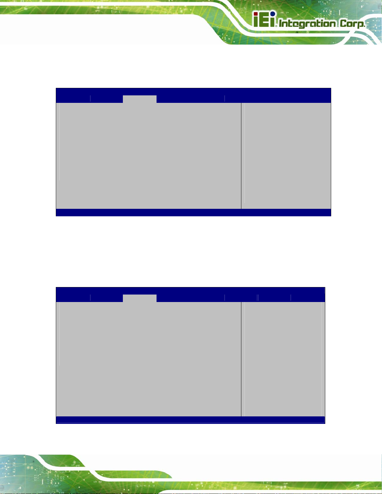
S
PPC-F12B/15B/17B-BTi Panel PC
5.4.1 North Bridge
Use the North Bridge menu (5BIOS Menu 15) to configure the north bridge parameters.
Aptio Setup Utility – Copyright (C) 2013 American Megatrends, Inc.
Chipset
> Intel IGD Configuration
Memory Information
Total Memory 2048 MB (LPDDR3)
DIMM1 2048 MB (LPDDR3)
DIMM2 Not Present
Version 2.16.1242. Copyright (C) 2013 American Megatrends, Inc.
Config Intel IGD Settings
---------------------
: Select Screen
: Select Item
Enter: Select
+/-: Change Opt.
F1: General Help
F2: Previous Values
F3: Optimized Defaults
F4: Save & Exit
ESC: Exit
BIOS Menu 15: North Bridge
5.4.1.1 Intel IGD Configuration
Use the Intel IGD Configuration submenu (BIOS Menu 16) to configure the graphics
settings.
Aptio Setup Utility – Copyright (C) 2013 American Megatrends, Inc.
Chipset
Intel IGD Configuration
Primary Display [Auto]
DVMT Pre-Allocated [256M]
DVMT Total Gfx Mem [Max]
Primary IGFX Boot Display [VBIOS Default]
Version 2.16.1242. Copyright (C) 2013 American Megatrends, Inc.
elect which of IGD/PCI
Graphics device should
be Primary Display.
---------------------
: Select Screen
: Select Item
Enter Select
+ - Change Opt.
F1 General Help
F2 Previous Values
F3 Optimized Defaults
F4 Save & Exit
ESC Exit
BIOS Menu 16: Intel IGD Configuration
Page 75
Page 90

Primary Display [Auto]
Use the Primary Display option to select the display device used by the system when it
boots. Configuration options are listed below.
PPC-F12B/15B/17B-BTi Panel PC
Auto
IGD
PCIe
DVMT Pre-Allocated [256M]
Use the DVMT Pre-Allocated option to specify the amount of system memory that can be
used by the internal graphics device.
64M
128M
256M DEFAULT
512M
DEFAULT
64 MB of memory used by internal graphics device
128 MB of memory used by internal graphics
device
256 MB of memory used by internal graphics
device
512 MB of memory used by internal graphics
device
DVMT Total Gfx Mem [Max]
Use the DVMT Total Gfx Mem option to specify the maximum amount of memory that can
be allocated as graphics memory. Configuration options are listed below.
128MB
256MB
Max D
Primary IGFX Boot Display [VBIOS Default]
Use the Primary IGFX Boot Display option to select the display device used by the
system when it boots. Configuration options are listed below.
VBIOS Default
Page 76
EFAULT
DEFAULT
Page 91

PPC-F12B/15B/17B-BTi Panel PC
CRT
HDMI
LVD S
5.4.2 South Bridge
Use the South Bridge menu (BIOS Menu 17) to configure the south bridge parameters.
Aptio Setup Utility – Copyright (C) 2013 American Megatrends, Inc.
Chipset
Auto Power Button Status [Enable (AT)]
> PCI Express Configuration
Audio Configuration
Audio Controller [Enabled]
USB Configuration
XHCI Mode [Smart Auto]
Version 2.16.1242. Copyright (C) 2013 American Megatrends, Inc.
PCI Express
Configuration settings
---------------------
: Select Screen
: Select Item
Enter Select
+ - Change Opt.
F1 General Help
F2 Previous Values
F3 Optimized Defaults
F4 Save & Exit
ESC Exit
BIOS Menu 17: South Bridge
Audio Controller [Enabled]
Use the Audio Controller BIOS option to enable or disable the High Definition Audio
controller.
Disabled
Enabled DEFAULT
XHCI Mode [Smart Auto]
Use the XHCI Mode BIOS option to configure the USB xHCI (USB 3.0) controller.
Enabled
The High Definition Audio controller is disabled.
The High Definition Audio controller is enabled.
Enable the xHCI controller. USB 3.0 ports behave as
USB 3.0 ports.
Page 77
Page 92
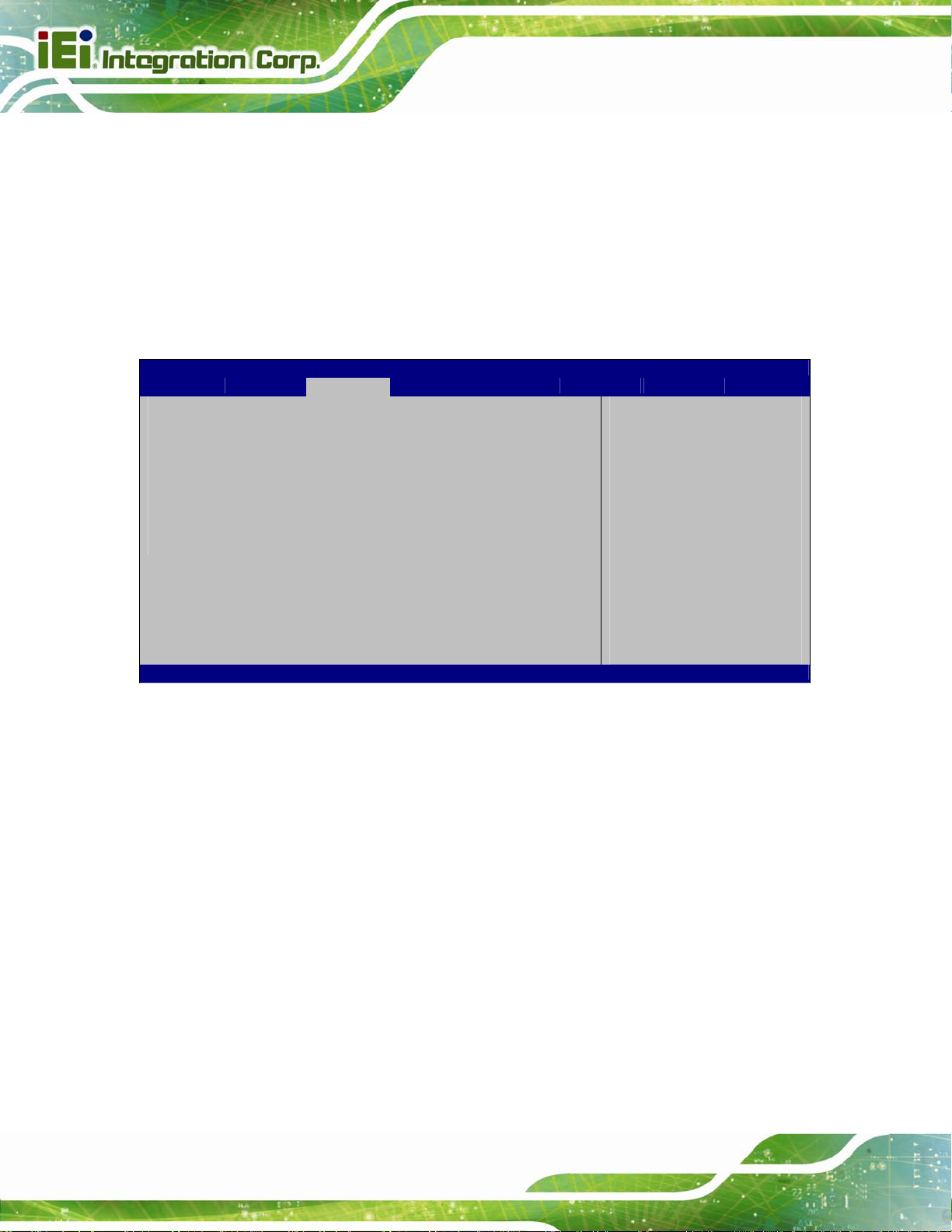
PPC-F12B/15B/17B-BTi Panel PC
Smart
Auto
DEFAULT
Allow the use of USB 3.0 devices prior to OS boot.
USB 3.0 ports function as USB 3.0 ports even during a
reboot.
5.4.2.1 PCI Express Configuration
Use the PCI Express Configuration submenu (BIOS Menu 18) to configure the PCI
Express slots.
Aptio Setup Utility – Copyright (C) 2013 American Megatrends, Inc.
Chipset
PCI Express Configuration
M_PCIE1
Speed [Auto]
PCIE1
Speed [Auto]
Version 2.16.1242. Copyright (C) 2013 American Megatrends, Inc.
Configure PCIe Port
Speed
---------------------
: Select Screen
: Select Item
Enter Select
+ - Change Opt.
F1 General Help
F2 Previous Values
F3 Optimized Defaults
F4 Save & Exit
ESC Exit
BIOS Menu 18: PCI Express Configuration
Speed [Auto]
Use the Speed option to configure the PCIe interface speed.
Page 78
Auto D
Gen 2
Gen 1
EFAULT
Page 93

PPC-F12B/15B/17B-BTi Panel PC
5.5 Security
Use the Security menu (BIOS Menu 19) to set system and user passwords.
Aptio Setup Utility – Copyright (C) 2013 American Megatrends, Inc.
Main Advanced Chipset Security Boot Save & Exit Server Mgmt
Password Description
If ONLY the Administrator’s password is set,
then this only limits access to Setup and is
only asked for when entering Setup.
If ONLY the User’s password is set, then this
is a power on password and must be entered to
boot or enter Setup. In Setup the User will
have Administrator rights.
The password length must be
in the following range:
Minimum length 3
Maximum length 20
Administrator Password
User Password
Version 2.16.1242. Copyright (C) 2013 American Megatrends, Inc.
Set Administrator
Password
---------------------
: Select Screen
: Select Item
Enter: Select
+/-: Change Opt.
F1: General Help
F2: Previous Values
F3: Optimized Defaults
F4: Save & Exit
ESC: Exit
BIOS Menu 19: Security
Administrator Password
Use the Administrator Password to set or change an administrator password.
User Password
Use the User Password to set or change a user password.
Page 79
Page 94

PPC-F12B/15B/17B-BTi Panel PC
5.6 Boot
Use the Boot menu (5BIOS Menu 20) to configure system boot options.
Aptio Setup Utility – Copyright (C) 2013 American Megatrends, Inc.
Main Advanced Chipset Security Boot Save & Exit Server Mgmt
Boot Configuration
Bootup NumLock State [On]
Quiet Boot [Enabled]
UEFI Boot [Disabled]
Launch PXE OpROM [Disabled]
Option ROM Messages [Force BIOS]
Boot Option Priorities
Version 2.16.1242. Copyright (C) 2013 American Megatrends, Inc.
Select the keyboard
NumLock state
---------------------
: Select Screen
: Select Item
Enter: Select
+/-: Change Opt.
F1: General Help
F2: Previous Values
F3: Optimized Defaults
F4: Save & Exit
ESC: Exit
BIOS Menu 20: Boot
Bootup NumLock State [On]
Use the Bootup NumLock State BIOS option to specify if the number lock setting must
be modified during boot up.
On DEFAULT
Off
Allows the Number Lock on the keyboard to be
enabled automatically when the computer system
boots up. This allows the immediate use of the
10-key numeric keypad located on the right side of
the keyboard. To confirm this, the Number Lock LED
light on the keyboard is lit.
Does not enable the keyboard Number Lock
automatically. To use the 10-keys on the keyboard,
press the Number Lock key located on the upper
left-hand corner of the 10-key pad. The Number
Page 80
Lock LED on the keyboard lights up when the
Number Lock is engaged.
Page 95

PPC-F12B/15B/17B-BTi Panel PC
Quiet Boot [Enabled]
Use the Quiet Boot BIOS option to select the screen display when the system boots.
Disabled
Enabled DEFAULT
UEFI Boot [Disabled]
Use the UEFI Boot option to enable or disable to boot from the UEFI devices.
Enabled
Disabled DEFAULT
Launch PXE OpROM [Disabled]
Use the Launch PXE OpROM option to enable or disable boot option for legacy network
devices.
Disabled DEFAULT
Enabled
Normal POST messages displayed
OEM Logo displayed instead of POST messages
Boot from UEFI devices is enabled.
Boot from UEFI devices is disabled.
Ignore all PXE Option ROMs
Load PXE Option ROMs
Option ROM Messages [Force BIOS]
Use the Option ROM Messages option to set the Option ROM display mode.
Force
BIOS
Keep
Current
DEFAULT
Sets display mode to force BIOS.
Sets display mode to current.
Page 81
Page 96

PPC-F12B/15B/17B-BTi Panel PC
5.7 Save & Exit
Use the Save & Exit menu (5BIOS Menu 21) to load default BIOS values, optimal failsafe
values and to save configuration changes.
Aptio Setup Utility – Copyright (C) 2013 American Megatrends, Inc.
Main Advanced Chipset Security Boot Sa Save& Exit Server Mgmt
Save Changes and Reset
Discard Changes and Reset
Restore Defaults
Save as User Defaults
Restore User Defaults
Version 2.16.1242. Copyright (C) 2013 American Megatrends, Inc.
Exit the system after
saving the changes.
---------------------
: Select Screen
: Select Item
Enter: Select
+/-: Change Opt.
F1: General Help
F2: Previous Values
F3: Optimized Defaults
F4: Save & Exit
ESC: Exit
BIOS Menu 21: Save & Exit
Save Changes and Reset
Use the Save Changes and Reset option to save the changes made to the BIOS options
and reset the system.
Discard Changes and Reset
Use the Discard Changes and Reset option to exit the system without saving the
changes made to the BIOS configuration setup program.
Restore Defaults
Use the Restore Defaults option to load the optimal default values for each of the
parameters on the Setup menus. F3 key can be used for this operation.
Save as User Defaults
Page 82
Use the Save as User Defaults option to save the changes done so far as user defaults.
Page 97

PPC-F12B/15B/17B-BTi Panel PC
Restore User Defaults
Use the Restore User Defaults option to restore the user defaults to all the setup options.
5.8 Server Mgmt
Use the Server Mgmt menu (BIOS Menu 22) to configure system event log and BMC
network parameters.
Aptio Setup Utility – Copyright (C) 2013 American Megatrends, Inc.
Main Advanced Chipset Security Boot Save & Exit Server Mgmt
BMC Self Test Status FAILED
BMC Firmware Revision Unknown
> System Event Log
> BMC network configuration
Version 2.16.1242. Copyright (C) 2013 American Megatrends, Inc.
Configure BMC network
parameters
---------------------
: Select Screen
: Select Item
Enter: Select
+/-: Change Opt.
F1: General Help
F2: Previous Values
F3: Optimized Defaults
F4: Save & Exit
ESC: Exit
BIOS Menu 22: Server Mgmt
Page 83
Page 98

C
d
PPC-F12B/15B/17B-BTi Panel PC
5.8.1 System Event Log
Use the System Event Log menu (BIOS Menu 23) to configure system event log options.
Aptio Setup Utility – Copyright (C) 2013 American Megatrends, Inc.
Server Mgmt
Enabling/Disabling Options
SEL Components Disabled[Enabled]
Erasing Settings
Erase SEL [No]
When SEL is Full [Do Nothing]
NOTE: All values changed here do not take effect until
computer is restarted.
Version 2.16.1242. Copyright (C) 2013 American Megatrends, Inc.
hange this to enable or
isable all features of
System Event Logging
during boot.
---------------------
: Select Screen
: Select Item
Enter: Select
+/-: Change Opt.
F1: General Help
F2: Previous Values
F3: Optimized Defaults
F4: Save & Exit
ESC: Exit
BIOS Menu 23: System Event Log
SEL Components [Enabled]
Use the SEL Components option to enable or disable all features of System Event Log
during boot.
Disabled
Enabled DEFAULT
Erase SEL [No]
Use the Erase SEL option to select an option for erasing SEL (system event log).
No DEFAULT
Yes,
On next reset
System Event Log features disabled.
System Event Log features enabled.
Do not erase SEL
Erase SEL on next reset
Page 84
Page 99

S
d
w
PPC-F12B/15B/17B-BTi Panel PC
Yes,
On every reset
When SEL is Full [Do Nothing]
Use the When SEL is Full option to select an option for reaction to a full SEL.
Do Nothing DEFAULT
Erase
Immediately
Erase SEL on every reset
Do nothing when SEL is full
Erase SEL immediately when SEL is full
5.8.2 BMC Network Configuration
Use the BMC Network Configuration menu (5BIOS Menu 24) to configure BMC network
parameters.
Aptio Setup Utility – Copyright (C) 2013 American Megatrends, Inc.
Server Mgmt
BMC network configuration
Lan channel 1
Configuration Address source [Unspecified]
Current Configuration Address sour –
Station IP address –
Subnet mask –
Station MAC address –
Router IP address –
Router MAC address –
Version 2.16.1242. Copyright (C) 2013 American Megatrends, Inc.
BIOS Menu 24: System Event Log
elect to configure LAN
channel parameters
statically or
ynamically (by BIOS or
BMC). Unspecified option
ill not modify any BMC
network parameters
during BIOS phase
---------------------
: Select Screen
: Select Item
Enter: Select
+/-: Change Opt.
F1: General Help
F2: Previous Values
F3: Optimized Defaults
F4: Save & Exit
ESC: Exit
Page 85
Page 100

Configuration Address source [Unspecified]
Use the Configuration Address source to configure LAN channel parameters statically
or dynamically (by BIOS or BMC).
PPC-F12B/15B/17B-BTi Panel PC
Unspecified DEFAULT
Static
DynamicBmcDhcp
DynamicBmcNonDhcp
BMC network parameters will not be
modified during BIOS phase.
Select to modify the following BMC
network parameters:
Station IP address
Subnet mask
Router IP address
Router MAC address
Select to configure LAN channel
parameters dynamically by BMC
running DHCP
Select to configure LAN channel
parameters dynamically by BMC
running other address assignment
protocol
Page 86
 Loading...