

Page 1

PCIE-Q370 Full-size PICMG 1.3 CPU Card
Page i
Full-Size PICMG 1.3 CPU Card Supp or ts L GA1151 8th Gen.
USB 3.1, SATA 6Gb/s, M.2, RS-232, HD Audio and RoHS
Rev. 1.00 – September 21, 2018
MODEL:
PCIE-Q370
Intel® Core™ i7/i5/i3, Pentium® or Celeron® CPU,
Intel® Q370 Chipset, DDR4, VGA, Dual Intel® PCIe GbE,
User Manual
Page 2

PCIE-Q370 Full-size PICMG 1.3 CPU Card
Page ii
Date Version Changes
September 21, 2018 1.00 Initial release
Revision
Page 3

PCIE-Q370 Full-size PICMG 1.3 CPU Card
Page iii
Copyright
COPYRIGHT NOTICE
The information in this document is subject to change without prior notice in order to
improve reliability, design and function and does not represent a commitment on the part
of the manufacturer.
In no event will the manufacturer be liable for direct, indirect, special, incidental, or
consequential damages arising out of the use or inability to use the product or
documentation, even if advised of the possibil ity of such damages.
This document contains proprietary information protected by copyright. All rights are
reserved. No part of this manual may be reproduced by any mechanical, electronic, or
other means in any form without prior written permission of the manufacturer.
TRADEMARKS
All registered trademarks and product names mentioned herein are used for identification
purposes only and may be trademarks and/or registered trademarks of their respective
owners.
Page 4

PCIE-Q370 Full-size PICMG 1.3 CPU Card
Page iv
Manual Conventions
WARNING
Warnings appear where overlooked details may cause damage to the
equipment or result in personal injury. Warnings should be taken
seriously.
CAUTION
Cautionary messages should be heeded to help red uce the chance of
losing data or damaging the product.
NOTE
These messages inform the reader of essent ial but non-critical
information. These messages should be read carefully as any directions
or instructions contained therein can help avoid making mistakes.
Page 5

PCIE-Q370 Full-size PICMG 1.3 CPU Card
Page v
Table of Contents
1 INTRODUCTION .......................................................................................................... 1
1.1 INTRODUCTION ........................................................................................................... 2
1.2 FEATURES ................................................................................................................... 3
1.3 CONNECTORS ............................................................................................................. 4
1.4 DIMENSIONS ............................................................................................................... 5
1.5 DATA FLOW ................................................................................................................ 6
1.6 TECHNICAL SPECIFICATIONS ...................................................................................... 7
2 PACKING LIST ........................................................................................................... 10
2.1 ANTI-STATIC PRECAUTIONS ....................................................................................... 11
2.2 UNPACKING PRECAUTIONS ........................................................................................ 11
2.3 PACKING LIST ........................................................................................................... 12
2.4 OPTIONAL ITEMS ...................................................................................................... 13
3 CONNECTORS ........................................................................................................... 15
3.1 PERIPHERAL INTERFACE CONNECTORS ..................................................................... 16
3.1.1 PCIE-Q370 Layout .......................................................................................... 16
3.1.2 Peripheral Interface Connectors ..................................................................... 17
3.1.3 External Interface Panel Connectors ............................................................... 18
3.2 INTERNAL PERIPHERAL CONNECTORS ...................................................................... 18
3.2.1 +12V ATX Power Connector ........................................................................... 18
3.2.2 Audio Kit Connector ........................................................................................ 19
3.2.3 Battery Connector ............................................................................................ 20
3.2.4 Chassis Intrusion Connector ............................................................................ 21
3.2.5 DDR4 DIMM Sockets ...................................................................................... 22
3.2.6 Digital I/O Connector ...................................................................................... 22
3.2.7 EC Debug Connector ....................................................................................... 23
3.2.8 Fan Connector (CPU) ...................................................................................... 24
3.2.9 Fan Connectors (System) ................................................................................. 25
3.2.10 Front Panel Connector .................................................................................. 25
Page 6

PCIE-Q370 Full-size PICMG 1.3 CPU Card
Page vi
3.2.11 I2C Connector ................................................................................................ 26
3.2.12 Keyboard and Mouse Connector ................................................................... 27
3.2.13 LAN LED Connectors .................................................................................... 28
3.2.1 M.2 2280 Slot, M-Key ...................................................................................... 29
3.2.2 Power Button ................................................................................................... 31
3.2.3 RS-232 Serial Ports .......................................................................................... 31
3.2.4 RS-422/485 Serial Port .................................................................................... 32
3.2.5 SATA 6Gb/s Drive Connector .......................................................................... 33
3.2.6 SMBus Connector ............................................................................................ 34
3.2.7 SPI Flash Connector ........................................................................................ 35
3.2.8 SPI Flash Connector, EC ................................................................................. 36
3.2.9 TPM Connector ................................................................................................ 37
3.2.10 USB 2.0 Connectors ....................................................................................... 38
3.2.11 USB 2.0 Connector (Type A) .......................................................................... 39
3.2.12 USB 3.1 Connector ........................................................................................ 40
3.3 EXTERNAL PERIPHERAL INTERFACE CONNECTOR PANEL ......................................... 41
3.3.1 Ethernet Connectors ........................................................................................ 41
3.3.2 USB 3.1 Gen 1 Connectors .............................................................................. 42
3.3.3 VGA Connector ................................................................................................ 42
4 INSTALLATION ......................................................................................................... 44
4.1 ANTI-STATIC PRECAUTIONS ...................................................................................... 45
4.2 INSTALLATION CONSIDERATIONS .............................................................................. 45
4.3 SOCKET LGA1151 CPU INSTALLATION ................................................................... 47
4.4 SOCKET LGA1151 COOLING KIT INSTALLATION ..................................................... 50
4.5 DIMM INSTALLATION .............................................................................................. 52
4.6 SYSTEM CONFIGURATION ......................................................................................... 53
4.6.1 AT/ATX Power Mode Setting ........................................................................... 53
4.6.2 Clear CMOS Button ......................................................................................... 53
4.6.3 PCIe x16 Channel Mode Setup ........................................................................ 54
4.6.4 Flash Descriptor Security Override Jumper .................................................... 54
4.6.5 USB Power Selection ....................................................................................... 56
4.7 INTERNAL PERIPHERAL DEVICE CONNECTIONS ........................................................ 57
4.7.1 SATA Drive Connection ................................................................................... 57
4.8 SOFTWARE INSTALLATION ........................................................................................ 59
Page 7

PCIE-Q370 Full-size PICMG 1.3 CPU Card
Page vii
4.8.1 Driver Download ............................................................................................. 59
4.9 INTEL
®
AMT SETUP PROCEDURE ............................................................................. 61
5 BIOS .............................................................................................................................. 62
5.1 INTRODUCTION ......................................................................................................... 63
5.1.1 Starting Setup ................................................................................................... 63
5.1.2 Using Setup ...................................................................................................... 63
5.1.3 Getting Help ..................................................................................................... 64
5.1.4 Unable to Reboot after Configuration Changes .............................................. 64
5.1.5 BIOS Menu Bar ................................................................................................ 64
5.2 MAIN ........................................................................................................................ 64
5.3 ADVANCED ............................................................................................................... 66
5.3.1 CPU Configuration .......................................................................................... 67
5.3.2 PCH-FW Configuration ................................................................................... 69
5.3.3 Trusted Computing ........................................................................................... 70
5.3.4 ACPI Settings ................................................................................................... 71
5.3.5 iWDD H/W Monitor ......................................................................................... 72
5.3.5.1 Smart Fan Mode Configuration ................................................................ 73
5.3.6 F81866 Super IO Configuration ...................................................................... 75
5.3.6.1 Serial Port 1 Configuration ....................................................................... 76
5.3.6.2 Serial Port 2 Configuration ....................................................................... 77
5.3.6.3 Serial Port 3 Configuration ....................................................................... 78
5.3.6.4 Serial Port 4 Configuration ....................................................................... 79
5.3.7 RTC Wake Settings ........................................................................................... 80
5.3.8 Serial Port Console Redirection ...................................................................... 81
5.3.8.1 Legacy Console Redirection Settings ....................................................... 84
5.3.9 USB Configuration ........................................................................................... 85
5.3.10 CSM Configuration ........................................................................................ 86
5.3.11 NVMe Configuration ...................................................................................... 87
5.3.12 iEi Feature ..................................................................................................... 88
5.4 CHIPSET ................................................................................................................... 89
5.4.1 System Agent (SA) Configuration .................................................................... 90
5.4.1.1 Memory Configuration ............................................................................. 91
5.4.1.2 Graphics Configuration ............................................................................. 91
5.4.1.3 PEG Port Configuration ............................................................................ 93
Page 8

PCIE-Q370 Full-size PICMG 1.3 CPU Card
Page viii
5.4.2 PCH-IO Configuration .................................................................................... 94
5.4.2.1 PCI Express Configuration ....................................................................... 97
5.4.2.2 SATA Configuration .................................................................................. 99
5.4.2.3 HD Audio Configuration ......................................................................... 101
5.5 SECURITY ............................................................................................................... 102
5.6 BOOT ...................................................................................................................... 103
5.7 SAVE & EXIT .......................................................................................................... 105
A REGULATORY COMPLIANCE ............................................................................ 106
B PRODUCT DISPOSAL ............................................................................................ 108
C BIOS OPTIONS ......................................................................................................... 110
D TERMINOLOGY ...................................................................................................... 114
E DIGITAL I/O INTERFACE ...................................................................................... 118
E.1 INTRODUCTION ....................................................................................................... 119
E.2 ASSEMBLY LANGUAGE SAMPLE 1 .......................................................................... 120
E.3 ASSEMBLY LANGUAGE SAMPLE 2 .......................................................................... 120
F WATCHDOG TIMER ............................................................................................... 121
G HAZARDOUS MATERIALS DISCLOSURE ....................................................... 124
Page 9

PCIE-Q370 Full-size PICMG 1.3 CPU Card
Page ix
List of Figures
Figure 1-1: PCIE-Q370 .................................................................................................................... 2
Figure 1-2: Connectors .................................................................................................................. 4
Figure 1-3: PCIE-Q370 Dimensions (mm ) .................................................................................... 5
Figure 1-4: Data Flow Diagram ...................................................................................................... 6
Figure 3-1: Peripheral Interface Connector s ............................................................................. 16
Figure 3-2: +12V ATX Power Connector Pinout Location ........................................................ 19
Figure 3-3: Audio Connector Location ....................................................................................... 19
Figure 3-4: Battery Connector Location ..................................................................................... 21
Figure 3-5: Chassis Intrusion Connector Location ................................................................... 21
Figure 3-6: DDR4 DIMM Socket Locations ................................................................................. 22
Figure 3-7: Digital I/O Connector Location ................................................................................ 22
Figure 3-8: EC Debug Connector Location ................................................................................ 23
Figure 3-9: CPU Fan Connector Location .................................................................................. 24
Figure 3-10: System Fan Connector Location ........................................................................... 25
Figure 3-11: Front Panel Connector Location ........................................................................... 26
Figure 3-12: I2C Connector Location .......................................................................................... 26
Figure 3-13: Keyboard and Mouse Connector Location ........................................................... 27
Figure 3-14: LAN LED Connector Locations ............................................................................. 28
Figure 3-15: M.2 2280 Slot Location ........................................................................................... 29
Figure 3-16: Power Button Location ........................................................................................... 31
Figure 3-17: RS-232 Serial Port Locations ................................................................................. 31
Figure 3-18: RS-422/485 Serial Port Locations .......................................................................... 32
Figure 3-19: SATA 6Gb/s Drive Connector Locations .............................................................. 33
Figure 3-20: SMBus Connector Location ................................................................................... 34
Figure 3-21: SPI Flash Connector Location ............................................................................... 35
Figure 3-22: SPI EC Flash Connector Location ......................................................................... 36
Figure 3-23: TPM Connector Location ........................................................................................ 37
Figure 3-24: USB 2.0 Connector Locations ............................................................................... 38
Figure 3-25: USB 2.0 Connector (Type A) Pinout Location ...................................................... 39
Figure 3-26: USB 3.1 Connector Location ................................................................................. 40
Page 10

PCIE-Q370 Full-size PICMG 1.3 CPU Card
Page x
Figure 3-27: External Peripheral Interface Co nn ector .............................................................. 41
Figure 3-28: Ethernet Connector ................................................................................................. 41
Figure 3-29: VGA Connector ....................................................................................................... 43
Figure 4-1: Disengage the CPU Socket Load Lev er .................................................................. 47
Figure 4-2: Remove Protective Cover......................................................................................... 48
Figure 4-3: Insert the Socket LGA1151 CPU .............................................................................. 49
Figure 4-4: Close the Socket LGA1151 ...................................................................................... 49
Figure 4-5: Cooling Kit Support Bracket .................................................................................... 51
Figure 4-6: DIMM Installation ....................................................................................................... 52
Figure 4-7: AT/ATX Power Mode Switch Location .................................................................... 53
Figure 4-8: Clear CMOS Button Location ................................................................................... 53
Figure 4-9: Flash Descriptor Security Override Jumper Location .......................................... 54
Figure 4-10: SATA Drive Cable Connection ............................................................................... 57
Figure 4-11: SATA Power Drive Connection .............................................................................. 58
Figure 4-12: IEI Resource Download Center .............................................................................. 59
Page 11

PCIE-Q370 Full-size PICMG 1.3 CPU Card
Page xi
List of Tables
Table 1-1: PCIE-Q370 Specifications ............................................................................................ 9
Table 2-1: Packing List ................................................................................................................. 12
Table 2-2: Optional Items ............................................................................................................. 14
Table 3-1: Peripheral Interface Connectors ............................................................................... 18
Table 3-2: External Peripheral Connectors ................................................................................ 18
Table 3-3: +12V ATX Power Connector Pinouts ........................................................................ 19
Table 3-4: Audio Connector Pinouts .......................................................................................... 20
Table 3-5: Battery Connector Pinouts ........................................................................................ 21
Table 3-6: Chassis Intrusion Connector Pinouts ...................................................................... 21
Table 3-7: Digital I/O Connector Pinouts .................................................................................... 23
Table 3-8: EC Debug Connector Pinouts ................................................................................... 24
Table 3-9: CPU Fan Connector Pinouts...................................................................................... 24
Table 3-10: System Fan (SYS_FAN1) Connector Pinouts ........................................................ 25
Table 3-11: Front Panel Connector Pinouts ............................................................................... 26
Table 3-12: I2C Connector Pinouts .............................................................................................. 27
Table 3-13: Keyboard and Mouse Connector Pinouts .............................................................. 28
Table 3-14: LAN1 LED Connector (LED_LAN1) Pinouts ........................................................... 28
Table 3-15: LAN2 LED Connector (LED_LAN2) Pinouts ........................................................... 28
Table 3-16: M.2 2280 Connector Pinouts ................................................................................... 30
Table 3-17: RS-232 Serial Port Pinouts ...................................................................................... 32
Table 3-18: RS-422/485 Serial Port Pinouts ............................................................................... 32
Table 3-19: DB-9 RS-422/485 Pinouts ......................................................................................... 33
Table 3-20: SATA 6Gb/s Drive Connector Pinouts .................................................................... 34
Table 3-21: SMBus Connector Pinouts ...................................................................................... 34
Table 3-22: SPI Flash Connector Pinouts .................................................................................. 35
Table 3-23: SPI EC Flash Connector Pinouts ............................................................................ 36
Table 3-24: TPM Connector Pinouts ........................................................................................... 37
Table 3-25: USB 2.0 Connector Pinouts ..................................................................................... 38
Table 3-26: USB 2.0 Connector (Type A) Pinouts ..................................................................... 39
Table 3-27: USB 3.1 Connector Pinouts ..................................................................................... 40
Page 12

PCIE-Q370 Full-size PICMG 1.3 CPU Card
Page xii
Table 3-28: LAN Pinouts .............................................................................................................. 41
Table 3-29: USB 3.1 Port Pinouts ................................................................................................ 42
Table 3-30: VGA Connector Pinouts ........................................................................................... 43
Table 4-1: AT/ATX Power Mode Switch Settings ....................................................................... 53
Table 4-2: PCIe x16 Channel Mode Setup .................................................................................. 54
Table 4-3: Flash Descriptor Security Override Jumper Settings ............................................. 54
Table 4-4: BIOS Options and Configured USB Ports ................................................................ 56
Table 4-5: USB Power Source Setup .......................................................................................... 56
Table 5-1: BIOS Navigation Keys ................................................................................................ 64
Table 5-2: BIOS Options and Configured USB Ports ................................................................ 96
Page 13

PCIE-Q370 Full-size PICMG 1.3 CPU Card
Page xiii
BIOS Menus
BIOS Menu 1: Main ....................................................................................................................... 65
BIOS Menu 2: Advanced .............................................................................................................. 66
BIOS Menu 3: CPU Configuration ............................................................................................... 67
BIOS Menu 4: PCH-FW Configuration ........................................................................................ 69
BIOS Menu 5: Trusted Computing .............................................................................................. 70
BIOS Menu 6: ACPI Settings ....................................................................................................... 71
BIOS Menu 7: iWDD H/W Monitor ............................................................................................... 72
BIOS Menu 8: Smart Fan Mode Configuration .......................................................................... 73
BIOS Menu 9: F81866 Super IO Configuration .......................................................................... 75
BIOS Menu 10: Serial Port 1 Configuration Menu ..................................................................... 76
BIOS Menu 11: Serial Port 2 Configuration Menu ..................................................................... 77
BIOS Menu 12: Serial Port 3 Configuration Menu ..................................................................... 78
BIOS Menu 13: Serial Port 4 Configuration Menu ..................................................................... 79
BIOS Menu 14: RTC Wake Settings ............................................................................................ 80
BIOS Menu 15: Serial Port Console Redirection ....................................................................... 81
BIOS Menu 16: Legacy Console Redirection Settings ............................................................. 84
BIOS Menu 17: USB Configuration ............................................................................................. 85
BIOS Menu 18: CSM Configuration ............................................................................................. 86
BIOS Menu 19: NVMe Configuration ........................................................................................... 87
BIOS Menu 20: iEi Feature ........................................................................................................... 88
BIOS Menu 21: Chipset ................................................................................................................ 89
BIOS Menu 22: System Agent (SA) Configuration .................................................................... 90
BIOS Menu 23: Memory Configuration ....................................................................................... 91
BIOS Menu 24: Graphics Configuration ..................................................................................... 91
BIOS Menu 25: PEG Port Configuration ..................................................................................... 93
BIOS Menu 26: PCH-IO Configuration ........................................................................................ 94
BIOS Menu 27: PCI Express Configuration ............................................................................... 97
BIOS Menu 28: PCIEX1 Slot/M.2 Slot .......................................................................................... 97
BIOS Menu 29: SATA Configuration ........................................................................................... 99
BIOS Menu 30: HD Audio Configuration ..................................................................................101
Page 14

PCIE-Q370 Full-size PICMG 1.3 CPU Card
Page xiv
BIOS Menu 31: Security .............................................................................................................102
BIOS Menu 32: Boot ...................................................................................................................103
BIOS Menu 33: Save & Exit ........................................................................................................105
Page 15

PCIE-Q370 Full-size PICMG 1.3 CPU Card
Page 1
Chapter
1
1 Introduction
Page 16

PCIE-Q370 Full-size PICMG 1.3 CPU Card
Page 2
1.1 Introduction
Figure 1-1: PCIE-Q370
The PCIE-Q370 is a full-size PICMG 1.3 CPU card. It accepts a Socket LGA1151 8
generation Intel® Core™ i7/i5/i3, Pentium® or Celeron® processor and supports four
288-pin 2666MHz dual-channel DDR4 DIMM modules up to 64 GB.
The PCIE-Q370 provides two GbE interfaces through the Intel® I219LM (with Intel® AMT
11.0 support) and the Intel® I211AT PCIe controllers. The integrated Intel® Q370 chipset
supports six SATA 6Gb/s drives with RAID 0/1/5/10 function.
Two USB 3.1 on the rear panel, two USB 3.1 by internal box header, six USB 2.0 by pin
headers, one USB 2.0 by internal Type A connector, three RS-232, one RS-422/485 and
one M.2 M-key slot provide flexible expansion options. High Definition Audio (HDA)
support ensures HDA devices can be easily implem ented on the PCIE-Q370.
th
Page 17

PCIE-Q370 Full-size PICMG 1.3 CPU Card
Page 3
1.2 Features
The PCIE-Q370 motherboard features are listed below:
Full-size PICMG 1.3 CPU card
8
Intel® Q370 chipset
Four 288-pin 2666 MHz dual-channel DDR4 DIMMs support up to 64 GB
Two Intel® PCIe GbE connectors (LAN1 with Intel® AMT 11.0 support)
Supports PCI Express Generation 3.0
One M.2 2280 M-key slot for storage
Six SATA 6Gb/s connectors support RAID 0, 1, 5, 10 function
Two USB 3.1 ports on the rear I/O
Two USB 3.1 ports via internal box header
th
generation LGA1151 Intel® Core™ i7/i5/i3, Pentium® or Celeron®
processor supported
Six USB 2.0 ports via internal pin headers
One USB 2.0 via internal Type A connector
Three RS-232 serial ports
One RS-422/485 serial port
TPM V1.2 hardware security function supported by TPM module
High Definition Audio
RoHS compliant
Page 18

PCIE-Q370 Full-size PICMG 1.3 CPU Card
Page 4
1.3 Connectors
The connectors on the PCIE-Q370 are shown in the figure bel ow.
Figure 1-2: Connectors
Page 19
PCIE-Q370 Full-size PICMG 1.3 CPU Card
Page 5
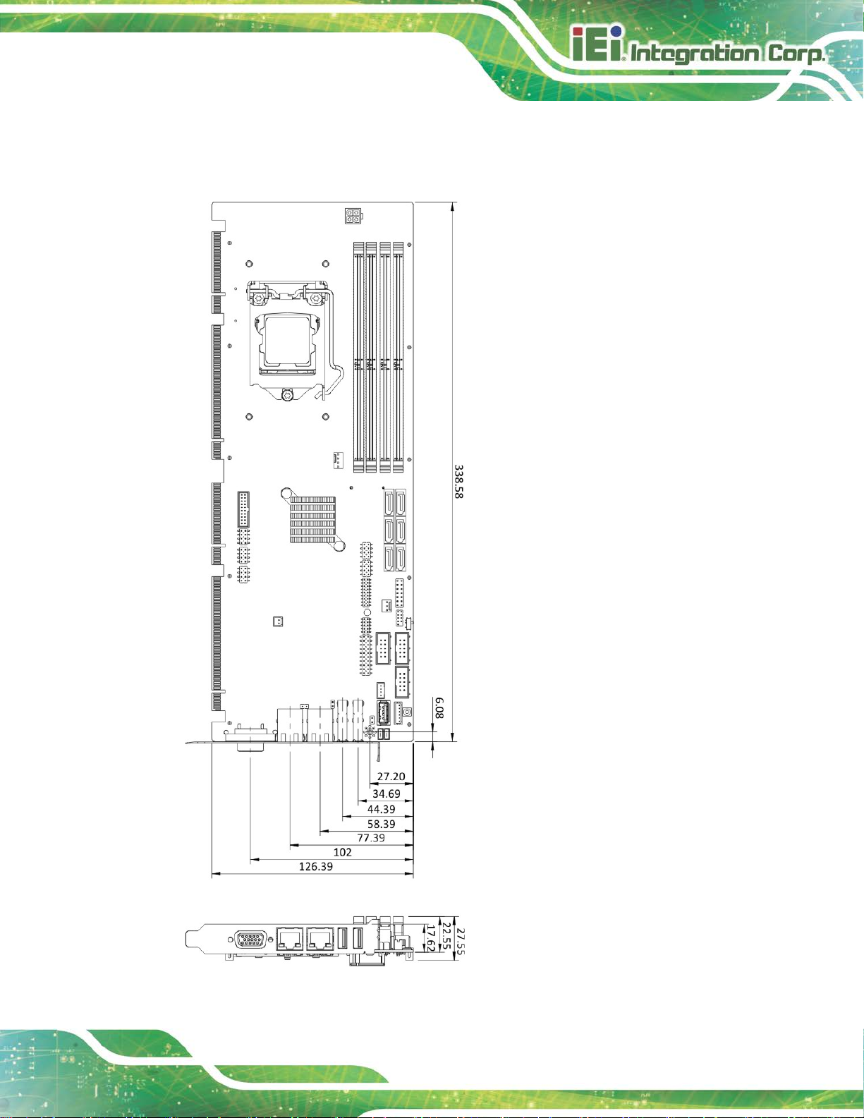
Figure 1-3: PCIE-Q370 Dimensions (mm)
1.4 Dimensions
The main dimensions of the PCIE-Q370 are shown in t he di agram below.
Page 20

PCIE-Q370 Full-size PICMG 1.3 CPU Card
Page 6
1.5 Data Flow
Figure 1-4 shows the data flow between the system chipset, the CPU and other
components installed on the motherboard.
Figure 1-4: Data Flow Diagram
Page 21

PCIE-Q370 Full-size PICMG 1.3 CPU Card
Page 7
1.6 Technical Specifications
The PCIE-Q370 technical specifications are listed below.
Specification/Model PCIE-Q370
Form Factor
CPU Supported
PCH
Memory
Graphics Engine
Display Output
Ethernet Controllers
Audio
Full-size PICMG 1.3 CPU card
8th generation LGA1151 Intel® Core™ i7/i5/i3, Pentium®
or Celeron® CPU
Intel® Q370
Four 288-pin 2666 MHz dual-channel unbuf f ered DDR 4
SDRAM DIMMs supported (system max. 64 GB)
Intel® HD Graphics Gen9 engine with 16 low-power
execution units, supporting DX 2015, OpenGL 5.x and
OpenCL 2.x, ES 2.0
One VGA (via IT6516BFN, up to 1920x1200@60 Hz)
LAN1: Intel® I219LM PCIe GbE controller with Intel® AMT
11.0 support
LAN2: Intel® I211AT PCIe GbE controll er
Supports 7.1-channel HD audio by IEI AC-KIT-892HD kit
BIOS
Expansions
Super I/O Controller
Embedded Controller
Watchdog Timer
UEFI BIOS
One M.2 2280 slot (M key, PCIe x4 only)
4 x PCI link via golden finger
4 x PCIe x1 link via golden finger
16-lane PCIe link from CPU via golden finger:
Supports one PCIe x16, or two PCIe x8, or two PCI e x4 +
one PCIe x8 slots on the backplane (configured via BIOS)
Fintek F81866D-I
ITE IT8528E
Software programmable supports 1~255 sec. system reset
Page 22

PCIE-Q370 Full-size PICMG 1.3 CPU Card
Page 8
I/O Interface Connectors
Audio Connector
Chassis Intrusion
Digital I/O
Ethernet
Fan
Front Panel
I2C
Keyboard and Mouse
LAN LED
Serial ATA
Serial Ports
One audio connector (10-pin header)
One 2-pin header
8-bit digital I/O (10-pin header)
Two RJ-45 p ort s
One 4-pin CPU smart fan connector
One 3-pin system smart fan connector
One 14-pin header (power LED, H DD LED, speaker, power
button, reset button)
One 4-pin wafer connector
One internal keyboard and mouse connector (6-pin wafer)
Two 2-pin headers for LAN1 LED and LAN2 LED
Six SATA 6Gb/s connectors (support RAID 0, 1, 5, 10)
Three RS-232 via internal 10-pin box headers
One RS-422/485 via internal 4-pin wafer
SMBus
TPM
USB 2.0
USB 3.1 Gen 1
Environmental and Power Specifications
Power Supply
Power Consumption
Operating Temperature
Storage Temperature
Operating Humidity
One 4-pin wafer connector
One via 20-pin header
Six USB 2.0 ports by three internal pin headers
One USB 2.0 port by internal Type A connector
Two USB 3.1 ports on rear panel
Two USB 3.1 ports via internal box header
AT/ATX power support
5V@3.12A, 12V@6.85A, 3.3V@1.13A, 5VSB@0.15A
(4.0 GHz Intel® Core™ i7-8700K CPU with four 16 GB
2666 MHz DDR4 memory)
-20ºC ~ 60ºC
-30ºC ~ 70ºC
5% ~ 95% (non-condensing)
Page 23
PCIE-Q370 Full-size PICMG 1.3 CPU Card
Page 9
Physical Specifications
Dimensions
Weight (GW/NW)
Table 1-1: PCIE-Q370 Specifications
338 mm x 126 mm
1000 g/500 g
Page 24

PCIE-Q370 Full-size PICMG 1.3 CPU Card
Page 10
Chapter
2
2 Packing List
Page 25

PCIE-Q370 Full-size PICMG 1.3 CPU Card
Page 11
2.1 Anti-static Precautions
WARNING!
Static electricity can destroy certain elect ronics. Make sur e to follow the
ESD precautions to prevent damage to the product, and injury to the
user.
Make sure to adhere to the following guidelines:
Wear an anti-static wristband: Wearing an anti-static wristband can prevent
electrostatic discharge.
Self-grounding: Touch a grounded conductor every few minutes to discha rge
any excess static buildup.
Use an anti-static pad: When configuring any circuit board, place it on an
anti-static mat.
Only handle the edges of the PCB: Don't touch the surface of the
motherboard. Hold the motherboard by the edges when handling.
2.2 Unpacking Precautions
When the PCIE-Q370 is unpacked, please do the following:
Follow the anti-static guidelines above.
Make sure the packing box is facing upwards when opening.
Make sure all the packing list items are present.
Page 26

PCIE-Q370 Full-size PICMG 1.3 CPU Card
Page 12
2.3 Packing List
NOTE:
If any of the components listed in the checklist below are missing, do
not proceed with the installation. Contact the IEI reseller or vendor the
PCIE-Q370 was purchased from or contact an IEI sales representative
directly by sending an email to sales@ieiworld.com.
The PCIE-Q370 is shipped with the following components:
Quantity Item and Part Number Image
1 PCIE-Q370 CPU card
1 SATA cable
1 Mini jumper pack
1 Quick installation guide
Table 2-1: Packing List
Page 27

PCIE-Q370 Full-size PICMG 1.3 CPU Card
Page 13
2.4 Optional Items
The following are optional components which may be separately purchased:
Item and Part Number Image
PS/2 KB/MS Y-cable with bracket
(P/N: 19800-000075-RS)
SATA power cable
(P/N: 32102-000100-200-RS)
7.1-channel HD audio kit with Realtek ALC892 audio
codec supporting dual audio stream
(P/N: AC-KIT-892HD-R10)
LGA1150 cooler kit (high-performance compatible, 95W)
(P/N: CF-1150SA-R10)
LGA1150 cooler kit (high-performance compatible, 65W)
(P/N: CF-1150SB-R11)
LGA1150 cooler kit (1U chassis compatible, 65W)
(P/N: CF-1150SC-R20)
LGA1150 cooler kit (high-performance compatible, 95W)
(P/N: CF-1150SE-R11)
Page 28

PCIE-Q370 Full-size PICMG 1.3 CPU Card
Page 14
Item and Part Number Image
LGA1150 cooler kit (1U chassis compatible, 54W)
(P/N: CF-1150SF-R10)
SATA to IDE/CompactFlash® converter board
(P/N: SAIDE-KIT01-R10)
Table 2-2: Optional Items
Page 29

PCIE-Q370 Full-size PICMG 1.3 CPU Card
Page 15
Chapter
3
3 Connectors
Page 30

PCIE-Q370 Full-size PICMG 1.3 CPU Card
Page 16
3.1 Peripheral Interface Connectors
This chapter details all the peripheral interface connectors.
3.1.1 PCIE-Q370 Layout
The figure below shows all the peripheral interface connectors.
Figure 3-1: Peripheral Interface Connectors
Page 31

PCIE-Q370 Full-size PICMG 1.3 CPU Card
Page 17
3.1.2 Peripheral Interface Connectors
The table below lists all the connectors on the board.
Connector Type Label
+12V ATX power supply connector
Audio kit connector 10-pin header J_AUDIO1
Battery connector 2-pin wafer BAT1
Chassis intrusion connector 2-pin header CHASSIS1
DDR4 DIMM sockets 288-pin socket
Digital I/O connector 10-pin header DIO1
EC debug connector 18-pin header CN1
Fan connector (CPU) 4-pin wafer CPU_FAN1
Fan connector (system) 3-pin wafer SYS_FAN1
Front panel connector 14-pin header F_PANEL1
4-pin Molex power
CPU12V1
connector
CHA_DIMM0,
CHA_DIMM1,
CHB_DIMM0,
CHB_DIMM1
I2C connector 4-pin wafer I2C1
Keyboard and mouse connector 6-pin wafer KB_MS1
LAN LED connectors 2-pin header LED_LAN1, LED_LAN2
M.2 M-key slot M.2 M-key 2280 M2_M1
Power button Push button PWR_SW1
RS-232 serial ports 10-pin box header
RS-422/485 serial port 4-pin wafer
SATA 6Gb/s drive connector 7-pin SATA connector
SMBus connector 4-pin wafer SMB1
COM1, COM2,
COM3,
COM4
S_ATA1, S_ATA2,
S_ATA3, S_ATA4,
S_ATA5, S_ATA6,
Page 32

PCIE-Q370 Full-size PICMG 1.3 CPU Card
Page 18
Connector Type Label
SPI flash connector 8-pin h eader JSPI1
SPI flash connector, EC 8-pin header JSPI2
TPM connector 20-pin header TPM1
USB 2.0 connectors 8-pin header USB1, USB2, USB4
USB 2.0 connector (Type A) Type A USB3
USB 3.1 connector 19-pin box header USB3-1
Table 3-1: Peripheral Interface Connectors
3.1.3 External Interface Panel Connectors
The table below lists the connectors on the external I /O panel.
Connector Type Label
Ethernet ports RJ-45 LAN1, LAN2
USB 3.1 ports USB 3.1 USB3_1, USB3_2
VGA connector 15-pin female VGA1
Table 3-2: External Peripheral Connectors
3.2 Internal Peripheral Connectors
The section describes all of the connectors on the PCIE-Q370.
3.2.1 +12V A TX Power Connector
CN Label: CPU12V1
CN Type:
CN Location:
CN Pinouts:
4-pin Molex power connector, p=4.2 mm
See Figure 3-2
See Table 3-3
This connector provides power to the CPU.
Page 33

PCIE-Q370 Full-size PICMG 1.3 CPU Card
Page 19
Figure 3-2: +12V ATX Power Connector Pinout Location
Pin Description Pin Description
1 GND 2 GND
3 +12V 4 +12V
Table 3-3: +12V ATX Power Connector Pinouts
3.2.2 Audio Kit Connector
CN Label: J_AUDIO1
CN Type:
CN Location:
CN Pinouts:
This connector allows connection to an external audio kit.
10-pin header, p=2.00 mm
See Figure 3-3
See Table 3-4
Figure 3-3: Audio Connector Location
Page 34

PCIE-Q370 Full-size PICMG 1.3 CPU Card
Page 20
Dispose of used batteries according to instructions and local
It is recommended to attach the RTC battery onto the system chassis
Pin Description Pin Description
1 HDA_SYNC 2 HDA_BIT_CLK
3 HDA_SDOUT 4 HDA_SPKR
5 HDA_SDIN 6 HDA_RST#
7 HDA_VCC 8 HDA_GND
9 HDA_+12V 10 HDA_GND
Table 3-4: Audio Connector Pinouts
3.2.3 Battery Connector
CAUTION:
Risk of explosion if battery is replaced by an incorrect type. Only
certified engineers should replace the on-board battery.
regulations.
NOTE:
in which the PCIE-Q370 is installed.
CN Label: BAT1
CN Type:
CN Location:
CN Pinouts:
This is connected to the system battery. The batt ery provides po wer to the syst em clock to
retain the time when power is turned off.
2-pin wafer, p=1.25 mm
See Figure 3-4
See Table 3-5
Page 35

PCIE-Q370 Full-size PICMG 1.3 CPU Card
Page 21
Figure 3-4: Battery Connector Location
Pin Description
1 VBATT
2 GND
Table 3-5: Battery Connector Pinouts
3.2.4 Chassis Intrusion Connector
CN Label: CHASSIS1
CN Type:
CN Location:
CN Pinouts:
The chassis intrusion connector is for a chassis intrusion detection s ensor or switch that
detects if a chassis component is removed or repl aced.
Figure 3-5: Chassis Intrusion Connector Location
2-pin header, p=2.54 mm
See Figure 3-5
See Table 3-6
Pin Description
1 +3.3VSB
2 CHASSIS OPEN
Table 3-6: Chassis Intrusion Connector Pinouts
Page 36
PCIE-Q370 Full-size PICMG 1.3 CPU Card
Page 22
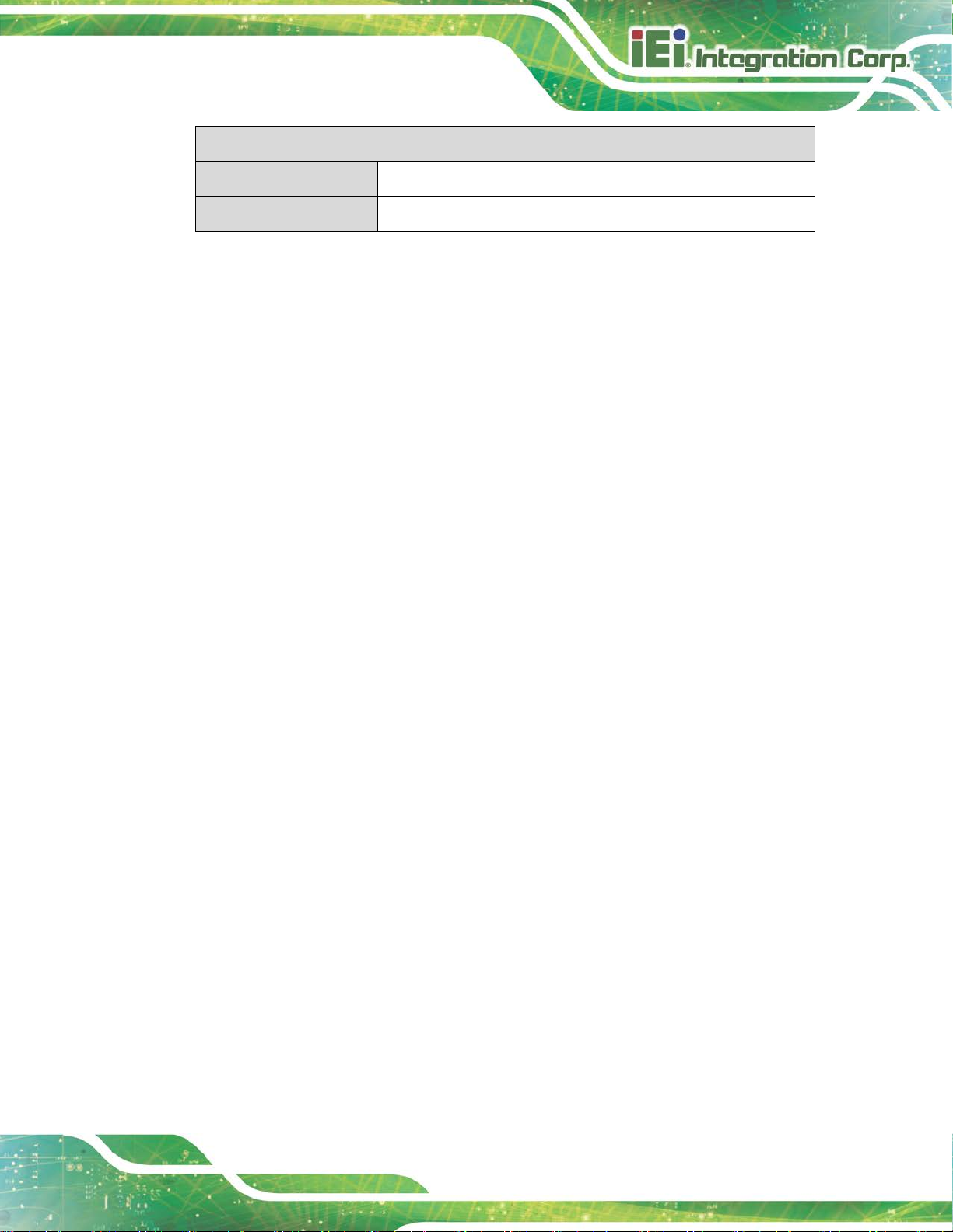
3.2.5 DDR4 DIMM Sockets
CN Label: CHA_DIMM0, CHA_DIMM1, CHB_DIMM0, CHB_DIMM1
CN Type:
CN Location:
The DIMM sockets are for DDR4 DIMM memory modules.
Figure 3-6: DDR4 DIMM Socket Locations
288-pin DDR4 DIMM socket
See Figure 3-6
3.2.6 Digital I/O Connector
CN Label: DIO1
CN Type:
CN Location:
CN Pinouts:
The digital I/O connector provides programmable input and output for external devices.
Figure 3-7: Digital I/O Connector Location
10-pin header, p=2.00 mm
See Figure 3-7
See Table 3-7
Page 37
PCIE-Q370 Full-size PICMG 1.3 CPU Card
Page 23
Pin Description Pin Description
1 GND 2 VCC
3 Output 3 4 Output 2
5 Output 1 6 Output 0
7 Input 3 8 Input 2
9 Input 1 10 Input 0
Table 3-7: Digital I/O Connector Pinouts
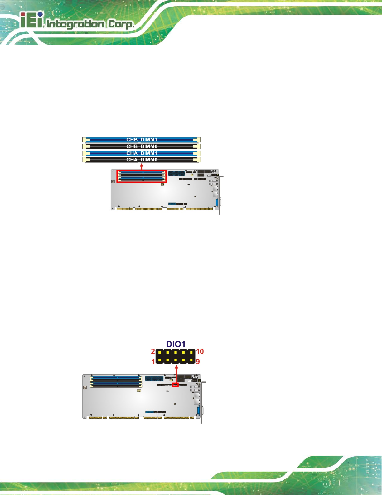
3.2.7 EC Debug Connector
CN Label: CN1
CN Type:
CN Location:
CN Pinouts:
18-pin header, p=2.00 mm
See Figure 3-8
See Table 3-8
The EC debug connector is used for EC debug.
Figure 3-8: EC Debug Connector Location
Pin Description Pin Description
1 EC_EPP_STB# 2 EC_EPP_AFD#
3 EC_EPP_PD0 4 NC
5 EC_EPP_PD1 6 EC_EPP_INIT#
7 EC_EPP_PD2 8 EC_EPP_SLIN#
9 EC_EPP_PD3 10 GND
11 EC_EPP_PD4 12 NC
Page 38
PCIE-Q370 Full-size PICMG 1.3 CPU Card
Page 24
Pin Description Pin Description
13 EC_EPP_PD5 14 EC_EPP_BUSY
15 EC_EPP_PD6 16 EC_EPP_KSI5
17 EC_EPP_PD7 18 EC_EPP_KSI4
Table 3-8: EC Debug Connector Pinouts
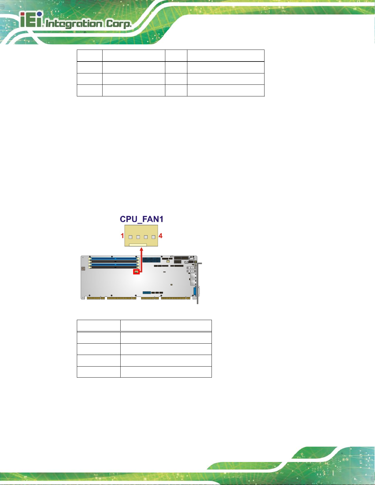
3.2.8 Fan Connector (CPU)
CN Label: CPU_FAN1
CN Type:
CN Location:
CN Pinouts:
4-pin wafer, p=2. 54 m m
See Figure 3-9
See Table 3-9
The fan connector attaches to a CPU cooling fan.
Figure 3-9: CPU Fan Connector Location
Pin Description
1 GND
2 +12V
3 FANIO
4 PWM
Table 3-9: CPU Fan Connector Pinouts
Page 39

PCIE-Q370 Full-size PICMG 1.3 CPU Card
Page 25
3.2.9 Fan Connectors (System)
CN Label: SYS_FAN1
CN Type:
CN Location:
CN Pinouts:
The fan connector attaches to a system cooling fan.
Figure 3-10: System Fan Connector Location
3-pin wafer, p=2. 54 m m
See Figure 3-10
See Table 3-10
Pin Description
1 FANIO
2 +12V (PWM)
3 GND
Table 3-10: System Fan (SYS_FAN1) Connector Pinouts
3.2.10 Front Panel Connector
CN Label: F_PANEL1
CN Type:
CN Location:
CN Pinouts:
The front panel connector connects to the indicator LEDs and buttons on the computer's
front panel.
14-pin header, p=2.54 mm
See Figure 3-11
See Table 3-11
Page 40

PCIE-Q370 Full-size PICMG 1.3 CPU Card
Page 26
Figure 3-11: Front Panel Connector Location
Function Pin Description Function Pin Description
1 PWR_LED+ Speaker 2 SPKR+
Power LED
Power Button
HDD LED
3 NC
5 PWR_LED- 6 NC
7 PWR_BTN+ Speaker 8 SPKR9 PWR_BTN- 10 NC
11 HDD_LED+
13 HDD_LED- 14 Reset-
Table 3-11: Front Panel Connector Pinouts
3.2.11 I2C Connector
CN Label: I2C1
CN Type:
CN Location:
CN Pinouts:
2
C connector is used to connect I2C-bus devices to the motherboard.
The I
4-pin wafer, p=1. 25 m m
See Figure 3-12
See Table 3-12
IPMI LED
4 NC
12 Reset+
Reset
Figure 3-12: I2C Connector Location
Page 41

PCIE-Q370 Full-size PICMG 1.3 CPU Card
Page 27
Pin Description
1 GND
2 I2C_DAT
3 I2C_CLK
4 +5V
Table 3-12: I2C Connector Pinouts
3.2.12 Keyboard and Mouse Connector
CN Label: KB_MS1
CN Type:
CN Location:
CN Pinouts:
6-pin wafer, p=2.00 mm
See Figure 3-13
See Table 3-13
The keyboard and mouse connector connects to a PS/2 Y-cable that can be connected to
a PS/2 keyboard and mouse.
Figure 3-13: Keyboard and Mouse Connector Location
Pin Description
1 VCC
2 Mouse Data
3 Mouse Clock
4 Keyboard Data
Page 42

PCIE-Q370 Full-size PICMG 1.3 CPU Card
Page 28
Figure 3-14: LAN LED Connector Locations
Pin Description
5 Keyboard Clock
6 GND
Table 3-13: Keyboard and Mouse Connector Pinouts
3.2.13 LAN LED Connectors
CN Label: LED_LAN1, LED_LAN2
CN Type:
CN Location:
CN Pinouts:
2-pin header, p=2.54 mm
See Figure 3-14
See Table 3-14 and Table 3-15
The LAN LED connectors are used to c onnect t o the LAN LE D indicat ors on the c hassis to
indicate users the link activities of the two LAN ports.
Pin Description
1 +3.3V
2 LAN1_LED_LINK#_ACT
Table 3-14: LAN1 LED Connector (LED_LAN1) Pinouts
Pin Description
1 +3.3V
2 LAN2_LED_LINK#_ACT
Table 3-15: LAN2 LED Connector (LED_LAN2) Pinouts
Page 43

PCIE-Q370 Full-size PICMG 1.3 CPU Card
Page 29
3.2.1 M.2 2280 Slot, M-Key
CN Label: M2_M1
CN Type:
CN Location:
CN Pinouts:
M.2 2280 M-key slot
See Figure 3-15
See Table 3-16
The M.2 2280 slot is keyed in the M position. The M.2 slot supports PCIe x4 interfaces.
Figure 3-15: M.2 2280 Slot Location
Pin Description Pin Description
1 GND 2 +3.3V
3 GND 4 +3.3V
5 PCIE_RXN3 6 N/C
7 PCIE_RXP3 8 N/C
9 GND 10 DAS/DSS#
11 PCIE_TXN3 12 +3.3V
13 PCIE_TXP3 14 +3.3V
15 GND 16 +3.3V
17 PCIE_RXN2 18 +3.3V
19 PCIE_RXP2 20 N/C
21 GND 22 N/C
23 PCIE_TXN2 24 N/C
25 PCIE_TXP2 26 N/C
Page 44

PCIE-Q370 Full-size PICMG 1.3 CPU Card
Page 30
Pin Description Pin Description
27 GND 28 N/C
29 PCIE_RXN1 30 N/C
31 PCIE_RXP1 32 N/C
33 GND 34 N/C
35 PCIE_TXN1 36 N/C
37 PCIE_TXP1 38 DEVSLP
39 GND 40 N/C
41 PCIE_RXN0 42 N/C
43 PCIE_RXP0 44 N/C
45 GND 46 N/C
47 PCIE_TXN0 48 N/C
49 PCIE_TXP0 50 PERST#
51 GND 52 CLKREQ#
53 REFCLKN 54 PEWAKE
55 REFCLKP 56 N/C
57 GND 58 N/C
59 Notch 60 Notch
61 Notch 62 Notch
63 Notch 64 Notch
65 Notch 66 Notch
67 N/C 68 SUSCLK
69 PEDET 70 +3.3V
71 GND 72 +3.3V
73 GND 74 +3.3V
75 GND
Table 3-16: M.2 2280 Connector Pinouts
Page 45

PCIE-Q370 Full-size PICMG 1.3 CPU Card
Page 31
Figure 3-17: RS-232 Serial Port Locations
3.2.2 Power Button
CN Label: PWR_SW1
CN Type:
CN Location:
The on-board power button controls system power.
Figure 3-16: Power Button Location
Push button
See Figure 3-16
3.2.3 RS-232 Serial Ports
CN Label: COM1, COM2, COM3
CN Type:
CN Location:
CN Pinouts:
Each of these connectors provides RS-232 conne ct i ons.
10-pin box header, p=2.54 mm
See Figure 3-17
See Table 3-17
Page 46

PCIE-Q370 Full-size PICMG 1.3 CPU Card
Page 32
Pin Description Pin Description
1 DCD 2 DSR
3 RXD 4 RTS
5 TXD 6 CTS
7 DTR 8 RI
9 GND 10 GND
Table 3-17: RS-232 Serial Port Pinouts
3.2.4 RS-422/485 Serial Port
CN Label: COM4
CN Type:
CN Location:
CN Pinouts:
4-pin wafer, p=2.00 mm
See Figure 3-18
See Table 3-18
Each of these connectors provides RS-422/485 connections.
Figure 3-18: RS-422/485 Serial Port Locations
PIN NO. DESCRIPTION
1 RXD4222 RXD422+
3 TXD422+/TXD485+
4 TXD422-/TXD485-
Table 3-18: RS-422/485 Serial Port Pinouts
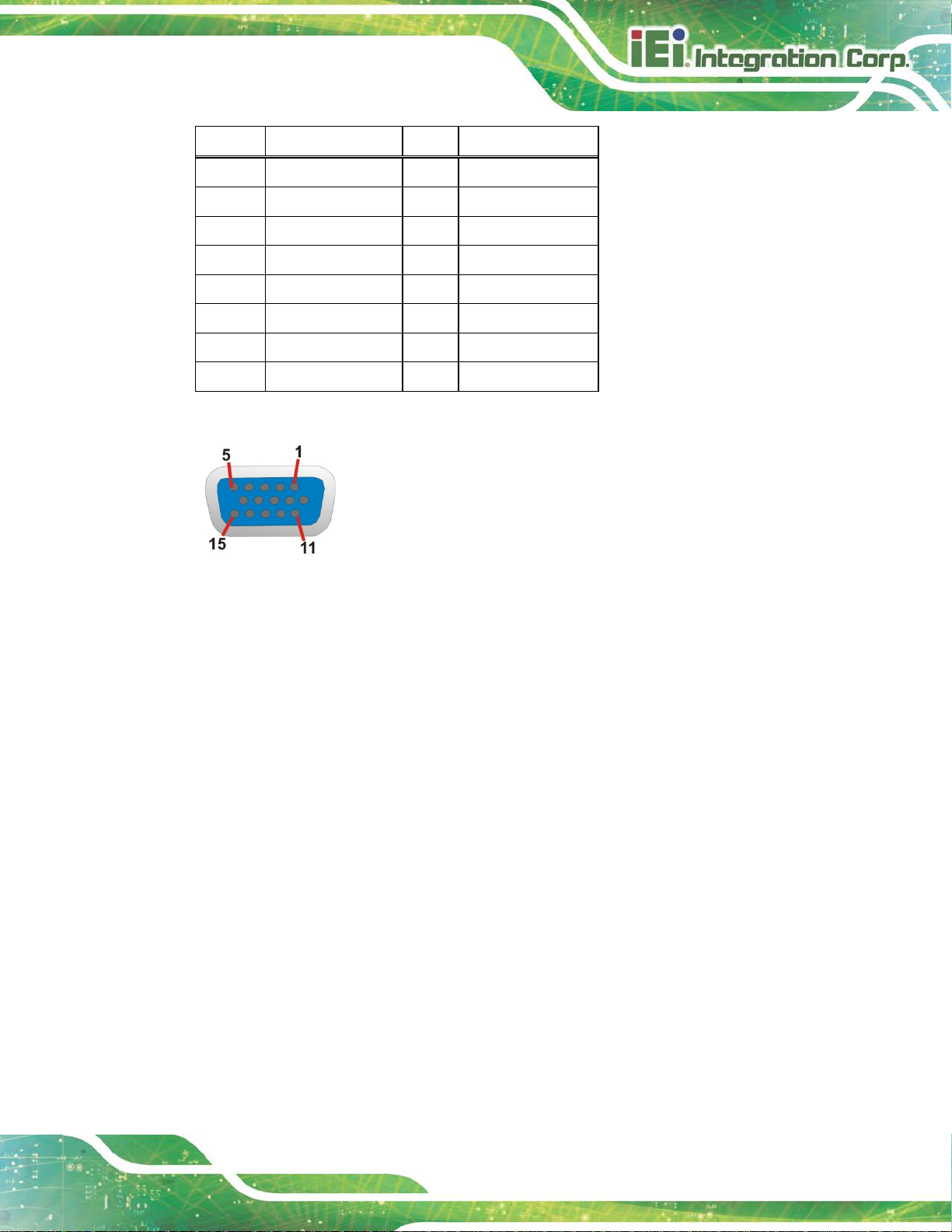
Use the optional RS-422/485 cable to connect to a serial device. The pinouts of the
D-sub 9 connector are listed below.
Page 47

PCIE-Q370 Full-size PICMG 1.3 CPU Card
Page 33
RS-422 Pinouts RS-485 Pinouts
Table 3-19: DB-9 RS-422/485 Pinouts
3.2.5 SATA 6Gb/s Drive Connector
CN Label: S_ATA1, S_ATA2, S_ATA3, S_ATA4, S_ATA5, S_ATA6
CN Type:
CN Location:
CN Pinouts:
The SATA drive connectors can be connected to SATA drives and supports up to 6Gb/s
data transfer rate.
7-pin SATA drive connector
See Figure 3-19
See Table 3-20
Figure 3-19: SATA 6Gb/s Drive Connector Locations
Page 48

PCIE-Q370 Full-size PICMG 1.3 CPU Card
Page 34
Pin Description Pin Description
1 GND 2 TX+
3 TX- 4 GND
5 RX- 6 RX+
7 GND
Table 3-20: SATA 6Gb/s Drive Connector Pinouts
3.2.6 SMBus Connector
CN Label: SMB1
CN Type:
CN Location:
CN Pinouts:
The SMBus (System Management Bus) connector provides low-speed system
management communications.
4-pin wafer, p=1. 25 m m
See Figure 3-20
See Table 3-21
Figure 3-20: SMBus Connector Location
Pin Description
1 GND
2 SMB_DATA
3 SMB_CLK
4 +5V
Table 3-21: SMBus Connector Pinouts
Page 49
PCIE-Q370 Full-size PICMG 1.3 CPU Card
Page 35
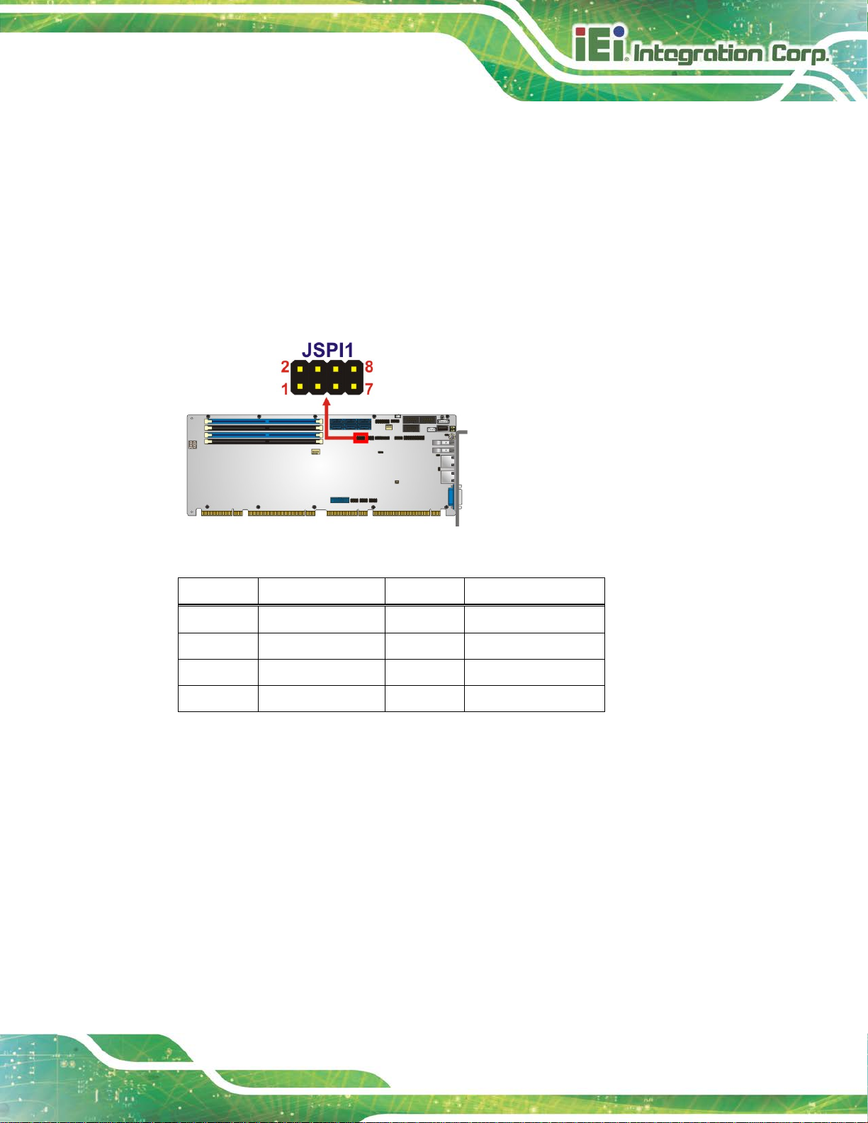
3.2.7 SPI Flash Connector
CN Label: JSPI1
CN Type:
CN Location:
CN Pinouts:
The SPI flash connector is used to flash the SPI ROM.
Figure 3-21: SPI Flash Connector Location
8-pin header, p=2.54 mm
See Figure 3-21
See Table 3-22
Pin Description Pin Description
1 +3.3V 2 GND
3 SPI_CS 4 SPI_CLK_SW
5 SPI_SO_SW 6 SPI_SI_SW
7 NC 8 NC
Table 3-22: SPI Flash Connector Pinouts
Page 50

PCIE-Q370 Full-size PICMG 1.3 CPU Card
Page 36
3.2.8 SPI Flash Connector, EC
CN Label: JSPI2
CN Type:
CN Location:
CN Pinouts:
The SPI flash connector is used to flash the EC ROM.
Figure 3-22: SPI EC Flash Connector Location
8-pin header, p=2.54 mm
See Figure 3-22
See Table 3-23
Pin Description Pin Description
1 +3.3V 2 GND
3 SPI_CS_EC 4 SPI_CLK_EC
5 SPI_SO_EC 6 SPI_SI_EC
7 NC 8 NC
Table 3-23: SPI EC Flash Connector Pinouts
Page 51
PCIE-Q370 Full-size PICMG 1.3 CPU Card
Page 37
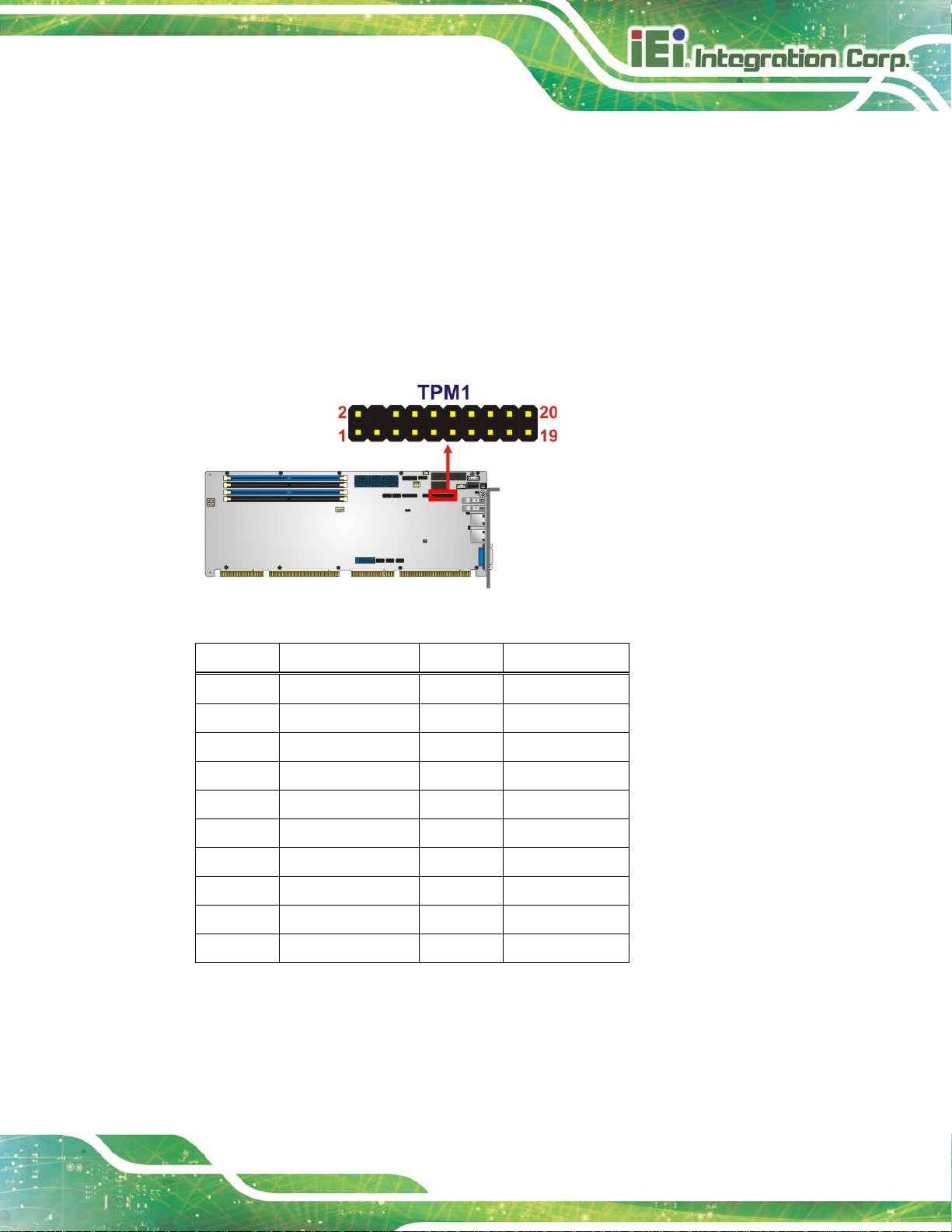
3.2.9 TPM Connector
CN Label: TPM1
CN Type:
CN Location:
CN Pinouts:
20-pin header, p=2.54 mm
See Figure 3-23
See Table 3-24
The TPM connector connects to a TPM module.
Figure 3-23: TPM Connector Location
Pin Description Pin Description
1 LCLK 2 GND
3 LFRAME# 4 KEY
5 LRERST# 6 +5V
7 LAD3 8 LAD2
9 +3.3V 10 LAD1
11 LAD0 12 GND
13 SCL 14 SDA
15 SB3V 16 SERIRQ
17 GND 18 GLKRUN#
19 LPCPD# 20 LDRQ#
Table 3-24: TPM Connector Pinouts
Page 52

PCIE-Q370 Full-size PICMG 1.3 CPU Card
Page 38
3.2.10 USB 2.0 Connectors
CN Label: USB1, USB2, USB4
CN Type:
CN Location:
CN Pinouts:
The USB 2.0 connectors connect to USB 2.0 devices. Each pin header provides two USB
2.0 ports.
Figure 3-24: USB 2.0 Connector Locations
8-pin header, p=2.54 mm
See Figure 3-24
See Table 3-25
Pin Description Pin Description
1 VCC 2 GND
3 USB_DATA- 4 USB_DATA+
5 USB_DATA+ 6 USB_DATA7 GND 8 VCC
Table 3-25: USB 2.0 Connector Pinouts
Page 53
PCIE-Q370 Full-size PICMG 1.3 CPU Card
Page 39
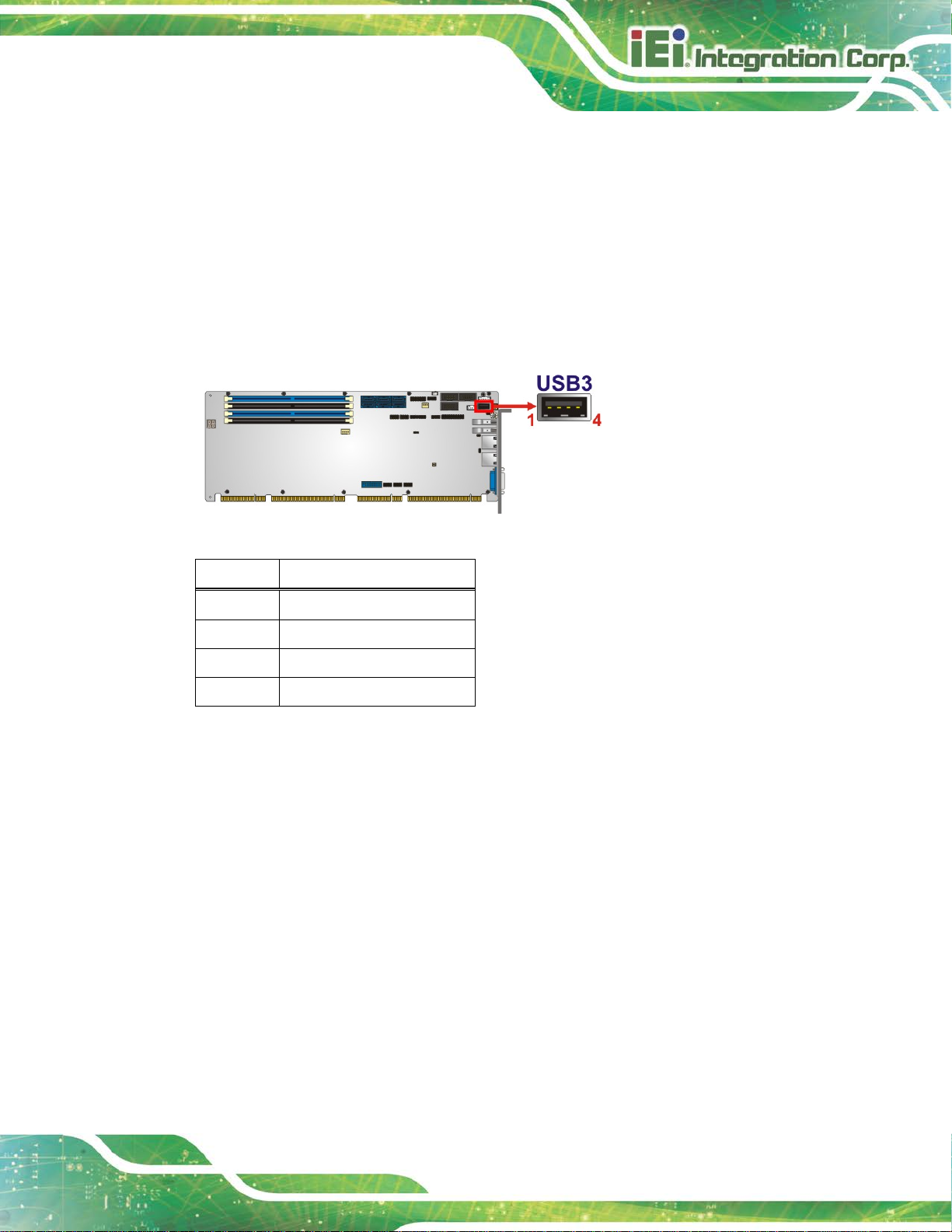
3.2.11 USB 2.0 Connector (Type A)
CN Label: USB3
CN Type:
CN Location:
CN Pinouts:
The USB Type A connector connects to a USB 2.0/1.1 device.
Figure 3-25: USB 2.0 Connector (Type A) Pinout Location
USB Type A
See Figure 3-25
See Table 3-26
Pin Description
1 VCC
2 DATA3 DATA+
4 GROUND
Table 3-26: USB 2.0 Connector (Type A) Pinouts
Page 54
PCIE-Q370 Full-size PICMG 1.3 CPU Card
Page 40
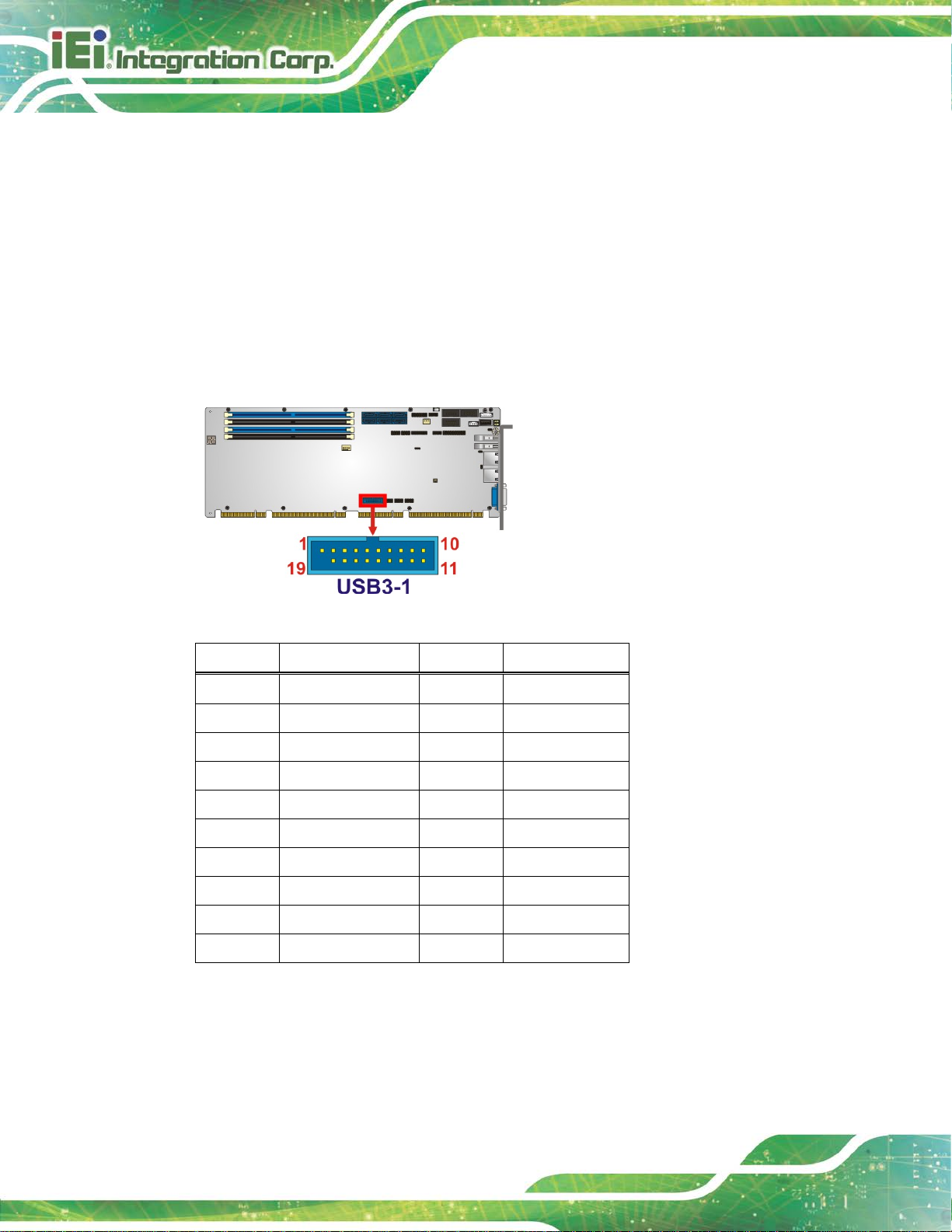
3.2.12 USB 3.1 Connector
CN Label: USB3-1
CN Type:
CN Location:
CN Pinouts:
19-pin box header, p=2.00 mm
See Figure 3-26
See Table 3-27
The USB 3.1 Gen 1 connector connects to USB 3.1 devices. This connector provides two
USB 3.1 Gen 1 ports.
Figure 3-26: USB 3.1 Connector Location
Pin Description Pin Description
1 VCC 11 USB_DATA+
2 USB3_RX- 12 USB_DATA3 USB3_RX+ 13 GND
4 GND 14 USB3_TX+
5 USB3_TX- 15 USB3_TX6 USB3_TX+ 16 GND
7 GND 17 USB3_RX+
8 USB_DATA- 18 USB3_RX9 USB_DATA+ 19 VCC
10 NC
Table 3-27: USB 3.1 Connector Pinouts
Page 55

PCIE-Q370 Full-size PICMG 1.3 CPU Card
Page 41
Figure 3-28: Ethernet Connector
3.3 External Peripheral Interface Connector Panel
The figure below shows the external peripheral interface connector (EPIC) panel. The
EPIC panel consists of the following:
Figure 3-27: External Peripheral Interface Connector
3.3.1 Ethernet Connectors
CN Label: LAN1, LAN2
CN Type:
CN Location:
CN Pinouts:
Each LAN connector connects to a local network.
Pin Description Pin Description
1 LAN_MDI0P 5 LAN_MDI2P
2 LAN_MDI0N 6 LAN_MDI2N
3 LAN_MDI1P 7 LAN_MDI3P
4 LAN_MDI1N 8 LAN_MDI3N
Table 3-28: LAN Pinouts
RJ-45
See Figure 3-27
See Table 3-28
Page 56

PCIE-Q370 Full-size PICMG 1.3 CPU Card
Page 42
The user has to connect the VGA connector to the monitor before
3.3.2 USB 3.1 Gen 1 Connectors
CN Label: USB3_1, USB3_2
CN Type:
CN Location:
CN Pinouts:
There are two external USB 3.1 Gen 1 connectors on the PCIE-Q370.
Pin Description Pin Description
1 VBUS 2 D3 D+ 4 GND
5 STDA_SSRX_N 6 STDA_SSRX_P
7 GND_DRAIN 8 STDA_SSTX_N
9 STDA_SSTX_P
Table 3-29: USB 3.1 Port Pinouts
USB 3.1
See Figure 3-27
See Table 3-29
3.3.3 VGA Connector
CN Label: VGA1
CN Type:
CN Location:
CN Pinouts:
The 15-pin VGA connector connects to a monit or that accepts a standard VGA input.
15-pin VGA
See Figure 3-27
See Table 3-30
NOTE:
system booting as the VGA output function is supported via the eDP to
VGA converter.
Page 57
PCIE-Q370 Full-size PICMG 1.3 CPU Card
Page 43
Pin Description Pin Description
1 RED 2 GREEN
3 BLUE 4 NC
5 GND 6 HOT PLUG DETECT
7 GND 8 GND
9 VCC 10 GND
11 NC 12 DDCDA
13 HSYNC 14 VSYNC
15 DDCCLK
Table 3-30: VGA Connector Pinouts
Figure 3-29: VGA Connector
Page 58

PCIE-Q370 Full-size PICMG 1.3 CPU Card
Page 44
Chapter
4
4 Installation
Page 59

PCIE-Q370 Full-size PICMG 1.3 CPU Card
Page 45
Failure to take ESD precautions during the installation of the
4.1 Anti-static Precautions
WARNING:
PCIE-Q370 may result in permanent damage to the PCIE-Q370 and
severe injury to the user.
Electrostatic discharge (ESD) can cause serious damage to electronic components,
including the PCIE-Q370. Dry climates are especially susceptible to ESD. It is therefore
critical that whenever the PCIE-Q370 or any other electrical component is handled, the
following anti-static precautions are strictly adhered to.
Wear an anti-static wristband: - Wearing a simple anti-static wristband can
help to prevent ESD from damaging the board.
Self-grounding:- Before handling the board touch an y grounded conducting
material. During the time the board is handled, f requently touch any
conducting materials that are connected to the ground.
Use an anti-static pad: When configuring the PCIE-Q370, place it on an
anti-static pad. This reduces the possibility of ESD damaging the PCIE-Q370.
Only handle the edges of the PCB:-: When handling t he PCB, h old t he P CB
by the edges.
4.2 Installation Considerations
NOTE:
The following installation notices and installation c onsiderations should
be read and understood before installation. All instal l ation notices must
be strictly adhered to. Failing to adhere to these precautions may lead
to severe damage and injury to the person performing the installation.
Page 60

PCIE-Q370 Full-size PICMG 1.3 CPU Card
Page 46
The installation instructions described in this manual should be
WARNING:
carefully followed in order to prevent damage to the components and
injury to the user.
Before and during the installation please DO the following:
Read the user manual:
o The user manual provides a complete description of the PCIE-Q370
installation instructions and configuration opt i ons.
Wear an electrostatic discharge cuff (ESD):
o Electronic components are easily damaged by ESD. Wearing an E SD cuff
removes ESD from the body and helps prevent ESD damage.
Place the PCIE-Q370 on an anti-static pad:
o When installing or configuring the motherboa rd, pl ace it on an anti-static
pad. This helps to prevent potential ESD damage.
Turn all power to t he PCIE-Q370 off:
o When working with the PCIE-Q370, make sure that it i s disconnected
from all power supplies and that no elect ricity is b eing f ed into the sy stem.
Before and during the installation of the PCIE-Q370, DO NOT :
Remove any of the stickers on the PCB board. These stickers a re requir ed for
warranty validation.
Use the product before verifying all the cables and power connectors are
properly connected.
Allow screws to come in contact with the PCB circuit, connector pins, or its
components.
Page 61

PCIE-Q370 Full-size PICMG 1.3 CPU Card
Page 47
is installed properly and ensure the correct cooling kit is properly
4.3 Socket LGA1151 CPU Installation
WARNING:
CPUs are expensive and sensitive components. When installing the
CPU please be careful not to damage it in anyway. Make sur e the CPU
installed.
DO NOT touch the pins at the bottom of the CPU. When handling the
CPU, only hold it on the sides.
To install the CPU, follow the steps below.
Step 1: Disengage the load lever by pressing the lever down and slightly outward to
clear the retention tab. Fully open the lever. See Figure 4-1.
Figure 4-1: Disengage the CPU Socket Load Lev er
Step 2: Open the socket and remove the protective cover. The black protective
cover can be removed by pulling up on the tab labeled "Remove". See
Figure 4-2.
Page 62

PCIE-Q370 Full-size PICMG 1.3 CPU Card
Page 48
DO NOT touch the pins at the bottom of the CPU. When handling the
Figure 4-2: Remove Protective Cover
Step 3: Inspect the CPU socket. Make sure there are no bent pins and make sure the
socket contacts are free of foreign material. I f any debris is foun d, rem ove i t wit h
compressed air .
Step 4: Orientate the CPU properly. The contact array should be facing the CPU
socket.
WARNING:
CPU, only hold it on the sides.
Step 5: Correctly position the CPU. Match the Pin 1 mark with the cut edge on the
CPU socket.
Step 6: Align the CPU pins. Locate pin 1 and the two orientation notc hes on the CPU.
Carefully match the two orientation notc hes on the CPU with the socket
alignment keys.
Page 63

PCIE-Q370 Full-size PICMG 1.3 CPU Card
Page 49
Step 7: Insert the CPU. Gently insert the CPU into the socket. If the CPU pins are
properly aligned, the CPU should slide into the CPU socket smoothly. See
Figure 4-3.
Figure 4-3: Insert the Socket LGA1151 CPU
Step 8: Close the CPU socket. Close the load plate and pull the load lever back a little
to have the load plate be able to secure to the knob. E ngage the load lever by
pushing it back to its original position (Figure 4-4). There will be some
resistance, but will not require extreme pressure.
Figure 4-4: Close the Socket LGA1151
Page 64

PCIE-Q370 Full-size PICMG 1.3 CPU Card
Page 50
installed support bracket prevents the board from
sprayed layer of
sink. The thermal paste
between the CPU and the heat sink is important for optimum heat
Step 9: Connect the 12 V power to the board. Connect the 12 V power fr om the power
supply to the board. Step 0:
4.4 Socket LGA1151 Cooling Kit Installation
WARNING:
DO NOT attempt to install a push-pin cooling fan.
The prebending and is ONLY compatible with captive screw type cooling
fans.
The cooling kit can be bought from IEI. The cool ing kit has a heat sink and fan.
WARNING:
Do not wipe off (accidentally or otherwise) the prethermal paste on the bottom of the heat
dissipation.
To install the cooling kit, follow the instructions below.
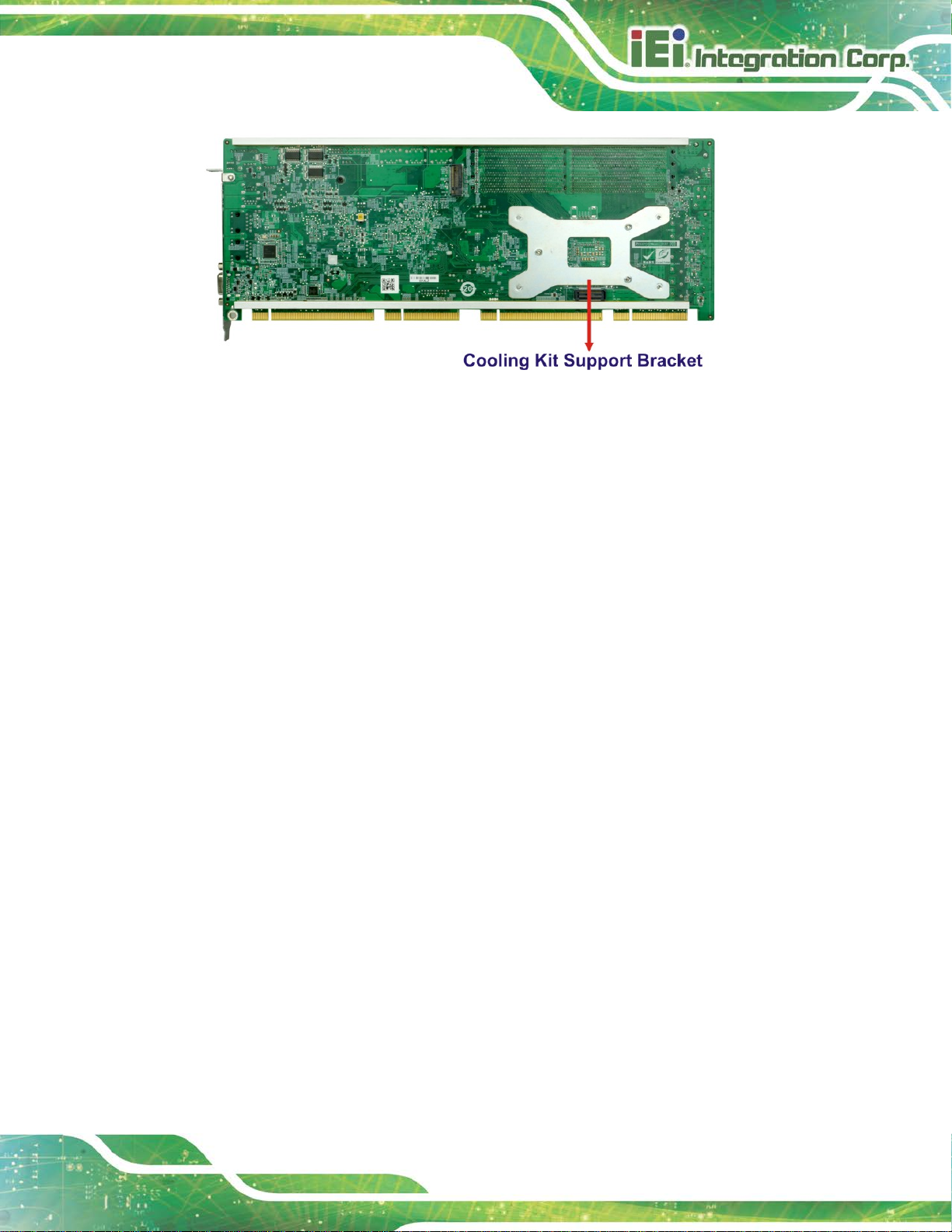
Step 1: A cooling kit bracket is pre-installed on the rear of the motherboard. See Figure 4-5.
Page 65
PCIE-Q370 Full-size PICMG 1.3 CPU Card
Page 51
Figure 4-5: Cooling Kit Support Bracket
Step 2: Place the cooling kit onto the socket LGA1151 CPU. Make sure the CPU
cable can be properly routed when the cooling kit i s installed.
Step 3: Mount the cooling kit. Gently place the cooling kit on top of the CPU. Make
sure the four threaded screws on the corners of the cooling kit properly pass
through the holes of the cooling kit bracket.
Step 4: Tighten the screws. Use a screwdriver to ti ghten the four screws. In a diagonal
pattern, tighten each screw a few turns then move to the next one, until they are
all secured. Do not overtighten the screws.
Step 5: Connect the fan cable. Connect the cooling kit fan cable to the CPU fan
connector on the PCIE-Q370. Carefully route the cable and avoid heat
generating chips and fan blades.Step 0:
Page 66

PCIE-Q370 Full-size PICMG 1.3 CPU Card
Page 52
that feature the same capacity, timings, voltage, number of ranks and
4.5 DIMM Installation
To install a DIMM, please follow the steps below and refer to Figure 4-6.
Figure 4-6: DIMM Installation
Step 1: Open the DIMM socket handles. Open the two handles outwards as far as
they can. See Figure 4-6.
Step 2: Align the DIMM with the socket. Align the DIMM so the notch on the memory
lines up with the notch on the memory socket. See Figure 4-6.
Step 3: Insert the DIMM. Once aligned, press down until the DIMM i s properly seated.
Clip the two handles into place. See Figure 4-6.
Step 4: Removing a DIMM. To remove a DIMM, push both handles o utward. The
memory module is ejected by a mechanism in the socket.Step 0:
CAUTION:
For quad channel configuration, install four identic al memory modules
the same brand.
Page 67

PCIE-Q370 Full-size PICMG 1.3 CPU Card
Page 53
4.6 System Configuration
The system configuration should be performed before installation.
4.6.1 AT/ATX Power Mode Setting
The AT and ATX power mode selection is made through the AT/ATX power mod e switc h
which is shown in Figure 4-7.
Figure 4-7: AT/ATX Power Mode Switch Location
Setting Description
1-2 (right) ATX power mode (default)
2-3 (left) AT power mode
Table 4-1: AT/ATX Power Mode Switch Settings
4.6.2 Clear CMOS Button
To reset the BIOS, remove the on-board battery and press the clear CMOS button for
three seconds or more. The clear CMOS button location is shown in Figure 4-8.
Figure 4-8: Clear CMOS Button Location
Page 68

PCIE-Q370 Full-size PICMG 1.3 CPU Card
Page 54
4.6.3 PCIe x16 Channel Mode Setup
The PCIE-Q370 supports one PCIe x16 interface on the backplane. The PCIe x16
channel mode setup is made through the BIOS menu in “Chipset System Agent (SA)
Configuration PEG Port Configuration”. Use the PEG Link Width Configuration BIOS
option to configure the PCIe x16 channel mode.
Options Description
1x16 Sets the PCIe x16 link width as one PCIe x16 slot (default)
2x8 Sets the PCIe x16 link width as two PCIe x8 slots
1x8, 2x4 Sets the PCIe x16 link width as one PCIe x8 and two PCIe x4
Table 4-2: PCIe x16 Channel Mode Setup
Please refer to Section 5.4.1.3 for detailed information.
4.6.4 Flash Descriptor Security Override Jumper
The flash descriptor security override jumper (J_FLASH1) allows to enable or disable the
ME firmware update. Refer to Table 4-3 and Figure 4-9 for the jumper location and
settings.
Setting Description
Short 1-2 Disabled (default)
Short 2-3 Enabled
Table 4-3: Flash Descriptor Security Override Jumper Settings
Figure 4-9: Flash Descriptor Security Override Jumper Location
Page 69

PCIE-Q370 Full-size PICMG 1.3 CPU Card
Page 55
To update the ME firmware, please follow the steps below.
Step 1: Before turning on the system power, short pin 2-3 of the flash descriptor security
override jumper.
Step 2: Update the BIOS and ME firmware, and then turn off the system power.
Step 3: Remove the metal clip on the flash descriptor securi ty override jumper or return
to its default setting (short pin 1-2).
Step 4: Restart the system. The system will reboot 2 ~ 3 times to complete the ME
firmware update.Step 0:
Page 70

PCIE-Q370 Full-size PICMG 1.3 CPU Card
Page 56
4.6.5 USB Power Selection
The USB power selection is made through the BIOS menu in “Chipset PCH-IO
Configuration”. Use the USB Power SW1 and the USB Power SW2 BIOS options to
configure the correspondent USB ports (see Table 4-4) and refer to Table 4-5 to select
the USB power source.
BIOS Options Configured USB Ports
USB3_1 (external USB 3.1 port)
USB Power SW1
USB Power SW2
Table 4-4: BIOS Options and Configured USB Ports
Options Description
+5V DUAL +5V dual (default)
+5V +5V
Table 4-5: USB Power Source Setup
Please refer to Section 5.4.2 for BIOS setup.
USB3_2 (external USB 3.1 port)
USB3 (internal USB 2.0 port, Type A)
USB1 (internal USB 2.0 port s)
USB2 (internal USB 2.0 port s)
USB4 (internal USB 2.0 port s)
USB3-1 (internal USB 3.1 ports)
Page 71

PCIE-Q370 Full-size PICMG 1.3 CPU Card
Page 57
4.7 Internal Peripheral Device Connections
This section outlines the installation of peripheral devices to the onboard connectors.
4.7.1 SATA Drive Connection
The PCIE-Q370 is shipped with two SATA drive cables. To connect the SATA drives to
the connectors, please follow the steps below.
Step 1: Locate the connectors. The locations of t he S ATA drive connectors are shown
in Chapter 3.
Step 2: Insert the cable connector. Insert the cable connector into the on-board SATA
drive connector until it clips into place. See Figure 4-10.
Figure 4-10: SATA Drive Cable Connection
Step 3: Connect the cable to the SATA disk. Connect the connector on the other end
of the cable to the connector at the back of t he SATA drive. See Figure 4-11.
Step 4: Connect the SA TA power cable. Connect the S ATA power connector to the
back of the SATA drive. See Figure 4-11. Step 0:
Page 72

PCIE-Q370 Full-size PICMG 1.3 CPU Card
Page 58
Figure 4-11: SATA Power Drive Connection
The SATA power cable can be bought from IEI. See Optional Items in Section 2.4.
Page 73
PCIE-Q370 Full-size PICMG 1.3 CPU Card
Page 59
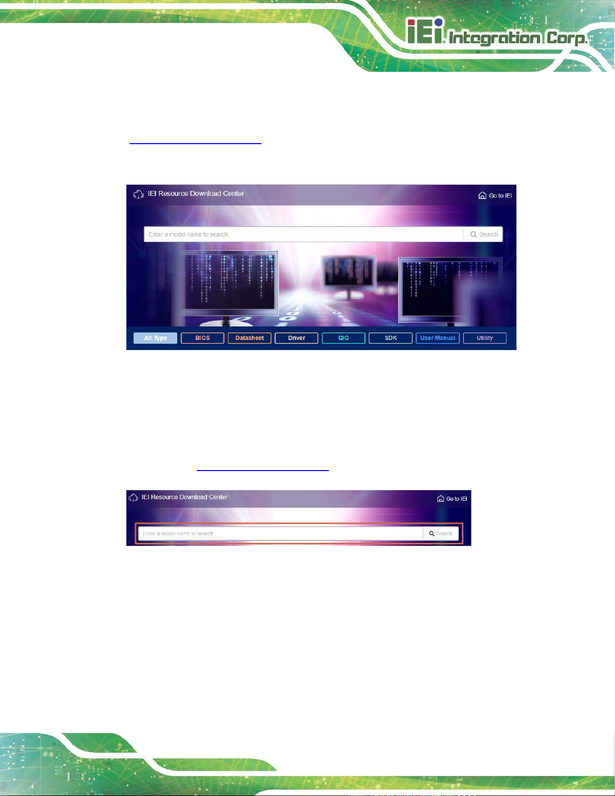
4.8 Software Installation
All the drivers for the PCIE-Q370 are available on IEI Resource Download Center
(https://download.ieiworld.com
software, utilities, and documentation.
Figure 4-12: IEI Resource Download Center
). Type PCIE-Q370 and press Enter to find all the relevant
4.8.1 Driver Download
To download drivers from IEI Resource Download Center, follow the steps below.
Step 1: Go to https://download.ieiworld.com
Step 2: All product-related software, util i ties, and documentation will be listed. You can
choose Driver to filter the result.
. Type PCIE-Q370 and press Enter.
Page 74

PCIE-Q370 Full-size PICMG 1.3 CPU Card
Page 60
its content. On Windows 7 system, an additional tool (such as Virtual
Step 3: Click the driver file name on the page an d you will be prompted with the
following window. You can download the entire ISO file (
arrow to find an individual driver and click the fil e name to download (
), or click the small
).
NOTE:
To install software from the downloaded ISO image file in Windows 8,
8.1 or 10, double-click the ISO file to mount it as a virtual drive to view
CD-ROM Control Panel from Microsoft) is needed to mount the file.
Page 75

PCIE-Q370 Full-size PICMG 1.3 CPU Card
Page 61
password rule (containing at least one upper case letter, one lower
4.9 Intel® AMT Setup Procedure
The PCIE-Q370 is featured with the Intel® Active Management Technology (AMT). To
enable the Intel® AMT function, follow the steps below.
Step 1: Make sure at least one of the memory sockets is installed with a DDR4 DIMM.
Step 2: Connect an Ethernet cable to the RJ-45 connector labeled LAN1.
Step 3: The AMI B IOS options regarding the Intel® ME or Intel® AMT must be enabled,
Step 4: Properly install the Intel® Management E ngi ne Components drivers from the
iAMT Driver & Utility directory in the driver CD.
Step 5: Configure the Intel® Management Engine BI OS extension (MEBx). To get into
the Intel® MEBx settings, press <Ctrl+P> after a single beep during boot-up
process. Enter the Intel® current ME pass word as it requires (the Intel® default
password is admin). Step 0:
NOTE:
To change the password, enter a new password following the strong
case letter, one digit and one special character, and be at least eight
characters).
Page 76

PCIE-Q370 Full-size PICMG 1.3 CPU Card
Page 62
Chapter
5
5 BIOS
Page 77

PCIE-Q370 Full-size PICMG 1.3 CPU Card
Page 63
Some of the BIOS options may vary throughout the life cycle of the
5.1 Introduction
The BIOS is programmed onto the BIOS chip. The BI OS setup pro gram allows changes to
certain system settings. This chapter outli nes t he options that can be changed.
NOTE:
product and are subject to change without prior notice .
5.1.1 Starting Setup
The UEFI BIOS is activated when the computer is turned on. The setup program can be
activated in one of two ways.
1. Press the DEL or F2 key as soon as the system is turned on or
2. Press the DEL or F2 key when the “Press DEL or F2 to enter SETUP”
message appears on the screen.
If the message disappears before the DEL or F2 key is pres sed, restart the computer and
try again.
5.1.2 Using Setup
Use the arrow keys to highlight items, press ENTER to select, use the PageUp and
PageDown keys to change entries, press F1 for help and press E
keys are shown in the following table.
Key Function
Up arrow Move to previous item
Down arrow Move to next item
Left arrow Move to the item on the left hand side
Right arrow Move to the item on the right hand side
+ Increase the numeric value or make changes
SC to quit. Navigation
- Decrease the numeric value or make changes
Page Up Move to the previous page
Page Dn Move to the next page
Page 78

PCIE-Q370 Full-size PICMG 1.3 CPU Card
Page 64
Key Function
Esc Main Menu – Quit and not save changes into CMOS
F1 General help, only for Status Page Setup Menu and Option Page
F2 Load previous values
F3 Load optimized defaults
F4 Save changes and Exit BIOS
Table 5-1: BIOS Navigation Keys
5.1.3 Getting Help
When F1 is pr essed, a small help window describing the appropriate keys to use and the
Status Page Setup Menu and Option Page Setup Menu -- Exit
current page and return to Main Menu
Setup Menu
possible selections for the highlighted item appears. To exit the Help Window, press E
5.1.4 Unable to Reboot after Configuration Changes
If the computer cannot boot after changes to the system configuration is made, CMOS
defaults. Use the clear CMOS button described in Chapter 4.
5.1.5 BIOS Menu Bar
The menu bar on top of the BIOS screen has the foll owing main items:
Main – Changes the basic system configuration.
Advanced – Changes the advanced system settings.
Chipset – Changes the chipset settings.
Security – Sets User and Supervisor Passwords.
Boot – Changes the system boot configuration.
Save & Exit – Selects exit options and loads default settings
Server Mgmt – Configures system event log and B M C network parameters
The following sections completely describe the configuration options found in the menu
items at the top of the BIOS screen and listed above.
SC.
5.2 Main
The Main BIOS menu (BIOS Menu 1) appears when the BIOS Setup program is entered.
The Main menu gives an overview of the basic syste m i nformation.
Page 79

PCIE-Q370 Full-size PICMG 1.3 CPU Card
Page 65
Aptio Setup Utility – Copyright (C) 2018 American Megatrends, Inc.
Main
Advanced
Chipset
Security
Boot
Save & Exit
Version 2.20.1271. Copyright (C) 2018 American Megatrends, Inc.
BIOS Information
BIOS Vendor American Megatrends
Core Version 5.13
Compliancy UEFI 2.6; PI 1.4
Project Version B497AT1e.BIN
Build Date and Time 08/31/2018 15:23:23
iWDD Vendor iEi
iWDD Version B497ER10.bin
Processor Information
Name CoffeeLake DT
Brand String Intel(R) Core(TM)
i5-8500T CPU @ 2.10GHz
Frequency 2100 MHz
ID 0x906EA
Stepping R0/S0/N0
Number of Processors 6Core(s) / 6Thread(s)
Microcode Revision 84
GT Info GT2 (0x3E92)
IGFX VBIOS Version 1010
Memory RC Version 0.7.1.58
Total Memory 4096 MB
Memory Frequency 2400 MHz
Set the Date. Use Tab to
switch between Date
elements.
----------------------
: Select Screen
↑ ↓: Select Item
Enter: Select
+/-: Change Opt.
F1: General Help
F2: Previous Values
F3: Optimized Defaults
F4: Save & Exit
ESC: Exit
PCH Information
Name CNL PCH-H
PCH SKU Q370
Stepping B0
ME FW Version 12.0.0.1068
ME Firmware SKU Corporate SKU
Access Level Administrator
System Date [Thu 01/01/2018]
System Time [01:10:27]
BIOS Menu 1: Main
The Main menu has two user configurable fields:
Sy stem Date [xx/xx/xx]
Use the System Date option to set the system date. Manually enter the day, month and
year.
Page 80
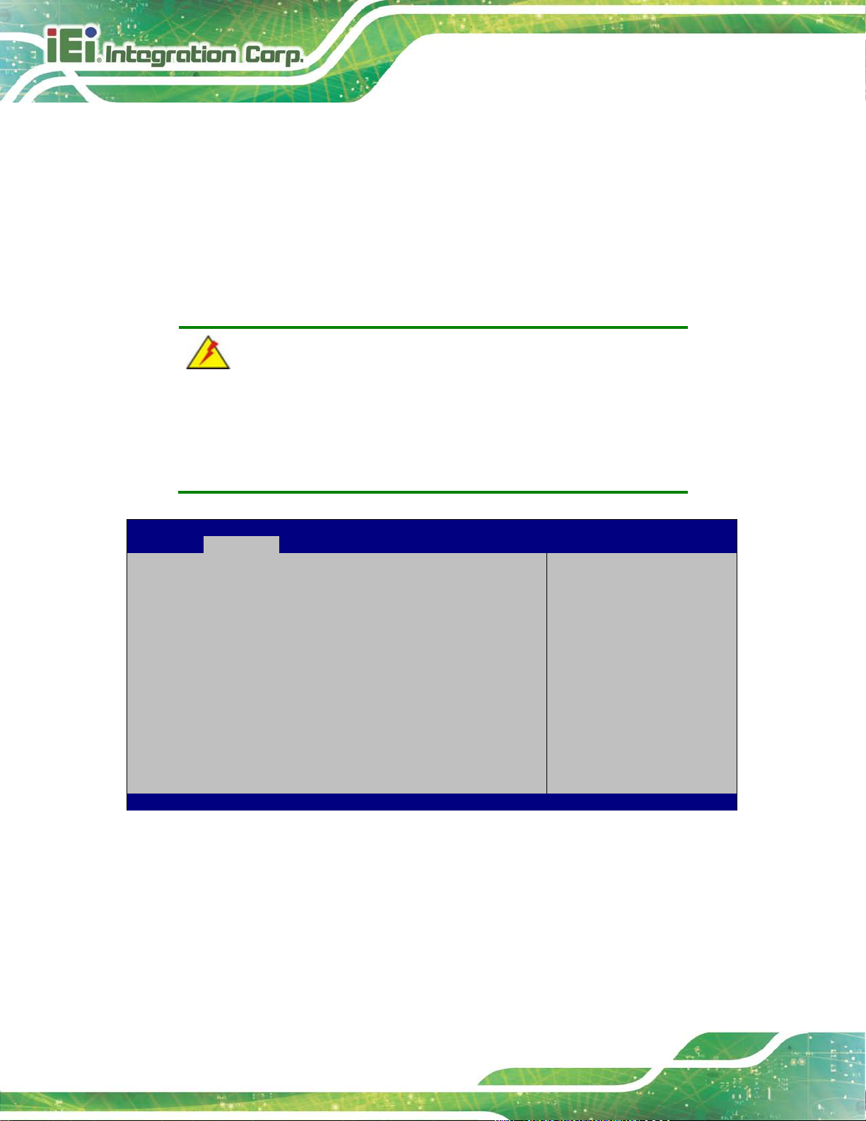
PCIE-Q370 Full-size PICMG 1.3 CPU Card
Page 66
Aptio Setup Utility – Copyright (C) 2018 American Megatrends, Inc.
Main
Advanced
Chipset
Security
Boot
Save & Exit
Version 2.20.1271. Copyright (C) 2018 American Megatrends, Inc.
BIOS Menu 2: Advanced
Sy stem Time [xx:xx:xx]
Use the System Time option to set the system time. Manually enter the hours, minutes
and seconds.
5.3 Advanced
Use the Advanced menu (BIOS Menu 2) to configure the CPU and peripheral devices
through the following sub-menus:
WARNING!
Setting the wrong values in the sections below may cause the system
to malfunction. Make sure that the settings made are compatible with
the hardware.
> CPU Configuration
> PCH-FW Configuration
> Trusted Computing
> ACPI Settings
> iWDD H/M Monitor
> F81866 Super IO Configuration
> RTC Wake Settings
> Serial Port Console Redirection
> USB Configuration
> CSM Configuration
> NVMe Configuration
> iEi Feature
Trusted Computing
Settings
----------------------
: Select Screen
↑ ↓: Select Item
Enter: Select
+/-: Change Opt.
F1: General Help
F2: Previous Values
F3: Optimized Defaults
F4: Save & Exit
ESC: Exit
Page 81

PCIE-Q370 Full-size PICMG 1.3 CPU Card
Page 67
Aptio Setup Utility – Copyright (C) 2018 American Megatrends, Inc.
Advanced
When enabled, a VMM can
Version 2.20.1271. Copyright (C) 2018 American Megatrends, Inc.
5.3.1 CPU Configuration
Use the CPU Configuration menu (BIOS Menu 3) to view detailed CPU specifications or
enable the Intel Virtualization Technolog y.
CPU Configuration
Type Intel(R) Core(TM)
i5-8500T CPU @ 2.10GHz
ID 0x906EA
Speed 2100 MHz
L1 Data Cache 32 kB x 6
L1 Instruction Cache 32 kB x 6
L2 Cache 256 kB x 6
L3 Cache 9 MB
L4 Cache N/A
VMX Supported
SMX/TXT Supported
Intel (VMX) Virtualization [Disabled]
Technology
Active Processor Cores [All]
Intel(R) SpeedStep(tm) [Enabled]
C states [Disabled]
Intel Trusted Execution Technology [Disabled]
utilize the additional
hardware capabilities
provided by Vanderpool
Technology.
----------------------
: Select Screen
↑ ↓: Select Item
Enter: Select
+/-: Change Opt.
F1: General Help
F2: Previous Values
F3: Optimized Defaults
F4: Save & Exit
ESC: Exit
Intel (VMX) Virtuali za tion Technology [Disabled]
Use the Intel (VMX) Virtualization Technology option to enable or disable virtualization
on the system. When combined with third party software, Intel® Virtualization technology
allows several OSs to run on the same system at the same time.
BIOS Menu 3: CPU Configuration
Disabled DEFAULT
Enabled
Disables Intel Virtualization Technology.
Enables Intel Virtualization Techn ol ogy.
Page 82

PCIE-Q370 Full-size PICMG 1.3 CPU Card
Page 68
Activ e Processor Cores [ All ]
Use the Active Processor Cores BIOS option to enable numbers of cores in the
processor package.
All DEFAULT
1
2
3
4
5
Intel(R) SpeedStep(tm) [Enabled]
Use the Intel(R) SpeedStep(tm) option to enable or disable the Intel® SpeedStep
Technology which allows more than two frequency ranges to be supported.
Disabled
Enabled DEFAULT
Enable all cores in the processor package.
Enable one core in the processor package.
Enable two cores in the processor package.
Enable three cores in the processor package.
Enable four cores in the processor package.
Enable five cores in the processor package.
Disables Intel® SpeedStep Technology
Enables Intel® SpeedStep Technology
C states [Disabled]
Use the C states option to enable or disable CPU power management which allows CPU
to go to C states when it is not 100% utilized.
Disabled DEFAULT
Enabled
Disables CPU power management
Enables CPU power management
Page 83
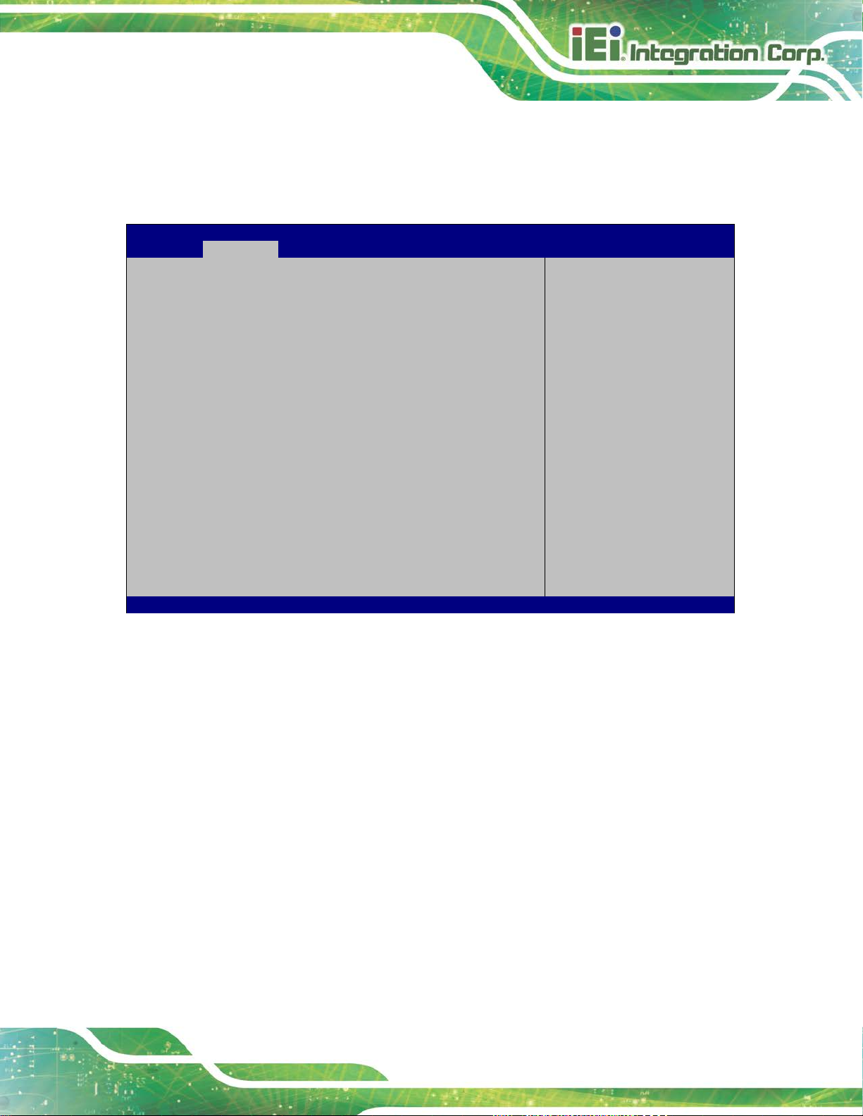
PCIE-Q370 Full-size PICMG 1.3 CPU Card
Page 69
Aptio Setup Utility – Copyright (C) 2018 American Megatrends, Inc.
Advanced
ESC Exit
Version 2.20.1271. Copyright (C) 2018 American Megatrends, Inc.
Not unconfigure ME with resetting MEBx password
5.3.2 PCH-FW Configuration
The PCH-FW Configuration menu (BIOS Menu 4) allows Intel® Active Management
Technology (AMT) options to be configured.
AMT BIOS Features [Enabled]
Unconfigure ME [Disabled]
BIOS Menu 4: PCH-FW Configuration
AMT BIOS Features [Enabled]
When disabled AMT BIOS
Features are no longer
supported and user is no
longer able to access
MEBx Setup.
Note:
This option does not
disable Manageability
Features in FW.
---------------------
: Select Screen
↑ ↓: Select Item
Enter Select
F1 General Help
F2 Previous Values
F3 Optimized
Defaults
F4 Save
Use the AMT BIOS Features option to enable or disable the access to MEBx setup.
Disabled
Enabled DEFAULT
Unconfigure M E [Disabled]
Use the Unconfigure ME option to unconfigure ME with resetting MEBx password to
default.
Disabled DEFAULT
Disable access to MEBx setup.
Enable access to MEBx setup.
to default
Page 84
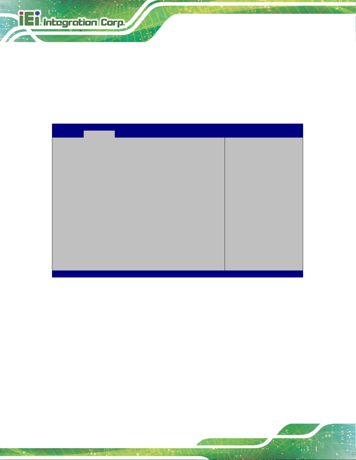
PCIE-Q370 Full-size PICMG 1.3 CPU Card
Page 70
Unconfigure ME with resetting MEBx password to
Aptio Setup Utility – Copyright (C) 2018 American Megatrends, Inc.
Advanced
Version 2.20.1271. Copyright (C) 2018 American Megatrends, Inc.
Enabled
5.3.3 Trusted Computing
Use the Trusted Computing menu (BIOS Menu 5) to configure settings related to the
Trusted Computing Group (TCG) Trusted P l atform Module (TPM).
default
Configuration
Security Device Support [Disable]
NO Security Device Found
BIOS Menu 5: Trusted Computing
Security Device Support [Disable]
Enables or Disables BIOS
support for security
device. O.S. will not
show Security Device.
TCG EFI protocol and
INT1A interface will not
be available.
----------------------
: Select Screen
↑ ↓: Select Item
Enter: Select
+/-: Change Opt.
F1: General Help
F2: Previous Values
F3: Optimized Defaults
F4: Save & Exit
ESC: Exit
Use the Security Device Support option to configu re support for the TPM.
Disable DEFAULT
Enable
TPM support is disabled.
TPM support is enabled.
Page 85
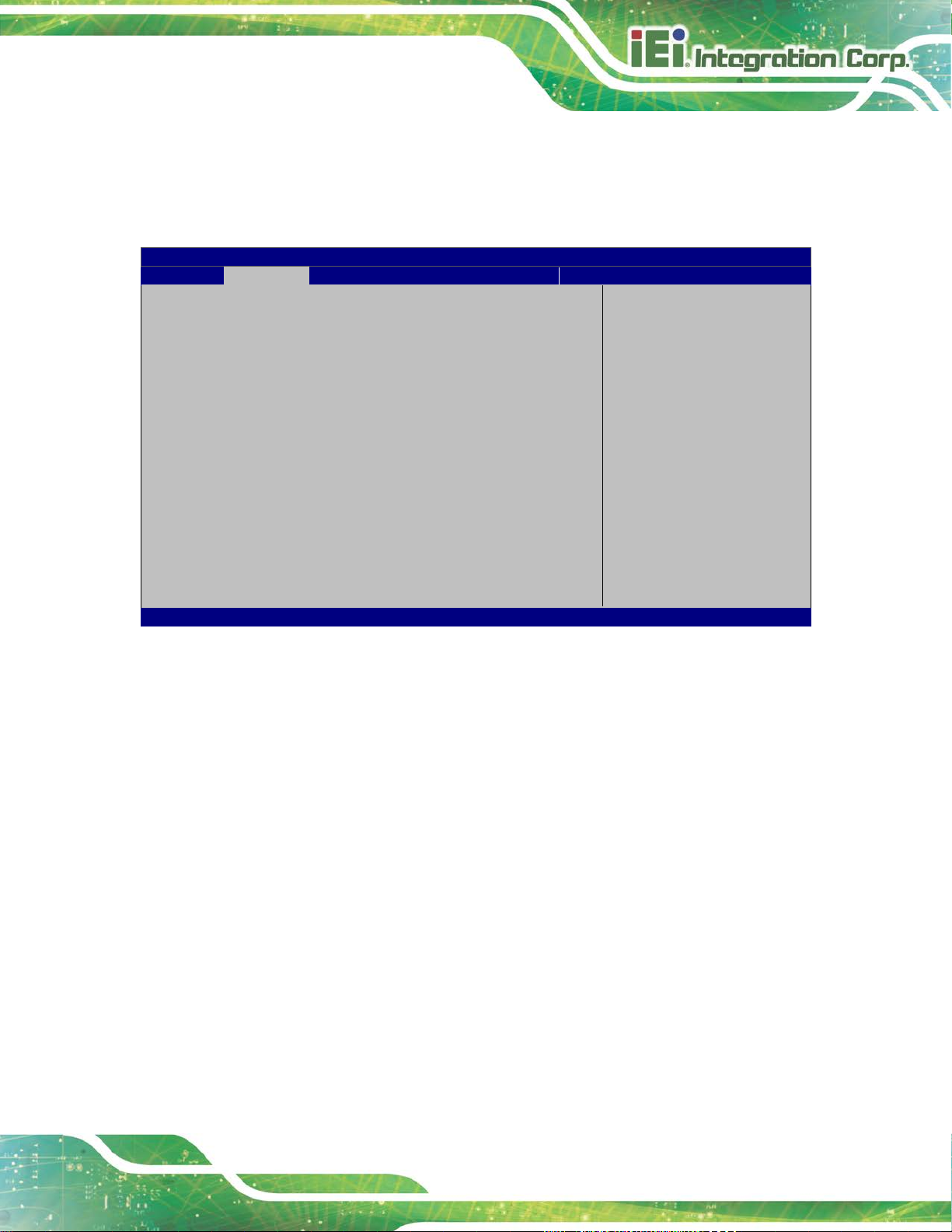
PCIE-Q370 Full-size PICMG 1.3 CPU Card
Page 71
Aptio Setup Utility – Copyright (C) 2018 American Megatrends, Inc.
Advanced
Select ACPI sleep state
when the SUSPEND button
ESC: Exit
Version 2.20.1271. Copyright (C) 2018 American Megatrends, Inc.
The caches are flushed and the CPU is
a working
5.3.4 ACPI Settings
The ACPI Settings menu (BIOS Menu 6) configures the Advanced Configuration and
Power Interface (ACPI) options.
ACPI Settings
ACPI Sleep State [S3(Suspend to RAM)]
the system will enter
is pressed.
----------------------
: Select Screen
↑ ↓: Select Item
Enter: Select
+/-: Change Opt.
F1: General Help
F2: Previous Values
F3: Optimized Defaults
F4: Save & Exit
ACPI Sleep State [S3 (Suspend to RAM)]
Use the ACPI Sleep State option to specify the sleep state the system enters when it is
not being used.
BIOS Menu 6: ACPI Settings
S3 (Suspend to
RAM)
DEFAULT
powered off. Power to the RAM is maintained.
The computer returns slower to
state, but more power is saved.
Page 86
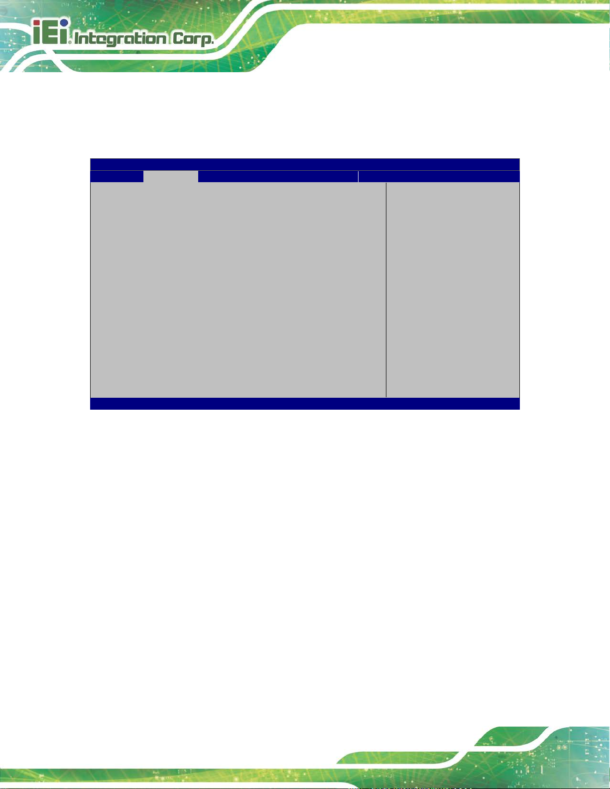
PCIE-Q370 Full-size PICMG 1.3 CPU Card
Page 72
Aptio Setup Utility – Copyright (C) 2018 American Megatrends, Inc.
Advanced
Version 2.20.1271. Copyright (C) 2018 American Megatrends, Inc.
5.3.5 iWDD H/W Monitor
The iWDD H/W Monitor menu (BIOS Menu 7) contains the fan configuration submenu,
and displays the system temperature and CPU fan speed.
PC Health Status
CPU temperature :+42 °C
System temperature :+34 °C
CPU_FAN1 Speed :2151 RPM
SYS_FAN1 Speed :N/A
CPU_CORE :+0.806 V
+5V :+5.023 V
+12V :+12.064 V
+DDR :+1.196 V
+5VSB :+5.070 V
+3.3V :+3.310 V
+3.3VSB :+3.288 V
> Smart Fan Mode Configuration
BIOS Menu 7: iWDD H/W Monitor
PC Health Status
The following system parameters and values are shown. The system parameters that are
Smart Fan Mode Select
---------------------
: Select Screen
↑ ↓: Select Item
Enter: Select
+/-: Change Opt.
F1: General Help
F2: Previous Values
F3: Optimized Defaults
F4: Save & Exit
ESC: Exit
monitored are:
System Temperatures:
o CPU Temperature
o System Temperature
Fan Speeds:
o CPU Fan Speed
o System Fan Speed
Voltages:
o CPU_CORE
o +5V
Page 87
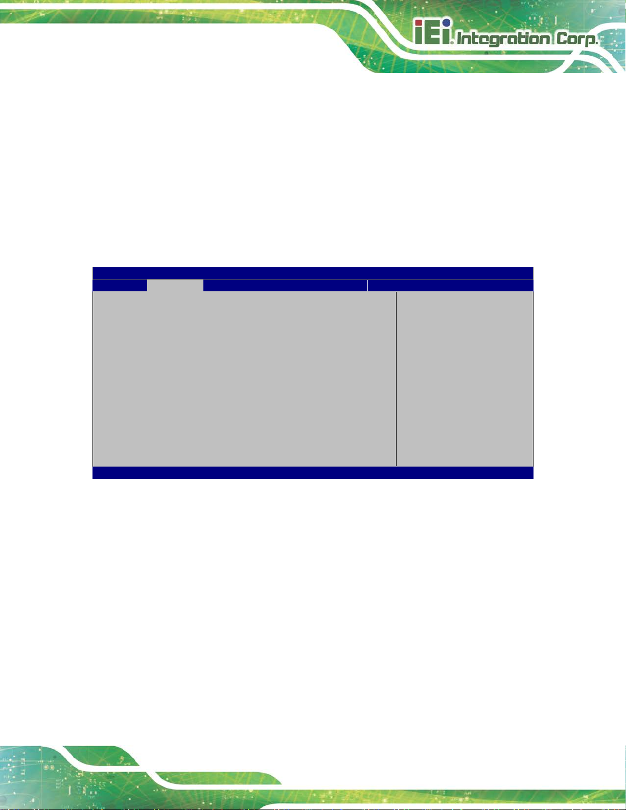
PCIE-Q370 Full-size PICMG 1.3 CPU Card
Page 73
Aptio Setup Utility – Copyright (C) 2018 American Megatrends, Inc.
Advanced
Version 2.20.1271. Copyright (C) 2018 American Megatrends, Inc.
The fan spins at the speed set in Manual Mode
The fan adjusts its speed using Auto Mode
o +12V
o DDR
o +5VSB
o +3.3V
o +3.3VSB
5.3.5.1 Smart Fan Mode Configuration
Use the Smart Fan Mode Configuration submenu (BIOS Menu 8) to configure the
CPU/system fan temperature and speed settings.
Smart Fan Mode Configuration
CPU_FAN1 Smart Fan Control [Auto Mode]
Auto mode fan start temperature 50
Auto mode fan off temperature 40
Auto mode fan start PWM 30
Auto mode fan slope PWM 2
SYS_FAN1 Smart Fan Control [Auto Mode]
Auto mode fan start temperature 50
Auto mode fan off temperature 40
Auto mode fan start PWM 30
Auto mode fan slope PWM 1
BIOS Menu 8: Smart Fan Mode Configuration
CPU_FAN1 Smart Fan Control/SYS_FAN1 Smart Fan Control [Auto Mode]
Use the CPU_FAN1 Smart Fan Control/SYS_FAN1 Smart Fan Control option to
configure the CPU/System Smart Fan.
Manual Mode
Smart Fan Mode Select
---------------------
: Select Screen
↑ ↓: Select Item
Enter: Select
+/-: Change Opt.
F1: General Help
F2: Previous Values
F3: Optimized Defaults
F4: Save & Exit
ESC: Exit
Auto Mode DEFAULT
The following options can only be set if the CPU/SYS Smart Fan Control option is set to
Auto Mode.
settings.
settings.
Page 88

PCIE-Q370 Full-size PICMG 1.3 CPU Card
Page 74
Auto mode fan start temperature
If the CPU temperature is between fan off and fan s tart, the fan speed change to fan
start PWM. To set a value, Use the + or – key to change the value or enter a decimal
number between 1 and 100.
Auto mode fan off temperature
If the CPU temperature is lower than the value set this option, the fan spe ed change to be
lowest. To set a value, Use the + or – key to change the value or enter a decimal number
between 1 and 100.
Auto mode fan start PWM
Use the Auto mode fan start PWM option to set the PWM start value. Use the + or – key
to change the value or enter a decimal number bet ween 1 and 100.
Auto mode fan slope PWM
Use the Auto mode fan slope PWM option to select the linear rate at which the PWM
mode increases with respect to an increase in temperature. Use the + or – key to change
the value or enter a decimal number between 1 and 8.
Page 89

PCIE-Q370 Full-size PICMG 1.3 CPU Card
Page 75
Aptio Setup Utility – Copyright (C) 2018 American Megatrends, Inc.
Advanced
Version 2.20.1271. Copyright (C) 2018 American Megatrends, Inc.
5.3.6 F81866 Super IO Configuration
Use the F81866 Super IO Configuration menu (BIOS Menu 9) to set or change the
configurations for the parallel ports and serial ports.
Super IO Configuration
Super IO Chip F81866
> Serial Port 1 Configuration
> Serial Port 2 Configuration
> Serial Port 3 Configuration
> Serial Port 4 Configuration
Case Open Detection [Disabled]
BIOS Menu 9: F81866 Super IO Configuration
Case Open Beep [Disabled]
Use the Case Open Beep option to enable or disabl e the case open beep function.
Disabled DEFAULT
Disable the case open beep function
Set Parameters of Serial
Port 1 (COMA)
---------------------
: Select Screen
↑ ↓: Select Item
Enter: Select
+/-: Change Opt.
F1: General Help
F2: Previous Values
F3: Optimized Defaults
F4: Save & Exit
ESC: Exit
Enabled
Enable the case open beep function
Page 90

PCIE-Q370 Full-size PICMG 1.3 CPU Card
Page 76
Aptio Setup Utility – Copyright (C) 2018 American Megatrends, Inc.
Advanced
ESC: Exit
Version 2.20.1271. Copyright (C) 2018 American Megatrends, Inc.
5.3.6.1 Serial Port 1 Configuration
Use the Serial Port 1 Configuration menu (BIOS Menu 10) to configure the serial port n.
Serial Port n Configuration
Serial Port [Enabled]
Device Settings IO=3F8h; IRQ=4
BIOS Menu 10: Serial Port 1 Configuration Menu
Serial P ort [ Enabled]
Use the Serial Port option to enable or disable the serial port.
Disabled
Disable the serial port
Enable or Disable Serial
Port (COM)
---------------------
: Select Screen
↑ ↓: Select Item
Enter: Select
+/-: Change Opt.
F1: General Help
F2: Previous Values
F3: Optimized Defaults
F4: Save & Exit
Enabled DEFAULT
Enable the serial port
Page 91

PCIE-Q370 Full-size PICMG 1.3 CPU Card
Page 77
Aptio Setup Utility – Copyright (C) 2018 American Megatrends, Inc.
Advanced
ESC: Exit
Version 2.20.1271. Copyright (C) 2018 American Megatrends, Inc.
5.3.6.2 Serial Port 2 Configuration
Use the Serial Port 2 Configuration menu (BIOS Menu 11: Serial Port 2 Configuration
MenuBIOS Menu 11) to configure the serial port n.
Serial Port n Configuration
Serial Port [Enabled]
Device Settings IO=2F8h; IRQ=3
BIOS Menu 11: Serial Port 2 Configuration Menu
Serial P ort [ Enabled]
Use the Serial Port option to enable or disable the serial port.
Disabled
Disable the serial port
Enable or Disable Serial
Port (COM)
---------------------
: Select Screen
↑ ↓: Select Item
Enter: Select
+/-: Change Opt.
F1: General Help
F2: Previous Values
F3: Optimized Defaults
F4: Save & Exit
Enabled DEFAULT
Enable the serial port
Page 92

PCIE-Q370 Full-size PICMG 1.3 CPU Card
Page 78
Aptio Setup Utility – Copyright (C) 2018 American Megatrends, Inc.
Advanced
ESC: Exit
Version 2.20.1271. Copyright (C) 2018 American Megatrends, Inc.
5.3.6.3 Serial Port 3 Configuration
Use the Serial Port 3 Configuration menu (BIOS Menu 12) to configure the serial port n.
Serial Port n Configuration
Serial Port [Enabled]
Device Settings IO=3E8h; IRQ=7
BIOS Menu 12: Serial Port 3 Configuration Menu
Serial P ort [ Enabled]
Use the Serial Port option to enable or disable the serial port.
Disabled
Disable the serial port
Enable or Disable Serial
Port (COM)
---------------------
: Select Screen
↑ ↓: Select Item
Enter: Select
+/-: Change Opt.
F1: General Help
F2: Previous Values
F3: Optimized Defaults
F4: Save & Exit
Enabled DEFAULT
Enable the serial port
Page 93

PCIE-Q370 Full-size PICMG 1.3 CPU Card
Page 79
Aptio Setup Utility – Copyright (C) 2018 American Megatrends, Inc.
Advanced
ESC: Exit
Version 2.20.1271. Copyright (C) 2018 American Megatrends, Inc.
5.3.6.4 Serial Port 4 Configuration
Use the Serial Port 4 Configuration menu (BIOS Menu 13) to configure the serial port n.
Serial Port n Configuration
Serial Port [Enabled]
Device Settings IO=2E8h; IRQ=7
BIOS Menu 13: Serial Port 4 Configuration Menu
Serial P ort [ Enabled]
Use the Serial Port option to enable or disable the serial port.
Disabled
Disable the serial port
Enable or Disable Serial
Port (COM)
---------------------
: Select Screen
↑ ↓: Select Item
Enter: Select
+/-: Change Opt.
F1: General Help
F2: Previous Values
F3: Optimized Defaults
F4: Save & Exit
Enabled DEFAULT
Transfer Mode [RS485]
Use the Transfer Mode option to select the Serial Port 4 signaling mode.
RS485 DEFAULT
Enable the serial port
Serial Port 4 signaling mode is RS-485
Page 94

PCIE-Q370 Full-size PICMG 1.3 CPU Card
Page 80
Aptio Setup Utility – Copyright (C) 2018 American Megatrends, Inc.
Advanced
Version 2.20.1271. Copyright (C) 2018 American Megatrends, Inc.
The real time clock (RTC) cannot generate a wake
every day at the specified time. Besides, the
following options appear with values that can be
5.3.7 RTC Wake Settings
The RTC Wake Settings menu (BIOS Menu 14) enables the system to wake at the
specified time.
Wake system with Fixed Time [Disabled]
BIOS Menu 14: RTC Wake Settings
Wake system with Fixed Time [Disabled]
Use the Wake system with Fixed Time option to enable or disable the system wake on
Enable or disable System
wake on alarm event. When
enabled, System will
wake on the
date::hr::min::sec
specified
----------------------
: Select Screen
↑ ↓: Select Item
Enter: Select
+/-: Change Opt.
F1: General Help
F2: Previous Values
F3: Optimized Defaults
F4: Save & Exit
ESC: Exit
alarm event.
Disabled D
Enabled
EFAULT
event
If selected, the Wake up every day option appears
allowing you to enable to disable the sy st em t o wake
selected:
Wake up date
Wake up hour
Page 95

PCIE-Q370 Full-size PICMG 1.3 CPU Card
Page 81
Aptio Setup Utility – Copyright (C) 2018 American Megatrends, Inc.
Advanced
ESC: Exit
Version 2.20.1271. Copyright (C) 2018 American Megatrends, Inc.
5.3.8 Serial Port Console Redirection
The Serial Port Console Redirection menu (BIOS Menu 15) allows the console
redirection options to be configured. Console redirection allows users to maintain a
system remotely by re-directing keyboard input and text output through the serial port.
Wake up minute
Wake up second
After setting the alarm, the computer turns itself on
from a suspend state when the alarm goes off.
COM1
Console Redirection [Disabled]
> Console Redirection Settings
COM2
Console Redirection [Disabled]
> Console Redirection Settings
COM3
Console Redirection [Disabled]
> Console Redirection Settings
COM4
Console Redirection [Disabled]
> Console Redirection Settings
iAMT SOL
COM5 (Pci Bus0,Dev0,Func0) (Disabled)
Console Redirection Port Is Disabled
Legacy Console Redirection
> Legacy Console Redirection Settings
Console Redirection
Enable or Disable
---------------------
: Select Screen
↑ ↓: Select Item
Enter: Select
+/-: Change Opt.
F1: General Help
F2: Previous Values
F3: Optimized Defaults
F4: Save & Exit
BIOS Menu 15: Serial Port Console Redirection
Page 96

PCIE-Q370 Full-size PICMG 1.3 CPU Card
Page 82
Console Redirection [Disabled]
Use Console Redirection option to enable or disable the con sole redirection function.
Disabled DEFAULT
Enabled
The following options are available in the Console Redirection Settings submenu when
the Console Redirection option is enabled.
Terminal Type [ANSI]
Use the Terminal Type option to specify the remote termi nal type.
VT100
VT100+
VT-UTF8
ANSI DEFAULT
Bits per second [115200]
Disabled the console redirection function
Enabled the console redirection function
The target terminal type is VT100
The target terminal type is VT100+
The target terminal type is VT-UTF8
The target terminal type is ANSI
Use the Bits per second option to specify the serial port transmission speed. The speed
must match the other side. Long or noisy lines may require lower speeds.
Data Bits [8]
Use the Data Bits option to specify the number of data bits.
9600
19200
57600
115200 DEFAULT
7
8 DEFAULT
Sets the serial port transmission speed at 9600.
Sets the serial port transmission speed at 19200.
Sets the serial port transmission speed at 57600.
Sets the serial port transmission speed at 115200.
Sets the data bits at 7.
Sets the data bits at 8.
Page 97

PCIE-Q370 Full-size PICMG 1.3 CPU Card
Page 83
The parity bit is always 1. This option does not
is always 0. This option does not
Parity [None]
Use the Parity option to specify the parity bit that can be sent with the data bits for
detecting the transmission errors.
None DEFAULT
Even
Odd
Mark
Space
Stop Bits [1]
Use the Stop Bits option to specify the number of stop bits used to indicate the end of a
serial data packet. Communication with slow devices may require more than 1 stop bit.
1 DEFAULT
No parity bit is sent with the data bits.
The parity bit is 0 if the number of ones in the data
bits is even.
The parity bit is 0 if the number of ones in the data
bits is odd.
provide error detection.
The parity bit
provide error detection.
Sets the number of stop bits at 1.
2
Sets the number of stop bits at 2.
Page 98
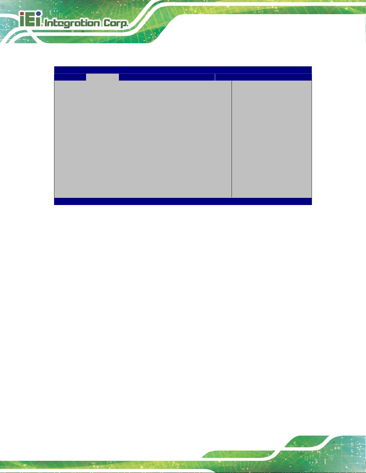
PCIE-Q370 Full-size PICMG 1.3 CPU Card
Page 84
Aptio Setup Utility – Copyright (C) 2018 American Megatrends, Inc.
Advanced
Version 2.20.1271. Copyright (C) 2018 American Megatrends, Inc.
5.3.8.1 Legacy Console Redirection Settings
Legacy Serial Redirection Port [COM1]
BIOS Menu 16: Legacy Console Redirection Settings
Legacy Serial Redirec tion Port [COM1]
Use the Legacy Serial Redirection Port option to select a COM port to display
redirection of legacy OS and legacy OPROM messages. Configuration options are listed
Select a COM port to
display redirection of
Legacy OS and Legacy
OPROM Messages.
---------------------
: Select Screen
↑ ↓: Select Item
Enter: Select
+/-: Change Opt.
F1: General Help
F2: Previous Values
F3: Optimized Defaults
F4: Save & Exit
ESC: Exit
below.
COM1 Default
COM2
COM3
COM4
COM5 (Pci Bus0,Dev0,Func0) (Disabled)
Page 99
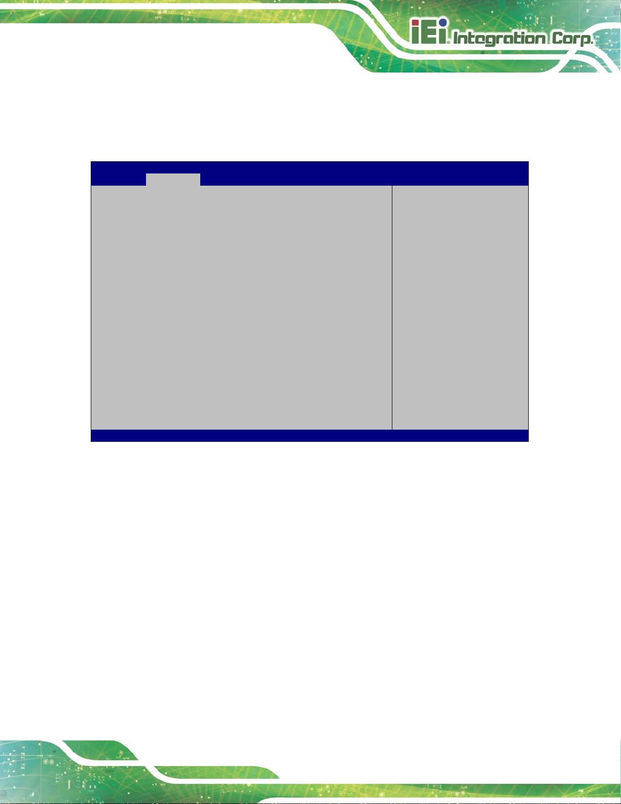
PCIE-Q370 Full-size PICMG 1.3 CPU Card
Page 85
Aptio Setup Utility – Copyright (C) 2018 American Megatrends, Inc.
Advanced
disables legacy support
Version 2.20.1271. Copyright (C) 2018 American Megatrends, Inc.
5.3.9 USB Configuration
Use the USB Configuration menu (BIOS Menu 17) to read USB configuration
information and configure the USB settin gs.
USB Configuration
USB Controllers:
1 XHCI
USB Devices:
1 Keyboard
Legacy USB Support [Enabled]
BIOS Menu 17: USB Configuration
Legacy USB Support [Enabled]
Enables Legacy USB
support. AUTO option
if no USB devices are
connected. DISABLE
option will keep USB
devices available only
for EFI applications.
---------------------
: Select Screen
↑ ↓: Select Item
Enter: Select
+/-: Change Opt.
F1: General Help
F2: Previous Values
F3: Optimized Defaults
F4: Save & Exit
ESC: Exit
Use the Legacy USB Support BIOS option to enable USB mouse and USB keyboard
support. Normally if this option is not enable d, any a t tached USB m ouse o r US B key board
does not become available until a USB comp atible operat ing syst em is fully bo oted with all
USB drivers loaded. When this option is enabled, any attached USB mouse or USB
keyboard can control the system even when there is no USB driver loaded onto the
system.
Enabled DEFAULT
Disabled
Auto
Legacy USB support enabled
Legacy USB support disabled
Legacy USB support disabled if no USB devices are
connected
Page 100

PCIE-Q370 Full-size PICMG 1.3 CPU Card
Page 86
Aptio Setup Utility – Copyright (C) 2018 American Megatrends, Inc.
Advanced
ESC: Exit
Version 2.20.1271. Copyright (C) 2018 American Megatrends, Inc.
5.3.10 CSM Configuration
The CSM Configuration menu (BIOS Menu 18) configures the CSM (Compatibility
Support Module) support.
Compatibility Support Module Configuration
CSM Support [Enabled]
BIOS Menu 18: CSM Configuration
CSM Support [Enabled]
Use the CSM Support option to enable or disable CSM support.
Disabled
Disable CSM support.
Enable/Disable CSM
Support.
----------------------
: Select Screen
↑ ↓: Select Item
Enter: Select
+/-: Change Opt.
F1: General Help
F2: Previous Values
F3: Optimized Defaults
F4: Save & Exit
Enabled DEFAULT
Enable CSM support.
 Loading...