

Page 1
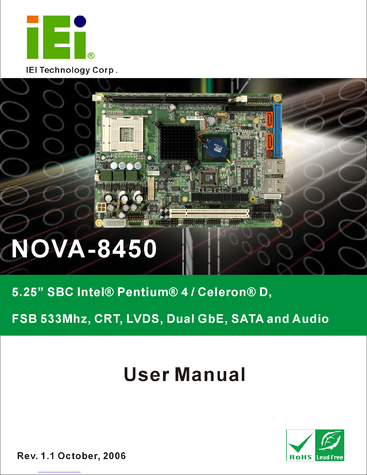
NOVA-8450 CPU Card
NOVA-8450 CPU Card
1
1
Page 2
REVISION HISTORY
Title NOVA-8450 Intel® Pentium® 4/
Intel® Celeron® D Socket 478 CPU Card
Revision Number Description Date of Issue
1.0 Initial release July 2006
1.1 - Revised front panel connector pin 1 description.
- Revised inverter connector pin 1 description.
- Revised COM2 pin numbering.
- Revised Watchdog Timer.
October 2006
COPYRIGHT NOTICE
The information in this document is subject to change without prior notice in order to
improve reliability, design and function and does not represent a commitment on the part of
the manufacturer.
In no event will the manufacturer be liable for direct, indirect, special, incidental, or
consequential damages arising out of the use or inability to use the product or
documentation, even if advised of the possibility of such damages.
This document contains proprietary information protected by copyright. All rights are
reserved. No part of this manual may be reproduced by any mechanical, electronic, or
2
other means in any form without prior written permission of the manufacturer.
TRADEMARKS
IBM PC is a registered trademark of International Business Machines Corporation. INTEL
is a registered trademark of INTEL Corporation. AMI is registered trademarks of American
Megatrends Inc. Other product names mentioned herein are used for identification
purposes only and may be trademarks and/or registered trademarks of their respective
owners.
IEI® Technology, Corp.
Page 3

NOVA-8450 CPU Card
Table of Contents
1 Introduction............................................................................................................. 15
1.1 NOVA-8450 CPU CARD OVERVIEW ................................................................. 16
1.1.1 NOVA-8450 CPU Card Applications............................................................... 16
1.1.2 NOVA-8450 CPU Card Benefits...................................................................... 16
1.1.3 NOVA-8450 CPU Card Features ..................................................................... 16
1.2 NOVA-8450 CPU CARD OVERVIEW ................................................................. 17
1.2.1 NOVA-8450 CPU Card Connectors................................................................. 18
1.2.2 Technical Specifications: ................................................................................. 18
2 Detailed Specifications............................................................................................ 21
2.1 CPU SUPPORT.................................................................................................... 22
2.1.1 Intel® Pentium® 4........................................................................................... 22
2.1.2 Intel® Celeron® D........................................................................................... 22
2.2 ONBOARD CHIPSETS .......................................................................................... 23
2.2.1 Northbridge and Southbridge Chipsets ........................................................... 23
2.2.2 845GV Northbridge Chipset ............................................................................ 23
2.2.3 ICH4 Southbridge Chipset............................................................................... 24
2.3 DATA FLOW........................................................................................................ 25
2.4 GRAPHICS SUPPORT ........................................................................................... 26
2.5 MEMORY SUPPORT............................................................................................. 28
2.6 PCI B
2.7 SUPER I/O .......................................................................................................... 28
2.8 BIOS ................................................................................................................. 31
2.9 PXE: PRE-BOOT EXECUTION ENVIRONMENT .................................................... 31
2.10 GBE ETHERNET ................................................................................................. 32
2.11 DRIVE INTERFACES ............................................................................................ 32
2.11.1 SATA Drives.................................................................................................... 33
US INTERFACE SUPPORT ........................................................................... 28
2.11.2 IDE HDD Interfaces....................................................................................... 33
2.12 SERIAL PORTS .................................................................................................... 33
2.13 PCI I
2.14 USB INTERFACES............................................................................................... 33
2.15 INFRARED DATA ASSOCIATION (IRDA) INTERFACE ............................................ 33
NTERFACES ................................................................................................ 33
3
Page 4

2.16 AUDIO CODEC.................................................................................................... 34
2.17 POWER CONSUMPTION....................................................................................... 35
2.18 SYSTEM MONITORING........................................................................................ 35
2.19 REAL TIME CLOCK............................................................................................. 36
2.20 OPERATING TEMPERATURE AND TEMPERATURE CONTROL................................. 36
2.21 PACKAGED CONTENTS AND OPTIONAL ACCESSORY ITEMS................................. 36
2.21.1 Package Contents........................................................................................... 36
2.21.2 Optional Accessory Items............................................................................... 37
3 Connectors and Jumpers........................................................................................ 39
3.1 PERIPHERAL INTERFACE CONNECTORS .............................................................. 40
3.1.1 NOVA-8450 CPU Card Layout........................................................................ 40
3.1.2 Peripheral Interface Connectors ..................................................................... 41
3.1.3 Rear Panel Connectors .................................................................................... 42
3.1.4 Onboard Jumpers............................................................................................. 43
3.2 INTERNAL PERIPHERAL CONNECTORS ................................................................ 43
3.2.1 Bit GPIO Connector ........................................................................................ 43
3.2.2 ATX-12V Power Source Connector.................................................................. 45
3.2.3 ATX Power On Switch Connector.................................................................... 46
3.2.4 Audio Connector .............................................................................................. 47
3.2.5 ATX Connector................................................................................................. 48
3.2.6 Battery Connector............................................................................................ 49
3.2.7 Compact Flash Connector ............................................................................... 51
3.2.8 CPU Cooling Fan Connector .......................................................................... 52
3.2.9 External Power Connector .............................................................................. 53
3.2.10 Front Panel Connector .................................................................................. 55
3.2.11 IDE Interface Connector (Primary)............................................................... 56
3.2.12 IDE Interface Connector (Secondary) ........................................................... 58
3.2.13 Inverter Connector......................................................................................... 60
3.2.14 IrDA Connector.............................................................................................. 61
3.2.15 Keyboard/Mouse Connector .......................................................................... 62
3.2.16 LVDS LCD Panel Connector ......................................................................... 63
3.2.17 Parallel Port Connector ................................................................................ 64
3.2.18 PCI-104 Connector........................................................................................ 66
3.2.19 PCI2 Connector ............................................................................................. 68
3.2.20 SATA Drive Ports ........................................................................................... 70
4
IEI® Technology, Corp.
Page 5

NOVA-8450 CPU Card
3.2.21 RS-232 Serial Communications Connector ................................................... 71
3.2.22 RS-232/422/485 Serial Communications Connector ..................................... 73
3.2.23 Internal USB Connectors............................................................................... 74
3.2.24 VGA Connector .............................................................................................. 75
3.3 EXTERNAL (REAR PANEL) CONNECTORS ........................................................... 77
3.3.1 Ethernet Connector.......................................................................................... 77
3.4 ONBOARD JUMPERS ........................................................................................... 78
3.4.1 Clear CMOS Setup Jumper.............................................................................. 79
3.4.2 COM2 RS-232/422/485 Setup Jumper............................................................. 80
3.4.3 COM2 RS-422/485 Setup Jumper.................................................................... 81
3.4.4 COM2 Voltage Selection Jumper ..................................................................... 81
3.4.5 Compact Flash Card Setup Jumper................................................................. 82
3.4.6 LCD Panel (LVDS) Voltage select Jumper ...................................................... 82
3.4.7 PC104 Plus VIO Voltage Setup Jumper........................................................... 83
4 Installation and Configuration .............................................................................. 85
4.1 INSTALLATION CONSIDERATIONS ....................................................................... 86
4.1.1 Installation Notices .......................................................................................... 86
4.2 UNPACKING........................................................................................................ 87
4.2.1 Unpacking Precautions.................................................................................... 87
4.2.2 Checklist........................................................................................................... 87
4.3 NOVA-8450 CPU CARD INSTALLATION............................................................ 88
4.3.1 CPU Installation .............................................................................................. 89
4.3.2 Optional Cooling Kit (CF-521-RS) Installation .............................................. 90
4.3.3 DIMM Module Installation .............................................................................. 92
4.3.3.1 Purchasing the Memory Module............................................................... 92
4.3.3.2 DIMM Module Installation....................................................................... 92
4.3.4 Peripheral Device Connection......................................................................... 94
4.3.4.1 Compact Flash Disk.................................................................................. 94
4.3.4.2 IDE Disk Drive Connector (IDE1, IDE2)................................................. 94
4.3.4.3 Parallel Port Connector (LPT1) ................................................................ 95
4.3.4.4 Audio Interface.......................................................................................... 95
4.3.4.5 COM Port Connectors [COM1, COM2, COM3 and COM4]................... 95
4.3.4.6 VGA Connector......................................................................................... 96
4.3.4.7 LVDS Connector....................................................................................... 96
4.4 J
UMPER CONFIGURATION ................................................................................... 96
5
Page 6

4.5 CHASSIS INSTALLATION ..................................................................................... 97
4.6 REAR PANEL CONNECTORS ................................................................................ 97
5 AMI BIOS Setup ..................................................................................................... 99
5.1 INTRODUCTION ................................................................................................ 100
5.1.1 Starting Setup................................................................................................. 100
5.1.2 Using Setup .................................................................................................... 100
5.1.3 Getting Help................................................................................................... 101
5.1.4 Unable to Reboot After Configuration Changes............................................ 101
5.1.5 BIOS Main Menu ........................................................................................... 102
5.2 STANDARD CMOS SETUP ................................................................................ 105
5.3 A
DVANCED CMOS SETUP ................................................................................111
5.4 ADVANCED CHIPSET SETUP.............................................................................. 120
5.5 P
OWER MANAGEMENT SETUP.......................................................................... 126
5.6 PCI / PLUG AND PLAY SETUP ........................................................................... 135
5.7 PERIPHERAL SETUP .......................................................................................... 138
5.8 HARDWARE MONITOR SETUP ........................................................................... 144
5.9 AUTO-DETECT HARD DISKS ............................................................................ 146
6 Software Drivers ................................................................................................... 147
6.1 AVAILABLE SOFTWARE DRIVERS ...................................................................... 148
6.2 CHIPSET DRIVER INSTALLATION....................................................................... 148
6.3 INTEL® APPLICATION ACCELERATOR INSTALLATION ....................................... 152
6.4 INTEL® GRAPHICS MEDIA ACCELERATOR DRIVER .......................................... 153
6.5 REALTEK LAN DRIVER (FOR GBE LAN) INSTALLATION................................. 156
6.6 R
EALTEK AUDIO DRIVER INSTALLATION ......................................................... 159
6.7 ALI SATA/RAID DRIVER ............................................................................... 163
A BIOS Configuration Options ............................................................................... 167
A.1 BIOS CONFIGURATION OPTIONS ..................................................................... 168
B Watchdog Timer.................................................................................................... 173
C Address Mapping .................................................................................................. 177
C.1 I/O ADDRESS MAP ........................................................................................... 178
C.2 1
ST
MB MEMORY ADDRESS MAP ..................................................................... 178
C.3 IRQ MAPPING TABLE....................................................................................... 179
C.4 DMA CHANNEL ASSIGNMENTS ....................................................................... 179
6
IEI® Technology, Corp.
Page 7

NOVA-8450 CPU Card
D External AC’97 Audio CODEC ........................................................................... 181
D.1 I
NTRODUCTION ................................................................................................ 182
D.1.1 Accessing the AC’97 CODEC................................................................. 182
D.1.2 Driver Installation .................................................................................. 182
D.2 SOUND EFFECT CONFIGURATION ..................................................................... 183
D.2.1 Accessing the Sound Effects Manager .................................................... 183
D.2.2 Sound Effect Manager Configuration Options ....................................... 184
E ALi
E.1 I
®
RAID for SATA............................................................................................ 187
NTRODUCTION ................................................................................................ 188
E.1.1 Precautions ............................................................................................. 188
E.2 FEATURES AND BENEFITS ................................................................................. 189
E.3 ACCESSING THE ALI RAID UTILITY................................................................ 189
E.4 RAID BIOS SETUP UTILITY............................................................................ 190
E.5 RAID OPTIONS:............................................................................................... 191
E.5.1 Create RAID0 Striping for Performance ................................................ 191
E.5.2 Create RAID1 Mirroring for Reliability ................................................. 192
E.5.3 Create JBOD for Integrated Capacity.................................................... 195
E.5.4 Stripe Size................................................................................................ 196
E.5.5 Delete RAID Setting & Partition ............................................................ 196
E.5.6 Delete All RAID Setting & Partition....................................................... 197
E.5.7 Rebuild RAID Array................................................................................ 197
E.5.8 Select Boot Drive .................................................................................... 198
Index............................................................................................................................... 199
7
Page 8

List of Figures
Figure 1-1: NOVA-8450 CPU Card Overview (Front Side) .......................................17
Figure 1-2: NOVA-8450 CPU Card Overview (Solder Side) .....................................17
Figure 2-1: Data Flow Block Diagram........................................................................25
Figure 2-2: PXE: Pre-Boot Execution Environment.................................................31
Figure 3-1: Connector and Jumper Locations (Front Side)....................................40
Figure 3-2: Connector and Jumper Locations (Solder Side)..................................41
Figure 3-3: CN2 Connector Location.........................................................................44
Figure 3-4: PW1 Connector Location ........................................................................45
Figure 3-5 CN4 Connector Location..........................................................................46
Figure 3-6: AUDIO1 Connector Location ..................................................................48
Figure 3-7: ATXCTL1 Connector Location ...............................................................49
Figure 3-8: BT1 Connector Location.........................................................................50
Figure 3-9: CF1 Connector Location.........................................................................52
Figure 3-10 FAN1 Connector Location......................................................................53
Figure 3-11: PCN1 Connector Location ....................................................................54
Figure 3-12: CN3 Connector Location.......................................................................56
Figure 3-13: IDE1 Connector Location......................................................................57
Figure 3-14: IDE2 Connector Location......................................................................59
Figure 3-15: CN1 Connector Location.......................................................................60
Figure 3-16: IR1 Connector Location ........................................................................61
Figure 3-17: KB/PS1 Connector Location.................................................................62
Figure 3-18: LVDS1 Connector Location ..................................................................64
Figure 3-19: LPT1 Connector Location.....................................................................65
Figure 3-20: PCI1 Connector Location......................................................................67
Figure 3-21: PCI2 Connector Location......................................................................69
Figure 3-22: SATA1, SATA2 Connector Locations ..................................................71
Figure 3-23 COM1, COM3, COM4 Connector Location............................................72
Figure 3-24 COM2 Connector Location.....................................................................74
Figure 3-25: USB1, USB2 Connector Locations ......................................................75
8
IEI® Technology, Corp.
Page 9

NOVA-8450 CPU Card
Figure 3-26 VGA1 Connector Location .....................................................................76
Figure 3-27: NOVA-8450 CPU Board Rear Panel .....................................................77
Figure 3-28: LAN1, LAN2 Connector.........................................................................78
Figure 3-29: Jumper Locations..................................................................................78
Figure 3-30: Jumper Locations..................................................................................79
Figure 4-1: Locking the CPU into the CPU Socket ..................................................90
Figure 4-2: IEI CF-521-RS Cooling Kit .......................................................................90
Figure 4-3: Securing the Cooling Kit.........................................................................91
Figure 4-4: Connect the Cooling Fan Cable .............................................................92
Figure 4-5: Installing the DIMM Module ....................................................................93
Figure 4-6: Locking the DIMM Module ......................................................................93
Figure 6-1: Chipset Software Installation Utility Extracting Files ....................... 149
Figure 6-2: InstallShield Wizard Preparation Screen............................................ 149
Figure 6-3: Chipset Software Installation Utility Welcome Screen ..................... 150
Figure 6-4: Chipset Software Installation Utility License Agreement................. 150
Figure 6-5: Chipset Software Installation Utility Readme File Information........ 151
Figure 6-6: Installing Chipset Driver ...................................................................... 151
Figure 6-7: Chipset Software Installation Utility Complete.................................. 152
Figure 6-8: Intel® Chipset Graphics Driver Software InstallShield Wizard........ 153
Figure 6-9: InstallShield Wizard Extracting Files.................................................. 154
Figure 6-10: Intel® Graphics Media Accelerator Driver Welcome Screen ......... 154
Figure 6-11: Intel® Graphics Media Accelerator Driver License Agreement ..... 155
Figure 6-12: Intel® Graphics Media Accelerator Driver Installing Notice........... 155
Figure 6-13: Intel® Graphics Media Accelerator Installation Complete ............. 156
Figure 6-14: Realtek LAN Driver InstallShield Wizard.......................................... 157
Figure 6-15: Realtek LAN Driver Welcome ............................................................ 157
Figure 6-16: Realtek LAN Driver Ready to Install ................................................. 158
Figure 6-17: Realtek LAN Driver Setup Status ...................................................... 158
Figure 6-18: Realtek LAN Driver Installation Complete........................................ 159
Figure 6-19: InstallShield Wizard Extracting Files................................................ 160
Figure 6-20: Audio Driver Install Shield Wizard Starting ..................................... 160
Figure 6-21: Audio Driver Setup Preparation ........................................................ 161
Figure 6-22: Audio Driver Digital Signal ................................................................ 161
9
Page 10

Figure 6-23: Audio Driver Installation Continues ................................................. 162
Figure 6-24: Audio Driver Installation Complete................................................... 162
Figure 6-25: RAID Driver Preparing Setup Screen................................................ 163
Figure 6-26: RAID Driver Install Wizard Welcome Screen ................................... 163
Figure 6-27: RAID Driver Installing Screen............................................................ 164
Figure 6-28: RAID Driver Digital Signal.................................................................. 165
Figure 6-29: InstallShield Wizard Complete Screen ............................................. 165
10
IEI® Technology, Corp.
Page 11

NOVA-8450 CPU Card
List of Tables
Table 1-1: Technical Specifications ..........................................................................19
Table 2-1: Supported CPUs........................................................................................22
Table 2-2: Supported Celeron® D CPUs ...................................................................23
Table 2-3: Power Consumption .................................................................................35
Table 3-1: Peripheral Interface Connectors..............................................................42
Table 3-2: Peripheral Interface Connectors..............................................................42
Table 3-3: Onboard Jumpers .....................................................................................43
Table 3-4: CN2 Connector Pinouts............................................................................44
Table 3-5: PW1 Connector Pinouts ...........................................................................45
Table 3-6: CN4 Connector Pinouts............................................................................46
Table 3-7: AUDIO1 Connector Pinouts......................................................................47
Table 3-8: ATXCTL1 Connector Pinouts...................................................................49
Table 3-9: BT1 Connector Pinouts ............................................................................50
Table 3-10: CF1 Connector Pinouts ..........................................................................52
Table 3-11 FAN1 Connector Pinouts.........................................................................53
Table 3-12: PCN1 Connector Pinouts........................................................................54
Table 3-13: CN3 Connector Pinouts..........................................................................55
Table 3-14: IDE1 Connector Pinouts .........................................................................57
Table 3-15: IDE2 Connector Pinouts .........................................................................58
Table 3-16: CN1 Connector Pinouts..........................................................................60
Table 3-17: IR1 Connector Pinouts............................................................................61
Table 3-18: KB/PS1 Connector Pinouts ....................................................................62
Table 3-19: LVDS1 Connector Pinouts......................................................................63
Table 3-20: LPT1 Connector Pinouts ........................................................................65
Table 3-21: PCI1 Connector Pinouts .........................................................................67
Table 3-22: PCI2 Connector Pinouts .........................................................................69
Table 3-23: SATA1, SATA2 Connector Pinouts .......................................................70
Table 3-24: COM1, COM3, COM4 Connector Pinouts..............................................72
Table 3-25: COM2 Connector Pinouts.......................................................................73
11
Page 12

Table 3-26: USB1, USB2 Connector Pinouts............................................................75
Table 3-27: VGA1 Connector Pinouts .......................................................................76
Table 3-28: LAN1, LAN2 Connector Pinouts ............................................................77
Table 3-29: RJ-45 Ethernet Connector LEDs............................................................78
Table 3-30: Reset CMOS Jumper Settings ...............................................................80
Table 3-31: JP4 Jumper Settings...............................................................................80
Table 3-32: JP5 Jumper Settings...............................................................................81
Table 3-33: JP6 Jumper Settings...............................................................................81
Table 3-34: JP2 Jumper Settings...............................................................................82
Table 3-35: JP7 Jumper Settings...............................................................................83
Table 3-36: JP3 Jumper Settings...............................................................................83
Table 4-1: IEI Provided Cables...................................................................................94
Table 5-1: BIOS Navigation Keys............................................................................ 101
12
IEI® Technology, Corp.
Page 13

NOVA-8450 CPU Card
List of BIOS Menus
BIOS Menu 1: BIOS Main Menu .............................................................................. 102
BIOS Menu 2: Standard CMOS Setup Menu.......................................................... 105
BIOS Menu 3: Advanced CMOS Setup Menu ........................................................ 111
BIOS Menu 4: Advanced Chipset Setup Menu...................................................... 120
BIOS Menu 5: Power Management Setup Menu ................................................... 126
BIOS Menu 6: PCI / Plug and Play Setup Menu..................................................... 135
BIOS Menu 7: Peripheral Setup Menu.................................................................... 138
BIOS Menu 8: Hardware Monitor Setup Menu....................................................... 144
13
Page 14

Glossary
AC ’97 Audio Codec 97
ACPI Advanced Configuration and
Power Interface
APM Advanced Power Management
ARMD ATAPI Removable Media Device
ASKIR Shift Keyed Infrared
ATA Advanced Technology
Attachments
BIOS Basic Input/Output System
CFII Compact Flash Type 2
CMOS Complementary Metal Oxide
Semiconductor
CPU Central Processing Unit
Codec Compressor/Decompressor
COM Serial Port
DAC Digital to Analog Converter
DDR Double Data Rate
HDD Hard Disk Drive
IDE Integrated Data Electronics
I/O Input/Output
ICH4 I/O Controller Hub 4
L1 Cache Level 1 Cache
L2 Cache Level 2 Cache
LCD Liquid Crystal Display
LPT Parallel Port Connector
LVDS Low Voltage Differential Signaling
MAC Media Access Controller
OS Operating System
PCI Peripheral Connect Interface
PIO Programmed Input Output
PnP Plug and Play
POST Power On Self Test
RAM Random Access Memory
SATA Serial ATA
DIMM Dual Inline Memory Module
DIO Digital Input/Output
DMA Direct Memory Access
EIDE Enhanced IDE
EIST Enhanced Intel SpeedStep
Technology
FDD Floppy Disk Drive
FDC Floppy Disk Connector
FFIO Flexible File Input/Output
FIFO First In/First Out
FSB Front Side Bus
IrDA Infrared Data Association
S.M.A.R.T Self Monitoring Analysis and
Reporting Technology
SPD Serial Presence Detect
S/PDI Sony/Philips Digital Interface
SDRAM Synchronous Dynamic Random
Access Memory
SIR Serial Infrared
UART Universal Asynchronous
Receiver-transmitter
USB Universal Serial Bus
VGA Video Graphics Adapter
14
IEI® Technology, Corp.
Page 15

NOVA-8450 CPU Card
Chapter
1
Introduction
1
15
Page 16

1.1 NOVA-8450 CPU Card Overview
The 5.25” NOVA-8450 socket 478 Intel® Pentium® 4 / Intel® Celeron® D single board
computer (SBC) is fully equipped with advanced multi-mode I/Os. The NOVA-8450 is
designed for system manufacturers, integrators, and VARs that want performance,
reliability, and quality at a reasonable price.
1.1.1 NOVA-8450 CPU Card Applications
The NOVA-8450 CPU card has been designed for use in industrial applications where
board expansion is critical and operational reliability is essential.
1.1.2 NOVA-8450 CPU Card Benefits
Some of the NOVA-8450 CPU card benefits include,
operating reliably in harsh industrial environments with ambient
temperatures as high as 60°C
rebooting automatically if the BIOS watchdog timer detects that the
system is no longer operating
1.1.3 NOVA-8450 CPU Card Features
Some of the NOVA-8450 CPU card features are listed below:
Complies with RoHS
Supports Socket 478 Intel® Pentium® 4/Intel® Celeron® D CPUs
Supports a maximum front side bus (FSB) speed up to 533MHz
Supports up to 1GB of 333MHz single channel DDR memory
Comes with one high performance gigabit Ethernet (GbE) controller
Supports two SATA channels with transfer rates up to 150Mb/s
CRT/LCD integrated in i845GV, Dual 24-bit LVDS by CH7305
Support PCI extension slots
Supports two USB 2.0 connectors
16
IEI® Technology, Corp.
Page 17
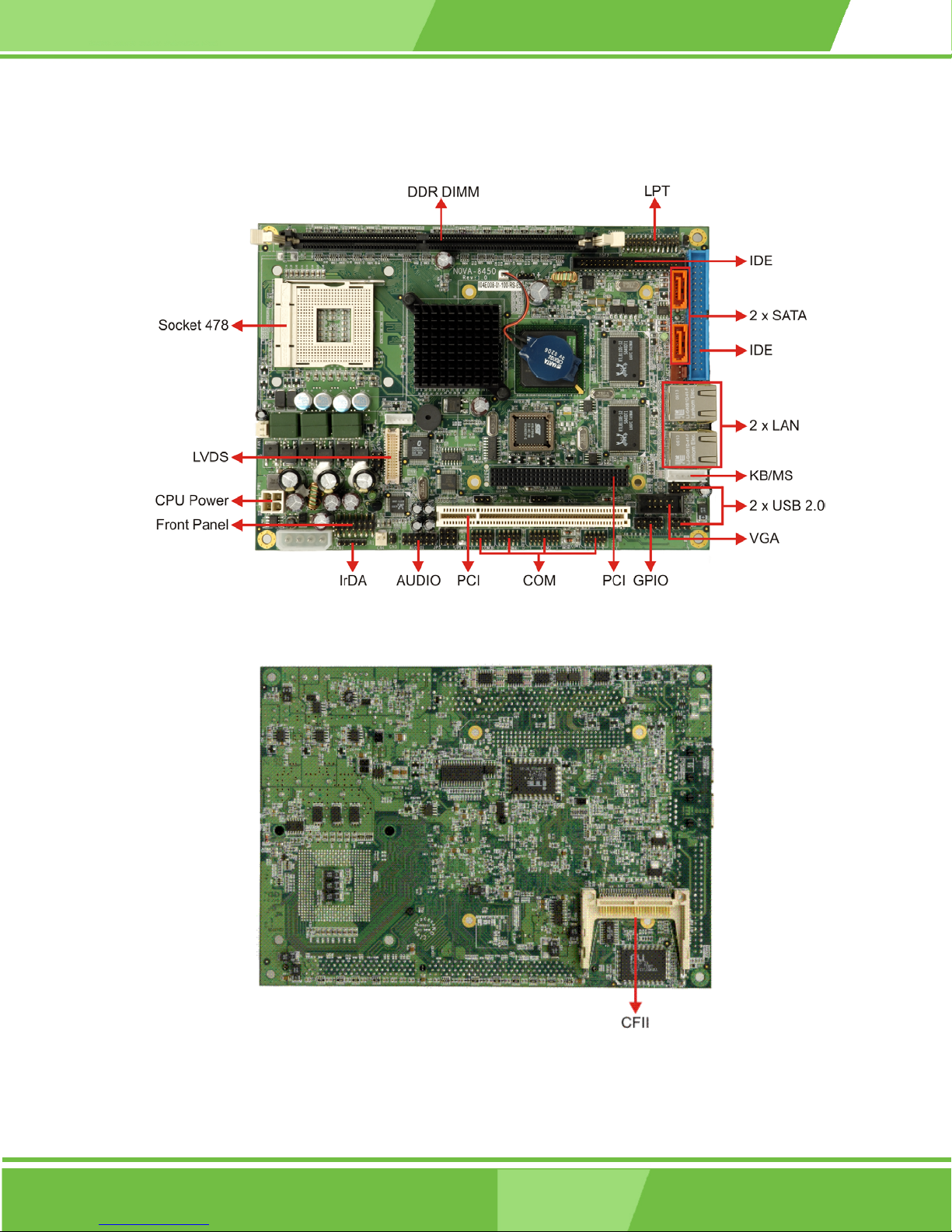
1.2 NOVA-8450 CPU Card Overview
NOVA-8450 CPU Card
Figure 1-1: NOVA-8450 CPU Card Overview (Front Side)
Figure 1-2: NOVA-8450 CPU Card Overview (Solder Side)
17
Page 18

1.2.1 NOVA-8450 CPU Card Connectors
The NOVA-8450 CPU card has the following connectors onboard:
1 x ATX 12V Connector
1 x 12V/5V External Power Connector
1 x CPU Cooling Fan Connector
1 x CFII Type Compact Flash Connector (Solder Side)
1 x Audio Connector
2 x USB Connectors
1 x IrDA Connector
2 x IDE Device Connectors
1 x Front Panel Connector
3 x RS-232 Connectors
1 x RS-232/422/485 Connector
1 x LVDS Connector
1 x Inverter Connector
1 x Parallel Port Connector
2 x SATA Connectors
1 x GPIO Connector
1 x Keyboard/Mouse Connector
The NOVA-8450 CPU card has the following connector on the board rear panel:
2 x RJ-45 Ethernet connectors
The location of the connector on the CPU card can be seen in Figure 3-27. The connector
is fully described in Chapter 2.
1.2.2 Technical Specifications:
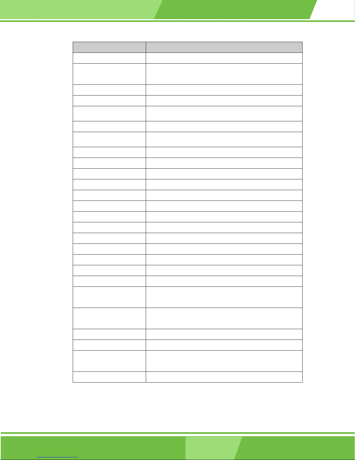
NOVA-8450 CPU card technical specifications are listed in Table 1-1. Detailed
descriptions of each specification can be found in Chapter 2.
18
IEI® Technology, Corp.
Page 19
NOVA-8450 CPU Card
SPECIFICATION
CPUs Supported Intel® Pentium® 4/Intel® Celeron® D
Chipsets
Graphics Support Intel® Extreme Graphic Integrated Graphic Engine
Memory One DDR memory module (Max. 1GB)
PCI Bus Interface
I/O Controller ICH4
Super I/O
BIOS AMI flash BIOS
Watchdog Timer Software programmable supports 1~255 sec. system reset
Ethernet Realtek RTL8110S GbE
Serial ATA (SATA) Two SATA channels with 1.5Gb/s transfer rates
HDD Interface Two IDE channels supports two Ultra ATA 100 devices
Floppy Disk Drive (FDD) Supports FDD
Northbridge: Intel® 845GV
Southbridge: Intel® ICH4
33MHz, Revision 2.2
ITE IT8712F-A/IXS
Serial Ports 4 COM ports
PCI-104 Interface PCI-104 Expansion Module
PCI Interface PCI Slot Expansion Module
USB Interfaces Four USB 2.0 connectors supported
Infrared Support One Infrared Data Association (IrDA) interface
Audio Interfaces One Audio Codec ’97 (AC’97) version 2.3 connector
Power Support AT/ATX power support
Intel Pentium 4 2.8G, DDR266/256MB
Power Management Supports Advanced Configuration and Power Interface
(ACPI) Specifications Revision 2.0
Hardware Monitoring Cooling fan, temperature and system voltages
Real Time Clock 256-byte battery backed CMOS RAM
Operating Temperature Minimum: 0ºC (32°F)
Maximum: 60°C (140°F)
Physical Dimensions 203.20mm x 146.05mm (width x length)
Table 1-1: Technical Specifications
19
Page 20

THIS PAGE IS INTENTIONALLY LEFT BLANK
20
IEI® Technology, Corp.
Page 21

NOVA-8450 CPU Card
2
Chapter
2
Detailed Specifications
21
Page 22
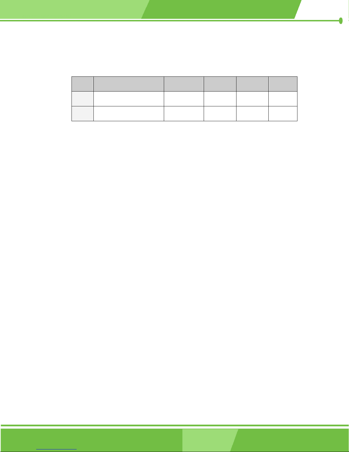
2.1 CPU Support
Table 2-1 lists the CPUs supported by the NOVA-8450 CPU card.
Mfg. Model Max. Speed L2 Cache Max. FSB Socket
Intel®
Intel®
Table 2-1: Supported CPUs
2.1.1 Intel® Pentium® 4
The Intel® Pentium® 4 CPU comes with the following features:
Pentium® 4 2.8GHz 512KB 533MHz 478
Celeron® D 2.8GHz 256KB 533MHz 478
Hyper-Threading Technology (HT Technology) ensures greater
performance
SpeedStep® Technology improves overall system power management
Execute Disable Bit technology prevents certain classes of malicious
"buffer overflow" attacks when combined with a supporting operating
system.
2.1.2 Intel® Celeron® D
22
The Intel® Celeron® D CPU comes with the following features:
Advanced Dynamic Execution Technology keeps the execution units
executing instructions
Intel® Streaming SIMD Extensions accelerates 3D graphics performance
Execute Disable Bit Technology prevents certain classes of malicious
"buffer overflow" attacks when combined with a supporting operating
system.
IEI® Technology, Corp.
Page 23
NOVA-8450 CPU Card
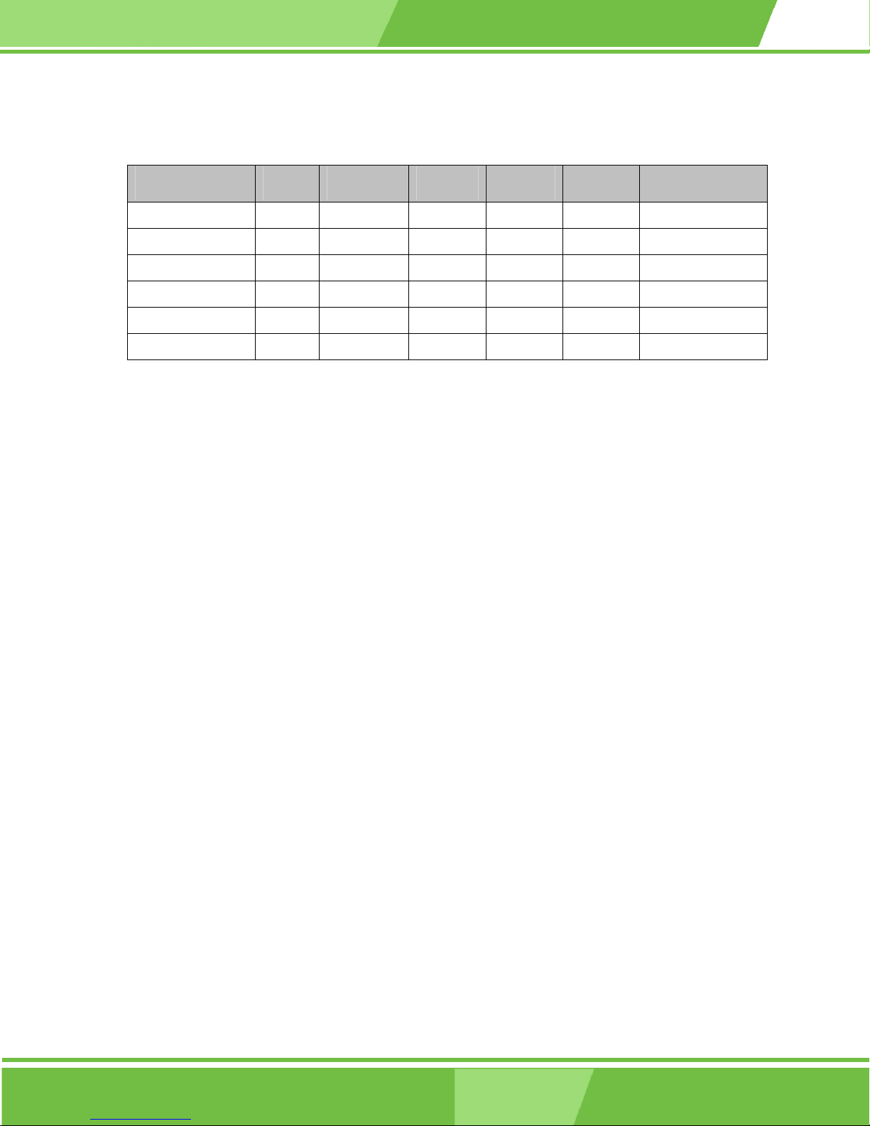
Table 2-2 lists the Intel® Celeron® D processors supported by the NOVA-8450 CPU card.
Processor Number Power Architecture L2 Cache Speed FSB Execute Disable Bit
335 Normal 90 nm 256 KB 2.80 GHz 533 MHz No
330 Normal 90 nm 256 KB 2.66 GHz 533 MHz No
325 Normal 90 nm 256 KB 2.53 GHz 533 MHz No
320 Normal 90 nm 256 KB 2.40 GHz 533 MHz No
315 Normal 90 nm 256 KB 2.26 GHz 533 MHz No
310 Normal 90 nm 256 KB 2.13 GHz 533 MHz No
Table 2-2: Supported Celeron® D CPUs
2.2 Onboard Chipsets
2.2.1 Northbridge and Southbridge Chipsets
The following chipsets are preinstalled on the card:
Northbridge: 845GV
Southbridge: ICH4
The following two sections (Section 2.2.2 and Section 2.2.3) list some of the features of
the 845GV and the ICH4 chipsets. For more information on these two chipsets please refer
to the Intel® website.
2.2.2 845GV Northbridge Chipset
The 845GV northbridge chipset comes with the following features:
Host Interface Support
System Memory Controller (SDR and DDR)
AGP Interface
Integrated Graphics
Analog Display Support
Digital Display Channels
23
Page 24

2.2.3 ICH4 Southbridge Chipset
The ICH4 southbridge chipset comes with the following features:
PCI Bus Interface
Integrated LAN Controller
Integrated IDE Controller
USB 2.0
AC-Link for Audio and Telephony CODECs
Interrupt Controller
1.5 V operation with 3.3 V I/O
Timers Based on 82C54
Power Management Logic
External Glue Integration
Enhanced Hub Interface Buffers Improve Routing flexibility (Not available
with all Memory Controller Hubs)
Firmware Hub (FWH) Interface Supports BIOS memory size up to 8 MB
Low Pin Count (LPC) Interface
Enhanced DMA Controller
Real-Time Clock
System TCO Reduction Circuits
SMBus
GPIO
24
IEI® Technology, Corp.
Page 25
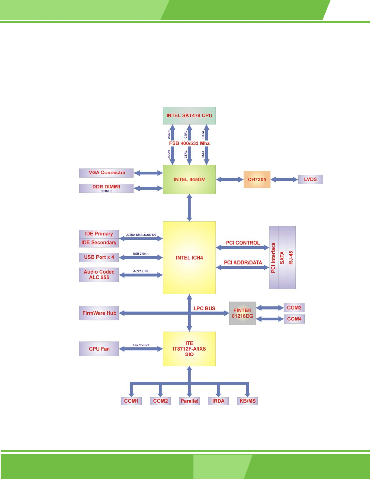
2.3 Data Flow
Figure 2-1 shows the data flow between the two onboard chipsets and other components
installed on the CPU card and described in the following sections of this chapter.
NOVA-8450 CPU Card
Figure 2-1: Data Flow Block Diagram
25
Page 26

2.4 Graphics Support
The graphics features listed below are all integrated on the 845GV northbridge chipset.
3D Setup and Render Engine
o Discrete Triangles, Strips and Fans Support
o Indexed Vertex and Flexible Vertex Formats
o Pixel Accurate Fast Scissoring and Clipping Operation
o Backface Culling Support
o Supports D3D and OGL Pixelization Rules
o Anti-Aliased Lines Support
o Sprite Points Support
High Quality Texture Engine
o Per Pixel Perspective Corrected Texture Mapping
o Single Pass Texture Compositing (Multi-Textures) at rate
o 12 Levels of Detail MIP Map Sizes from 1x1 to 2Kx2K
o All texture formats including 32-bit RGBA
o Alpha and Luminance Maps
o Texture ChromaKeying
o Bilinear, Trilinear, and Anisotropic MIPMapped Filtering
o Cubic Environment Reflection Mapping
o Embossed Bump-Mapping
o DOT3-based Bump-Mapping
o DXTn Texture Decompression
o FXT1 Texture Decompression
3D Graphics Rasterization Enhancements
o 200 MegaPixel/Sec Fill Rate
o Flat and Gouraud Shading
o Color Alpha Blending for Transparency
o Vertex and Programmable Pixel Fog and Atmospheric Effects
o Color Specular Lighting
o Z Bias Support
o Dithering
o Anti-Aliasied Lines
o 16- and 24-bit Z Buffering
o 16- and 24-bit W Buffering
26
IEI® Technology, Corp.
Page 27

NOVA-8450 CPU Card
o 8-bit Stencil Buffering
o Double and Triple Render Buffer Support
o 16- and 32-bit Color
o Destination Alpha
o Maximum 3D Resolution Supported: 1600x1200x32 at 85 Hz
o Fast Clear Support
2D Graphics
o Optimized 256-bit BLT Engine
o GDI+* Feature Support
o Alpha Stretch Blitter
o Anti-Aliased Lines
o 32-bit Alpha Blended Cursor
o Programmable 3-Color Transparent Cursor
o Color Space Conversion
o 8-, 16- and 32-bit Color
o ROP Support
Video DVD/PC-VCR
o Dynamic Bob and Weave Support for Video Streams
o Synclock Display and TV-out to video source
o Source Resolution: up to 720x480 with 2-vertical taps
o Software DVD at 30 fps, Full Screen
Video Overlay
o Single Scalable Overlay
o Multiple Overlay Functionality provided via Stretch Blitter (PIP, Video
Conferencing, etc.)
o 5-tap Horizontal, 2-tap Vertical Filtered Scaling
o Independent Gamma Correction
o Independent Brightness/Contrast/Saturation
o Independent Tint/Hue Support
o Destination Color-keying
o Source Chroma-keying
o Maximum Source Resolution: 720x480 (576) Maximum Overlay
Display Resolution: 1600x1200x32 at 60 Hz and
1280x1024x32 at 85 Hz
27
Page 28

2.5 Memory Support
The NOVA-8450 CPU has one 184-pin dual inline memory module (DIMM) socket and
supports an un-buffered DDR DIMM with the following specifications:
Maximum RAM: 1GB
DIMM Transfer Rates: 333MHz
2.6 PCI Bus Interface Support
The PCI bus on the NOVA-8450 CPU card has the following features:
33MHz Revision 2.2 is implemented
Maximum throughput: 133MB/sec based on the ICH4 chipset
Master devices: Maximum of six with three implemented
One PCI REQ/GNT pair can be given higher arbitration priority (intended
for external 1394 host controller)
44-bit addressing using the DAC protocol supported
2.7 Super I/O
The ITE IT8712F is a Low Pin Count Interface-based highly integrated Super I/O. The
IT8712F provides the most commonly used legacy Super I/O functionality plus the latest
Environment Control initiatives, such as H/W Monitor, Fan Speed Controller, ITE’s
“SmartGuardian” function and Smart Card Reader Interface. The device’s LPC interface
complies with Intel “LPC Interface Specification Rev. 1.0”. The IT8712F is ACPI &
LANDesk compliant.
Low Pin Count Interface
o Comply with Intel Low Pin Count Interface Specification Rev. 1.0
o Supports LDRQ#, SERIRQ protocols
o Supports PCI PME# Interfaces
ACPI & LANDesk Compliant
o ACPI V. 1.0 compliant
o Register sets compatible with “Plug and Play ISA Specification V.
o LANDesk 3.X compliant
28
1.0a”
IEI® Technology, Corp.
Page 29

NOVA-8450 CPU Card
o Supports 12 logical devices
Enhanced Hardware Monitor
o Built-in 8-bit Analog to Digital Converter
o 3 thermal inputs from remote thermal resistor or thermal diode or
diode-connected transistor
o 8 voltage monitor inputs (VBAT is measured internally.)
o 1 chassis open detection input with low power Flip-Flop backed by
the battery
o Watch Dog comparison of all monitored values
o Provides VID0 – VID5 support for the CPU
Fan Speed Controller
o Provides fan on-off and PWM control
o Supports 5 programmable Pulse Width
o Modulation (PWM) outputs
o 128 steps of PWM modes
o Monitors 5 fan tachometer inputs
SmartGuardian Controller
o Provides programmable fan speed automatic control
o Supports mix-and-match for temperature inputs and fan speed control
outputs
o Overrides fan speed controller during catastrophic situations
o Provides over temperature beep tone warning
Two 16C550 UARTs
o Supports two standard Serial Ports
o Supports IrDA 1.0/ASKIR protocols
o Supports Smart Card Reader protocols
Smart Card Reader
o Compliant with Personal Computer Smart Card (PC/SC) Working
Group standard
o Compliant with smart card (ISO 7816) protocols
o Supports card present detect
o Supports Smart Card insertion power-on feature
o Supports one programmable clock frequency, and 7.1 MHz and 3.5
Consumer Remote Control (TV remote) IR with power-up feature
IEEE 1284 Parallel Port
MHz (Default) card clocks
29
Page 30

o Standard mode -- Bi-directional SPP compliant
o Enhanced mode -- EPP V. 1.7 and V. 1.9 compliant
o High speed mode -- ECP, IEEE 1284 compliant
o Back-drive current reduction
o Printer power-on damage reduction
o Supports POST (Power-On Self Test) Data Port
Floppy Disk Controller
o Supports two 360K/ 720K/ 1.2M/ 1.44M/ 2.88M floppy disk drives
o Enhanced digital data separator
o 3-Mode drives supported
o Supports automatic write protection via software
Keyboard Controller
o 8042 compatible for PS/2 keyboard and mouse
o 2KB of custom ROM and 256-byte data RAM
o GateA20 and Keyboard reset output
o Supports any key, or 2-5 sequential keys, or 1-3 simultaneous keys
keyboard power-on events
o Supports mouse double-click and/or mouse move power on events
o Supports Keyboard and Mouse I/F hardware auto-swap
Game Port
o Built-in 558 quad timers and buffer chips
o Supports direct connection of two joysticks
Dedicated MIDI Interface
o MPU-401 UART mode compatible
38 General Purpose I/O Pins
o Input mode supports either switch de-bounce or programmable
external IRQ input routing
o Output mode supports 2 sets of programmable LED blinking periods
External IRQ Input Routing Capability
o Provides IRQ input routing through GPIO input mode
o Programmable registers for IRQ routing
Watch Dog Timer
o Time resolution 1 minute or 1 second, maximum 255 minutes or 255
o Output to KRST# when expired
ITE innovative automatic power-failure resume and power button
30
seconds
IEI® Technology, Corp.
Page 31
2.8 BIOS
The NOVA-8450 CPU card uses a licensed copy of AMI BIOS. Flash BIOS features used
are listed below:
NOVA-8450 CPU Card
de-bounce
Dedicated Infrared pins
VCCH and Vbat Supported
Built-in 32.768 KHz Oscillator
Single 24/48 MHz Clock Input
+5V Power Supply
SMIBIOS (DMI) compliant
Console redirection function support
PXE (Pre-Boot Execution Environment) support
USB booting support
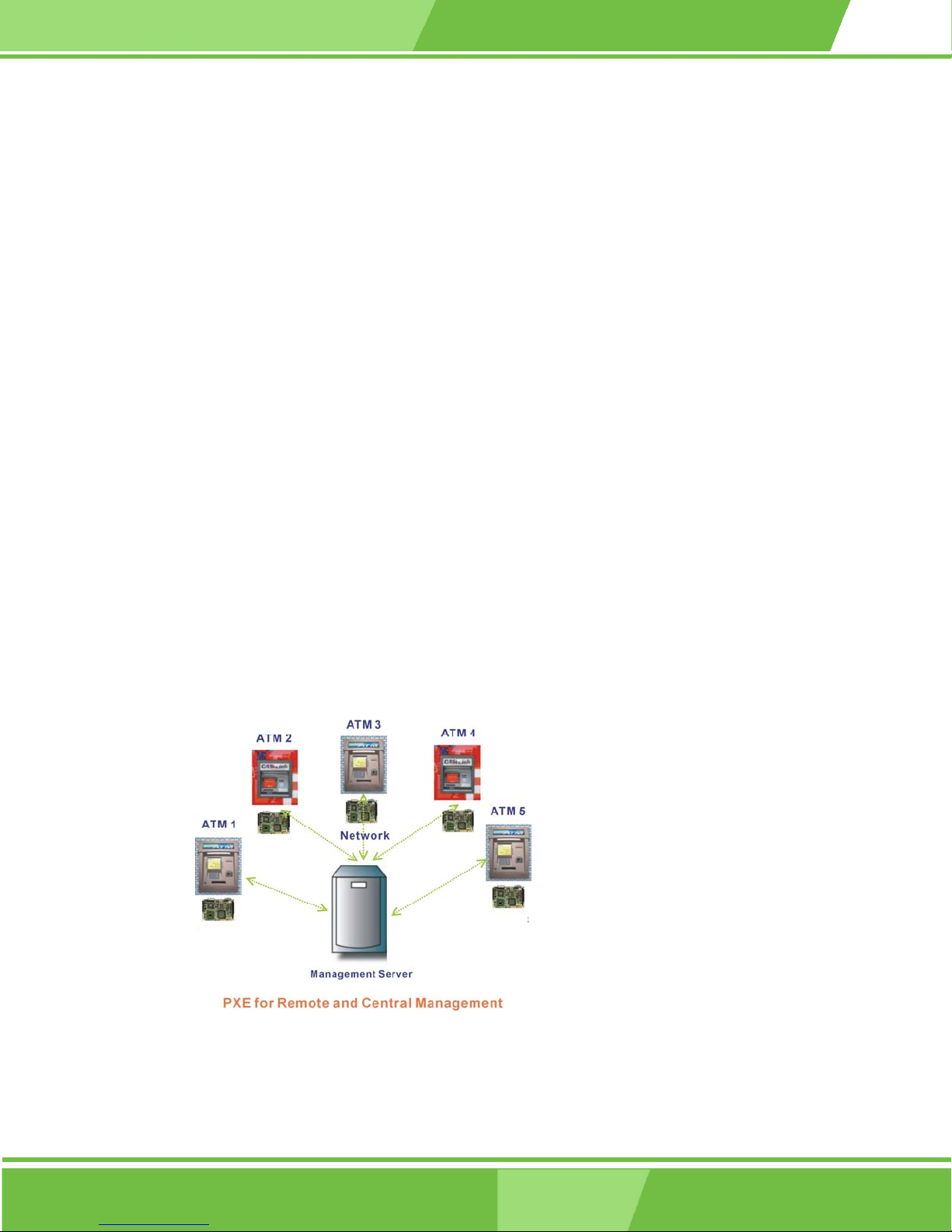
2.9 PXE: Pre-Boot Execution Environment
PXE is an open industry standard developed by a number of software and hardware
vendors. IEI BIOS PXE feature allows a workstation to boot from a server on a network by
receiving a pre-OS agent prior to booting the operating system on the local hard drive.
NOVA-8540
NOVA-8540
NOVA-8540
NOVA-8540
NOVA-8540
Figure 2-2: PXE: Pre-Boot Execution Environment
31
Page 32

2.10 GbE Ethernet
The Realtek RTL8110SC GbE controller combines a triple-speed IEEE 802.3 compliant
Media Access Controller (MAC) with a triple-speed Ethernet transceiver, 32-bit PCI bus
controller, and embedded memory. The controller has state-of-the-art DSP technology and
mixed-mode signal technology and it offers high-speed transmission over CAT 5 UTP
cables or CAT 3 UTP (10Mbps only) cables. The GbE controller specifications are below.
Integrated 10/100/1000 transceiver
Auto-Negotiation with Next Page capability
Supports PCI rev.2.3, 32-bit, 33/66MHz
Supports pair swap/polarity/skew correction
Crossover Detection & Auto-Correction
Wake-on-LAN and remote wake-up support
Microsoft® NDIS5 Checksum Offload (IP, TCP, UDP) and largesend
offload support
Supports Full Duplex flow control (IEEE 802.3x)
Fully compliant with IEEE 802.3, IEEE 802.3u, IEEE 802.3ab
Supports IEEE 802.1P Layer 2 Priority Encoding
Supports IEEE 802.1Q VLAN tagging
Serial EEPROM
3.3V signaling, 5V PCI I/O tolerant
Transmit/Receive FIFO (8K/64K) support
Supports power down/link down power saving
Supports PCI Message Signaled Interrupt (MSI)
2.11 Drive Interfaces
The NOVA-8450 can support the following drive interfaces.
2 x SATA drives
2 x IDE devices
32
IEI® Technology, Corp.
Page 33

2.11.1 SATA Drives
The NOVA-8450 CPU card supports two first generation SATA drives with transfer rates up
to 1.5 Gb/s.
2.11.2 IDE HDD Interfaces
The NOVA-8450 southbridge chipset IDE controller supports up to two HDDs with the
following specifications:
Supports PIO IDE transfers up to 16 MB/s
Supports 8237 style DMA protocol with transfer rates of up to 16 MB/s
Supports the following Ultra ATA device:
o Supports an Ultra ATA/100/66/33 DMA protocol with data transfer
NOVA-8450 CPU Card
rates up to 100 MB/s
2.12 Serial Ports
The NOVA-8450 CPU card has four high-speed UART serial ports, configured as COM1
through COM4. The serial ports have the following specifications.
16C550 UART with 16-byte FIFO buffer
115.2Kbps transmission rate
2.13 PCI Interfaces
The NOVA-8450 offers two (2) PCI interfaces:
PCI-104 Expansion Module
PCI Slot Expansion Module
2.14 USB Interfaces
The NOVA-8450 CPU card has 2 USB 2.0 connectors for 4 USB devices.
2.15 Infrared Data Association (IrDA) Interface
The NOVA-8450 CPU card IrDA supports the following interfaces.
33
Page 34

Serial Infrared (SIR)
Shift Keyed Infrared (ASKIR)
To use the IrDA port, configure SIR or ASKIR mode in the BIOS under Super IO devices.
The normal RS-232 COM 2 will then be disabled.
2.16 Audio Codec
The NOVA-8450 has an integrated REALTEK ALC655 CODEC. The ALC655 CODEC is a
16-bit, full-duplex AC'97 Rev. 2.3 compatible six-channel audio CODEC designed for PC
multimedia systems, including host/soft audio and AMR/CNR-based designs. Some of the
features of the codec are listed below.
Meets performance requirements for audio on PC99/2001 systems
Meets Microsoft WHQL/WLP 2.0 audio requirements
16-bit Stereo full-duplex CODEC with 48KHz sampling rate
Compliant with AC'97 Rev 2.3 specifications
Front-Out, Surround-Out, MIC-In and LINE-In Jack Sensing
14.318MHz -> 24.576MHz PLL to eliminate crystal
12.288MHz BITCLK input
Integrated PCBEEP generator to save buzzer
Interrupt capability
Three analog line-level stereo inputs with 5-bit volume control, LINE_IN,
CD, AUX
High-quality differential CD input
Two analog line-level mono inputs: PCBEEP, PHONE-IN
Two software selectable MIC inputs
Dedicated Front-MIC input for front panel applications (software
selectable)
Boost preamplifier for MIC input
LINE input shared with surround output; MIC input shared with Center
and LFE output
Built-in 50mW/20ohm amplifier for both Front-out and Surround-Out
External Amplifier Power Down (EAPD) capability
Power management and enhanced power saving features
Supports Power-Off CD function
34
IEI® Technology, Corp.
Page 35
NOVA-8450 CPU Card
Adjustable VREFOUT control
Supports 48KHz S/PDIF output, complying with AC'97 Rev 2.3
specifications
Supports 32K/44.1K/48KHz S/PDIF input
Power support: Digital: 3.3V; Analog: 3.3V/5V
Standard 48-pin LQFP package
EAX™ 1.0 & 2.0 compatible
Direct Sound 3D™ compatible
A3D™ compatible
I3DL2 compatible
HRTF 3D positional audio
10-band software equalizer
Voice cancellation and key shifting in Karaoke mode
AVRack® Media Player
Configuration Panel for improved user convenience
2.17 Power Consumption
Table 2-3 shows the power consumption parameters for the NOVA-8450 CPU card when a
Intel® Pentium® 4/Intel® Celeron® D processor with a clock speed of 2.4GHz, an L2
cache of 256MB and a FSB 533MHz is running with a 1GB DDR266 module.
Voltage Current
+5V 2.9A
+12V 3.5A
Table 2-3: Power Consumption
2.18 System Monitoring
The NOVA-8450 CPU card is capable of self-monitoring various aspects of its operating
status including:
CPU, chipset, and battery voltage, +3.3V, +5V, and +12V
RPM of cooling fans
CPU and card temperatures (by the corresponding embedded sensors)
35
Page 36

2.19 Real Time Clock
256-byte battery backed CMOS RAM
2.20 Operating Temperature and Temperature Control
The maximum and minimum operating temperatures for the NOVA-8450 CPU card are
listed below.
Minimum Operating Temperature: 0ºC (32°F)
Maximum Operating Temperature: 60°C (140°F)
A cooling fan and heat sink must be installed on the CPU. Thermal paste must be smeared
on the lower side of the heat sink before it is mounted on the CPU. Heat sinks are also
mounted on the northbridge and southbridge chipsets to ensure the operating temperature
of these chips remain low.
2.21 Packaged Contents and Optional Accessory Items
2.21.1 Package Contents
The NOVA-8450 CPU card, comes with the following components:
1 x NOVA-8450 single board computer
1 x ATA66/100 HDD cable
1 x ATA33 HDD cable
1 x Keyboard/ PS2 mouse cable
2 x SATA cable
1 x SATA Power cable
3 x RS232 cable
1 x RS232/422/485 cable
1 x Audio cable
1 x USB cable
1 x VGA cable
1 x ATX 12V power cable
36
IEI® Technology, Corp.
Page 37

1 x mini jumper pack
1 x Utility CD
1 x QIG (quick installation guide)
2.21.2 Optional Accessory Items
The items shown in the list below are optional accessory items purchased separately.
Socket 478 type CPU Cooler
LPT cable
NOVA-8450 CPU Card
37
Page 38

THIS PAGE IS INTENTIONALLY LEFT BLANK
38
IEI® Technology, Corp.
Page 39

NOVA-8450 CPU Card
3
Chapter
3
Connectors and Jumpers
39
Page 40
3.1 Peripheral Interface Connectors
The locations of the peripheral interface connectors are shown in Section 3.1.1. A
complete list of all the peripheral interface connectors can be seen in Section 3.1.2.
3.1.1 NOVA-8450 CPU Card Layout
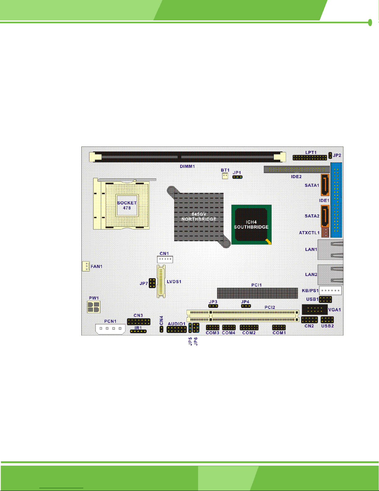
Figure 3-1 shows the onboard peripheral connectors, backplane peripheral connectors
and onboard jumpers on the front side of the card.
Figure 3-1: Connector and Jumper Locations (Front Side)
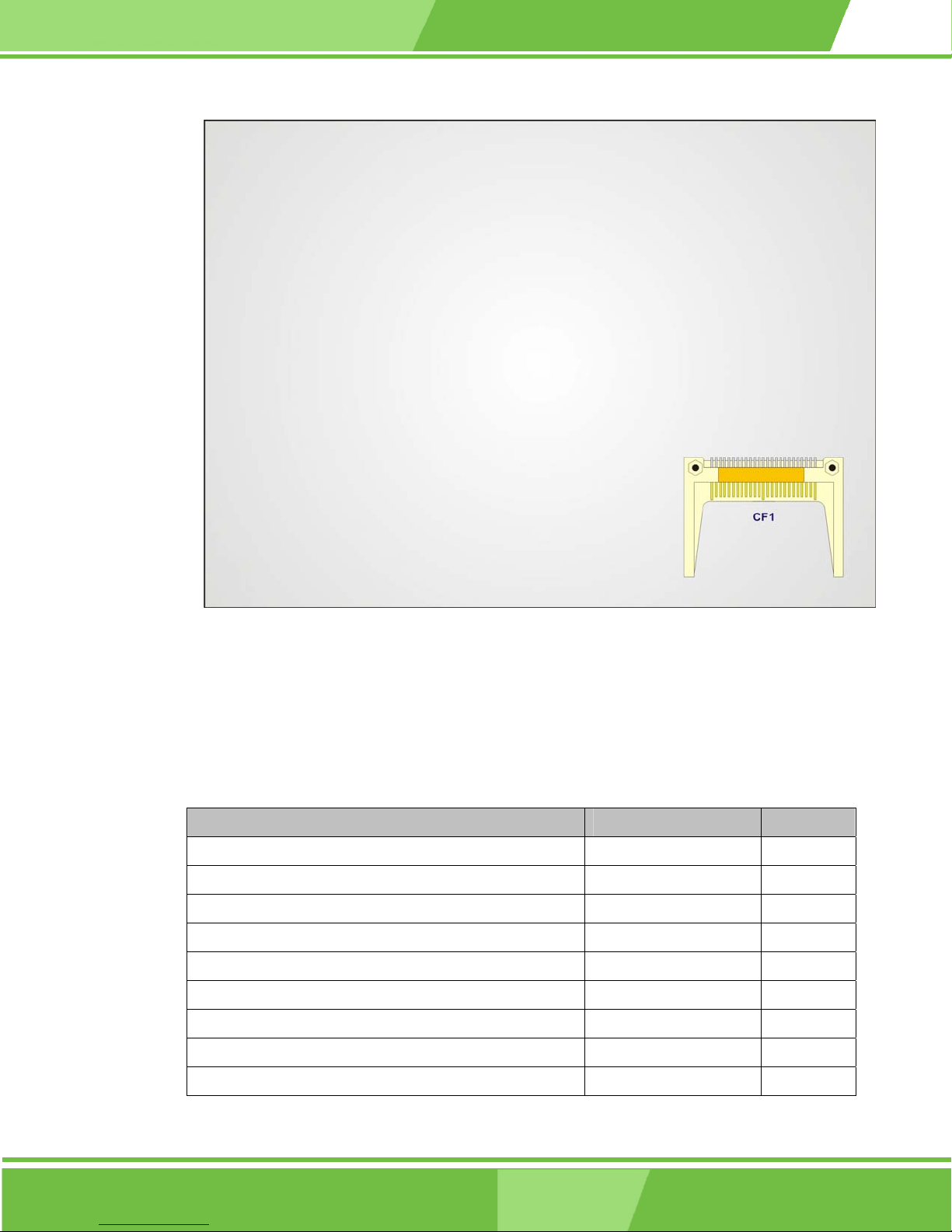
Figure 3-2 shows the onboard peripheral connectors on the solder side of the board.
40
®
IEI
Technology, Corp.
Page 41
NOVA-8450 CPU Card
Figure 3-2: Connector and Jumper Locations (Solder Side)
3.1.2 Peripheral Interface Connectors
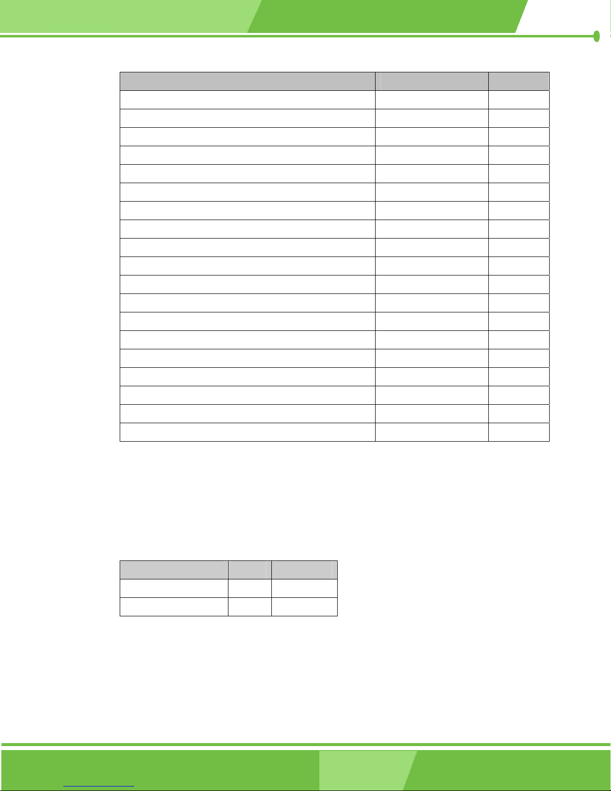
Table 3-1 shows a list of the peripheral interface connectors on the NOVA-8450 CPU card.
Detailed descriptions of these connectors can be found in Section 3.2.
Connector Type Label
8 Bit GPIO Connector 10-pin header CN2
ATX 12V Connector 4-pin header PW1
ATX Power On Switch Connector 2-pin header CN4
Audio Connector 12-pin header AUDIO1
ATX Connector 3-pin header ATXCTL1
Battery Connector 2-pin header BT1
Compact Flash Type II Connector 50-pin header CF1
CPU Cooling Fan Connector 3-pin header FAN1
External Power Connector 4-pin header PCN1
41
Page 42
Connector Type Label
Front Panel Connector 14-pin header CN3
IDE Interface Connector (Primary) 40-pin header IDE1
IDE Interface Connector (Secondary) 44-pin header IDE2
Inverter Connector 5-pin header CN1
IrDA Connector 5-pin header IR1
Keyboard/Mouse Connector 6-pin header KB/PS1
LVDS LCD Panel Connector 30-pin header LVDS1
Parallel Port Connector 26-pin header LPT1
PCI Connector PCI-104 PCI1
PCI Connector PCI Slot PCI2
SATA Drive Port (150MB/S) SATA disk drive port SATA1
SATA Drive Port (150MB/S) SATA disk drive port SATA2
RS-232 Serial Communications Connector 10-pin header COM1
RS-232/422/485 Serial Communications Connector 14-pin header COM2
RS-232 Serial Communications Connector 10-pin header COM3
RS-232 Serial Communications Connector 10-pin header COM4
USB Connector for 2 USB Devices 8-pin header USB1
USB Connector for 2 USB Devices 8-pin header USB2
VGA Connector 10-pin header VGA1
Table 3-1: Peripheral Interface Connectors
3.1.3 Rear Panel Connectors
Table 3-2 lists the rear panel connectors on the NOVA-8450 CPU card. Detailed
descriptions of the connectors can be found in Section 4.6.
Connector Type Label
Ethernet connector RJ-45 LAN1
Ethernet connector RJ-45 LAN2
Table 3-2: Peripheral Interface Connectors
42
IEI® Technology, Corp.
Page 43
3.1.4 Onboard Jumpers
Table 3-3 lists the onboard jumpers. Detailed descriptions of these jumpers can be found in
Section 3.4.
Connector Type Label
Clear CMOS Setup 3-pin header JP1
COM2 RS-232/422/485 Setup 3-pin header JP4
COM2 RS-422/485 Setup 3-pin header JP5
COM2 Voltage Selection 6-pin header JP6
Compact Flash Card Setup 2-pin header JP2
LCD Panel (LVDS) Voltage select 6-pin header JP7
PC104 Plus VIO Voltage Setup 3-pin header JP3
NOVA-8450 CPU Card
Table 3-3: Onboard Jumpers
3.2 Internal Peripheral Connectors
Internal peripheral connectors on the CPU card are only accessible when the CPU card is
outside of the chassis. This section has complete descriptions of all the internal, peripheral
connectors on the NOVA-8450 CPU card.
3.2.1 Bit GPIO Connector
CN Label: CN2
CN Type: 10-pin header (2x5 pins)
CN Location: See Figure 3-3
CN Pinouts: See Table 3-4
The General Purpose Input/Output (GPIO) connector is a user-programmable
general-purpose I/O controller. The GPIO connector is managed through an ITE
IT8712F-A/IXS SI/O chip.
43
Page 44
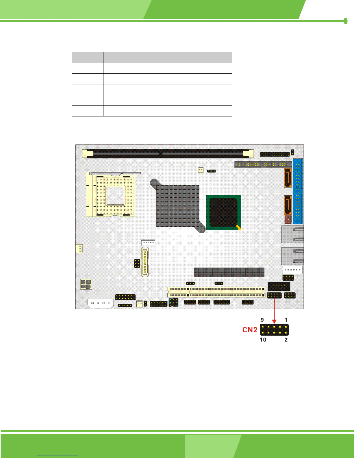
PIN NO. DESCRIPTION PIN NO. DESCRIPTION
1 GND 2 VCC5
3 GPO3 4 GPO2
5 GPO1 6 GPO0
7 GPI3 8 GPI2
9 GPI1 10 GPI0
Table 3-4: CN2 Connector Pinouts
Figure 3-3: CN2 Connector Location
44
®
IEI
Technology, Corp.
Page 45
3.2.2 ATX-12V Power Source Connector
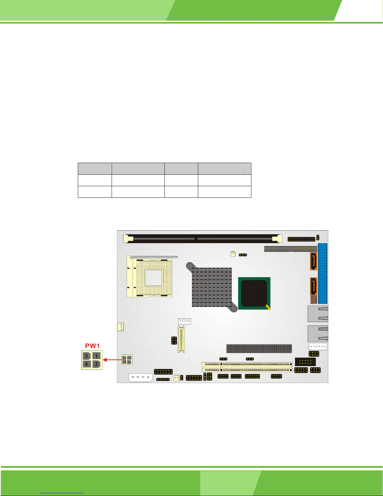
CN Label: PW1
CN Type: 4-pin header (2x2 pins)
CN Location: See Table 3-5
CN Pinouts: See Figure 3-4
This connector supports the ATX-12V power supply.
PIN NO. DESCRIPTION PIN NO. DESCRIPTION
1 GND 2 GND
3 +12V 4 +12V
NOVA-8450 CPU Card
Table 3-5: PW1 Connector Pinouts
Figure 3-4: PW1 Connector Location
45
Page 46
3.2.3 ATX Power On Switch Connector
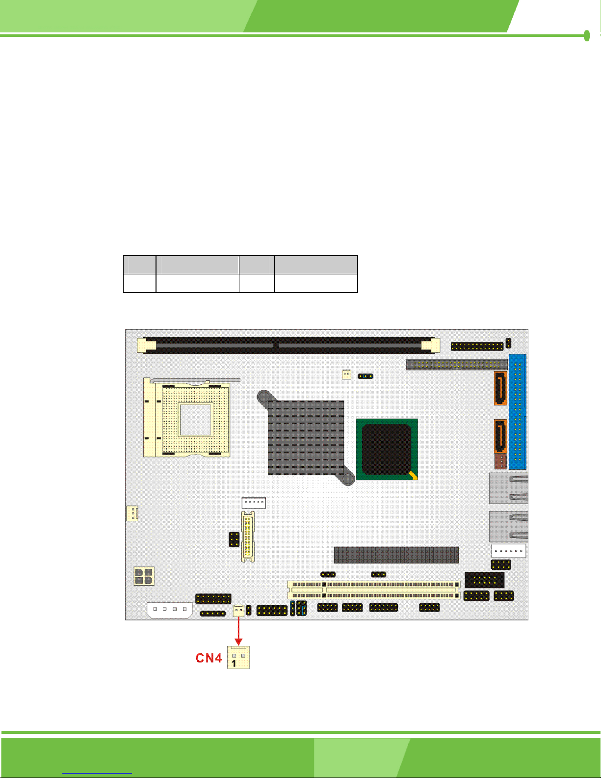
CN Label: CN4
CN Type: 2-pin header
CN Location: See Figure 3-5
CN Pinouts: See Table 3-6
The ATX Power On Switch is used to turn on the power of an ATX power supply.
PIN DESCRIPTION PIN DESCRIPTION
1 PANSWIN 2 GND
Table 3-6: CN4 Connector Pinouts
Figure 3-5 CN4 Connector Location
46
®
IEI
Technology, Corp.
Page 47
3.2.4 Audio Connector
CN Label: AUDIO1
CN Type: 12-pin header (2x6 pins)
CN Location: See Figure 3-6
CN Pinouts: See Table 3-7
AC’97 Audio signals are interfaced through a 12-pin flat-cable connector. These signals
include Microphone line-in, line-in stereo, and line-out stereo. An audio
12-pin-to-phone-jack adapter kit is required.
PIN NO. DESCRIPTION PIN NO. DESCRIPTION
1 SPKOUT_L 2 SPKOUT_R
NOVA-8450 CPU Card
3 GND 4 GND
5 LINE_OUT_L 6 LINE_OUT_R
7 LINE_IN_L 8 LINE_IN_R
9 GND 10 GND
11 MIC_IN 12 GND
Table 3-7: AUDIO1 Connector Pinouts
47
Page 48
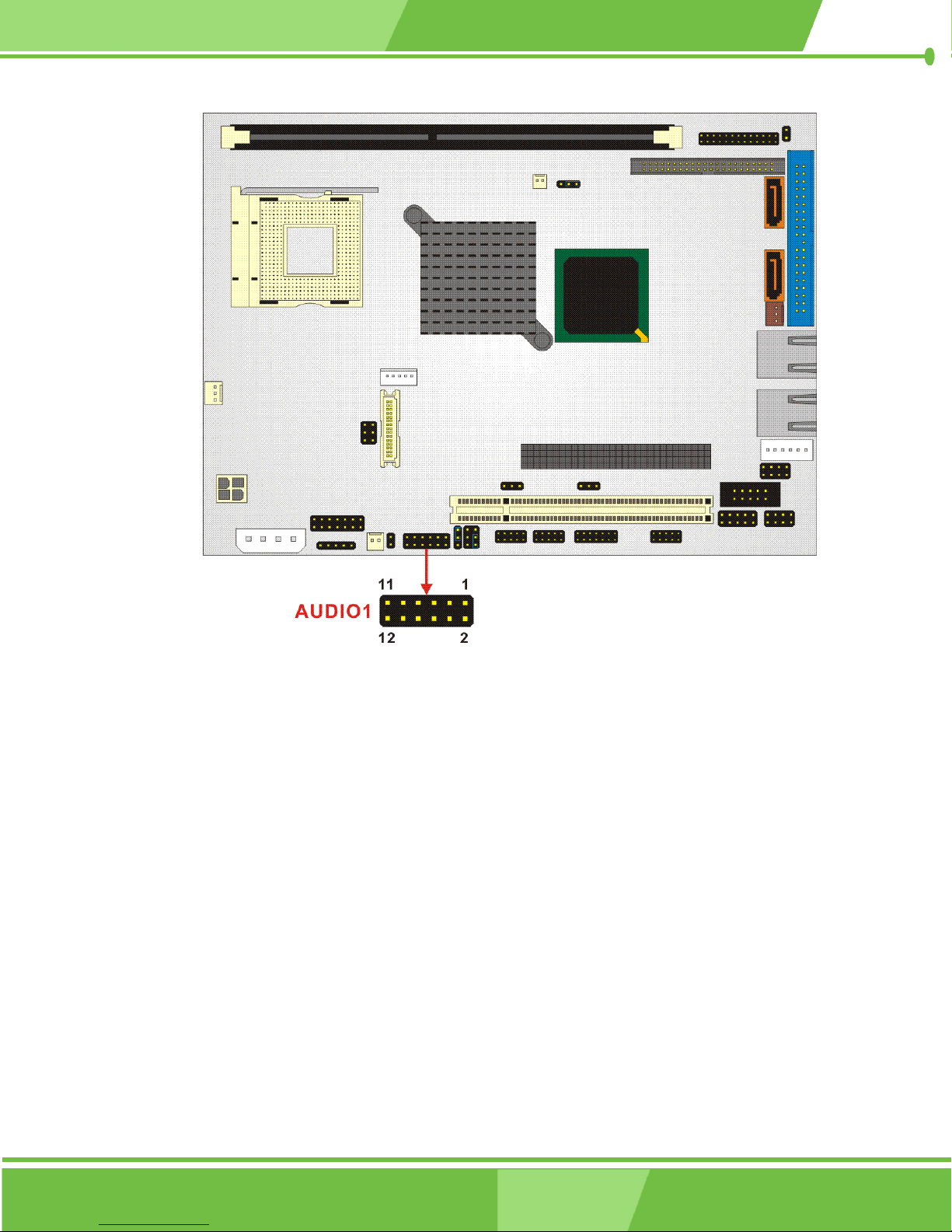
Figure 3-6: AUDIO1 Connector Location
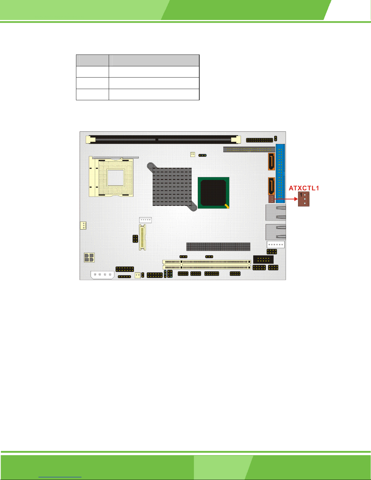
3.2.5 ATX Connector
CN Label: ATXCTL1
CN Type: 3-pin header
CN Location: See Figure 3-7
CN Pinouts: See Table 3-8
The ATX Power connector (PW1) connects an ATX or AT power supply connector.
48
®
IEI
Technology, Corp.
Page 49
NOVA-8450 CPU Card
PIN NO. DESCRIPTION
1 5VSB
2 ATX-ON
3 GND
Table 3-8: ATXCTL1 Connector Pinouts
Figure 3-7: ATXCTL1 Connector Location
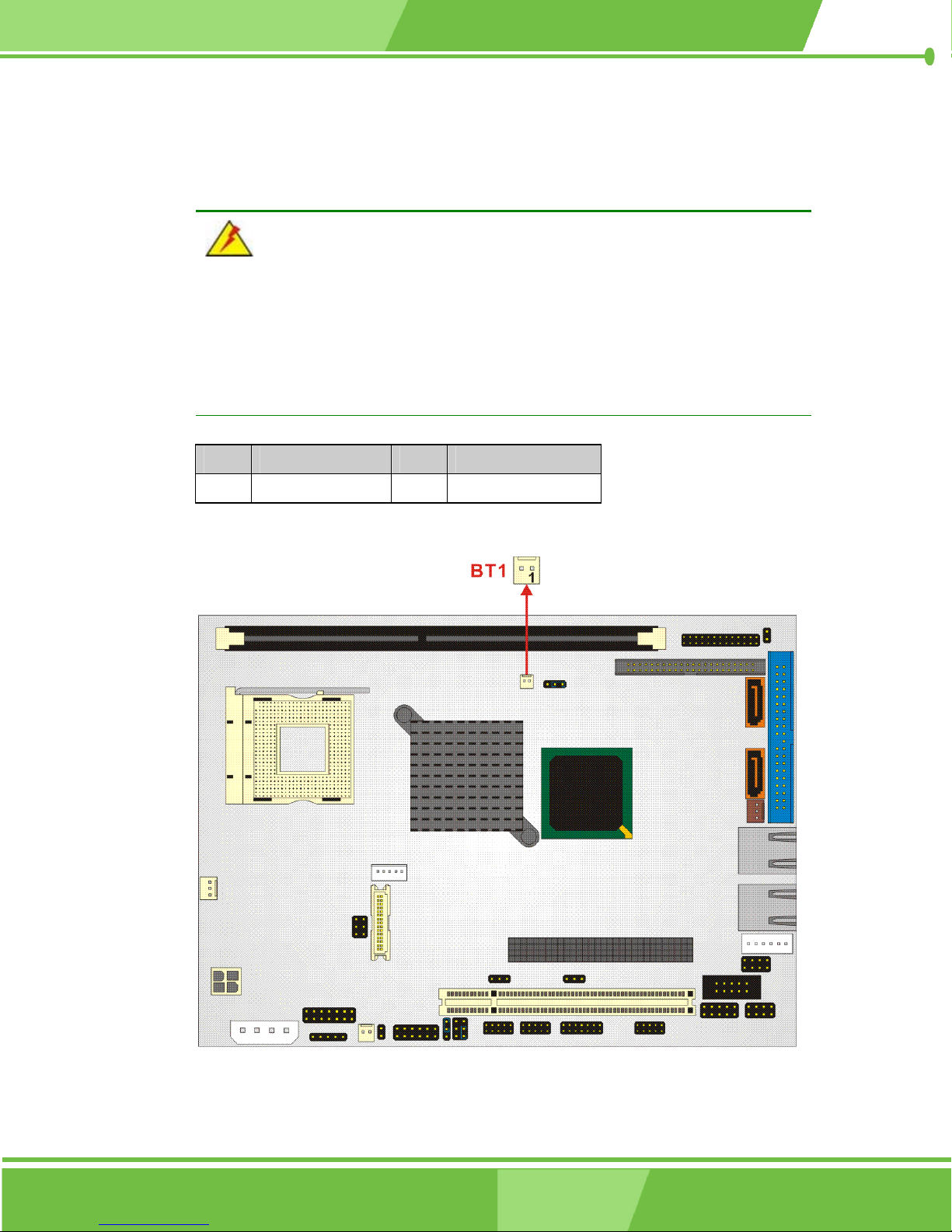
3.2.6 Battery Connector
CN Label: BT1
CN Type: 2-pin header
CN Location: See Figure 3-8
CN Pinouts: See Table 3-9
The battery connector connects to an externally mounted 3V, Lithium, cell coin battery
(VARTA CR2032). The life expectancy of the battery is approximately 7 years. Depending
on the working condition, the life expectancy may be shorter.
Replacing the battery is not a user operation.
49
Page 50
If the battery starts to weaken and lose voltage, contact a vendor or IEI for a replacement
module. Dispose of the used battery properly. Contact the local waste disposal agency for
disposal instructions. Do not dispose of a used battery with normal household waste.
WARNING!
1. Keep batteries away from children.
2. There is a danger of explosion if the battery is incorrectly replaced.
3. Only a certified module from IEI can be used as a replacement.
4. Do not expose the battery to excessive heat or fire.
5. If the battery shows signs of leakage, contact a local vendor or IEI immediately.
PIN DESCRIPTION PIN DESCRIPTION
1 BAT+ 2 GND
Table 3-9: BT1 Connector Pinouts
Figure 3-8: BT1 Connector Location
50
®
IEI
Technology, Corp.
Page 51
3.2.7 Compact Flash Connector
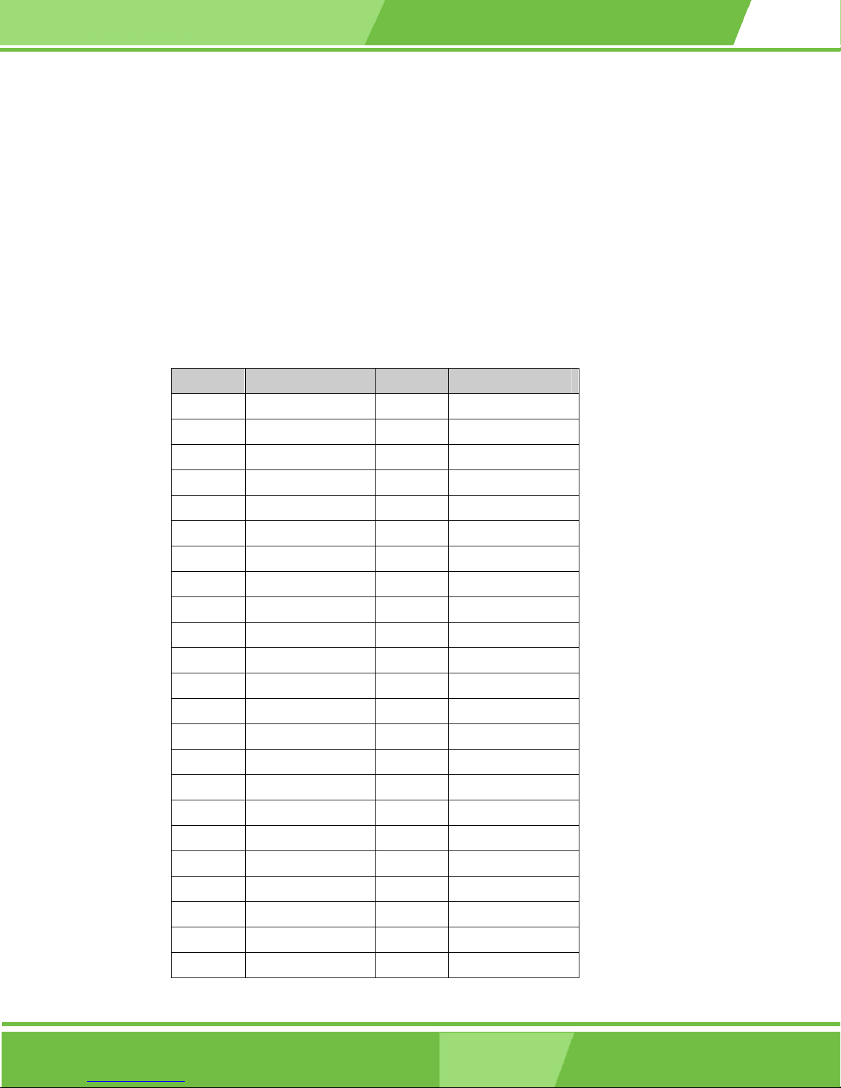
CN Label: CF1
CN Type: 50-pin header (2x25 pins)
CN Location: See Figure 3-9
CN Pinouts: See Table 3-10
The Compact Flash connector is used to adapt Type II Compact Flash and CF+ cards for
use in Type II (5 mm thick) PCMCIA card slots.
PIN NO. DESCRIPTION PIN NO. DESCRIPTION
1 GROUND 26 VCC-IN CHECK1
2 DATA 3 27 DATA 11
NOVA-8450 CPU Card
3 DATA 4 28 DATA 12
4 DATA 5 29 DATA 13
5 DATA 6 30 DATA 14
6 DATA 7 31 DATA 15
7 HDC_CS0# 32 HDC_CS1
8 N/C 33 N/C
9 GROUND 34 IOR#
10 N/C 35 IOW#
11 N/C 36 VCC_COM
12 N/C 37 IRQ15
13 VCC_COM 38 VCC_COM
14 N/C 39 CSEL
15 N/C 40 N/C
16 N/C 41 HDD_RESET
17 N/C 42 IORDY
18 SA2 43 SDREQ
19 SA1 44 SDACK#
20 SA0 45 HDD_ACTIVE#
21 DATA 0 46 66DET
22 DATA 1 47 DATA 8
23 DATA 2 48 DATA 9
51
Page 52
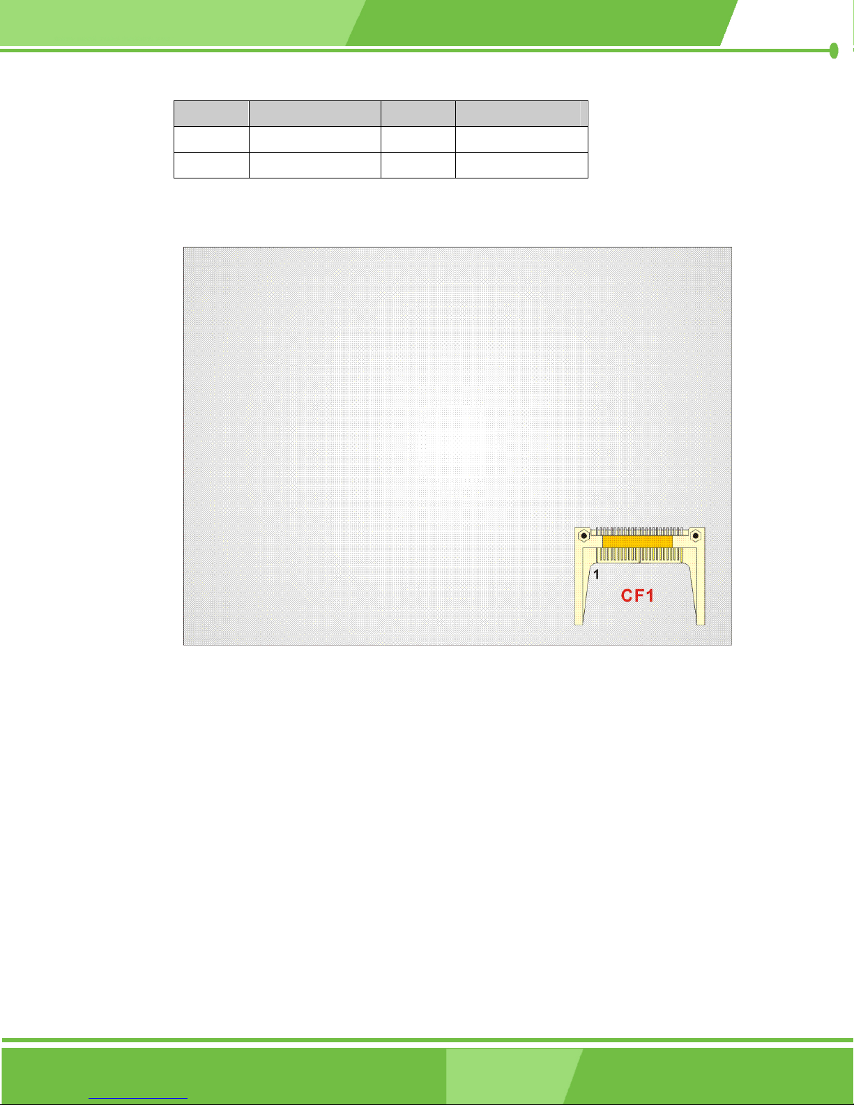
PIN NO. DESCRIPTION PIN NO. DESCRIPTION
24 N/C 49 DATA 10
25 VCC-IN CHECK2 50 GROUND
Table 3-10: CF1 Connector Pinouts
Figure 3-9: CF1 Connector Location
3.2.8 CPU Cooling Fan Connector
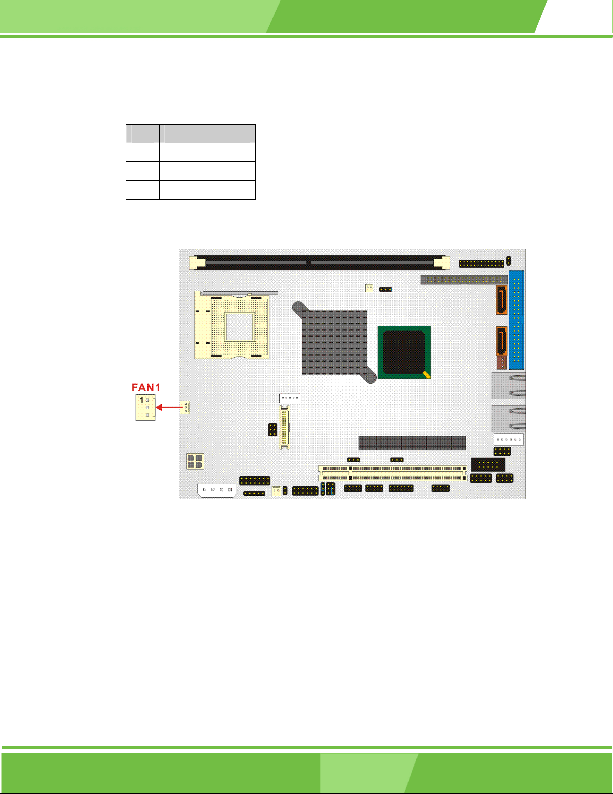
CN Label: FAN1
CN Type: 3-pin header
CN Location: See Figure 3-10
CN Pinouts: See Table 3-11
The FAN1 cooling fan connector provides a 12V, 350mA ~ 740mA or 1A ~ 2.2A current to
the cooling fan. The connector has a "rotation" pin to get rotation signals from the fan and
52
®
IEI
Technology, Corp.
Page 53
NOVA-8450 CPU Card
notify the system so the system BIOS can recognize the fan speed. Please note that only
certain fans can issue the rotation signals.
PIN DESCRIPTION
1 Fan Speed Detect
2 +12V
3 GND
Table 3-11 FAN1 Connector Pinouts
Figure 3-10 FAN1 Connector Location
3.2.9 External Power Connector
CN Label: PCN1
CN Type: 4-pin header
CN Location: See Figure 3-11
CN Pinouts: See Table 3-12
The External Power connector is a 12V/5V power in connector.
53
Page 54
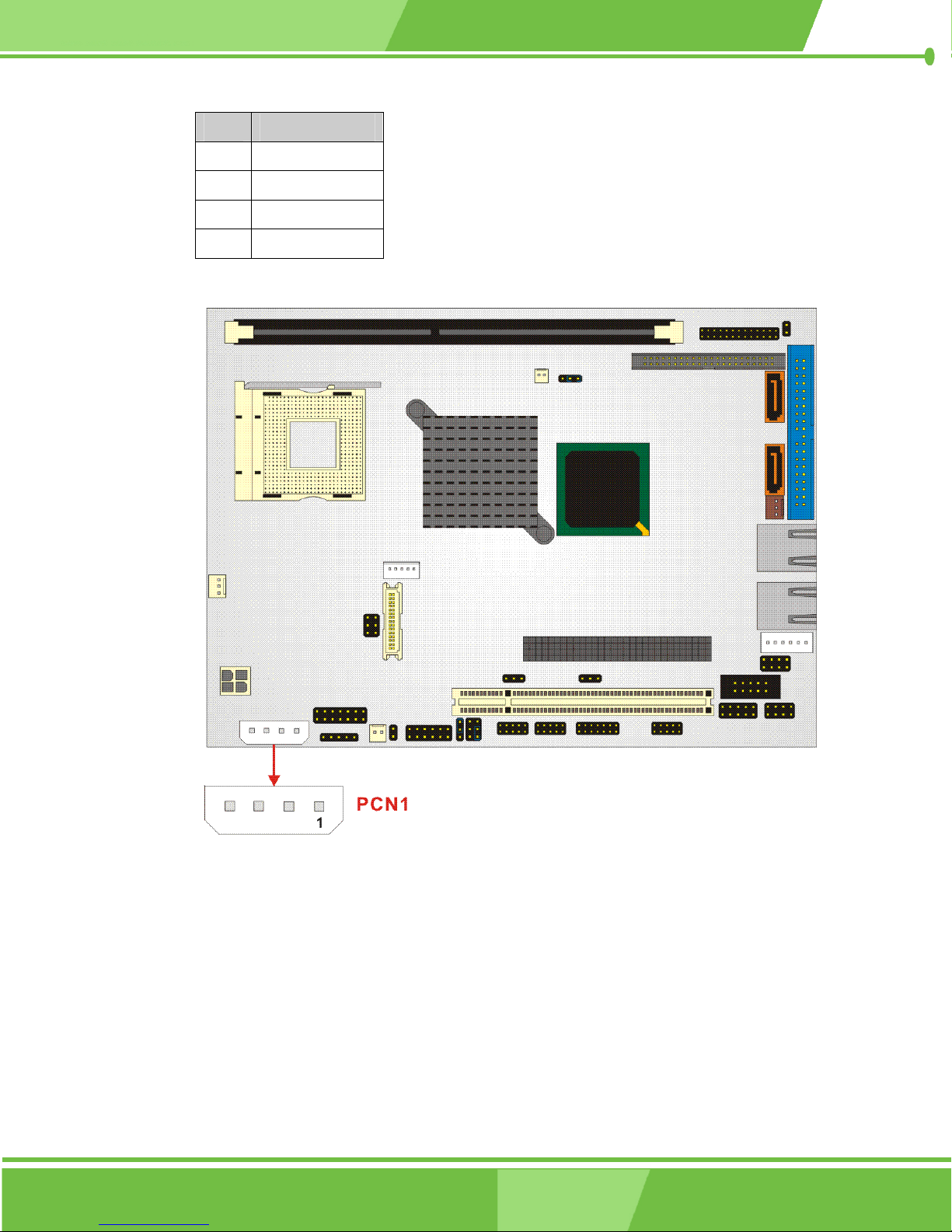
PIN DESCRIPTION
1 +5V
2 GND
3 GND
4 +12V
Table 3-12: PCN1 Connector Pinouts
Figure 3-11: PCN1 Connector Location
54
®
IEI
Technology, Corp.
Page 55
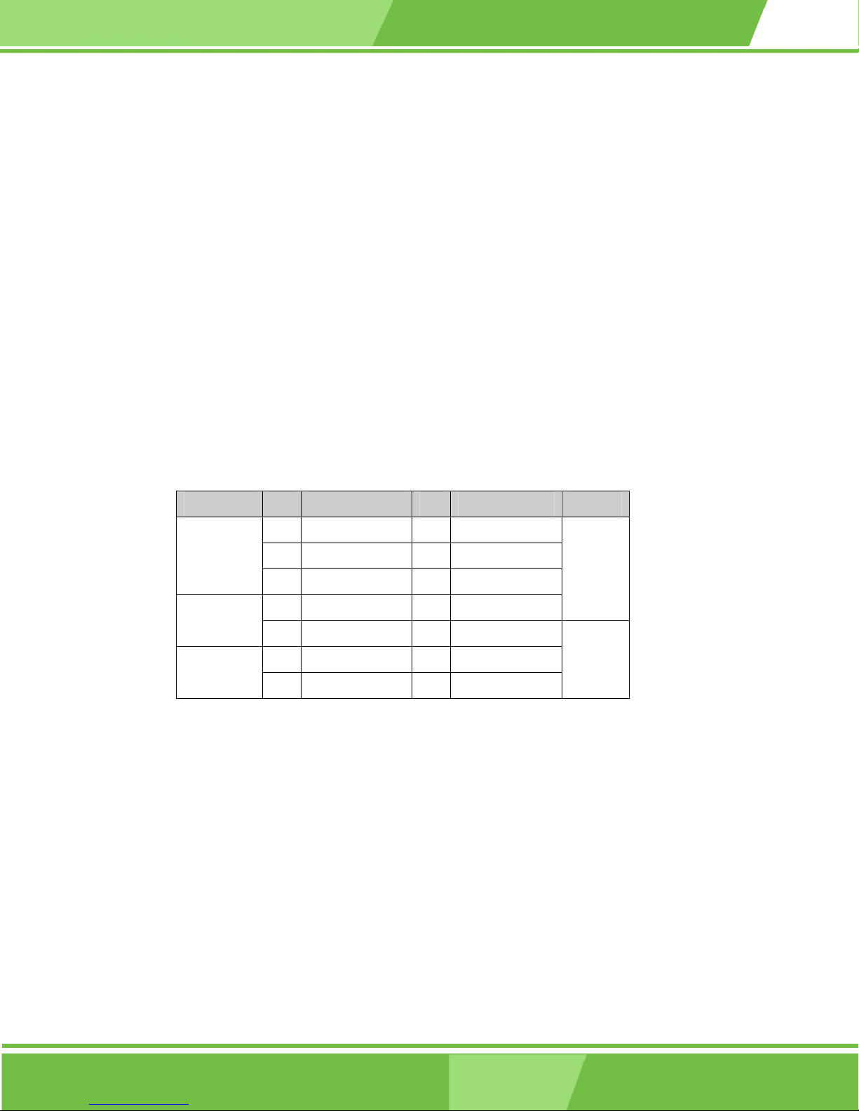
3.2.10 Front Panel Connector
CN Label: CN3
CN Type: 14-pin header (2x7 pins)
CN Location: See Figure 3-12
CN Pinouts: See Table 3-13
The front panel connector connects to:
the system chassis front panel LEDs
the chassis speaker
the power switch
NOVA-8450 CPU Card
the reset button.
ITEM PIN DESCRIPTION PIN DESCRIPTION ITEM
1 LED_POWER 2 +5V
Power LED
NC
HDDLED
Table 3-13: CN3 Connector Pinouts
3 N/C 4 N/C
5 Ground 6 N/C
7 NC 8 Speaker
9 Ground 10 Reset
11 Ground 12 Ground
13 HDLED 14 HDLED-
Speaker
RESET
55
Page 56
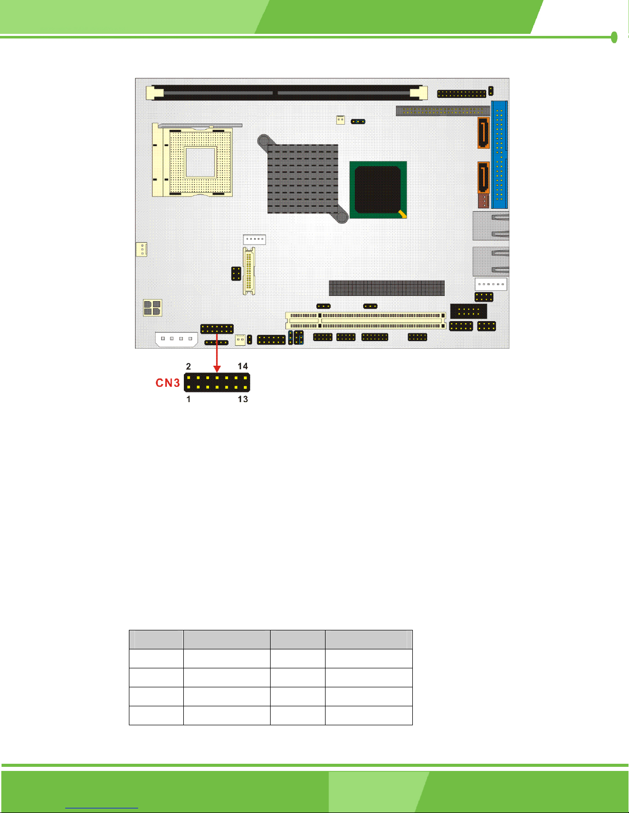
Figure 3-12: CN3 Connector Location
3.2.11 IDE Interface Connector (Primary)
CN Label: IDE1
CN Type: 40-pin header (2x20 pins)
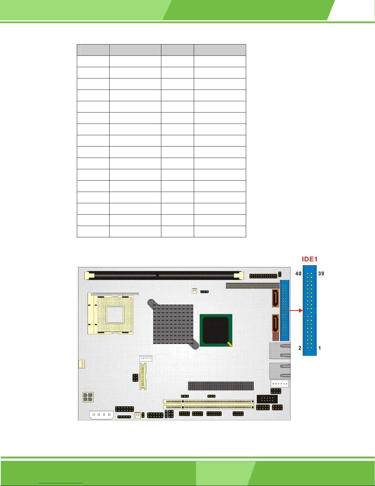
CN Location: See Figure 3-13
CN Pinouts: See Table 3-14
The IDE Interface connector provides connectivity for two IDE devices.
PIN NO. DESCRIPTION PIN NO. DESCRIPTION
1 RESET# 2 GND
3 DATA 7 4 DATA 8
5 DATA 6 6 DATA 9
7 DATA 5 8 DATA 10
56
®
IEI
Technology, Corp.
Page 57
NOVA-8450 CPU Card
PIN NO. DESCRIPTION PIN NO. DESCRIPTION
9 DATA 4 10 DATA 11
11 DATA 3 12 DATA 12
13 DATA 2 14 DATA 13
15 DATA 1 16 DATA 14
17 DATA 0 18 DATA 15
19 GND 20 (KEY)
21 IDE DRQ 22 GND
23 IOW# 24 GND
25 IOR# 26 GND
27 IDE CHRDY 28 GND
29 IDE DACK 30 GND
31 INTERRUPT 32 N/C
33 SA1 34 P66DET
35 SA0 36 SA2
37 HDC CS0# 38 HDC CS1#
39 HDD ACTIVE# 40 GND
Table 3-14: IDE1 Connector Pinouts
Figure 3-13: IDE1 Connector Location
57
Page 58
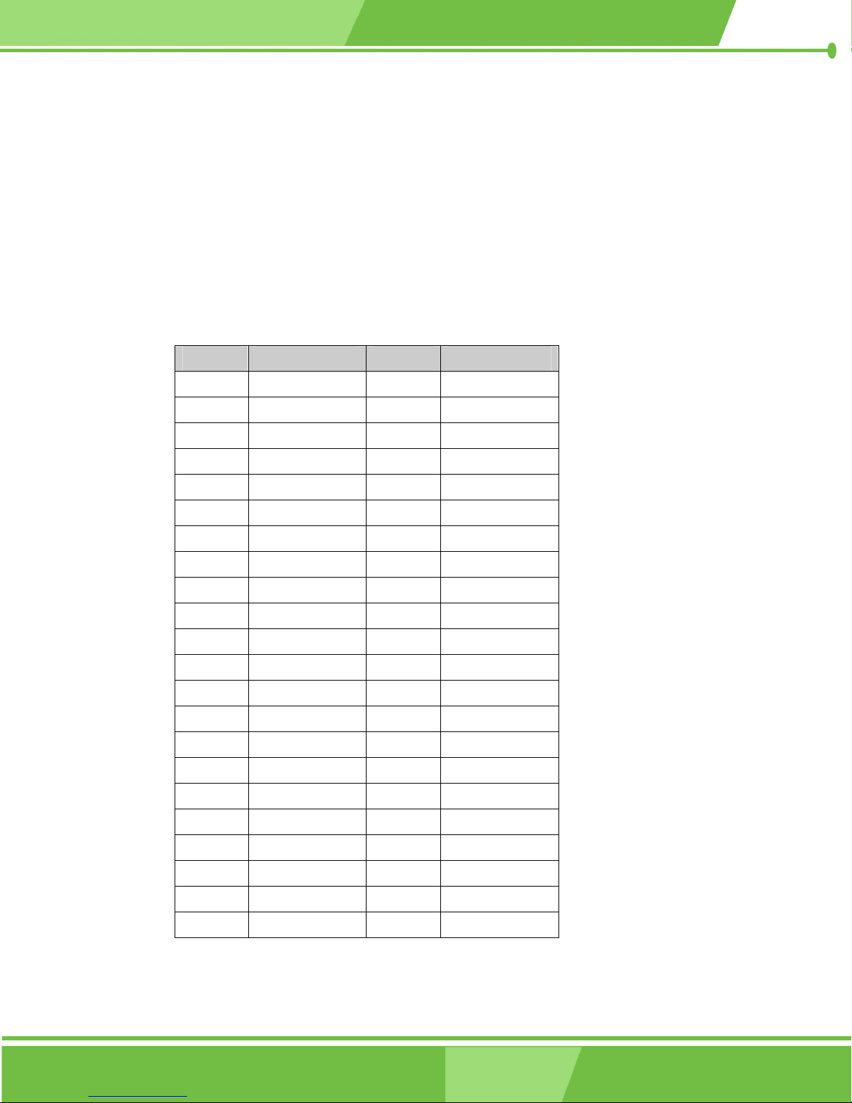
3.2.12 IDE Interface Connector (Secondary)
CN Label: IDE2
CN Type: 44-pin header (2x22 pins)
CN Location: See Figure 3-14
CN Pinouts: See Table 3-15
The IDE Interface connector provides connectivity for two IDE devices.
PIN NO. DESCRIPTION PIN NO. DESCRIPTION
1 RESET# 2 GND
3 DATA 7 4 DATA 8
5 DATA 6 6 DATA 9
7 DATA 5 8 DATA 10
9 DATA 4 10 DATA 11
11 DATA 3 12 DATA 12
13 DATA 2 14 DATA 13
15 DATA 1 16 DATA 14
17 DATA 0 18 DATA 15
19 SIGNAL GND 20 (KEY)
21 HDD 0 22 GND
23 IO WRITE 24 GND
25 IO READ 26 GND
27 HD READY 28 N/C
29 HDACK 0 30 GND
31 IRQ14 32 N/C
33 ADDR 1 34 N/C
35 ADDR 0 36 ADDR 2
37 HDD SELECT 0 38 HDD SELECT 1
39 IDE ACTIVE# 40 GND
41 VCC 42 VCC
43 GND 44 N/C
Table 3-15: IDE2 Connector Pinouts
58
IEI® Technology, Corp.
Page 59
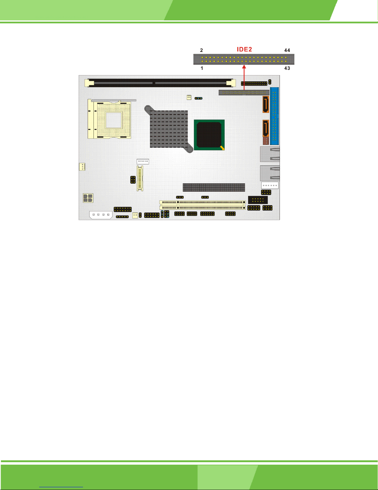
NOVA-8450 CPU Card
Figure 3-14: IDE2 Connector Location
59
Page 60
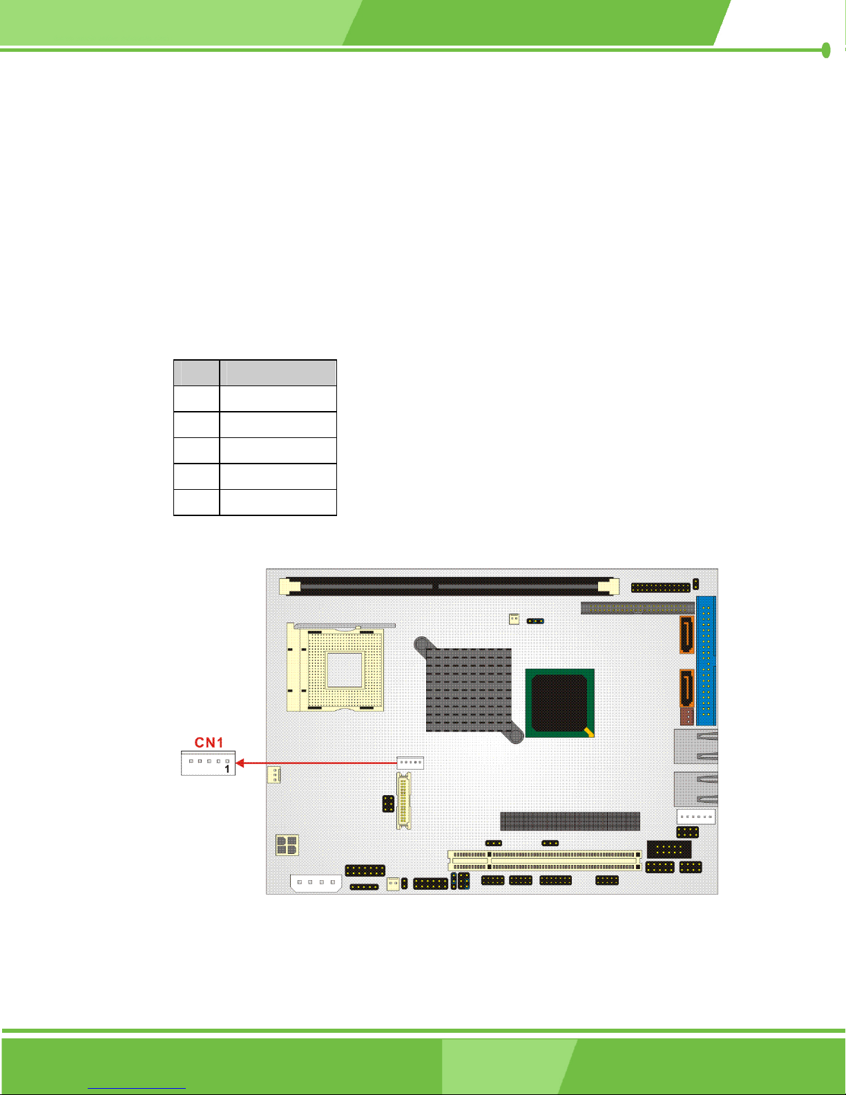
3.2.13 Inverter Connector
CN Label: CN1
CN Type: 5-pin header
CN Location: See Figure 3-15
CN Pinouts: See Table 3-16
The Inverter connector connects to the LCD backlight.
PIN DESCRIPTION
1 Brightness
2 GND
3 12V
4 GND
5 EN_BL
Table 3-16: CN1 Connector Pinouts
Figure 3-15: CN1 Connector Location
60
®
IEI
Technology, Corp.
Page 61
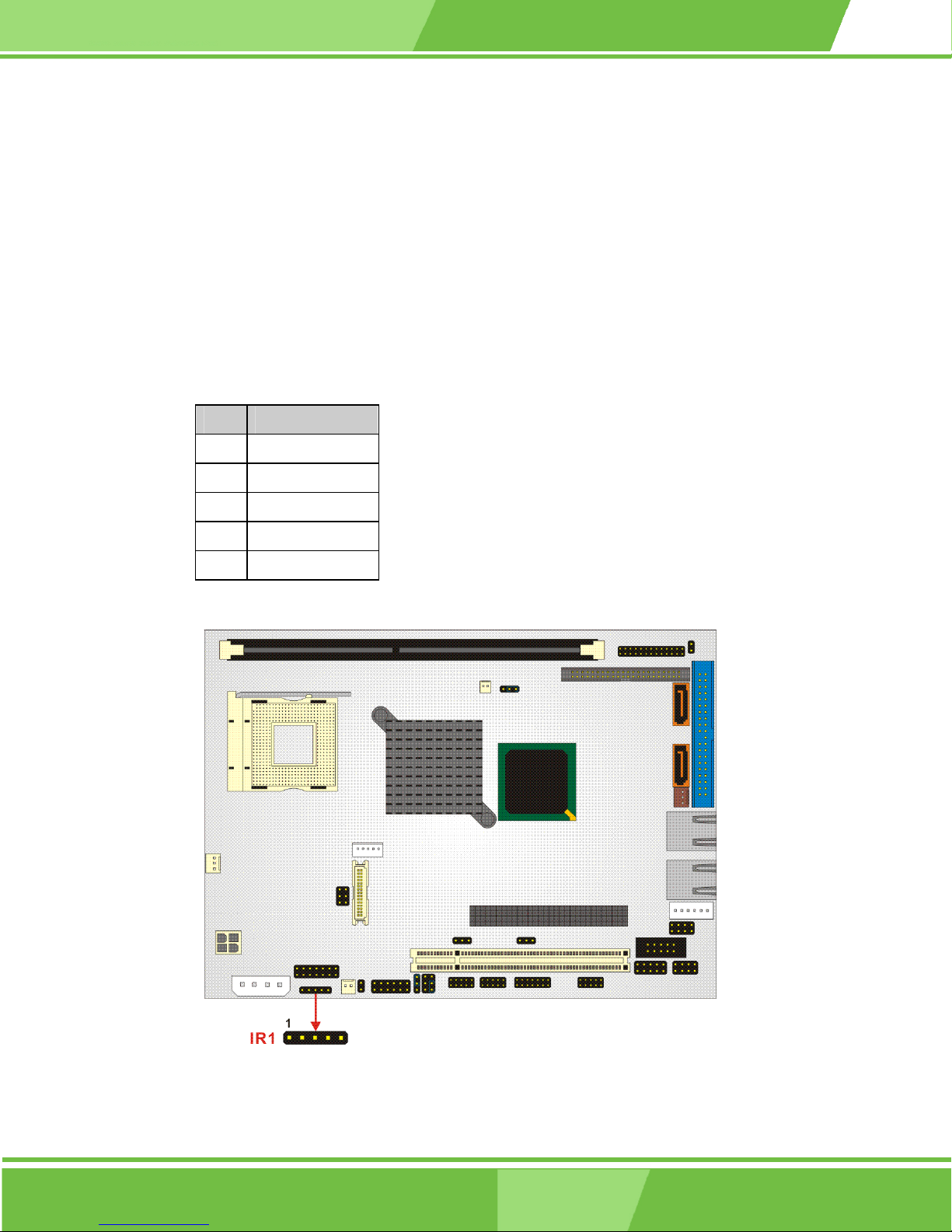
3.2.14 IrDA Connector
CN Label: IR1
CN Type: 5-pin header
CN Location: See Figure 3-16
CN Pinouts: See Table 3-17
The integrated IrDA connector supports both the SIR and ASKIR infrared protocols.
PIN DESCRIPTION
1 VCC5
2 NC
NOVA-8450 CPU Card
3 IR-RX
4 GND
5 IR-TX
Table 3-17: IR1 Connector Pinouts
Figure 3-16: IR1 Connector Location
61
Page 62
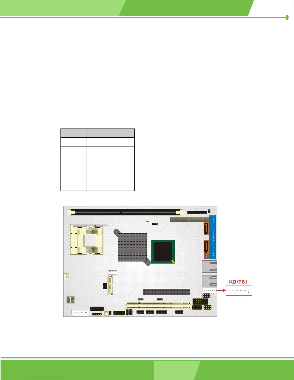
3.2.15 Keyboard/Mouse Connector
CN Label: KB/PS1
CN Type: 6-pin header
CN Location: See Figure 3-17
CN Pinouts: See Table 3-18
For alternative applications, an on board keyboard/mouse pin header connector is also
available.
PIN NO. DESCRIPTION
1 VCC5
2 MOUSE DATA
3 MOUSE CLK
4 KEYBOARD DATA
5 KEYBOARD CLK
6 GND
Table 3-18: KB/PS1 Connector Pinouts
Figure 3-17: KB/PS1 Connector Location
62
®
IEI
Technology, Corp.
Page 63
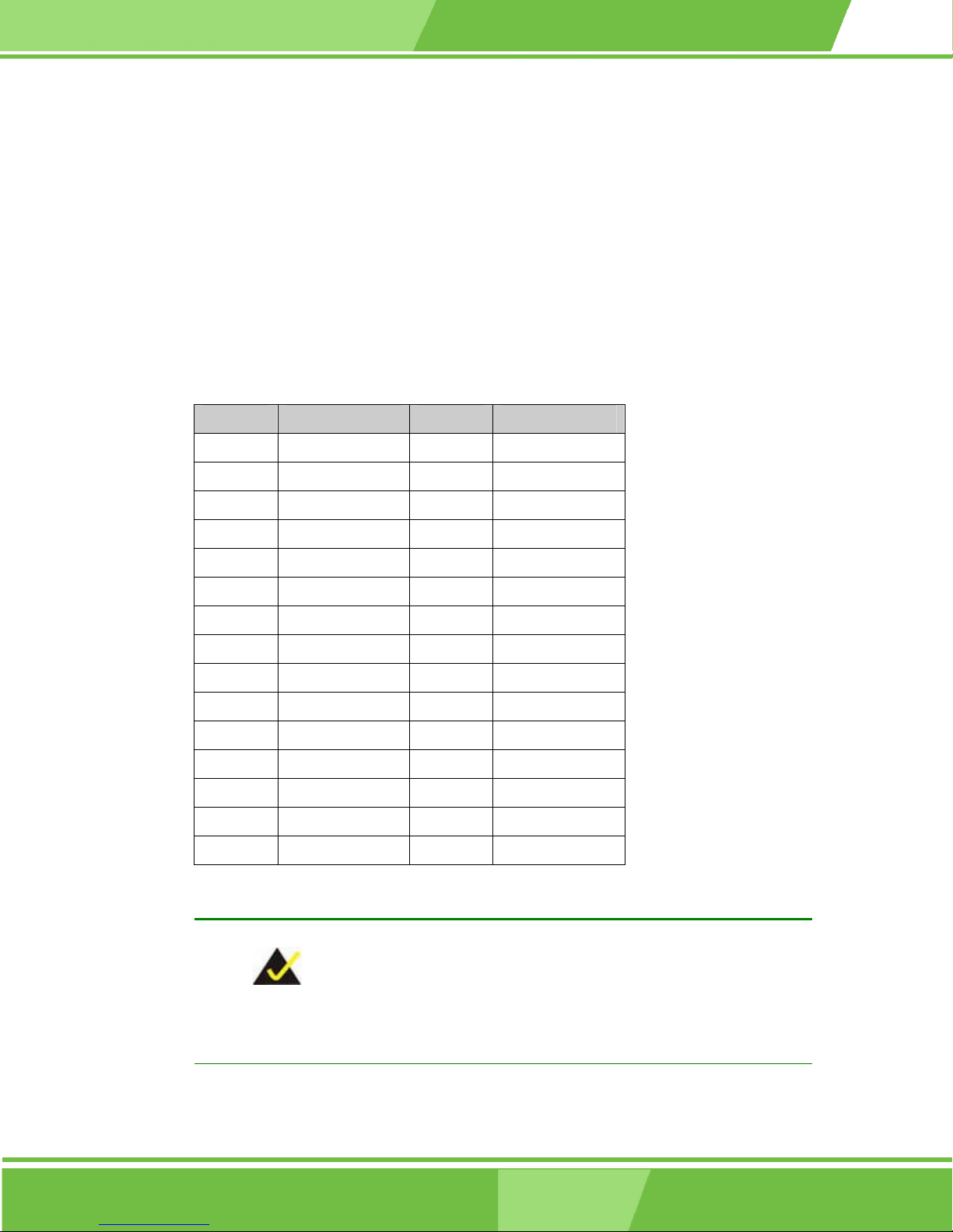
3.2.16 LVDS LCD Panel Connector
CN Label: LVDS1
CN Type: 30-pin header (2x15)
CN Location: See Figure 3-18
CN Pinouts: See Table 3-19
The LVDS LCD connector connects to a one or two channel (18-bit or 24-bit) LVDS panel.
PIN NO. DESCRIPTION PIN NO. DESCRIPTION
1 GND 2 GND
3 LVDS0+ 4 LVDS0-
NOVA-8450 CPU Card
5 LVDS1+ 6 LVDS1-
7 LVDS2+ 8 LVDS2-
9 LVDSCLK+ 10 LVDSCLK-
11 LVDS3+ 12 LVDS3-
13 GND 14 GND
15 LVDSB0+ 16 LVDSB0-
17 LVDSB1+ 18 LVDSB1-
16 LVDSB2+ 20 LVDSB2-
21 LVDSBCLK+ 22 LVDSBCLK-
23 LVDSB3+ 24 LVDSB3-
25 GND 26 GND
27 VCCLCD 28 VCCLCD
29 VCCLCD 30 VCCLCD
Table 3-19: LVDS1 Connector Pinouts
NOTE:
The supplied voltage can be selected via JP7.
63
Page 64
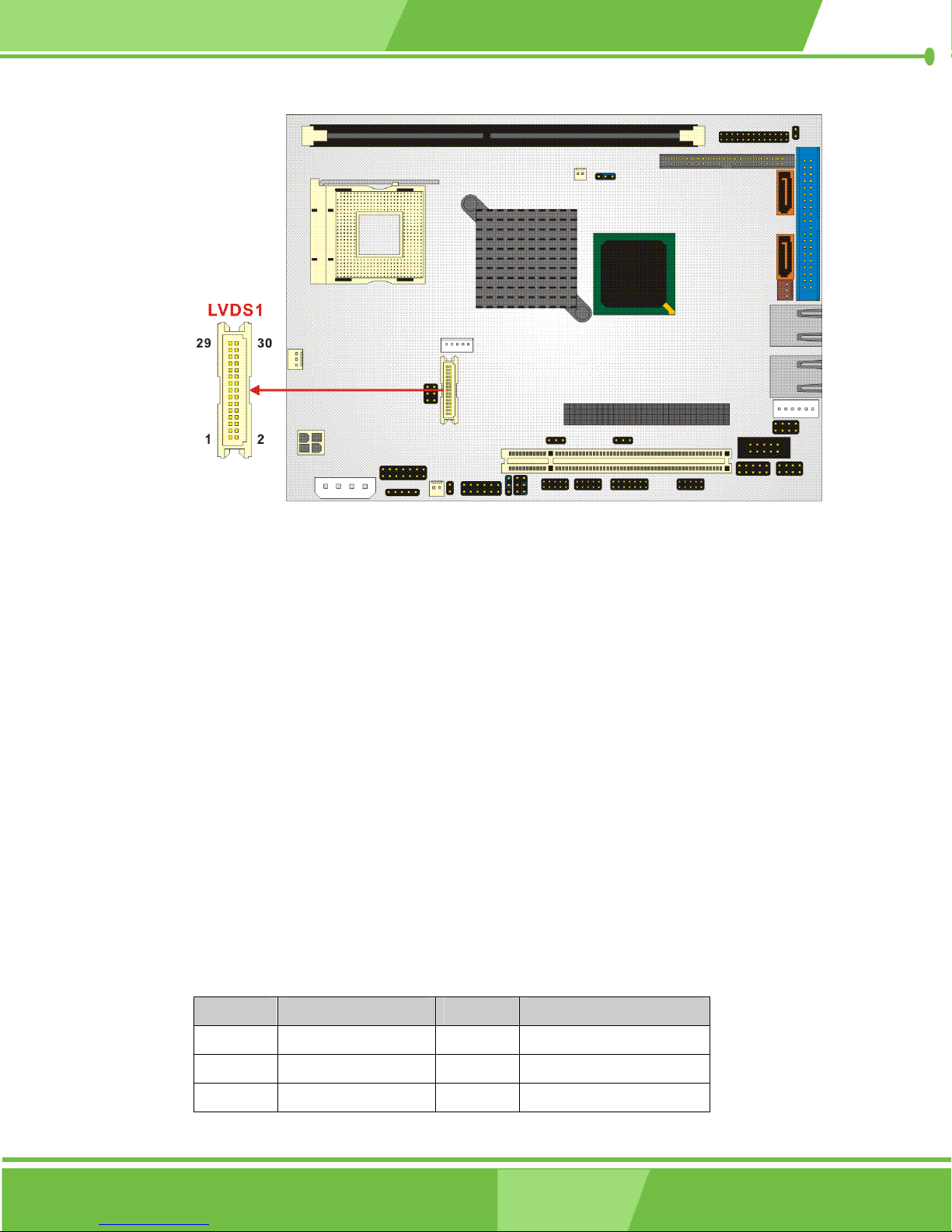
Figure 3-18: LVDS1 Connector Location
3.2.17 Parallel Port Connector
CN Label: LPT1
CN Type: 26-pin header (2x13 pins)
CN Location: See Figure 3-19
CN Pinouts: See Table 3-20
The parallel port connector connects to a printer. The NOVA-8450 comes with a
multi-mode (ECP/EPP/SPP) parallel port. The LPT1 parallel port interface features a
26-pin flat-cable connector that requires an adapter cable if a traditional DB-25 connector is
preferred. The parallel interface can be re-assigned to LPT2 or LPT3 through the BIOS
configuration utility. The default interrupt channel is IRQ7. Select ECP or EPP DMA mode
using the BIOS configuration utility.
PIN NO. DESCRIPTION PIN NO. DESCRIPTION
1 STROBE# 14 AUTO FORM FEED #
2 DATA 0 15 ERROR#
3 DATA 1 16 INITIALIZE
64
®
IEI
Technology, Corp.
Page 65
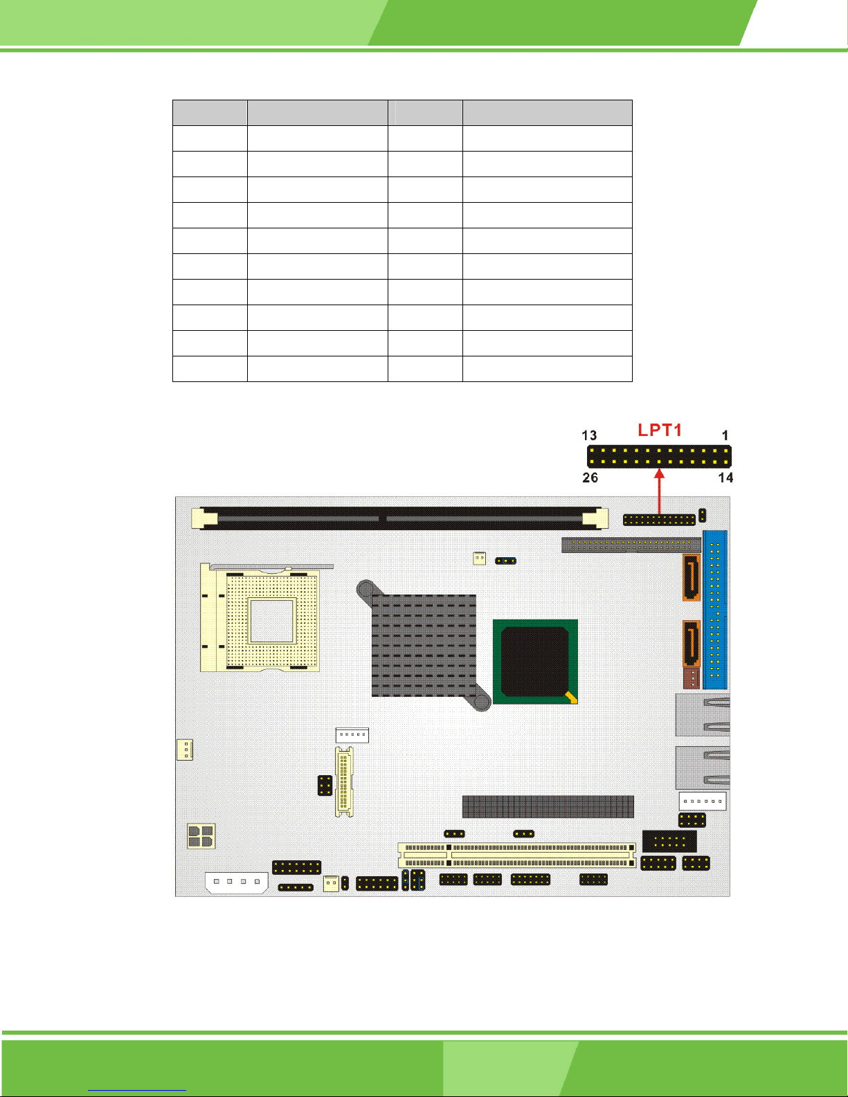
NOVA-8450 CPU Card
PIN NO. DESCRIPTION PIN NO. DESCRIPTION
4 DATA 2 17 PRINTER SELECT LN#
5 DATA 3 18 GROUND
6 DATA 4 19 GROUND
7 DATA 5 20 GROUND
8 DATA 6 21 GROUND
9 DATA 7 22 GROUND
10 ACKNOWLEDGE 23 GROUND
11 BUSY 24 GROUND
12 PAPER EMPTY 25 GROUND
13 PRINTER SELECT 26 GROUND
Table 3-20: LPT1 Connector Pinouts
Figure 3-19: LPT1 Connector Location
65
Page 66
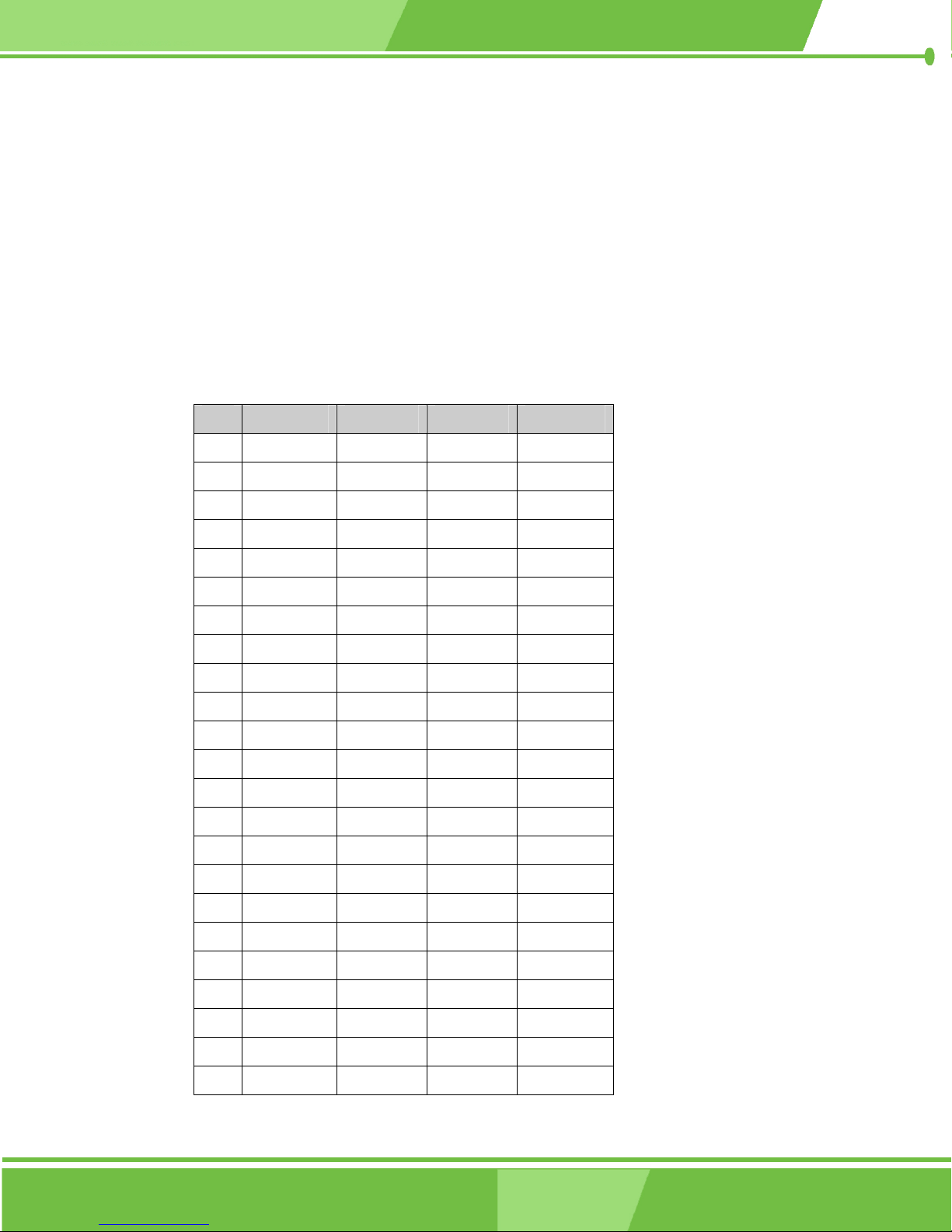
3.2.18 PCI-104 Connector
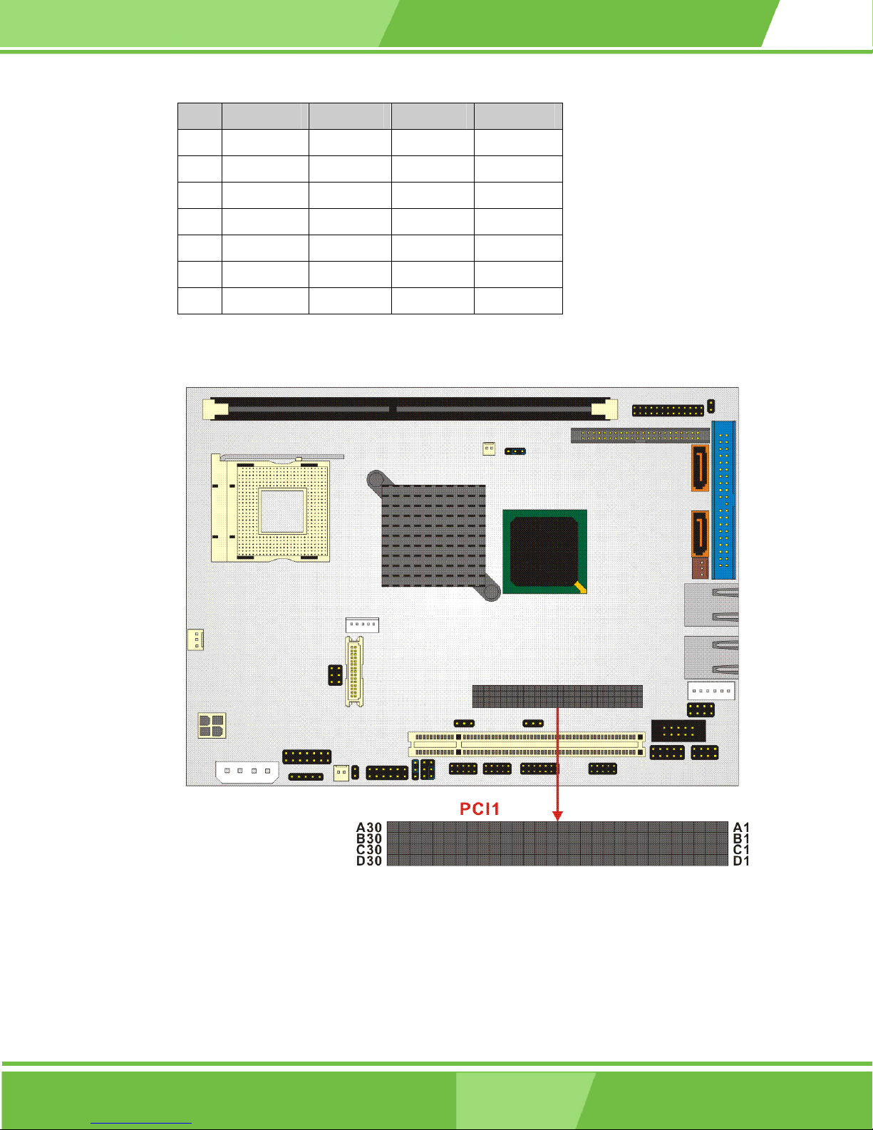
CN Label: PCI1
CN Type: PCI-104 Module
CN Location: See Figure 3-20
CN Pinouts: See Table 3-21
Use the PCI-104 connector to add auxiliary boards using stack-through connectors.
Pin A B C D
1 GND Reserved 5 AD00
2 VI/O AD02 AD01 +5V
3 AD05 GND AD04 AD03
4 C/BE0# AD07 GND AD06
5 GND AD09 AD08 GND
6 AD11 VI/O AD10 M66EN
7 AD14 AD13 GND AD12
8 +3.3V C/BE1# AD15 +3.3V
9 SERR# GND Reserved PAR
10 GND PERR# +3.3V Reserved
11 STOP# +3.3V LOCK# GND
12 +3.3V TRDY# GND DEVSEL#
13 FRAME# GND IRDY# +3.3V
14 GND AD16 +3.3V C/BE2#
15 AD18 +3.3V AD17 GND
16 AD21 AD20 GND AD19
17 +3.3V AD23 AD22 +3.3V
18 IDSEL0 GND IDSEL1 IDSEL2
19 AD24 C/BE3# VI/O IDSEL3
20 GND AD26 AD25 GND
21 AD29 +5V AD28 AD27
22 +5V AD30 GND AD31
23 REQ0# GND REQ1# VI/O
66
IEI® Technology, Corp.
Page 67
NOVA-8450 CPU Card
Pin A B C
24 GND REQ2# D +5V GNT0#
25 GNT1# VI/O GNT2# GND
26 +5V CLK0 GND CLK1
27 CLK2 +5V CLK3 GND
28 GND INTD# +5V RST#
29 +12V INTA# INTB# INTC#
30 REQ3# GNT3# GND
Table 3-21: PCI1 Connector Pinouts
-12V
Figure 3-20: PCI1 Connector Location
67
Page 68
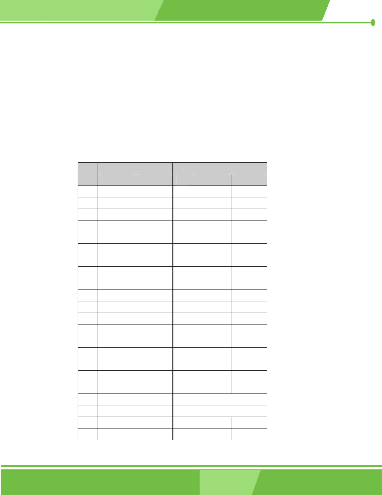
3.2.19 PCI2 Connector
CN Label: PCI2
CN Type: PCI Slot
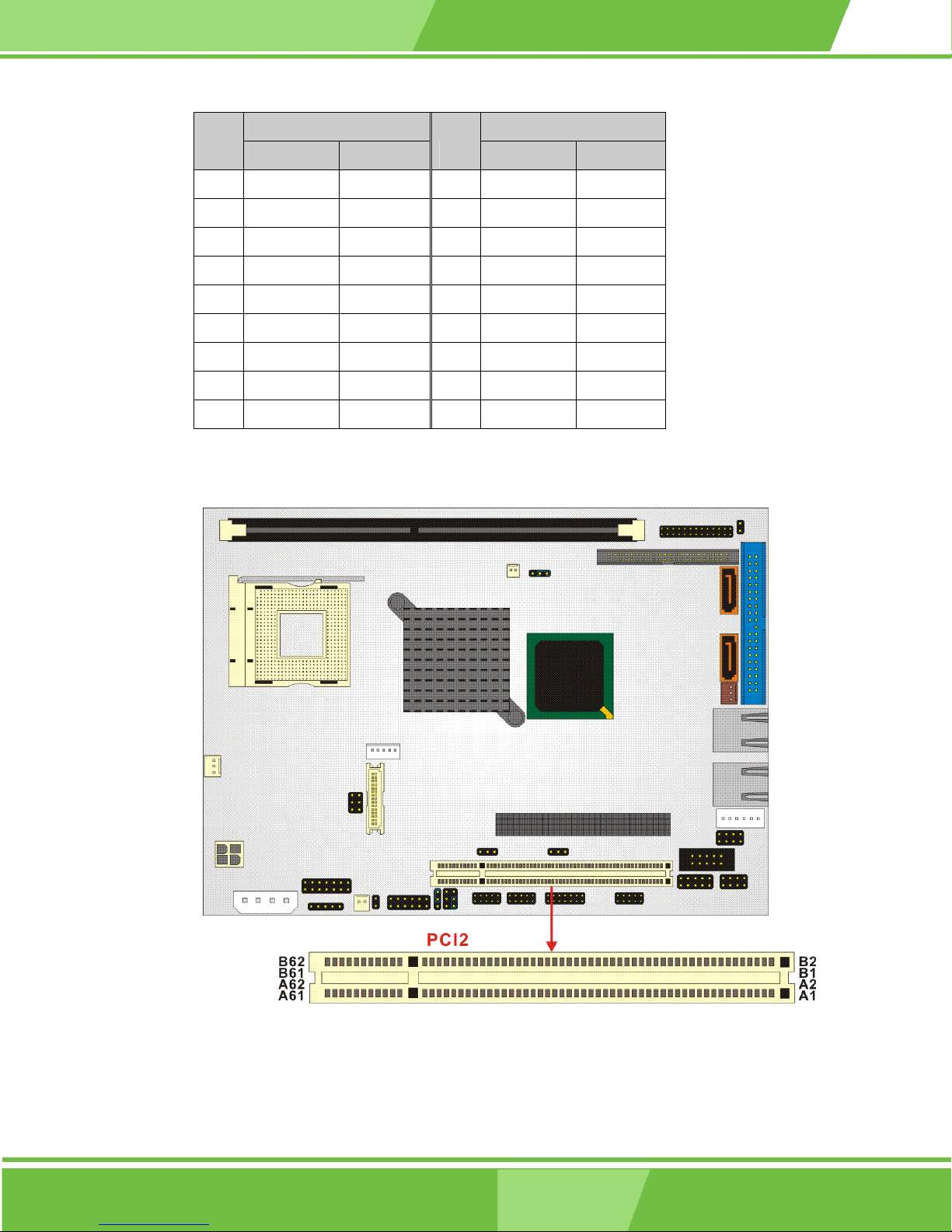
CN Location: See Figure 3-21
CN Pinouts: See Table 3-22
Use the PCI slot connector to add auxiliary boards.
Add-in Card Add-in Card
Pin
1 Reserved Ground 32 AD[17] AD[16]
2 TCK +12V 33 C/BE[2]# +3.3V
3 Ground TMS 34 Ground FRAME#
4 TDO TDI 35 IRDY# Ground
5 +5V +5V 36 +3.3V TRDY#
6 +5V INTA# 37 DEVSEL# Ground
7 INTB# INTC# 38 PCIXCAP STOP#
8 INTD# +5V 39 LOCK# +3.3V
9 PRSNT1# Reserved 40 PERR# SMBCLK
10 Reserved +5V 41 +3.3V SMBDAT
11 PRSNT2# Reserved 42 SERR# Ground
12 Ground Ground 43 +3.3V PAR
13 Ground Ground 44 C/BE[1]# AD[15]
14 Reserved 3.3Vaux 45 AD[14] +3.3V
15 Ground RST# 46 Ground AD[13]
Side B Side A
Pin
Side B Side A
16 CLK +5V 47 AD[12] AD[11]
17 Ground GNT# 48 AD[10] Ground
18 REQ# Ground 49 M66EN AD[09]
19 +5V PME# 50 KEYWAY
20 AD[31] AD[30] 51 KEYWAY
21 AD[29] +3.3V 52 AD[08] C/BE[0]#
22 Ground AD[28] 53 AD[07] +3.3V
68
IEI® Technology, Corp.
Page 69
NOVA-8450 CPU Card
Add-in Card Add-in Card
Pin
23 AD[27] AD[26] 54 +3.3V AD[06]
24 AD[25] Ground 55 AD[05] AD[04]
25 +3.3V AD[24] 56 AD[03] Ground
26 C/BE[3]# IDSEL 57 Ground AD[02]
27 AD[23] +3.3V 58 AD[01] AD[00]
28 Ground AD[22] 59 +5V +5V
29 AD[21] AD[20] 60 ACK64# REQ64#
30 AD[19] Ground 61 +5V +5V
31 +3.3V AD[18] 62 +5V +5V
Table 3-22: PCI2 Connector Pinouts
Side B Side A
Pin
Side B Side A
Figure 3-21: PCI2 Connector Location
69
Page 70
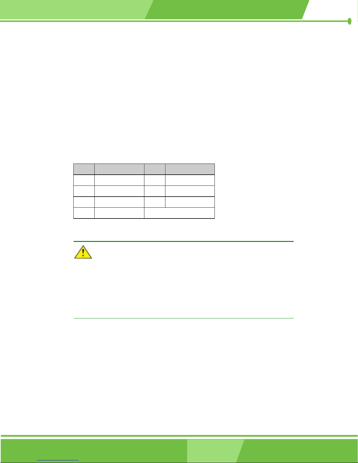
3.2.20 SATA Drive Ports
CN Label: SATA1, SATA2
CN Type: 7-pin port
CN Location: See Figure 3-22
CN Pinouts: See Table 3-23
The SATA drive ports provide connectivity to SATA drives with a maximum data transfer
rate of 150Mb/s.
PIN DESCRIPTION PIN DESCRIPTION
1 GND 5 RX-
2 TX+ 6 RX+
3 TX- 7 GND
4 GND
Table 3-23: SATA1, SATA2 Connector Pinouts
CAUTION!
SATA hard drives may come with both a 4P power connector and a SATA
power interface. Attach either the 4P connector or the SATA power cable to
the SATA hard drives.
SATA hard drives at the same time! Doing so will cause damage.
DO NOT attach both the power connectors to your
70
®
IEI
Technology, Corp.
Page 71
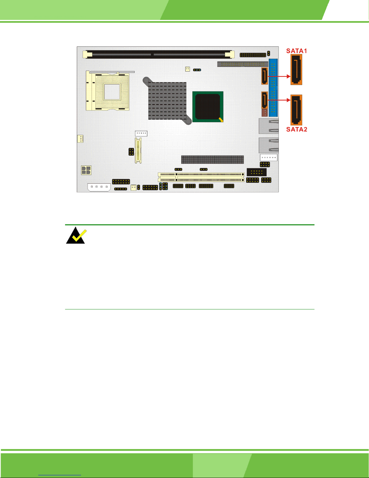
NOVA-8450 CPU Card
Figure 3-22: SATA1, SATA2 Connector Locations
NOTE:
1. SATA is supported by:
• Windows 2000 SP4
• Windows XP SP1
• Windows 2003, or later versions.
3.2.21 RS-232 Serial Communications Connector
2. Older OSes, such as Windows 98SE or ME, do not support the SATA interface.
CN Label: COM1, COM3, COM4
CN Type: 10-pin headers (2x5 pins)
CN Location: See Figure 3-23
CN Pinouts: See Table 3-24
The NOVA-8450 offers three ten-pin headers for serial connections.
71
Page 72
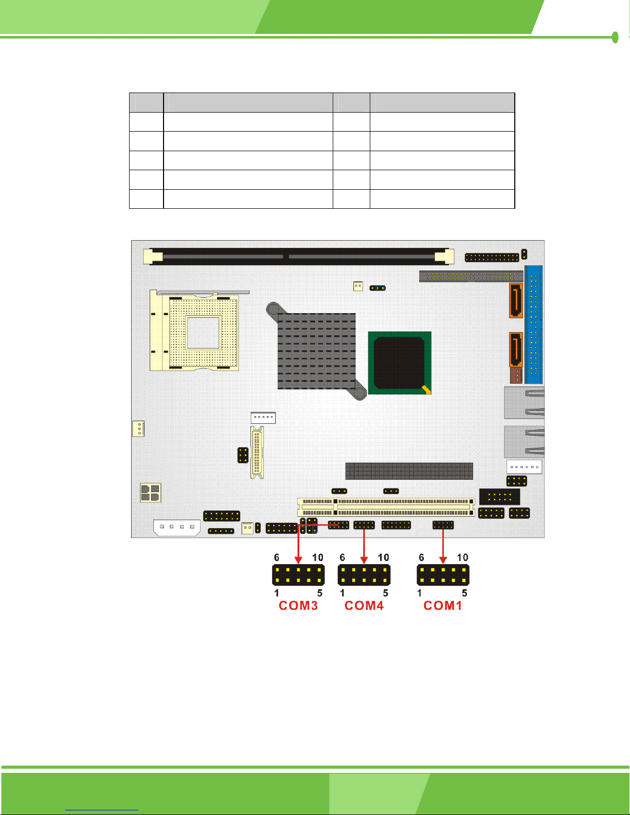
PIN DESCRIPTION PIN DESCRIPTION
1 DATA CARRIER DETECT (DCD) 6 DATA SET READY (DSR)
2 RECEIVE DATA (RXD) 7 REQUEST TO SEND (RTS)
3 TRANSMIT DATA (TXD) 8 CLEAR TO SEND (CTS)
4 DATA TERMINAL READY (DTR) 9 RING INDICATOR (RI)
5 GND (GND) 10 GND (GND)
Table 3-24: COM1, COM3, COM4 Connector Pinouts
Figure 3-23 COM1, COM3, COM4 Connector Location
72
®
IEI
Technology, Corp.
Page 73
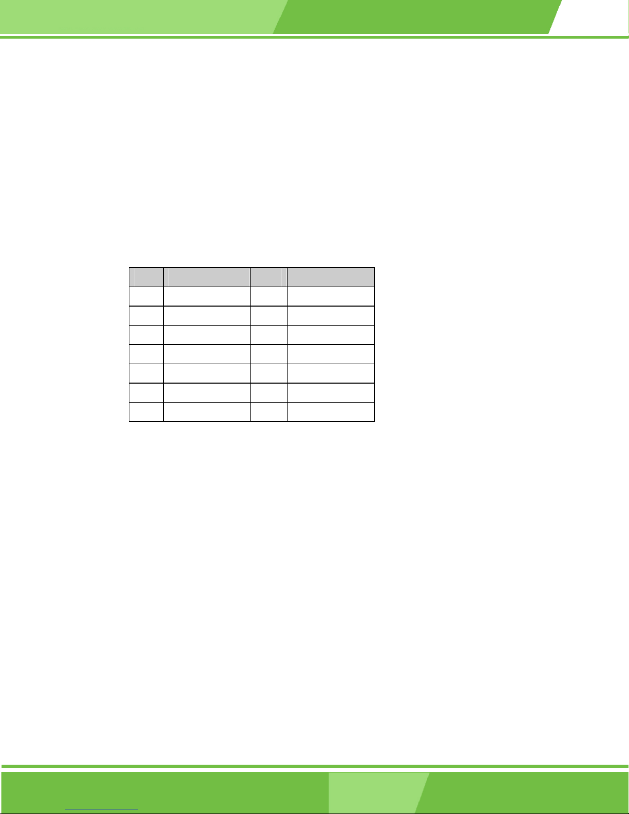
3.2.22 RS-232/422/485 Serial Communications Connector
CN Label: COM2
CN Type: 14-pin header (2x7 pins)
CN Location: See Figure 3-24
CN Pinouts: See Table 3-25
The NOVA-8450 offers one 14-pin header for serial connections.
PIN DESCRIPTION PIN DESCRIPTION
1 NDCD2 8 NDSR2
2 NRX2 9 NRTS2
NOVA-8450 CPU Card
3 NTX2 10 NCTS2
4 NDTR2 11 NRI2
5 GND 12 GND
6 TX2+ 13 TX2-
7 RX2+ 14 RX2-
Table 3-25: COM2 Connector Pinouts
73
Page 74
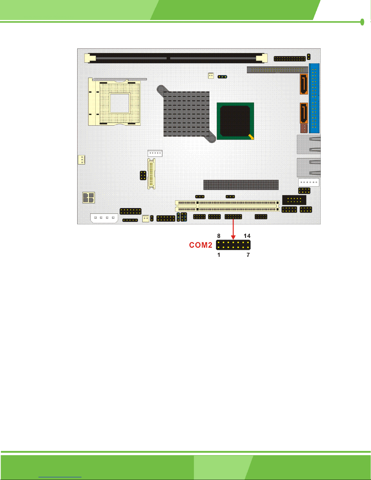
Figure 3-24 COM2 Connector Location
3.2.23 Internal USB Connectors
CN Label: USB1, USB2
CN Type: 8-pin header (2x4 pins)
CN Location: See Figure 3-25
CN Pinouts: See Table 3-26
Two 2x4 pin connectors provide connectivity to four USB 2.0 ports. The USB ports are
used for I/O bus expansion.
74
®
IEI
Technology, Corp.
Page 75
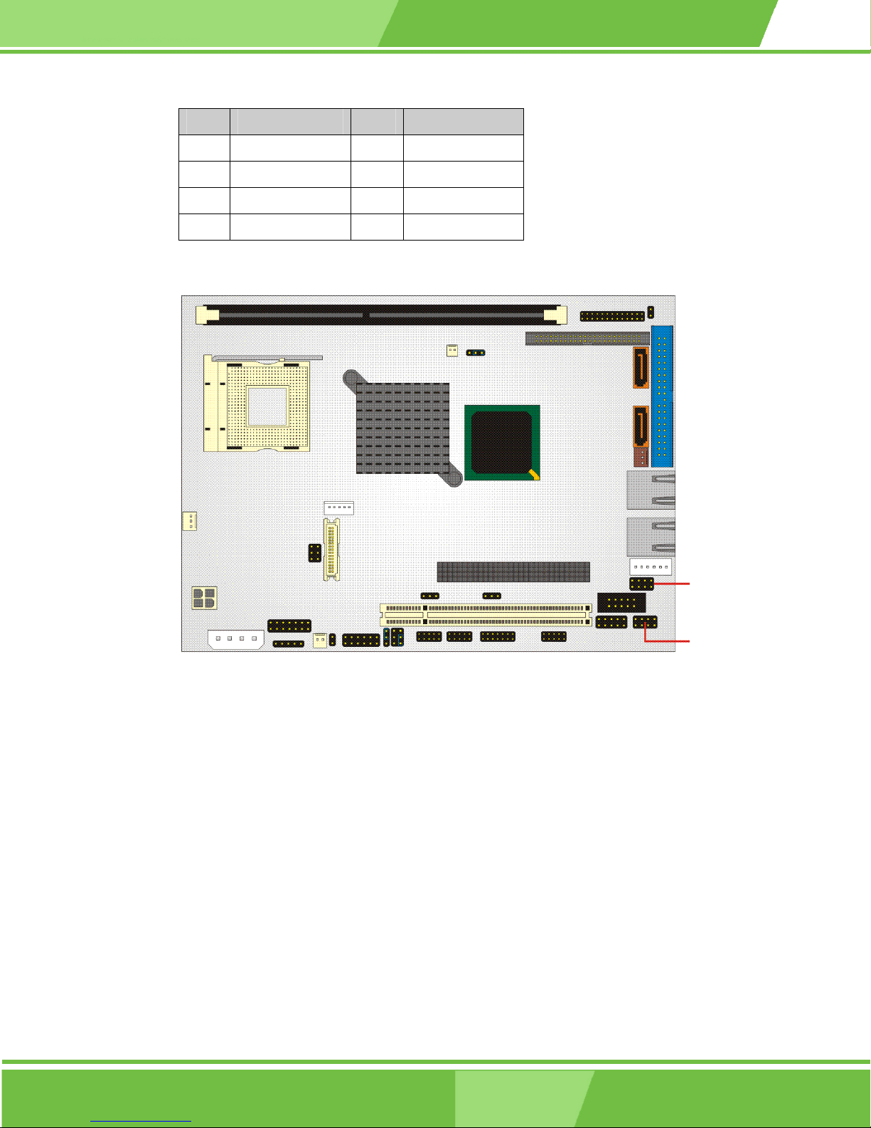
NOVA-8450 CPU Card
PIN DESCRIPTION PIN DESCRIPTION
1 USBV0L 2 GND
3 DATA0_N 4 DATA1_P
5 DATA0_P 6 DATA1_N
7 GND 8 USBV0L
Table 3-26: USB1, USB2 Connector Pinouts
Figure 3-25: USB1, USB2 Connector Locations
3.2.24 VGA Connector
CN Label: VGA1
CN Type: 10-pin headers (2x5 pins)
CN Location: See Figure 3-26
CN Pinouts: See Table 3-27
The VGA1 connector is an internal VGA connector.
75
Page 76
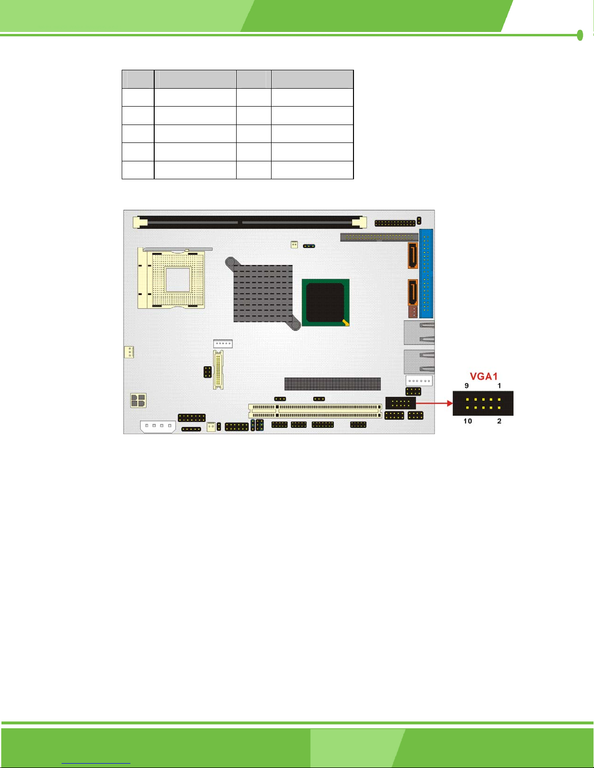
PIN DESCRIPTION PIN DESCRIPTION
1 RED 2 DDCCLK
3 GREEN 4 DDCDAT
5 BLUE 6 GROUND
7 HSYNC 8 GROUND
9 VSYNC 10 GROUND
Table 3-27: VGA1 Connector Pinouts
Figure 3-26 VGA1 Connector Location
76
®
IEI
Technology, Corp.
Page 77
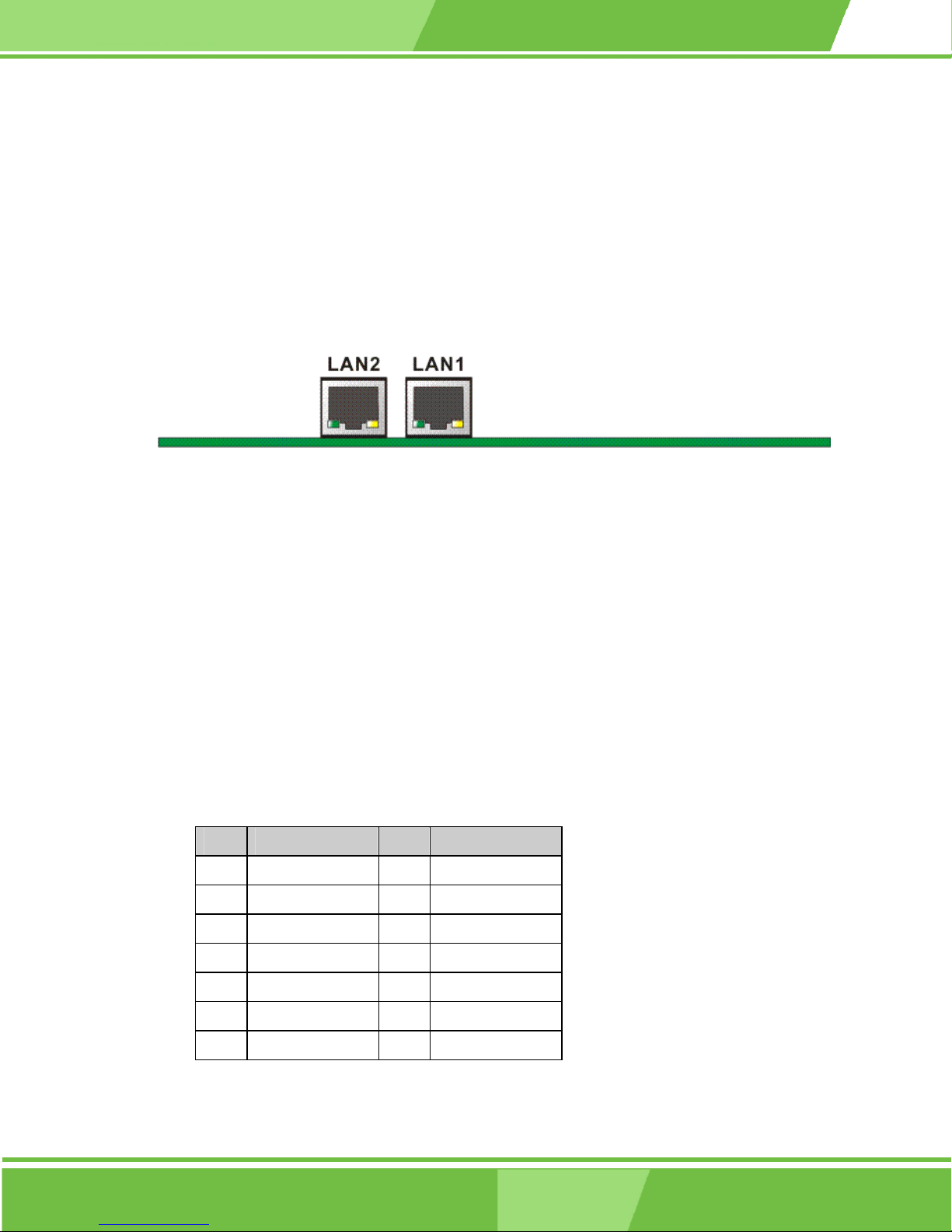
3.3 External (Rear Panel) Connectors
Figure 3-27 shows the NOVA-8450 CPU card rear panel. The peripheral connectors on
the back panel can connect to external devices when the CPU card is installed in a chassis.
The peripheral connectors on the rear panel are:
2 x RJ-45 Ethernet connectors
Figure 3-27: NOVA-8450 CPU Board Rear Panel
NOVA-8450 CPU Card
3.3.1 Ethernet Connector
CN Label: LAN1, LAN2
CN Type: RJ-45
CN Location: See Figure 3-27
CN Pinouts: See Table 3-28
A 1Gb connection can be made between the Ethernet connector (Figure 3-28) and a Local
Area Network (LAN) through a network hub.
PIN DESCRIPTION PIN DESCRIPTION
1 TX0+ 2 TX0-
3 TX1+ 4 TX1-
5 V_DAC 6 V_DAC
7 TX2+ 8 TX3-
9 TX3+ 10 TX3-
11 LINK100- 12 LINK1000-
13 ACT- 14 ACT+
Table 3-28: LAN1, LAN2 Connector Pinouts
77
Page 78
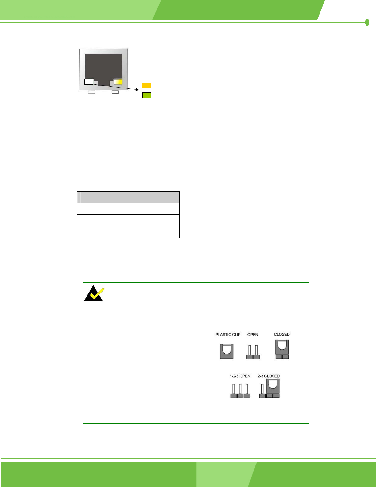
Giga LAN
10/100 LAN
Link
LED
ACT
LED
Figure 3-28: LAN1, LAN2 Connector
The RJ-45 Ethernet connector has two status LEDs, one green and one yellow. The green
LED indicates activity on the port and the yellow LED indicates the port is linked (Table
3-29).
STATUS DESCRIPTION
ORANGE 1000M is linked
GREEN 100M is linked
YELLOW Activity
Table 3-29: RJ-45 Ethernet Connector LEDs
3.4 Onboard Jumpers
NOTE:
A jumper is a metal bridge used to close
an electrical circuit. It consists of two or
three metal pins and a small metal clip
(often protected by a plastic cover) that
slides over the pins to connect them. To
CLOSE/SHORT a jumper means
connecting the pins of the jumper with
the plastic clip and to OPEN a jumper
means removing the plastic clip from a
jumper.
Figure 3-29: Jumper Locations
The NOVA-8450 CPU Board has seven onboard jumpers (Figure 3-30).
78
®
IEI
Technology, Corp.
Page 79
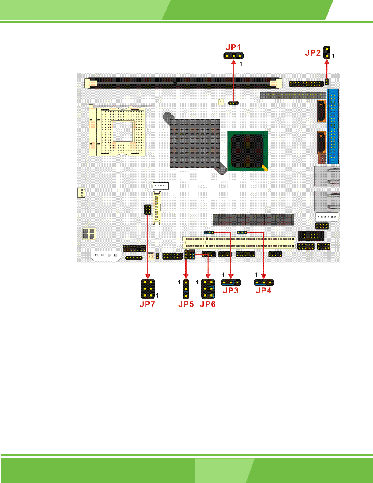
NOVA-8450 CPU Card
Figure 3-30: Jumper Locations
3.4.1 Clear CMOS Setup Jumper
Jumper Label: JP1
Jumper Type: 3-pin header
Jumper Settings: See Table 3-30
Jumper Location: See Figure 3-29
79
Page 80
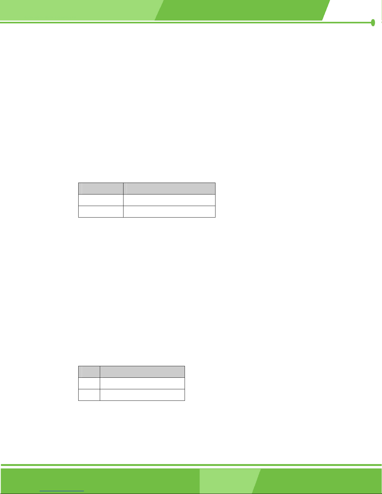
If the CPU card fails to boot due to improper BIOS settings, use this jumper to clear the
CMOS data and reset the system BIOS information. To do this, use the jumper cap to close
pins 2 and 3 for a few seconds then reinstall the jumper clip back to pins 1 and 2.
If the CMOS Settings Wrong message displays during the boot up process, press F1 to
enter the CMOS Setup menu, then do one of the following:
Enter the correct CMOS setting
Load Optimal Defaults
Load Failsafe Defaults.
Save the changes and exit the CMOS Setup menu.
JP1 CLEAR CMOS
1-2 closed Normal (default)
2-3 closed Clear CMOS
Table 3-30: Reset CMOS Jumper Settings
3.4.2 COM2 RS-232/422/485 Setup Jumper
Jumper Label: JP4
Jumper Type: 3-pin header
Jumper Settings: See Table 3-31
Jumper Location: See Figure 3-29
The JP4 jumper, when used in association with jumper JP5, sets the COM2 connector type
to RS-232 or RS-422/485.
JP4 Description
1-2 COM2 set to RS-232
2-3 COM2 set to RS-422/485
Table 3-31: JP4 Jumper Settings
80
IEI® Technology, Corp.
Page 81
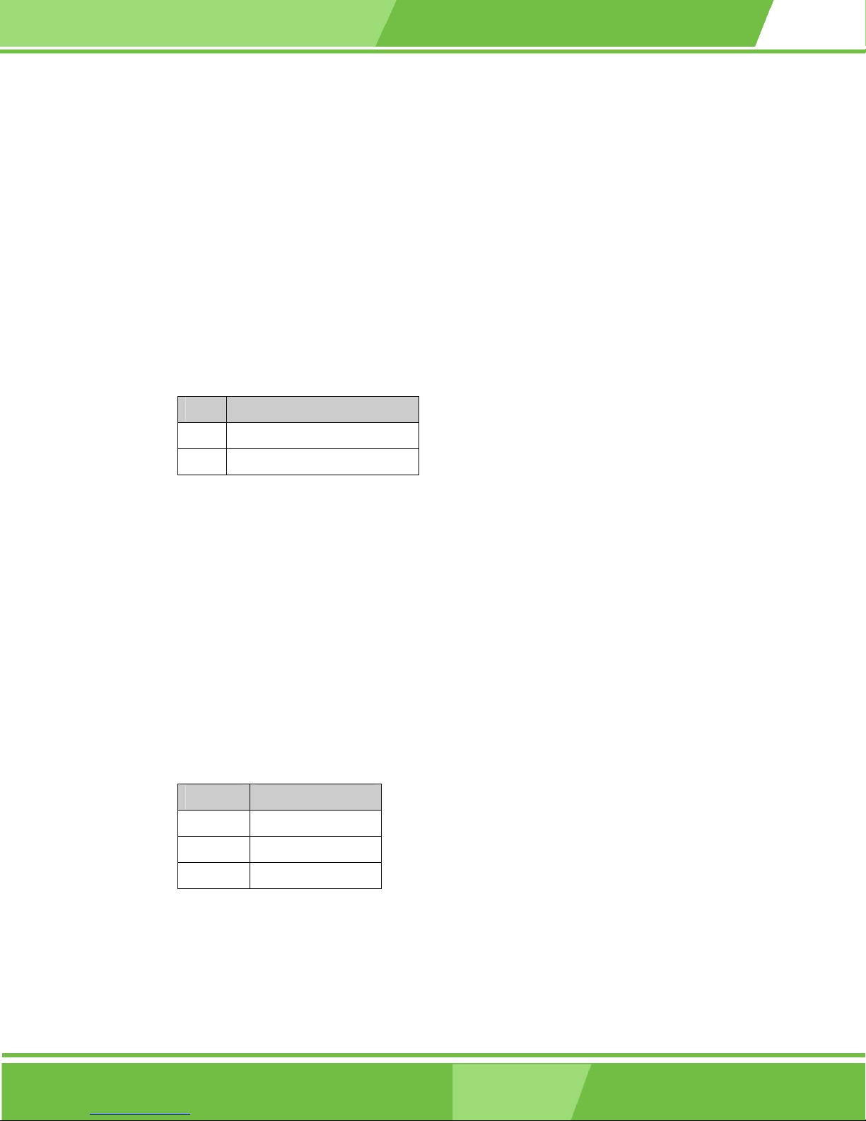
3.4.3 COM2 RS-422/485 Setup Jumper
Jumper Label: JP5
Jumper Type: 3-pin header
Jumper Settings: See Table 3-32
Jumper Location: See Figure 3-29
The JP5 jumper, when used in association with jumper JP4, sets the COM2 connector type
to RS-422 or RS-485.
JP5 Description
1-2 COM2 set to RS-422
NOVA-8450 CPU Card
2-3 COM2 set to RS-485
Table 3-32: JP5 Jumper Settings
3.4.4 COM2 Voltage Selection Jumper
Jumper Label: JP6
Jumper Type: 6-pin header (2x3 pins)
Jumper Settings: See Table 3-33
Jumper Location: See Figure 3-29
The JP6 jumper sets the COM2 port voltage.
JP6 Description
4-6
1-3, 2-4
Normal operation
+5V
3-5, 2-4
Table 3-33: JP6 Jumper Settings
+12V
81
Page 82
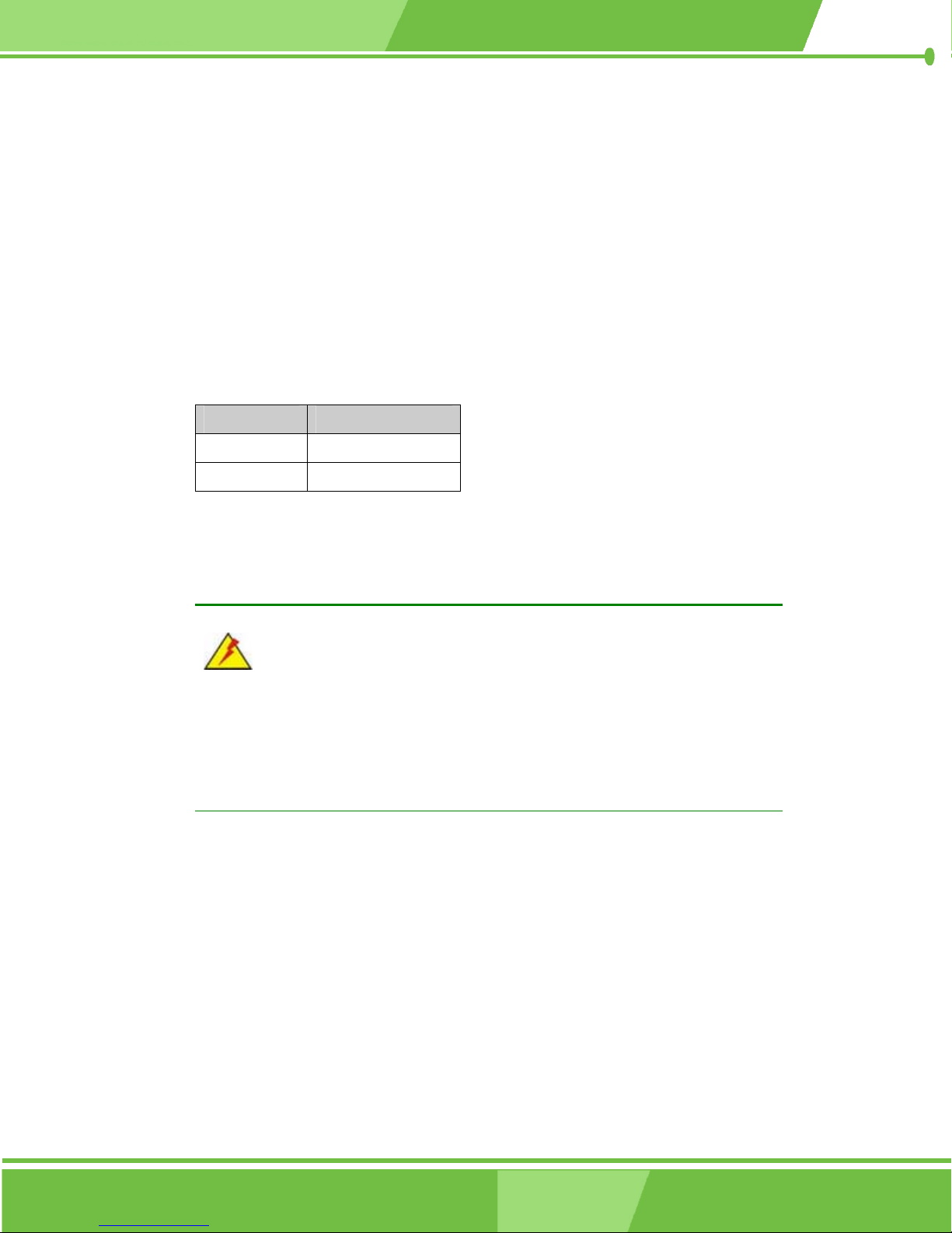
3.4.5 Compact Flash Card Setup Jumper
Jumper Label: JP2
Jumper Type: 2-pin header
Jumper Settings: See Table 3-34
Jumper Location: See Figure 3-29
The JP2 jumper sets the compact flash card to "Master" or "Slave" on the IDE bus.
JP2 Description
Closed Master
Open Slave
Table 3-34: JP2 Jumper Settings
3.4.6 LCD Panel (LVDS) Voltage select Jumper
WARNING:
Making the wrong setting on this jumper may cause irreparable damage to
both the motherboard and the LCD screen connected to the onboard
connector.
Jumper Label: JP7
Jumper Type: 6-pin header
Jumper Settings: See Table 3-35
Jumper Location: See Figure 3-29
The JP7 jumper sets the voltage to the LCD panel.
82
®
IEI
Technology, Corp.
Page 83
NOVA-8450 CPU Card
JP7 Description
1-2
3-4
5-6
Table 3-35: JP7 Jumper Settings
+3.3V
+5V
+12V
3.4.7 PC104 Plus VIO Voltage Setup Jumper
Jumper Label: JP3
Jumper Type: 3-pin header
Jumper Settings: See Table 3-36
Jumper Location: See Figure 3-29
The JP3 jumper sets the voltage to the PC/104-Plus connector.
JP3 Description
1-2 PC104 Plus VIO output voltage select 5V
2-3 PC104 Plus VIO output voltage select 3V
Table 3-36: JP3 Jumper Settings
83
Page 84

THIS PAGE IS INTENTIONALLY LEFT BLANK
84
IEI® Technology, Corp.
Page 85

NOVA-8450 CPU Card
4
Installation and
Chapter
4
Configuration
85
Page 86

4.1 Installation Considerations
NOTE:
The following installation notices and installation considerations should be
read and understood before the CPU card is installed. All installation notices
pertaining to the installation of the CPU card should be strictly adhered to.
Failing to adhere to these precautions may lead to severe damage of the
CPU card and injury to the person installing the CPU card.
4.1.1 Installation Notices
Before and during the installation of the NOVA-8450 CPU card:
Read the user manual
o The user manual provides a complete description of the NOVA-8450
CPU card, installation instructions and configuration options.
Wear an electrostatic discharge cuff (ESD)
o Electronic components are easily damaged by ESD. Wearing an ESD
cuff will remove ESD and help to prevent ESD damage.
Place the CPU card on an antistatic pad
o When installing or configuring the CPU card, place it on an antistatic
pad. This will help to prevent potential ESD damage.
Turn off all power to the NOVA-8450 CPU card
o When working with the CPU card, make sure that it is disconnected
from all power supplies and that no electricity is being fed into the
system.
Before and during the installation of the NOVA-8450 CPU card, DO NOT:
Remove any of the stickers from the PCB. These stickers are required for
warranty validation.
Use the product before verifying that all cables and power connectors are
properly connected.
Allow screws to contact the PCB, connector pins, or its components.
86
®
IEI
Technology, Corp.
Page 87

4.2 Unpacking
NOTE:
If any of the items listed below are missing when the NOVA-8450 CPU card
is unpacked, do not proceed with the installation and contact the reseller or
vendor from whom the CPU card was purchased.
4.2.1 Unpacking Precautions
Unpack the NOVA-8450 CPU card before installing it. Some components on the
NOVA-8450 are very sensitive to static electricity and can be damaged by a sudden rush of
NOVA-8450 CPU Card
power. Follow these precautions to protect the CPU card from damage:
Ground yourself to remove any static charge before touching the CPU
card by wearing a grounded wrist strap at all times or by frequently
touching any conducting material that is connected to the ground.
Handle the CPU card by its edges. Do not touch the IC chips, leads, or
circuitry if not necessary.
Do not place a PCB on top of an anti-static bag. Only the inside of the bag is safe from
static discharge.
4.2.2 Checklist
Please ensure the package contains the following items.
1 x NOVA-8450 single board computer
1 x ATA66/100 HDD cable
1 x ATA33 HDD cable
1 x Keyboard/ PS2 mouse cable
2 x SATA cable
1 x SATA Power cable
3 x RS232 cable
87
Page 88
1 x RS232/422/485 cable
1 x Audio cable
1 x USB cable
1 x VGA cable
1 x ATX 12V power cable
1 x mini jumper pack
1 x Utility CD
1 x QIG (quick installation guide)
If any of these items are missing, please contact the CPU card reseller or vendor and do
not proceed any further with the installation.
4.3 NOVA-8450 CPU Card Installation
WARNING!
The installation instructions described in this manual should be carefully
followed in order to avoid damage to the CPU card components and personal
injury.
WARNING!
1. Never run the CPU card without an appropriate heat sink and cooler.
The appropriate heat sink and cooler can be ordered from IEI
Technology or purchased separately.
2. Use the CPU 12V power connector for the CPU power.
WARNING!
When installing electronic components onto the CPU card always follow
anti-static precautions in order to prevent ESD damage to the CPU card and
other electronic components like the CPU and DIMM modules
88
®
IEI
Technology, Corp.
Page 89
The following components must be installed on, or connected to the CPU card during the
installation process.
4.3.1 CPU Installation
WARNING!
CPUs are expensive and sensitive components and CPU connector pins are
easily bent during installation. Use care to prevent damage when installing the
NOVA-8450 CPU Card
CPU
CPU cooling kit
DIMM module
Peripheral device connections
CPU module in the socket. Make sure the CPU is properly installed and that a
heat sink and cooling fan are installed before connecting power to the CPU
card. Failure to do so may damage the CPU or card.
To install an Intel® 478 Socket CPU onto the NOVA-8450 card, follow the steps below:
Step 1:
Step 2:
Step 3:
Step 4:
Step 5:
Step 6:
Make sure the CPU socket contacts are free of foreign material. Remove any
debris with compressed air.
Lift the lever on the side of the CPU socket (Figure 4-1).
Make sure there are no bent pins on the CPU and the pin 1 mark matches the
cut edge on the CPU socket (Figure 4-1).
Place the CPU on top of the socket carefully.
Insert the CPU into the socket gently.
Lower the lever into the locked position.Step 0:
89
Page 90
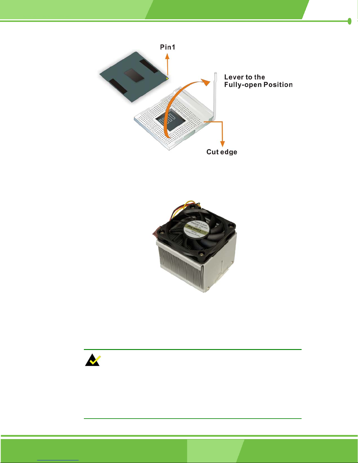
Figure 4-1: Locking the CPU into the CPU Socket
4.3.2 Optional Cooling Kit (CF-521-RS) Installation
Figure 4-2: IEI CF-521-RS Cooling Kit
IEI provides an optional cooling kit designed for Socket 478 CPUs (Figure 4-2). The
cooling kit is comprised of a CPU heat sink and a cooling fan.
NOTE:
The CF-521-RS heat sink comes with a sprayed layer of thermal paste.
Do Not wipe away the thermal paste while unpacking or installing the heat
sink. Thermal paste between the CPU and the heat sink is important for
optimum heat dissipation.
90
®
IEI
Technology, Corp.
Page 91
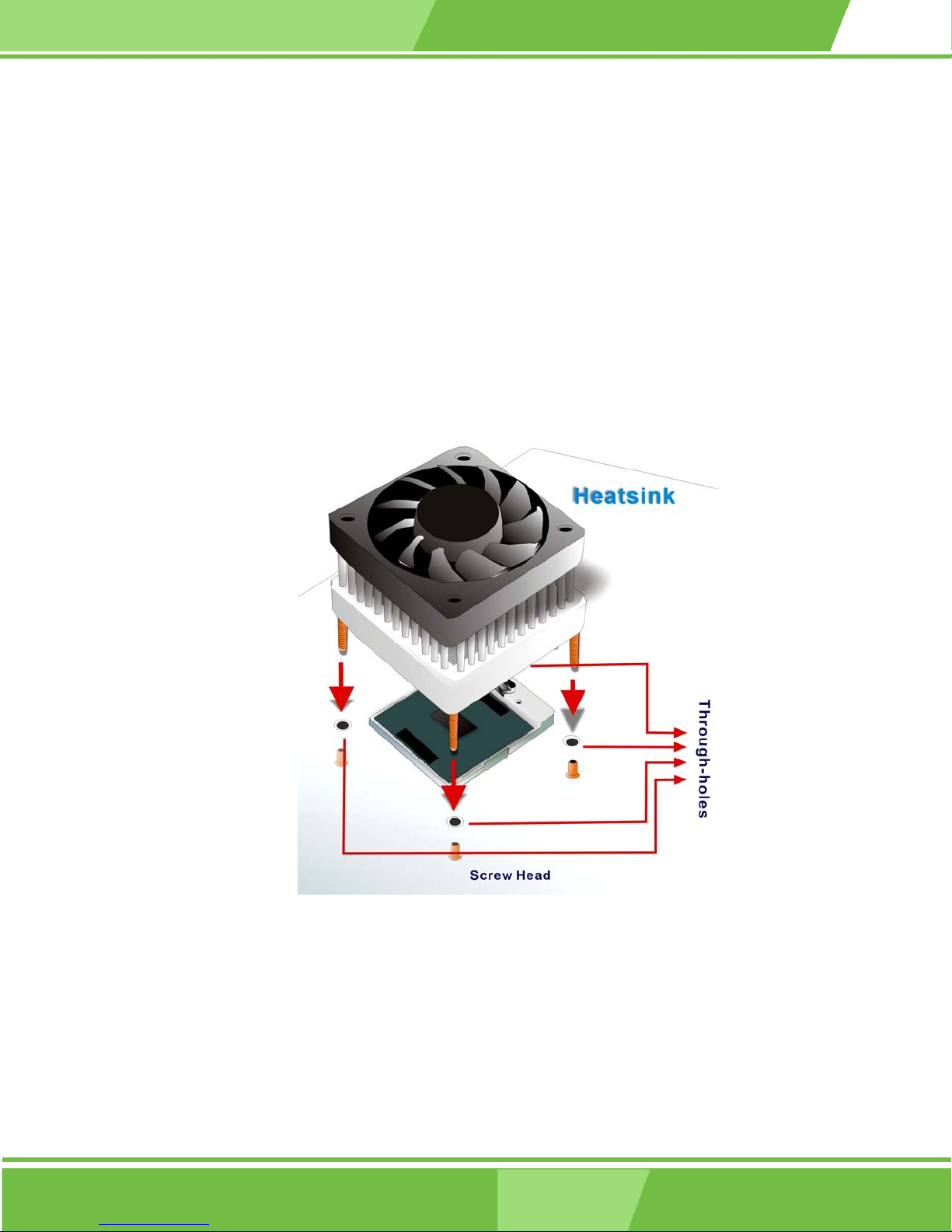
NOVA-8450 CPU Card
To install the CF-521-RS cooling kit, follow the steps below.
Step 1:
Step 2:
Step 3:
Place the cooling kit onto the CPU. Make sure the CPU cable can be properly
routed when the cooling kit is installed.
Properly align the cooling kit. Make sure the four threaded screw fasteners can
pass through the pre-drilled holes on the PCB.
Align the nut caps with the heat sink screw threads that protrude through the
PCB holes. Secure the cooling kit to the PCB card without over tightening the
nut caps (Figure 4-3).
Figure 4-3: Securing the Cooling Kit
Step 4:
Connect the cooling kit fan cable to the FAN1 connector on the CPU card.
Carefully route the cable and avoid chips and fan blades (Figure 4-4).Step 0:
91
Page 92
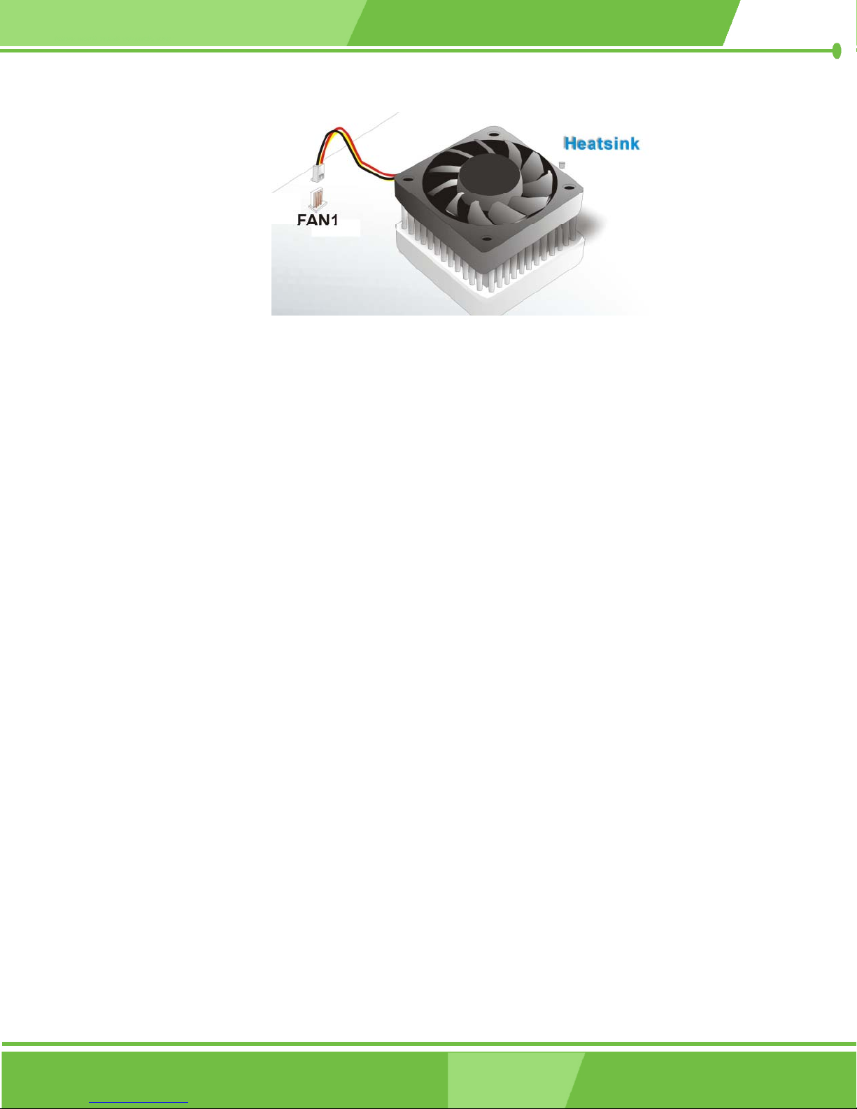
Figure 4-4: Connect the Cooling Fan Cable
4.3.3 DIMM Module Installation
4.3.3.1 Purchasing the Memory Module
The DIMM module can support a memory chip with a maximum size of 1GB.
4.3.3.2 DIMM Module Installation
The NOVA-8450 CPU card has one DDR SDRAM DIMM socket. Follow the steps below to
install the DIMM module.
Step 1:
Make sure the two handles of the DIMM socket are in the "open" position,
leaning outward (Figure 4-5).
92
®
IEI
Technology, Corp.
Page 93
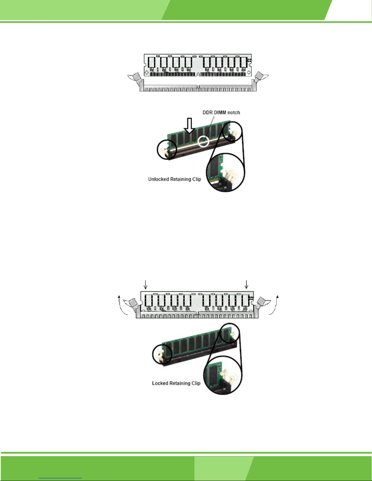
NOVA-8450 CPU Card
Figure 4-5: Installing the DIMM Module
Step 2:
Slowly slide the DIMM module along the plastic guides on both ends of the
socket. Press the DIMM module down into the socket until it clicks into position
and the two handles have automatically locked the memory module into place
(Figure 4-6).
Figure 4-6: Locking the DIMM Module
93
Page 94
Step 3: To remove the memory module, push both handles outward, and the memory
module is ejected by the mechanism in the socket.Step 0:
4.3.4 Peripheral Device Connection
Cables provided by IEI that connect peripheral devices to the CPU card are listed in Table
4-1. Cables not included in the kit must be purchased separately.
Quantity Type
1 ATA66/100 HDD cable
1 ATA33 HDD cable
1 Keyboard/PS2 mouse cable
2 SATA cable
1 SATA Power cable
3 RS232 cable
1 RS232/422/485 cable
1 Audio cable
1 USB cable
1 VGA cable
1 ATX 12V power cable
1 mini jumper pack
Table 4-1: IEI Provided Cables
4.3.4.1 Compact Flash Disk
When appropriately formatted, a compact Flash disk can serve as a bootable hard drive in
applications where installation space is limited. The Compact Flash card occupies a
secondary IDE channel.
4.3.4.2 IDE Disk Drive Connector (IDE1, IDE2)
The cables used to connect the CPU card to an IDE HDD are standard 44-pin ATA33 and
40-pin ATA 66/100 flat cables. Follow the instructions below to connect an IDE HDD to the
CPU card.
Step 1: Find the ATA33 or ATA 66/100 flat cable in the kit that came with the CPU card.
94
IEI® Technology, Corp.
Page 95
NOVA-8450 CPU Card
Step 2:
Step 3:
Step 4:
Connect one end of the cable to the IDE1 or IDE2 connector on the CPU card. A
keyed pin on the IDE connectors prevents them from being connected
incorrectly.
Locate the red wire on the cable that corresponds to the pin 1 connector.
Connect the cable to the HDD making sure that the pin 1 cable corresponds to
pin 1 on the connector.Step 0:
NOTE:
When two EIDE disk drives are connected together, back-end jumpers on
the drives must be used to configure one drive as a master and the other as
a slave.
4.3.4.3 Parallel Port Connector (LPT1)
The onboard parallel port connector (LPT1) connects to a printer. The NOVA-8450 comes
with a multi-mode (ECP/EPP/SPP) parallel port. The parallel port interface features a
26-pin flat-cable connector that requires an adapter cable if a traditional DB-25 connector is
used. The parallel port interface can be re-assigned to LPT2 or LPT3 through the BIOS
configuration utility. The default interrupt channel is IRQ7. Select ECP or EPP DMA mode
using the BIOS configuration utility.
4.3.4.4 Audio Interface
AC’97 Audio signals are interfaced through a 12-pin flat-cable connector. The signals
include microphone line-in, line-in stereo, line-out stereo and speaker out stereo. An audio
12-pin-to-phone-jack adapter kit is required.
4.3.4.5 COM Port Connectors [COM1, COM2, COM3 and COM4]
The NOVA-8450 provides four serial ports (COM1, COM3, COM4: RS-232; COM2:
RS-422/485) interfaced through three 10-pin male headers (COM1, COM3, COM4) and
95
Page 96

one 14-pin male header (COM2). The serial ports facilitate the connection to serial devices
or a communications network, e.g., terminal console.
4.3.4.6 VGA Connector
The PCI SVGA interface on the NOVA-8450 connects conventional CRT displays and flat
panel displays including passive LCD and active LCD displays. There are two (2)
connectors onboard:
CRT VGA monitors
LVDS type LCD panels
Pin assignments for the connectors can be found in Section 3.
4.3.4.7 LVDS Connector
LVDS1 is a 30-pin connector connecting a dual 24-bit LCD panel. Adapter cables are
required for connecting the display connectors.
4.4 Jumper Configuration
The NOVA-8450 CPU card has seven onboard jumpers:
Clear CMOS Setup (JP1)
COM2 RS-232/422/485 Setup (JP4)
COM2 RS-422/485 Setup (JP5)
COM2 Voltage Selection (JP6)
Compact Flash Card Setup (JP2)
LCD Panel (LVDS) Voltage Select (JP7)
PC104 Plus VIO Voltage Setup (JP3)
Make sure the jumper settings are properly configured before the NOVA-8450 CPU card is
installed into a chassis. For more information about jumper settings and configurations,
refer to Section 3.4.
96
IEI® Technology, Corp.
Page 97

4.5 Chassis Installation
The CPU card can be mounted into a chassis only after the CPU, the cooling kit, and the
DIMM module has been installed, the internal peripheral connectors have been connected
to the peripheral devices and the jumpers have been configured.
Refer to the chassis user guide for instructions on how to mount the CPU card into a
chassis.
4.6 Rear Panel Connectors
The rear panel RJ-45 connectors can be connected to an external LAN and communicate
with data transfer rates up to 1Gb/s.
NOVA-8450 CPU Card
97
Page 98

THIS PAGE IS INTENTIONALLY LEFT BLANK
98
IEI® Technology, Corp.
Page 99

NOVA-8450 CPU Card
Chapter
5
5
AMI BIOS Setup
99
Page 100

5.1 Introduction
A licensed copy of AMI BIOS is preprogrammed into the ROM BIOS. The BIOS setup
program allows modifications to the basic system configuration. This chapter describes
how to access the BIOS setup program and the configuration options.
5.1.1 Starting Setup
The AMI BIOS is activated when the computer starts. The setup program can be activated
in one of two ways.
1. Press the D
2. Press the DELETE key when the Press Del to enter SETUP message
appears on the screen.0.
If the message disappears before you respond, restart the computer and try again.
ELETE key as soon as the system starts.
5.1.2 Using Setup
Use the arrow keys to highlight items, press ENTER to select, use the PAGE UP and PAGE
DOWN keys to change entries, press F1 for help and press ESC to quit.
100
IEI® Technology, Corp.
 Loading...