

IEI Technology NANO-BT-i1-J19001, NANO-BT-i1-N28071, NANO-BT-i1-N29301, NANO-BT-E38451W2 User Manual
Page 1
®
NANO-BT EPIC SBC
MODEL:
NANO-BT Series
EPIC SBC with 22nm Intel® Atom or Celeron
Dual GbE, DDR3, HDMI, VGA, LVDS, USB 2.0/3.0, COM Ports
Two SATA 3Gb/s Ports, IPMI 2.0 and RoHS
User Manual
SoC,
Rev. 1.12 – August 10, 2016
Page i
Page 2

NANO-BT EPIC SBC
Revision
Date Version Changes
August 10, 2016 1.12 Modified power connector (CN10) orientation
October 28, 2015 1.11 Updated Figure 1-4: NANO-BT Main Dimensions (mm)
June 4, 2015 1.10 Updated for R11 version
October 1, 2014 1.03 Updated Section 1.6: Dimensions
June 27, 2014 1.02 Updated supported memory specifications in Chapter 1.
May 7, 2014 1.01 Updated Section 1.6: Dimensions
Updated Chapter 6: Software Drivers
Updated Table 3-15: LVDS Connector Pinouts
April 3, 2014 1.00 Initial release
Page ii
Page 3

NANO-BT EPIC SBC
COPYRIGHT NOTICE
The information in this document is subject to change without prior notice in order to
improve reliability, design and function and does not represent a commitment on the part
of the manufacturer.
In no event will the manufacturer be liable for direct, indirect, special, incidental, or
consequential damages arising out of the use or inability to use the product or
documentation, even if advised of the possibility of such damages.
This document contains proprietary information protected by copyright. All rights are
Copyright
reserved. No part of this manual may be reproduced by any mechanical, electronic, or
other means in any form without prior written permission of the manufacturer.
TRADEMARKS
All registered trademarks and product names mentioned herein are used for identification
purposes only and may be trademarks and/or registered trademarks of their respective
owners.
Page iii
Page 4

NANO-BT EPIC SBC
Manual Conventions
WARNING
Warnings appear where overlooked details may cause damage to the
equipment or result in personal injury. Warnings should be taken
seriously.
CAUTION
Cautionary messages should be heeded to help reduce the chance of
losing data or damaging the product.
NOTE
These messages inform the reader of essential but non-critical
information. These messages should be read carefully as any directions
or instructions contained therein can help avoid making mistakes.
HOT SURFACE
This symbol indicates a hot surface that should not be touched without
taking care.
Page iv
Page 5

NANO-BT EPIC SBC
Table of Contents
1 INTRODUCTION.......................................................................................................... 1
1.1 INTRODUCTION........................................................................................................... 2
1.2 MODEL VARIATIONS................................................................................................... 3
1.3 BENEFITS ................................................................................................................... 4
1.4 FEATURES................................................................................................................... 4
1.5 CONNECTORS ............................................................................................................. 5
1.6 DIMENSIONS............................................................................................................... 7
1.7 DATA FLOW................................................................................................................ 9
1.8 TECHNICAL SPECIFICATIONS .................................................................................... 10
2 PACKING LIST........................................................................................................... 13
2.1 ANTI-STATIC PRECAUTIONS...................................................................................... 14
2.2 UNPACKING PRECAUTIONS....................................................................................... 14
2.3 PACKING LIST........................................................................................................... 15
2.4 OPTIONAL ITEMS...................................................................................................... 16
3 CONNECTORS ........................................................................................................... 17
3.1 PERIPHERAL INTERFACE CONNECTORS..................................................................... 18
3.1.1 NANO-BT Layout............................................................................................. 18
3.1.2 Peripheral Interface Connectors ..................................................................... 19
3.1.3 External Interface Panel Connectors............................................................... 21
3.2 INTERNAL PERIPHERAL CONNECTORS...................................................................... 22
3.2.1 +12 V Power Connector.................................................................................. 22
3.2.2 Audio Connector .............................................................................................. 23
3.2.3 Battery Connector............................................................................................ 24
3.2.4 Backlight Inverter Connector .......................................................................... 25
3.2.5 Buzzer Connector............................................................................................. 26
3.2.6 Chassis Intrusion Connector............................................................................ 27
3.2.7 Digital I/O Connector...................................................................................... 28
3.2.8 Fan Connector (CPU)...................................................................................... 29
3.2.9 Fan Connector (System) .................................................................................. 30
Page v
Page 6

NANO-BT EPIC SBC
3.2.10 Front Panel Connector.................................................................................. 31
3.2.11 IPMI LED Connector..................................................................................... 32
3.2.12 iRIS Module Slot (NANO-BT
-i1 Models Only).............................................. 33
3.2.13 LAN LED Connectors.................................................................................... 34
3.2.14 LVDS Connector............................................................................................ 35
3.2.15 Memory Card Slot.......................................................................................... 36
3.2.16 microSD Card Slot (E38xx Models Only)...................................................... 37
3.2.17 PCI-104 Connector........................................................................................ 37
3.2.18 PCIe Mini Card Slot ...................................................................................... 39
3.2.19 Power Button Connector................................................................................ 41
3.2.20 Power Button ................................................................................................. 41
3.2.21 Reset Button Connector ................................................................................. 42
3.2.22 SATA 3Gb/s Drive Connectors....................................................................... 43
3.2.23 SATA Power Connectors................................................................................ 44
3.2.24 Serial Port Connectors, RS-232..................................................................... 45
3.2.25 Serial Port Connector, RS-422/485................................................................ 46
3.2.26 SMBus Connector .......................................................................................... 47
3.2.27 SPI Flash Connector...................................................................................... 48
3.2.28 SPI Flash Connector, EC............................................................................... 49
3.2.29 USB 2.0 Connector ........................................................................................ 50
3.3
EXTERNAL PERIPHERAL INTERFACE CONNECTOR PANEL ......................................... 51
3.3.1 Ethernet Connectors ........................................................................................ 51
3.3.2 HDMI Connector............................................................................................. 52
3.3.3 Keyboard/Mouse Connector............................................................................ 53
3.3.4 USB 2.0 Connector .......................................................................................... 54
3.3.5 USB 3.0 Connector .......................................................................................... 55
3.3.6 VGA Connector................................................................................................ 55
4 INSTALLATION .........................................................................................................57
ANTI-STATIC PRECAUTIONS...................................................................................... 58
4.1
4.2 INSTALLATION CONSIDERATIONS.............................................................................. 58
4.2.1 SO-DIMM Installation..................................................................................... 60
4.2.2 iRIS-1010 Module Installation (Optional)....................................................... 60
4.2.3 PCIe Mini Card Installation............................................................................ 62
4.3 SYSTEM CONFIGURATION......................................................................................... 62
Page vi
Page 7

NANO-BT EPIC SBC
4.3.1 AT/ATX Power Mode Setting........................................................................... 62
4.3.2 Clear CMOS Button......................................................................................... 63
4.3.3 LVDS Panel Resolution Selection.................................................................... 64
4.3.4 LCD Voltage Selection..................................................................................... 65
4.3.5 mSATA/SATA Selection..................................................................................... 66
4.3.6 PCI-104 Voltage Selection............................................................................... 67
4.3.7 USB Power Select............................................................................................ 67
INTERNAL PERIPHERAL DEVICE CONNECTIONS........................................................ 68
4.4
4.4.1 AT Power Connection...................................................................................... 68
4.4.2 SATA Drive Connection ................................................................................... 69
4.4.3 Single RS-232 Cable Connection..................................................................... 70
4.5
IPMI SETUP PROCEDURE (FOR NANO-BT-I1 MODELS ONLY)................................. 71
4.5.1 Managed System Hardware Setup ................................................................... 71
5 BIOS.............................................................................................................................. 72
5.1 INTRODUCTION......................................................................................................... 73
5.1.1 Starting Setup................................................................................................... 73
5.1.2 Using Setup...................................................................................................... 73
5.1.3 Getting Help..................................................................................................... 74
5.1.4 Unable to Reboot after Configuration Changes.............................................. 74
5.1.5 BIOS Menu Bar................................................................................................ 74
5.2 MAIN........................................................................................................................ 75
5.3 ADVANCED............................................................................................................... 76
5.3.1 ACPI Settings................................................................................................... 77
5.3.2 F81866 Super IO Configuration
...................................................................... 78
5.3.2.1 Serial Port n Configuration....................................................................... 78
5.3.3 iWDD H/W Monitor......................................................................................... 83
5.3.3.1 Smart Fan Mode Configuration................................................................ 84
5.3.4 RTC Wake Settings........................................................................................... 86
5.3.5 Serial Port Console Redirection...................................................................... 87
5.3.6 IEI Feature....................................................................................................... 90
5.3.7 CPU Configuration.......................................................................................... 91
5.3.8 IDE Configuration........................................................................................... 93
5.3.9 USB Configuration........................................................................................... 94
5.4 CHIPSET ................................................................................................................... 95
Page vii
Page 8

NANO-BT EPIC SBC
5.4.1 North Bridge .................................................................................................... 96
5.4.1.1 Intel IGD Configuration............................................................................ 96
5.4.2 South Bridge..................................................................................................... 99
5.4.2.1 PCI Express Configuration..................................................................... 100
SECURITY............................................................................................................... 101
5.5
5.6 BOOT...................................................................................................................... 102
5.7 EXIT....................................................................................................................... 104
6 SOFTWARE DRIVERS............................................................................................ 106
6.1 SOFTWARE INSTALLATION...................................................................................... 107
6.2 AVAILABLE SOFTWARE DRIVERS ............................................................................ 109
A REGULATORY COMPLIANCE.............................................................................111
B PRODUCT DISPOSAL.............................................................................................113
C BIOS OPTIONS.........................................................................................................115
D TERMINOLOGY ......................................................................................................118
E WA TCHDOG TIMER............................................................................................... 123
F DIGITAL I/O INTERFACE ..................................................................................... 126
F.1
INTRODUCTION....................................................................................................... 127
F.2 ASSEMBLY LANGUAGE SAMPLE 1........................................................................... 128
F.3 ASSEMBLY LANGUAGE SAMPLE 2........................................................................... 128
G HAZARDOUS MATERIALS DISCLOSURE....................................................... 129
Page viii
Page 9

NANO-BT EPIC SBC
List of Figures
Figure 1-1: NANO-BT......................................................................................................................2
Figure 1-2: Connectors (Front Side).............................................................................................5
Figure 1-3: Connectors (Solder Side)...........................................................................................6
Figure 1-4: NANO-BT Main Dimensions (mm).............................................................................7
Figure 1-5: NANO-BT Height Dimensions 1 (mm).......................................................................8
Figure 1-6: NANO-BT Height Dimensions 2 (mm).......................................................................8
Figure 1-7: Data Flow Diagram......................................................................................................9
Figure 3-1: Connectors and Jumpers (Front Side) ...................................................................18
Figure 3-2: Connectors and Jumpers (Solder Side) .................................................................19
Figure 3-3: CPU Power Connector Location..............................................................................22
Figure 3-4: Audio Connector Location.......................................................................................23
Figure 3-5: Battery Connector Location.....................................................................................24
Figure 3-6: Backlight Inverter Connector Location...................................................................25
Figure 3-7: Buzzer Connector Location .....................................................................................26
Figure 3-8: Chassis Intrusion Connector Location...................................................................27
Figure 3-9: Digital I/O Connector Location ................................................................................28
Figure 3-10: CPU Fan Connector Location................................................................................29
Figure 3-11: System Fan Connector Location...........................................................................30
Figure 3-12: Front Panel Connector Location ...........................................................................31
Figure 3-13: IPMI LED Connector Location ...............................................................................32
Figure 3-14: iRIS Module Slot Location......................................................................................33
Figure 3-15: LAN LED Connector Locations .............................................................................34
Figure 3-16: LVDS Connector Location......................................................................................35
Figure 3-17: Memory Card Slot Location ...................................................................................36
Figure 3-18: microSD Card Slot Location..................................................................................37
Figure 3-19: PCI-104 Connector Location..................................................................................38
Figure 3-20: PCIe Mini Card Slot Location.................................................................................39
Figure 3-21: Power Button Location...........................................................................................41
Figure 3-22: Power Button Location...........................................................................................42
Figure 3-23: Reset Button Connector Location.........................................................................42
Page ix
Page 10

Figure 3-24: SATA 3Gb/s Drive Connector Locations..............................................................43
Figure 3-25: SATA Power Connector Locations .......................................................................44
Figure 3-26: RS-232 Serial Port Connector Locations..............................................................45
Figure 3-27: RS-422/485 Connector Location............................................................................46
Figure 3-28: SMBus Connector Location...................................................................................47
Figure 3-29: SPI Flash Connector Location...............................................................................48
Figure 3-30: SPI EC Flash Connector Location.........................................................................49
Figure 3-31: USB 2.0 Connector Location .................................................................................50
Figure 3-32: External Peripheral Interface Connector..............................................................51
Figure 3-33: Ethernet Connector.................................................................................................52
Figure 3-34: HDMI Connector......................................................................................................53
Figure 3-35: PS/2 Pinout and Configuration..............................................................................54
Figure 3-36: VGA Connector .......................................................................................................56
Figure 4-1: SO-DIMM Installation................................................................................................60
NANO-BT EPIC SBC
Figure 4-2: iRIS-1010 Module Installation ..................................................................................61
Figure 4-3: PCIe Mini Card Installation.......................................................................................62
Figure 4-4: AT/ATX Power Mode Switch Location....................................................................63
Figure 4-5: Clear CMOS Button Location...................................................................................63
Figure 4-6: LVDS Panel Resolution Selection Switch Location ..............................................65
Figure 4-7: LCD Voltage Selection Switch Location.................................................................66
Figure 4-8: mSATA/SATA Switch Location................................................................................66
Figure 4-9: PCI-104 Voltage Switch Location ............................................................................67
Figure 4-10: Power Cable to Motherboard Connection............................................................68
Figure 4-11: Connect Power Cable to Power Supply................................................................69
Figure 4-12: SATA Drive Cable Connection...............................................................................70
Figure 4-13: Single RS-232 Cable Installation ...........................................................................71
Figure 6-1: Driver CD Main Menu............................................................................................. 108
Figure 6-2: Available Drivers.................................................................................................... 108
Page x
Page 11

NANO-BT EPIC SBC
List of Tables
Table 1-1: Model Variations...........................................................................................................3
Table 1-2: NANO-BT Specifications............................................................................................12
Table 2-1: Packing List.................................................................................................................16
Table 2-2: Optional Items.............................................................................................................16
Table 3-1: Peripheral Interface Connectors...............................................................................21
Table 3-2: Rear Panel Connectors..............................................................................................21
Table 3-3: CPU Power Connector Pinouts.................................................................................22
Table 3-4: Audio Connector Pinouts ..........................................................................................23
Table 3-5: Battery Connector Pinouts........................................................................................24
Table 3-6: Backlight Inverter Connector Pinouts......................................................................25
Table 3-7: Chassis Intrusion Connector Pinouts......................................................................27
Table 3-8: Digital I/O Connector Pinouts....................................................................................28
Table 3-9: CPU Fan Connector Pinouts......................................................................................29
Table 3-10: System Fan Connector Pinouts..............................................................................30
Table 3-11: Front Panel Connector Pinouts...............................................................................31
Table 3-12: IPMI LED Connector Pinouts...................................................................................32
Table 3-13: LAN1 LED Connector (JP8) Pinouts.......................................................................34
Table 3-14: LAN2 LED Connector (JP9) Pinouts.......................................................................34
Table 3-15: LVDS Connector Pinouts.........................................................................................36
Table 3-16: PCI-104 Connector Pinouts .....................................................................................39
Table 3-17: PCIe Mini Card Slot Pinouts ....................................................................................40
Table 3-18: Power Button Pinouts..............................................................................................41
Table 3-19: Reset Button Connector Pinouts............................................................................42
Table 3-20: SATA 3Gb/s Drive Connector Pinouts....................................................................43
Table 3-21: SATA Power Connector Pinouts.............................................................................44
Table 3-22: RS-232 Serial Port Connector Pinouts...................................................................45
Table 3-23: RS-422/485 Connector Pinouts...............................................................................46
Table 3-24: RS-422/485 Pinouts of D-sub 9 Connector.............................................................47
Table 3-25: SMBus Connector Pinouts ......................................................................................48
Table 3-26: SPI Flash Connector Pinouts ..................................................................................48
Page xi
Page 12

Table 3-27: SPI EC Flash Connector Pinouts ............................................................................49
Table 3-28: USB 2.0 Connector Pinouts.....................................................................................50
Table 3-29: LAN1 Ethernet Connector Pinouts .........................................................................51
Table 3-30: LAN2 Ethernet Connector Pinouts .........................................................................52
Table 3-31: Connector LEDs........................................................................................................52
Table 3-32: HDMI Connector Pinouts .........................................................................................53
Table 3-33: Keyboard Connector Pinouts..................................................................................54
Table 3-34: USB 2.0 Port Pinouts................................................................................................54
Table 3-35: USB 3.0 Port Pinouts................................................................................................55
Table 3-36: VGA Connector Pinouts...........................................................................................56
Table 4-1: LVDS Panel Resolution Selection.............................................................................64
Table 4-2: LCD Voltage Selection Switch Settings ...................................................................65
Table 4-3: mSATA/SATA Switch Settings..................................................................................66
Table 4-4: PCI-104 Voltage Switch Settings...............................................................................67
NANO-BT EPIC SBC
Table 5-1: BIOS Navigation Keys................................................................................................74
Page xii
Page 13

NANO-BT EPIC SBC
BIOS Menus
BIOS Menu 1: Main.......................................................................................................................75
BIOS Menu 2: Advanced..............................................................................................................76
BIOS Menu 3: ACPI Configuration..............................................................................................77
BIOS Menu 4: F81866 Super IO Configuration ..........................................................................78
BIOS Menu 5: Serial Port n Configuration Menu.......................................................................78
BIOS Menu 6: iWDD H/W Monitor................................................................................................83
BIOS Menu 7: Smart Fan Mode Configuration ..........................................................................84
BIOS Menu 8: RTC Wake Settings..............................................................................................86
BIOS Menu 9: Serial Port Console Redirection.........................................................................87
BIOS Menu 10: IEI Feature...........................................................................................................90
BIOS Menu 11: CPU Configuration.............................................................................................91
BIOS Menu 12: IDE Configuration...............................................................................................93
BIOS Menu 13: USB Configuration.............................................................................................94
BIOS Menu 14: Chipset................................................................................................................95
BIOS Menu 15: North Bridge.......................................................................................................96
BIOS Menu 16: Intel IGD Configuration......................................................................................96
BIOS Menu 17: South Bridge.......................................................................................................99
BIOS Menu 18: PCI Express Configuration ............................................................................ 100
BIOS Menu 19: Security............................................................................................................ 101
BIOS Menu 20: Boot.................................................................................................................. 102
BIOS Menu 21:Exit..................................................................................................................... 104
Page xiii
Page 14

Page 15

NANO-BT EPIC SBC
Chapter
1
1 Introduction
Page 1
Page 16

1.1 Introduction
Figure 1-1: NANO-BT
The NANO-BT series is an EPIC form factor single bard computer. It has an on-board
22nm Intel® Atom™ or Celeron® processor, and supports one 204-pin 1333/1066 MHz
NANO-BT EPIC SBC
dual-channel unbuffered DDR3 Low Voltage (DDR3L) SDRAM SO-DIMM with up to
8.0 GB of memory.
The NANO-BT-i1 models feature Intelligent Platform Management Interface (IPMI) that
helps lower the overall costs of server management by enabling users to maximize IT
resource, save time and manage multiple systems. The NANO-BT-i1 supports IPMI 2.0
through the optional iRIS-1010 module.
The NANO-BT includes one VGA port and one HDMI port for dual independent display It
also has an internal 18-bit/24-bit dual-channel LVDS connector supporting up to 1920 x
1200 resolutions. Expansion and I/O include one PCI-104 slot, one PCIe Mini slot, one
USB 3.0 port plus one USB 2.0 on the rear panel, two USB 2.0 by pin header, two SATA
3Gb/s connectors, three RS-232 serial ports, and one PS/2 keyboard/mouse connector.
Page 2
Page 17
NANO-BT EPIC SBC
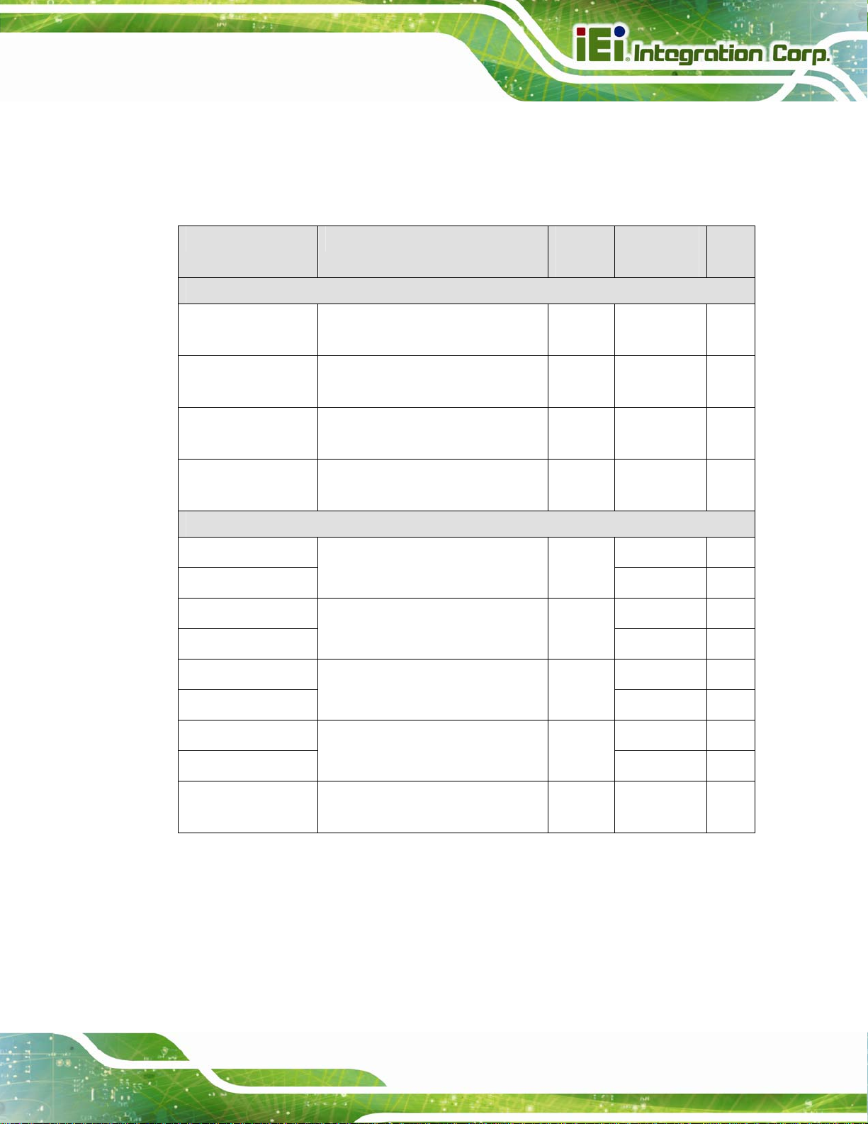
1.2 Model Variations
There are several models of the NANO-BT series. The model variations are listed in
Table 1-1.
Model On-board SoC Max.
Memory
Standard
NANO-BT-i1-J19001 Intel® Celeron® processor J1900
(2 GHz, quad-core, 2 MB cache)
NANO-BT-i1-N28071 Intel® Celeron® processor N2807
(1.58 GHz, dual-core, 2 MB cache)
NANO-BT-i1-N29301 Intel® Celeron® processor N2930
(1.83 GHz, quad-core, 2 MB cache)
NANO-BT-E38451W2 Intel® Atom™ processor E3845
(1.91 GHz, quad-core, 2 MB cache)
By Request (MOQ: 100 pcs/lot)
NANO-BT-i1-E38151
NANO-BT-E38151W2
NANO-BT-i1-E38251
NANO-BT-E38251W2
Intel® Atom™ processor E3815
(1.46 GHz, single-core, 512 KB cache)
Intel® Atom™ processor E3825
(1.33 GHz, dual-core, 1 MB cache)
8 GB -20ºC–60ºC Yes
4 GB -20ºC–60ºC Yes
8 GB -20ºC–60ºC Yes
8 GB -40ºC–85ºC No
4 GB
4 GB
Operating
Temp.
-20ºC–60ºC Yes
-40ºC–85ºC No
-20ºC–60ºC Yes
-40ºC–85ºC No
iRIS
NANO-BT-i1-E38261
NANO-BT-E38261W2
NANO-BT-i1-E38271
NANO-BT-E38271W2
NANO-BT-i1-E38451 Intel® Atom™ processor E3845
Intel® Atom™ processor E3826
(1.46 GHz, dual-core, 1 MB cache)
Intel® Atom™ processor E3827
(1.75 GHz, dual-core, 1 MB cache)
(1.91 GHz, quad-core, 2 MB cache)
8 GB
8 GB
8 GB -20ºC–60ºC Yes
-20ºC–60ºC Yes
-40ºC–85ºC No
-20ºC–60ºC Yes
-40ºC–85ºC No
Table 1-1: Model Variations
Page 3
Page 18

1.3 Benefits
Some of the NANO-BT motherboard benefits include:
1.4 Features
Some of the NANO-BT motherboard features are listed below:
NANO-BT EPIC SBC
Powerful graphics with multiple monitors
Staying connected with both wired LAN connections
Speedy running of multiple programs and applications
EPIC form factor
RoHS compliant
On-board 22nm Intel® Atom or Celeron® processor
One 204-pin 1333/1066 MHz dual-channel unbuffered DDR3L (1.35 V)
SDRAM SO-DIMM slot supports up to 8.0 GB of memory
LVDS, VGA and HDMI interfaces for dual independent display
Supports IPMI 2.0 via IEI iRIS-1010 module
Two Intel® PCIe GbE connectors
Two SATA 3Gb/s connectors
One full-size PCIe Mini card expansion slot
One PCI-104 expansion slot
One USB 3.0 port and three USB 2.0 ports
Three RS-232 serial ports and one RS-422/485 serial port
High Definition Audio
Page 4
Page 19

NANO-BT EPIC SBC
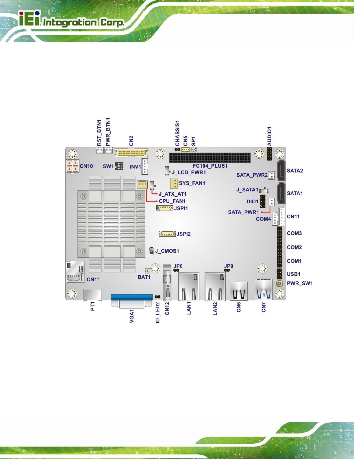
1.5 Connectors
The connectors on the NANO-BT are shown in the figure below.
Figure 1-2: Connectors (Front Side)
Page 5
Page 20
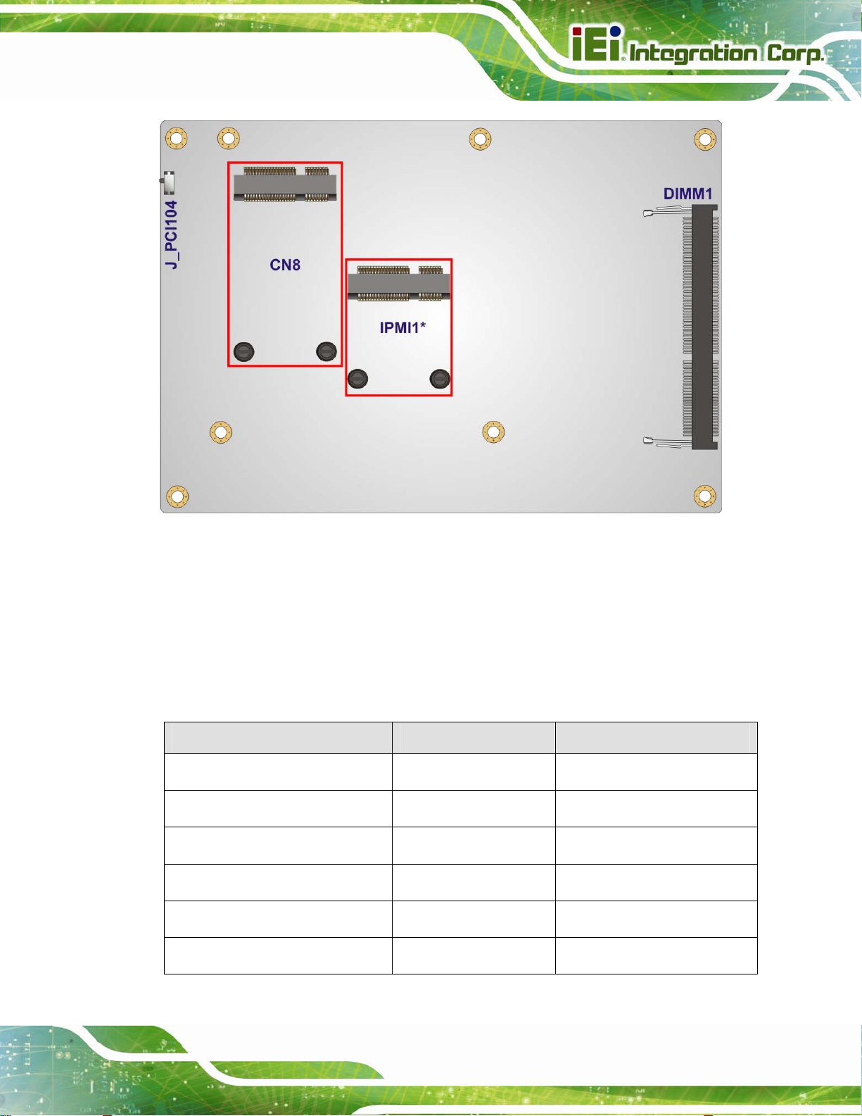
NANO-BT EPIC SBC
Figure 1-3: Connectors (Solder Side)
Page 6
Page 21
NANO-BT EPIC SBC
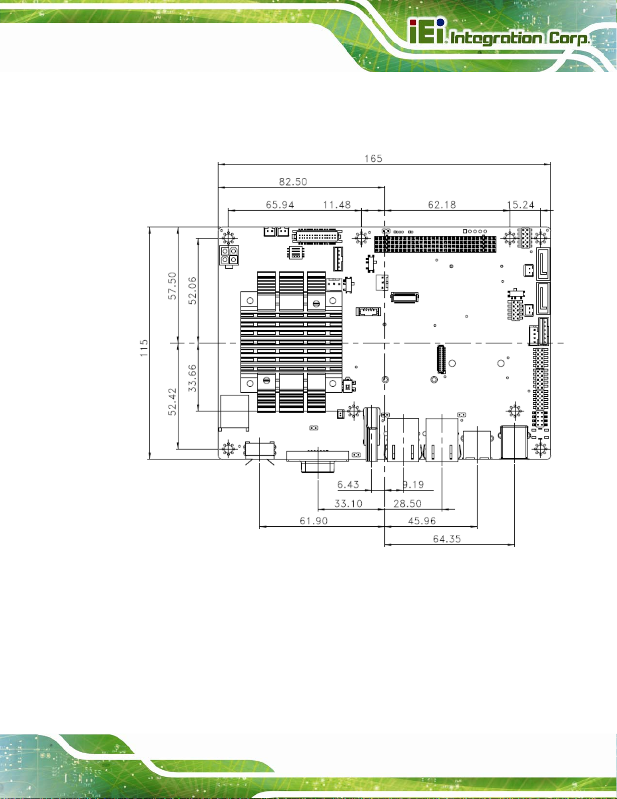
1.6 Dimensions
The main dimensions of the NANO-BT are shown in the diagram below.
Figure 1-4: NANO-BT Main Dimensions (mm)
Page 7
Page 22

The height of the NANO-BT series varies depending on the heatsink installed on the
NANO-BT EPIC SBC
board. Figure 1-5 sho
NANO-BT-i1-E38271
NANO-BT-i1-E38261
NANO-BT-i1-E38251
NANO-BT-i1-E38151
NANO-BT-i1-N28071
Figure 1-5: NANO-BT Height Dimensions 1 (mm)
ws the height dimensions of the following models:
Figure 1-6 sh
Figure 1-6: NANO-BT Height Dimensions 2 (mm)
ows the height dimensions of the following models:
NANO-BT-i1-E38451
NANO-BT-i1-J19001
NANO-BT-i1-N29301
NANO-BT-E38xx1W2
Page 8
Page 23

NANO-BT EPIC SBC
1.7 Data Flow
5Figure 1-7 shows the data flow between the system chipset, the CPU and other
components installed on the motherboard.
Figure 1-7: Data Flow Diagram
Page 9
Page 24

1.8 Technical Specifications
NANO-BT technical specifications are listed below.
Specification/Model NANO-BT
NANO-BT EPIC SBC
Form Factor
On-board SoC
Integrated Graphics
Memory
EPIC
Intel® Atom™ processor E3845 (1.91GHz, quad-core, 2MB cache, TDP=10W)
Intel® Atom™ processor E3827 (1.75GHz, dual-core, 1MB cache, TDP=8W)
Intel® Atom™ processor E3826 (1.46GHz, dual-core, 1MB cache, TDP=7W)
Intel® Atom™ processor E3825 (1.33GHz, dual-core, 1MB cache, TDP=6W)
Intel® Atom™ processor E3815 (1.46GHz, single-core, 512KB cache, TDP=5W)
Intel® Celeron® processor J1900 (2GHz, quad-core, 2MB cache, TDP=10W)
Intel® Celeron® processor N2930 (1.83GHz, quad-core, 2MB cache, TDP=7.5W)
Intel® Celeron® processor N2807 (1.58GHz, dual-core, 2MB cache, TDP=4.5W)
Intel® HD Graphics Gen7 with 4 execution units, supporting Direct X 11.1, OpenCL
1.2 and OpenGL 4.2
One 204-pin 1066/1333MHz single-channel unbuffered DDR3L (1.35 V) SDRAM
SO-DIMM supports up to 8 GB (J1900, N2930, E3845, E3827, E3826) or 4 GB
Audio
BIOS
Ethernet Controllers
Digital I/O
IPMI 2.0
Super I/O Controller
Embedded Controller
Page 10
(N2807, E3825, E3815)
Realtek ALC662 HD Audio codec
UEFI BIOS
LAN1: Intel® I210-AT PCIe Ethernet controller with NCSI and IPMI 2.0 support
LAN2: Intel® I211-AT PCIe Ethernet controller
8-bit digital I/O (4-bit input, 4-bit output)
Supported by the optional iRIS-1010 module (NANO-BT-i1 models only)
Fintek F81866
ITE IT8528E
Page 25

NANO-BT EPIC SBC
Specification/Model NANO-BT
Watchdog Timer
Expansion
PCI
PCIe
microSD
I/O Interface Connectors
Audio Connector
Display Ports
Ethernet
Keyboard/Mouse
Software programmable supports 1 sec–255 sec system reset
One PCI-104 slot (PCI signal)
One full-size PCIe Mini card slot supports mSATA (co-lay SATA port 2)
One microSD card slot (E38xx models only)
One internal audio connector (10-pin)
One VGA port (up to 2560 x 1600, 60Hz)
One HDMI port (up to 1920 x 1080, 60Hz)
18-bit/24-bit dual-channel LVDS (up to 1920 x 1200, 60Hz)
Two RJ-45 GbE port s
One PS/2 keyboard/mouse connector
Serial Ports
USB ports
Serial ATA
LAN LED
SMBus
Environmental and Power Specifications
Power Supply
One RS-422/485 via internal wafer connector
Three RS-232 via internal pin headers
One external USB 3.0 port on rear IO
One external USB 2.0 port on rear IO
Two internal USB 2.0 ports by pin header
Two SATA 3Gb/s connectors (without RAID support)
Two 5 V SATA power connectors
Two 2-pin LAN active LED connectors
Supported by one 4-pin wafer connector
12 V only DC input through the internal 4-pin (2x2) power connector
AT/A TX power supported
Page 11
Page 26

Specification/Model NANO-BT
NANO-BT EPIC SBC
Power Consumption
Operating Temperature
Storage Temperature
Humidity
Physical Specifications
Dimensions
Weight GW/NW
Table 1-2: NANO-BT Specifications
12 V @ 1.52 A (1.91 GHz Intel® Atom™ processor J1900 with one 8 GB
1333 MHz DDR3 memory)
NANO-BT-i1: -20ºC–60ºC
NANO-BT-E38xx1W2: -40ºC–85ºC
NANO-BT-i1: -30ºC–70ºC
NANO-BT-E38xx1W2: -40ºC–85ºC
5%–95% (non-condensing)
115 mm x 165 mm
850 g / 350 g
Page 12
Page 27

NANO-BT EPIC SBC
Chapter
2
2 Packing List
Page 13
Page 28

2.1 Anti-static Precautions
WARNING!
Static electricity can destroy certain electronics. Make sure to follow the
ESD precautions to prevent damage to the product, and injury to the
user.
Make sure to adhere to the following guidelines:
Wear an anti-static wristband: Wearing an anti-static wristband can prevent
electrostatic discharge.
Self-grounding: Touch a grounded conductor every few minutes to discharge
any excess static buildup.
NANO-BT EPIC SBC
Use an anti-static pad: When configuring any circuit board, place it on an
anti-static mat.
Only handle the edges of the PCB: Don't touch the surface of the
motherboard. Hold the motherboard by the edges when handling.
2.2 Unpacking Precautions
When the NANO-BT is unpacked, please do the following:
Follow the antistatic guidelines above.
Make sure the packing box is facing upwards when opening.
Make sure all the packing list items are present.
Page 14
Page 29

NANO-BT EPIC SBC
2.3 Packing List
NOTE:
If any of the components listed in the checklist below are missing, do
not proceed with the installation. Contact the IEI reseller or vendor the
NANO-BT was purchased from or contact an IEI sales representative
directly by sending an email to 33sales@ieiworld.com
The NANO-BT is shipped with the following components:
Quantity Item and Part Number Image
1 NANO-BT single board computer
2 SATA and power cable
(P/N: 32801-000201-100-RS)
2 Single RS-232 cable
(P/N: 19800-000300-200-RS)
1 12 V AT power cable
(P/N: 32100-087100-RS)
1 Utility CD
Page 15
Page 30

Quantity Item and Part Number Image
1 One Key Recovery CD
1 Quick Installation Guide
Table 2-1: Packing List
2.4 Optional Items
The following are optional components which may be separately purchased:
NANO-BT EPIC SBC
Item and Part Number Image
IPMI 2.0 adapter card with AST1010 BMC chip (without
KVM over IP function) for PCIe Mini socket interface
(P/N: iRIS-1010-R10)
Dual USB cable
(P/N: 32000-070301-RS)
RS-422/485 cable, 200mm
(P/N: 32205-003800-300-RS)
Keyboard and mouse Y cable
(P/N: 32006-000300-100-RS)
Table 2-2: Optional Items
Page 16
Page 31

NANO-BT EPIC SBC
Chapter
3
3 Connectors
Page 17
Page 32
3.1 Peripheral Interface Connectors
This chapter details all the jumpers and connectors.
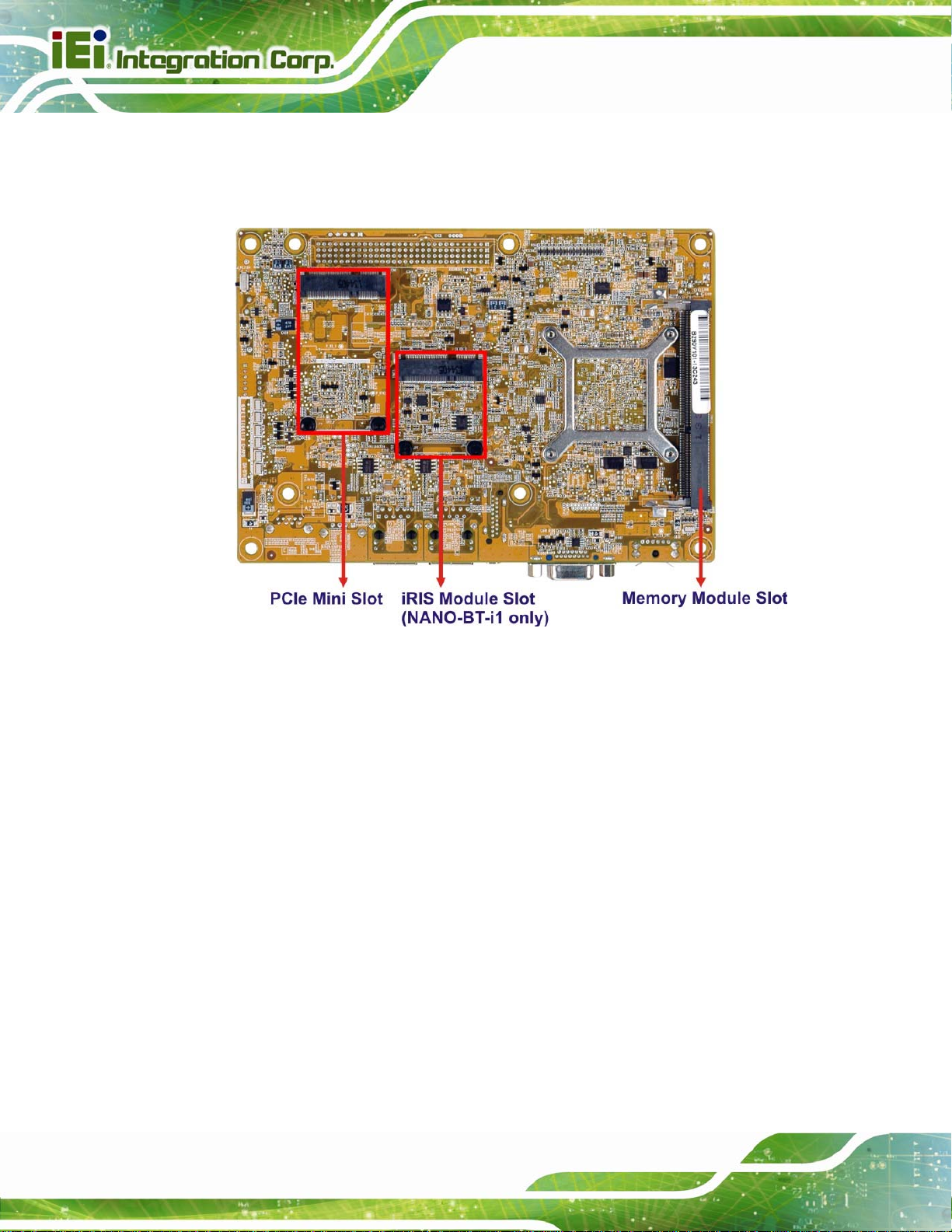
3.1.1 NANO-BT Layout
The figures below show all the connectors and jumpers.
NANO-BT EPIC SBC
*CN1 is only available in E38xx models.
Figure 3-1: Connectors and Jumpers (Front Side)
Page 18
Page 33
NANO-BT EPIC SBC
*IPMI1 is only available in NANO-BT-i1 models.
Figure 3-2: Connectors and Jumpers (Solder Side)
3.1.2 Peripheral Interface Connectors
The table below lists all the connectors on the board.
Connector Type Label
12 V DC input connector 4-pin connector CN10
Audio connector 10-pin header AUDIO1
Battery connector 2-pin wafer BAT1
Backlight inverter connector 5-pin wafer INV1
Buzzer connector 2-pin wafer SP1
Chassis intrusion connector 2-pin header CHASSIS1
Page 19
Page 34

Connector Type Label
Digital I/O connector 10-pin header DIO1
Fan connector (CPU) 3-pin wafer CPU_FAN1
Fan connector (system) 3-pin wafer SYS_FAN1
Front panel connector 6-pin wafer CN11
iRIS module connector Half-size PCIe Mini slot IPMI1
IPMI LED connector 2-pin header ID_LED2
LAN1 LED connector 2-pin header JP8
LAN2 LED connector 2-pin header JP9
LVDS connector 30-pin crimp CN2
NANO-BT EPIC SBC
Memory card slot DIMM slot DIMM1
microSD card slot microSD slot CN1
PCI-104 slot PCI-104 slot PC104_PLUS1
PCIe Mini slot Full-size PCIe Mini CN8
Power button connector 2-pin wafer PWR_BTN1
Power button Push button PWR_SW1
Reset button connector 2-pin wafer RST_BTN1
SATA 3Gb/s drive connectors 7-pin SATA connector SATA1, SATA2
SATA power connectors (5 V) 2-pin wafer SATA_PWR1, SATA_PWR2
Serial ports, RS-232 10-pin header COM1, COM2, COM3
Serial port, RS-422/485 4-pin wafer COM4
SMBus connector 4-pin wafer CN5
SPI flash connector 6-pin header JSPI1
SPI flash connector (EC) 6-pin header JSPI2
Page 20
Page 35
NANO-BT EPIC SBC
Connector Type Label
USB 2.0 connector 8-pin header USB1
Table 3-1: Peripheral Interface Connectors
3.1.3 External Interface Panel Connectors
The table below lists the connectors on the external I/O panel.
Connector Type Label
Ethernet ports RJ-45 LAN1, LAN2
HDMI connector HDMI CN12
Keyboard/Mouse connector PS/2 PT1
USB 2.0 connector USB 2.0 CN6
USB 3.0 connector USB 3.0 CN7
VGA connector 15-pin female VGA1
Table 3-2: Rear Panel Connectors
Page 21
Page 36

3.2 Internal Peripheral Connectors
The section describes all of the connectors on the NANO-BT.
3.2.1 +12 V Power Connector
CN Label: CN10
NANO-BT EPIC SBC
CN Type:
CN Location:
CN Pinouts:
The +12 V power input connector provides power to the system.
4-pin Molex power connector, p=4.2 mm
See Figure 3-3
See Table 3-3
Page 22
Figure 3-3: CPU Power Connector Location
PIN NO. DESCRIPTION
1 GND
2 GND
3 +12 V
4 +12 V
Table 3-3: CPU Power Connector Pinouts
Page 37

NANO-BT EPIC SBC
3.2.2 Audio Connector
CN Label: AUDIO1
CN Type:
CN Location:
CN Pinou
This
ts:
connector connects to speakers, a microphone and an audio input.
10-pin header, p=2.0 mm
See Figure 3-4
See Table 3-4
Figure 3-4: Audio Connector Location
Pin Description Pin Description
1 LINE_OUTR 2 LINEIN_R
3 ANALOG_GND 4 ANALOG_GND
5 LINE_OUTL 6 LINEIN_L
7 ANALOG_GND 8 ANALOG_GND
9 MICIN1 10 MICIN2
Table 3-4: Audio Connector Pinouts
Page 23
Page 38

3.2.3 Battery Connector
CAUTION:
Risk of explosion if battery is replaced by an incorrect type. Only
certified engineers should replace the on-board battery.
Dispose of used batteries according to instructions and local
regulations.
CN Label: BAT1
NANO-BT EPIC SBC
CN Type:
CN Location:
CN Pinou
A system battery is placed in the battery holder. The b
clock to retain the time when power is turned off.
Figure 3-5: Battery Connector Location
ts:
2-pin wafer, p=1.25 mm
See Figure 3-5
See Table 3-5
attery provides power to the system
Pin Description
Page 24
1 VBATT
2 GND
Table 3-5: Battery Connector Pinouts
Page 39
NANO-BT EPIC SBC
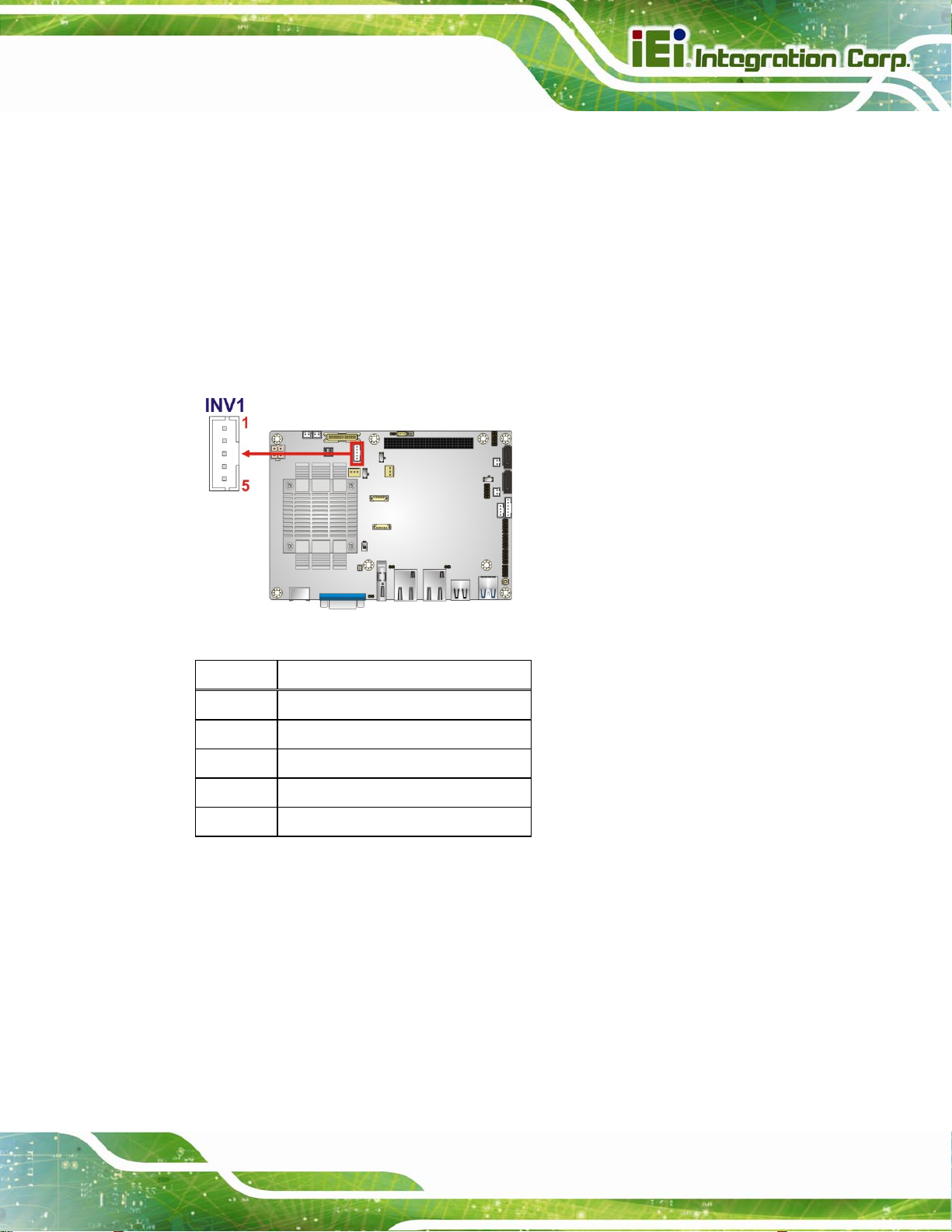
3.2.4 Backlight Inverter Connector
CN Label: INV1
CN Type:
CN Location:
CN Pinouts:
5-pin wafer, p=2.0 mm
5Figure 3-6
See
5Table 3-6
See
The backlight inverter connector provides power to an LCD panel.
Figure 3-6: Backlight Inverter Connector Location
Pin Description
1 BRIGHTNESS2
2 GND
3 VCC
4 GND
5 ENABKL2
Table 3-6: Backlight Inverter Connector Pinouts
Page 25
Page 40
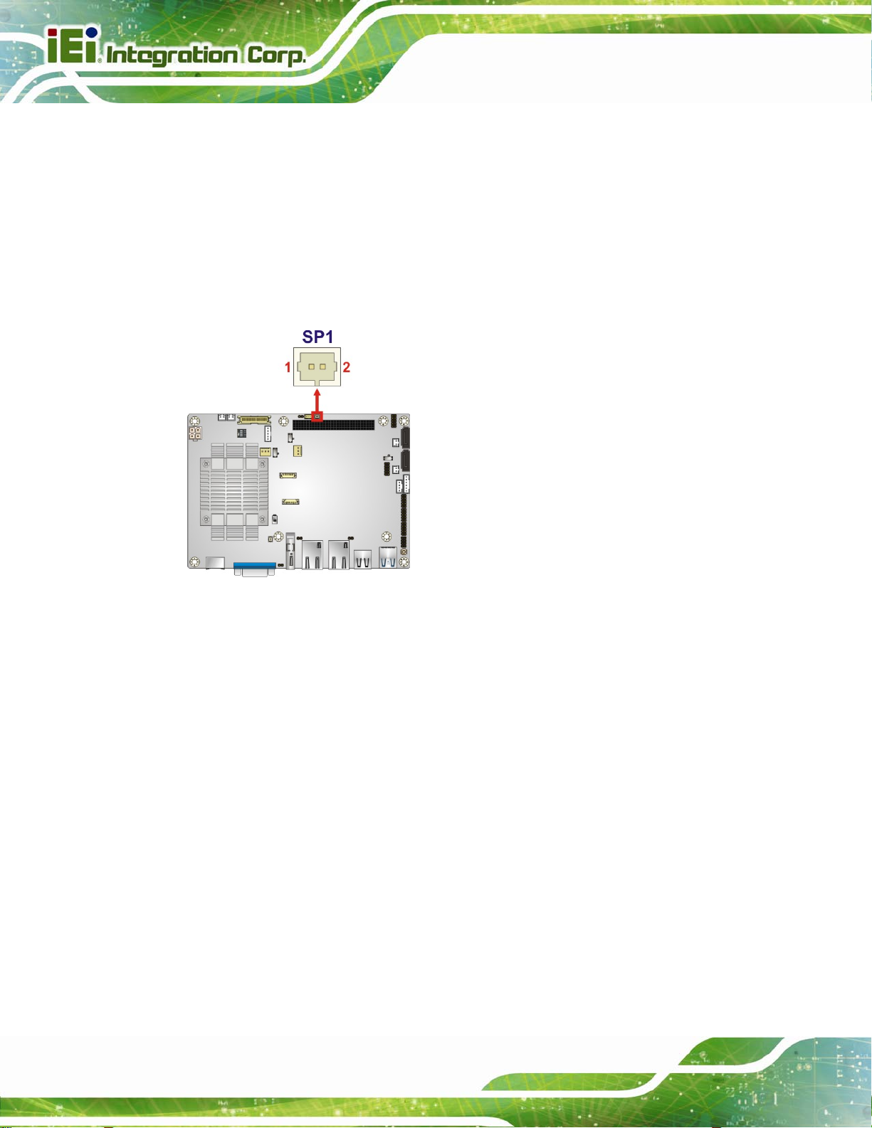
3.2.5 Buzzer Connector
CN Label: SP1
NANO-BT EPIC SBC
CN Type:
CN Location:
The co
nnector is connected to a buzzer.
Figure 3-7: Buzzer Connector Location
2-pin wafer, p=1.25 mm
See Figure 3-7
Page 26
Page 41
NANO-BT EPIC SBC
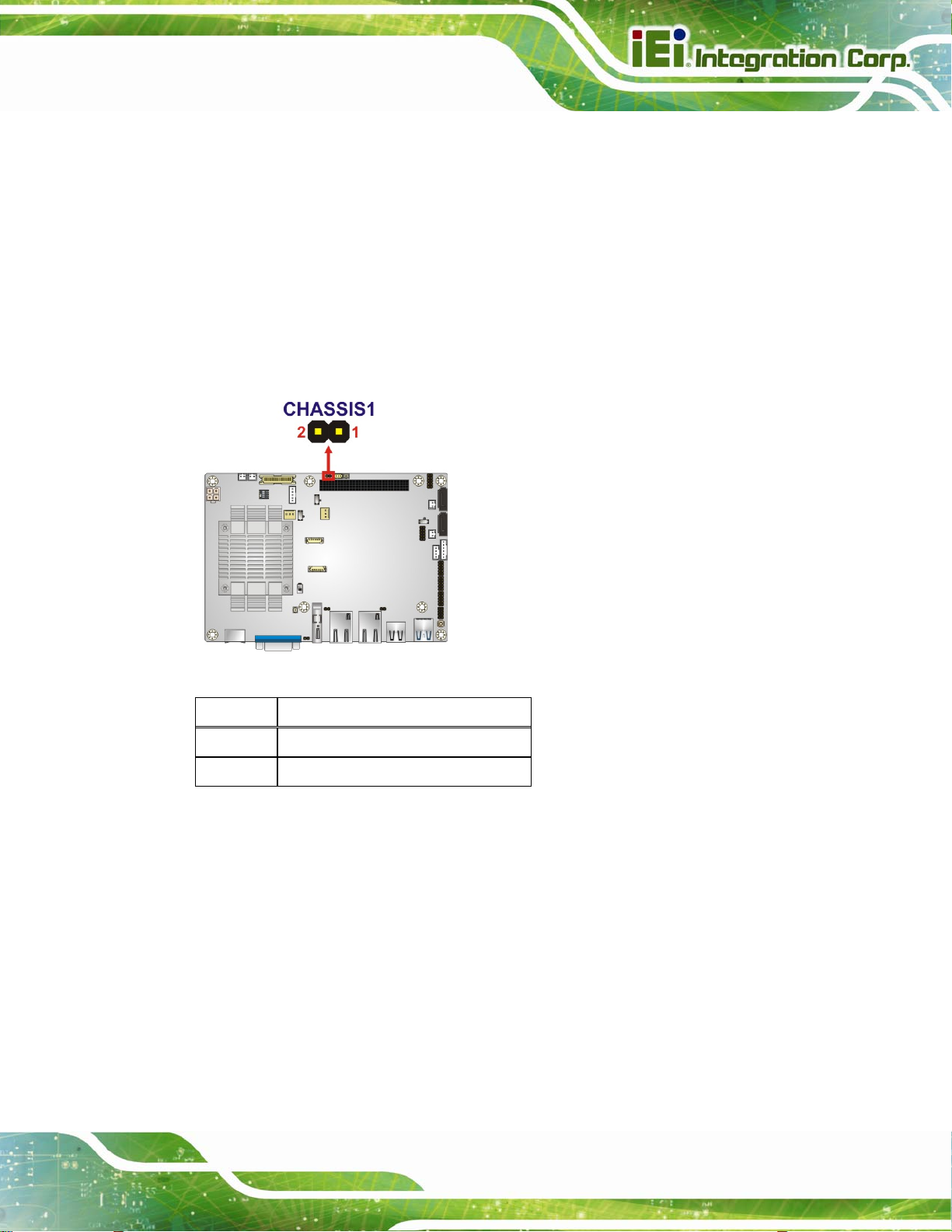
3.2.6 Chassis Intrusion Connector
CN Label: CHASSIS1
CN Type:
CN Location:
CN Pinouts:
The cha
ssis intrusion connector is for a chassis intrusion detection sensor or switch that
2-pin header, , p=2.0 mm
5Figure 3-8
See
See Table 3-7
detects if a chassis component is removed or replaced.
Figure 3-8: Chassis Intrusion Connector Location
Pin Description
1 +V3.3A_EC
2 CHASSIS_EC
Table 3-7: Chassis Intrusion Connector Pinouts
Page 27
Page 42

3.2.7 Digital I/O Connector
CN Label: DIO1
NANO-BT EPIC SBC
CN Type:
CN Location:
CN Pinouts:
10-pin header, p=2.0 mm
See Figure 3-9
See Table 3-8
The digital I/O connector provides programmable input and output for external devices.
The digital I/O provides 4-bit output and 4-bit input.
Figure 3-9: Digital I/O Connector Location
PIN NO. DESCRIPTION PIN NO. DESCRIPTION
Page 28
1 GND 2 +5V
3 DOUT3 4 DOUT2
5 DOUT1 6 DOUT0
7 DIN3 8 DIN2
9 DIN1 10 DIN0
Table 3-8: Digital I/O Connector Pinouts
Page 43
NANO-BT EPIC SBC
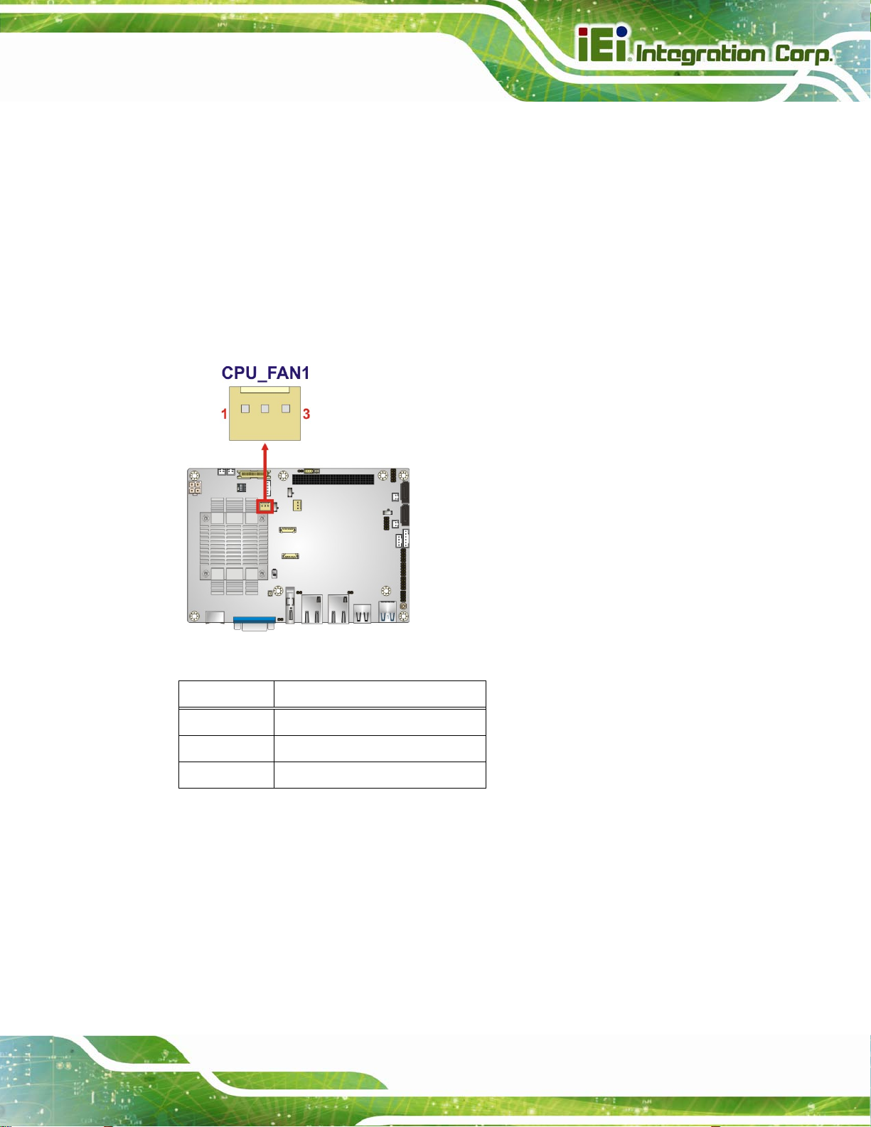
3.2.8 Fan Connector (CPU)
CN Label: CPU_FAN1
CN Type:
CN Location:
CN Pinouts:
The fan connector attaches to a CPU cooling fan.
3-pin wafer, p=2.54 mm
See Figure 3-10
See Table 3-9
Figure 3-10: CPU Fan Connector Location
PIN NO. DESCRIPTION
1 FAN_IN
2 VCC (+12 V)
3 GND
Table 3-9: CPU Fan Connector Pinouts
Page 29
Page 44

3.2.9 Fan Connector (System)
CN Label: SYS_FAN1
NANO-BT EPIC SBC
CN Type:
CN Location:
CN Pinouts:
Each fan connector attaches to a system cooling fan.
3-pin wafer, p=2.54 mm
See Figure 3-11
See Table 3-10
Page 30
Figure 3-11: System Fan Connector Location
PIN NO. DESCRIPTION
1 FAN_IN
2 VCC (+12 V)
3 GND
Table 3-10: System Fan Connector Pinouts
Page 45

NANO-BT EPIC SBC
3.2.10 Front Panel Connector
CN Label: CN11
CN Type:
CN Location:
CN Pinouts:
The front panel connector connects to the indicator LEDs on the computer's front panel.
Figure 3-12: Front Panel Connector Location
6-pin wafer, p=2.0 mm
See Figure 3-12
See Table 3-11
PIN DESCRIPTION PIN DESCRIPTION
1 VCC 4 PWR_LED2 GND 5 HDD_LED+
3 PWR_LED+ 6 HDD_LED-
Table 3-11: Front Panel Connector Pinouts
Page 31
Page 46

3.2.11 IPMI LED Connector
CN Label: ID_LED2
NANO-BT EPIC SBC
CN Type:
CN Location:
CN Pinou
The IPMI LED co
Figure 3-13: IPMI LED Connector Location
ts:
2-pin header, p=2.0 mm
See Figure 3-13
See Table 3-12
nnector is used to connect to the IPMI LED indicator on the chassis.
Page 32
Pin Description
1 ID_LED+
2 ID_LED-
Table 3-12: IPMI LED Connector Pinouts
Page 47

NANO-BT EPIC SBC
3.2.12 iRIS Module Slot (NANO-BT-i1 Models Only)
CN Label: IPMI1
CN Type:
CN Location:
The iRIS module slot is used to install the IEI iRIS-1010 IPMI 2.0 module. This slot is only
available in NANO-BT-i1 models.
Half-size PCIe Mini slot
5Figure 3-14
See
WARNING:
The iRIS module slot is designed to install the IEI iRIS-1010 IPMI 2.0
module only. DO NOT install other modules into the iRIS module slot.
Doing so may cause damage to the NANO-BT.
Figure 3-14: iRIS Module Slot Location
Page 33
Page 48
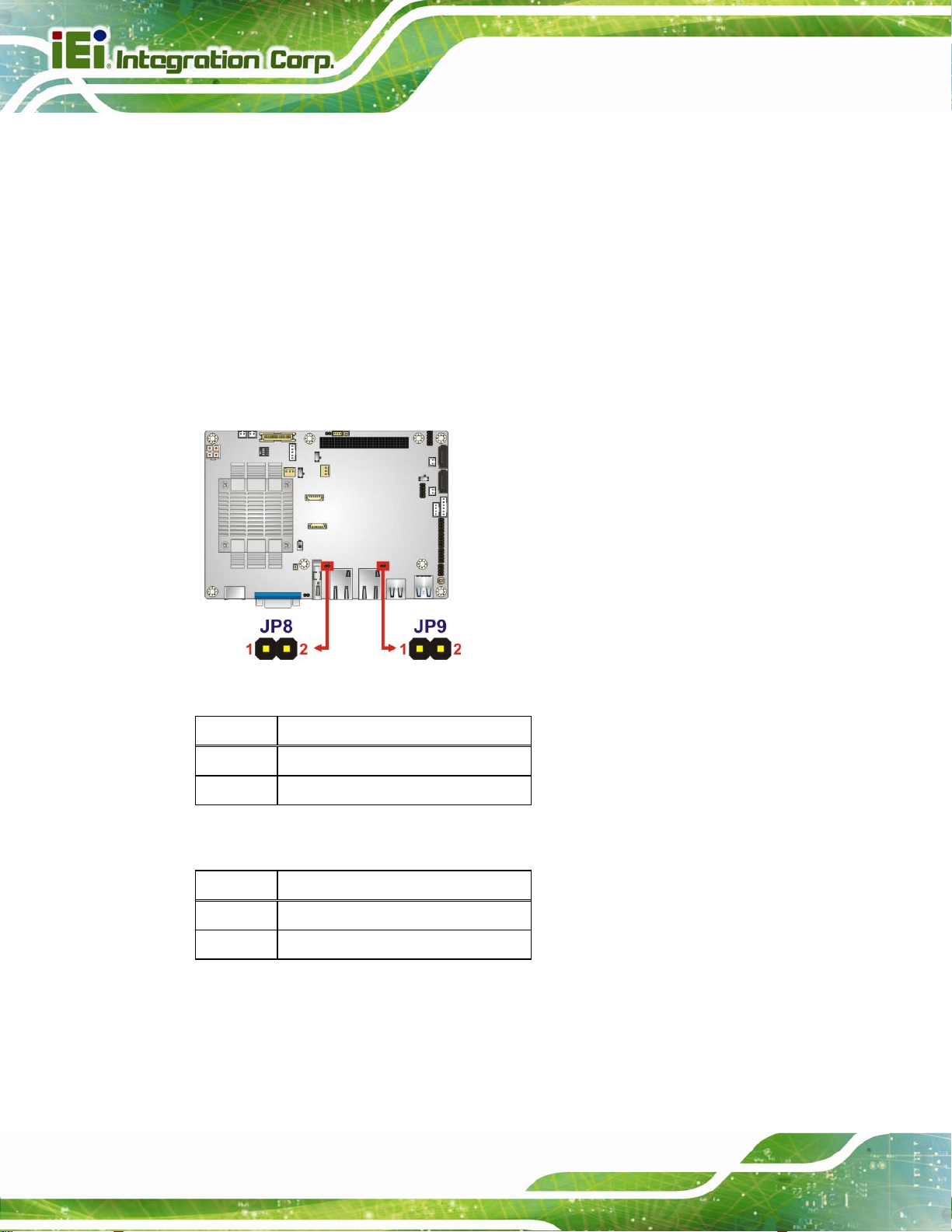
3.2.13 LAN LED Connectors
CN Label: JP8, JP9
NANO-BT EPIC SBC
CN Type:
CN Location:
CN Pinouts:
2-pin header, p=2.0 mm
5Figure 3-15
See
5Table 3-13 and Table 3-14
See
The LAN LED connectors are used to connect to the LAN LED indicators on the chassis to
indicate users the link activities of the two LAN ports.
Figure 3-15: LAN LED Connector Locations
Pin Description
1 VCC
2 L1_LINK_ACT-
Table 3-13: LAN1 LED Connector (JP8) Pinouts
Pin Description
1 VCC
2 L2_LINK_ACT-
Table 3-14: LAN2 LED Connector (JP9) Pinouts
Page 34
Page 49

NANO-BT EPIC SBC
3.2.14 LVDS Connector
CN Label: CN2
CN Type:
CN Location:
CN Pinou
The LVDS
ts:
connector is for an LCD panel connected to the board.
30-pin crimp, p=1.25 mm
See Figure 3-16
See Table 3-15
Figure 3-16: LVDS Connector Location
Pin Description Pin Description
1 GND 2 GND
3 LVDS_A_TX0-P 4 LVDS_ A_TX0-N
5 LVDS_ A_TX1-P 6 LVDS_ A_TX1-N
7 LVDS_ A_TX2-P 8 LVDS_ A_TX2-N
9 LVDS_ A_TXCLK-P 10 LVDS_ A_TXCLK-N
11 LVDS_ A_TX3-P 12 LVDS_ A_TX3-N
13 GND 14 GND
15 LVDS_B_TX0-P 16 LVDS_ B_TX0-N
17 LVDS_ B_TX1-P 18 LVDS_ B_TX1-N
19 LVDS_ B_TX2-P 20 LVDS_ B_TX2-N
21 LVDS_ B_TXCLK-P 22 LVDS_ B_TXCLK-N
Page 35
Page 50
Pin Description Pin Description
23 LVDS_ B_TX3-P 24 LVDS_ B_TX3-N
25 GND 26 GND
27 +LCD VCC 28 +LCD VCC
29 +LCD VCC 30 +LCD VCC
Table 3-15: LVDS Connector Pinouts
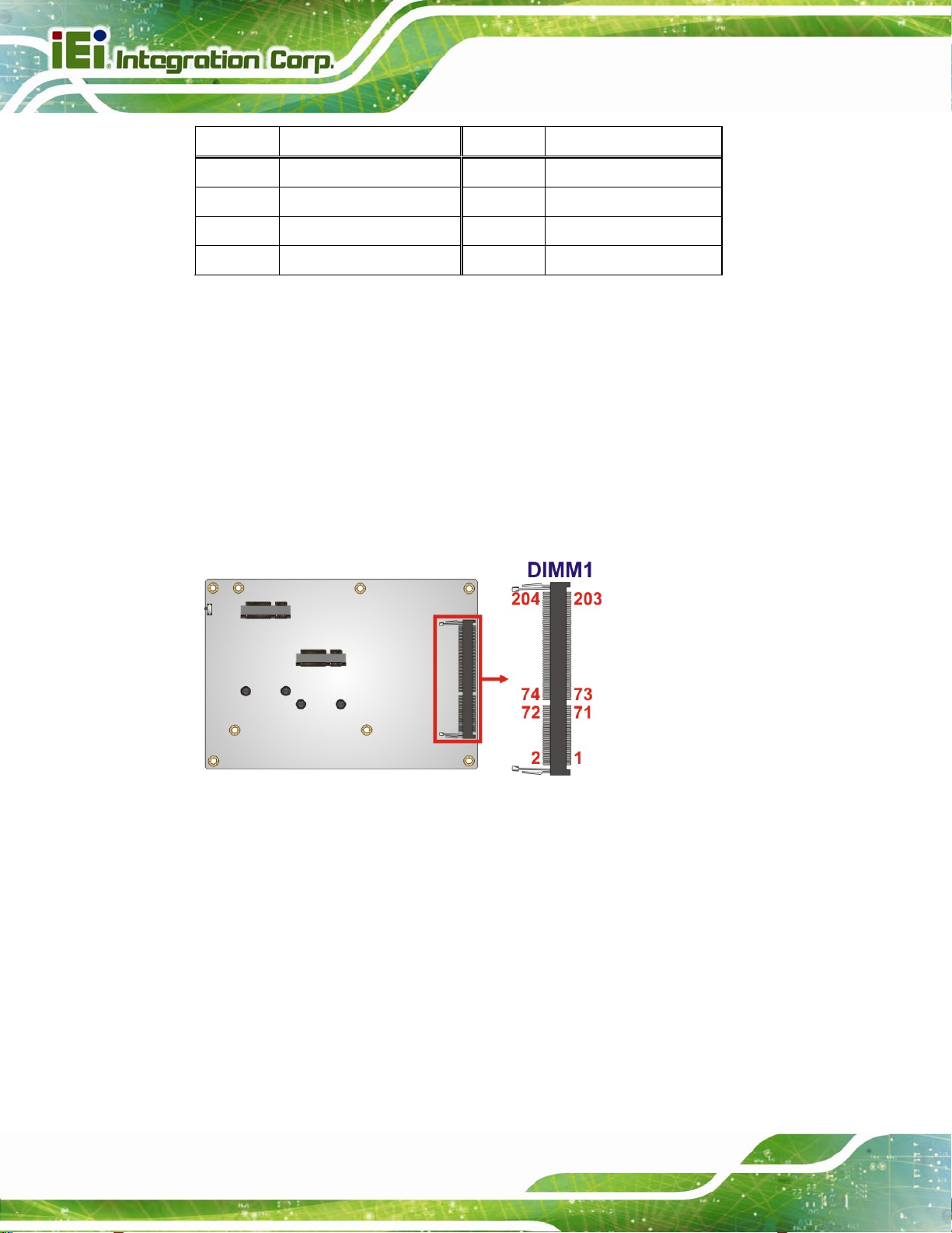
3.2.15 Memory Card Slot
CN Label: DIMM1
NANO-BT EPIC SBC
CN Type:
CN Location:
DDR3 SO-DIMM slot
See 5Figure 3-17
The SO-DIMM slot is for installing DDR3 Low Voltage SO-DIMM memory modules.
Figure 3-17: Memory Card Slot Location
Page 36
Page 51

NANO-BT EPIC SBC
3.2.16 microSD Card Slot (E38xx Models Only)
CN Label: CN1
CN Type:
CN Location:
The microSD card slot is used to install microSD card. This slot is only available in E38xx
models.
Figure 3-18: microSD Card Slot Location
microSD slot
5Figure 3-14
See
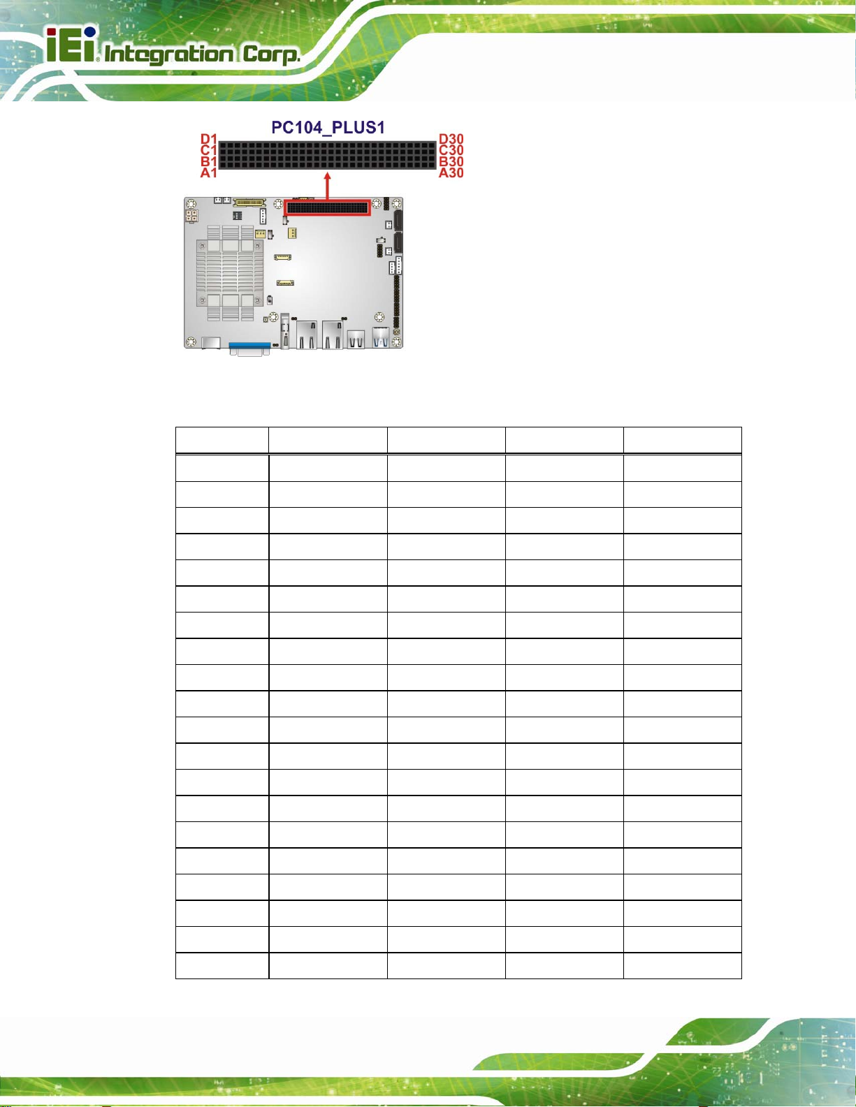
3.2.17 PCI-104 Connector
CN Label: PC104_PLUS1
CN Type:
CN Location:
CN Pinou
The PCI-104
ts:
PCI-104 connector
See Figure 3-19
See Table 3-16
connector is for installing a PCI-104 expansion card.
Page 37
Page 52
NANO-BT EPIC SBC
Figure 3-19: PCI-104 Connector Location
Pin Row A Row B Row C Row D
1 GND/5 V TBD1 5 V AD00
2 VI/O1 AD02 AD01 +5 V
3 AD05 GND AD04 AD03
4 C/BE0# AD07 GND AD06
5 GND AD09 AD08 GND
6 AD11 VI/O2 AD10 M66EN
7 AD14 AD13 GND AD12
8 +3.3 V C/BE1# AD15 +3.3 V
9 SERR# GND SB0# PAR
10 GND PERR# +3.3 V SDONE
11 STOP# +3.3 V LOCK# GND
12 +3.3 V TRDY# GND DEVSEL#
13 FRAME# GND IRDY# +3.3 V
14 GND AD16 +3.3 V C/BE2#
15 AD18 +3.3 V AD17 GND
16 AD21 AD20 GND AD19
17 +3.3 V AD23 AD22 +3.3 V
Page 38
18 IDSEL0 GND IDSEL1 IDSEL2
19 AD24 C/BE3# VI/O1 IDSEL3
20 GND AD26 AD25 GND
Page 53

NANO-BT EPIC SBC
Pin Row A Row B Row C Row D
21 AD29 +5 V AD28 AD27
22 +5 V AD30 GND AD31
23 REQ0# GND REQ1# VI/O2
24 GND REQ2# +5 V GNT0#
25 GNT1# VI/O3 GNT2# GND
26 +5 V CLK0 GND CLK1
27 CLK2 +5 V CLK3 GND
28 GND INTD# +5 V RST#
29 +12 V INTA# INTB# INTC#
30 -12 V TBD2 TBD GND/3.3 V
Table 3-16: PCI-104 Connector Pinouts
3.2.18 PCIe Mini Card Slot
CN Label: CN8
CN Type:
CN Location:
CN Pinouts:
The PCIe Mini card
PCIe Mini card slot
5Figure 3-20
See
See Table 3-17
slot is for installing PCIe Mini expansion cards, such as mSATA
modules or Wi-Fi modules.
Figure 3-20: PCIe Mini Card Slot Location
Page 39
Page 54

Pin Description Pin Description
1 PCIE_WAKE# 2 VCC3
3 N/C 4 GND
5 N/C 6 1.5 V
7 VCC3 8 N/C
9 GND 10 N/C
11 CLK- 12 N/C
13 CLK+ 14 N/C
15 GND 16 N/C
17 BUF_PLT_RST# 18 GND
19 N/C 20 VCC3
21 GND 22 BUF_PLT_RST#
23 PCIE_RX4DN_M 24 VCC3
25 PCIE_RX4DP_M 26 GND
NANO-BT EPIC SBC
27 GND 28 1.5 V
29 GND 30 SMBCLK
31 PCIE_TX4DN_CM 32 SMBDATA
33 PCIE_TX4DP_CM 34 GND
35 GND 36 USBD337 GND 38 USBD3+
39 VCC3 40 GND
41 VCC3 42 N/C
43 GND 44 RF_LINK#
45 N/C 46 BLUELED#
47 N/C 48 1.5 V
49 N/C 50 GND
51 M-SATADET 52 VCC3
Table 3-17: PCIe Mini Card Slot Pinouts
Page 40
Page 55
NANO-BT EPIC SBC
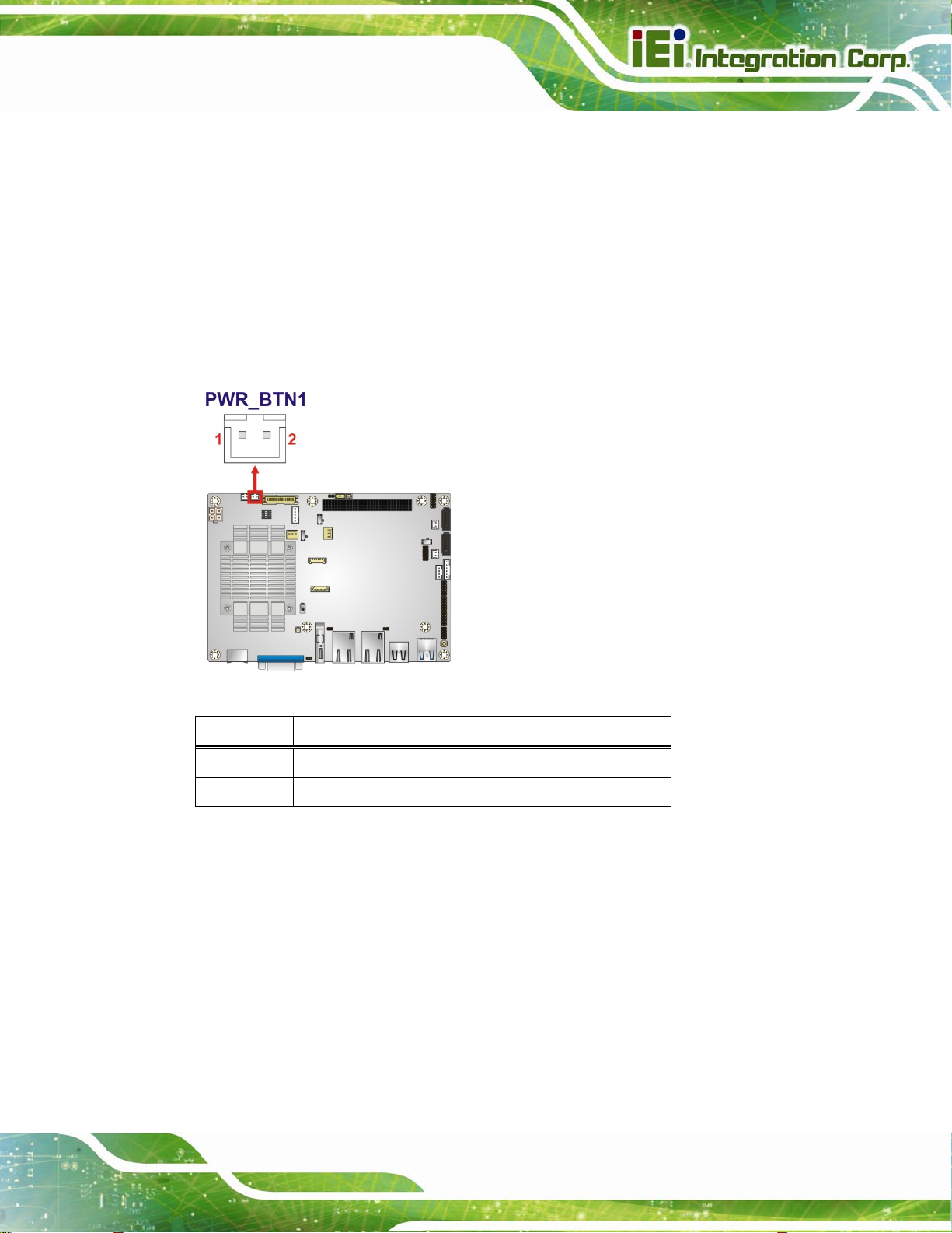
3.2.19 Power Button Connector
CN Label: PWR_BTN1
CN Type:
CN Location:
CN Pinou
The po
Figure 3-21: Power Button Location
ts:
wer button connector is connected to a power switch on the system chassis.
2-pin wafer, p=2.0 mm
See Figure 3-21
See Table 3-18
Pin Description
1 PWRBTN_SW#
2 GND
Table 3-18: Power Button Pinouts
3.2.20 Power Button
CN Label: PWR_SW1
CN Type:
CN Location:
The on
-board power button controls system power.
Push button
See Figure 3-22
Page 41
Page 56
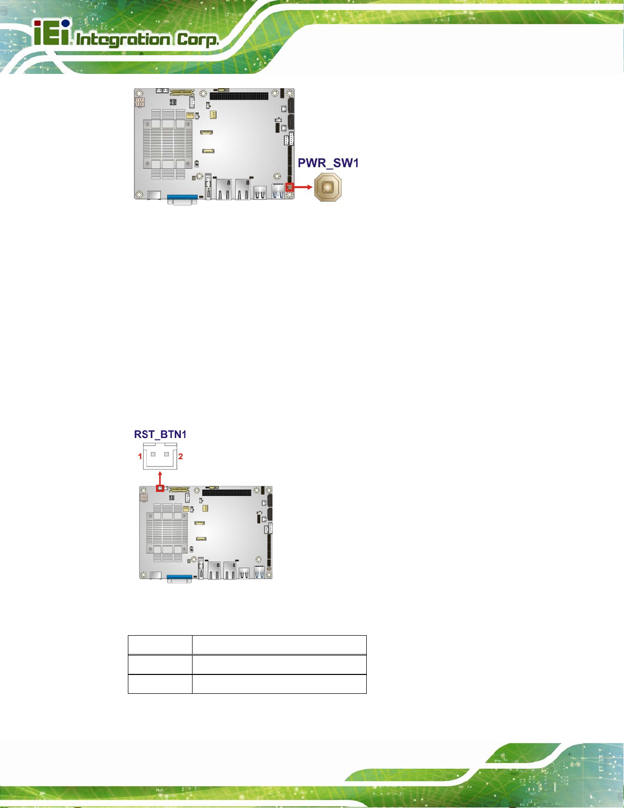
Figure 3-22: Power Button Location
3.2.21 Reset Button Connector
CN Label: RST_BTN1
NANO-BT EPIC SBC
CN Type:
CN Location:
CN Pinou
The re
Figure 3-23: Reset Button Connector Location
ts:
set button connector is connected to a reset switch on the system chassis.
2-pin wafer, p=2.0 mm
See Figure 3-23
See Table 3-19
Page 42
Pin Description
1 PM_SYSRST_R#
2 GND
Table 3-19: Reset Button Connector Pinouts
Page 57

NANO-BT EPIC SBC
3.2.22 SATA 3Gb/s Drive Connectors
CN Label: SATA1, SATA2
CN Type:
CN Location:
CN Pinouts:
7-pin SATA drive conn ectors
See Figure 3-24
See Table 3-20
The SATA drive connectors can be connected to SATA drives.
Figure 3-24: SATA 3Gb/s Drive Connector Locations
Pin Description
1 GND
2 SATA_TX+
3 SATA_TX4 GND
5 SATA_RX6 SATA_RX+
7 GND
Table 3-20: SATA 3Gb/s Drive Connector Pinouts
Page 43
Page 58

3.2.23 SATA Power Connectors
CN Label: SATA_PWR1, SATA_PWR2
NANO-BT EPIC SBC
CN Type:
CN Location:
CN Pinou
Use the SATA Power Con
Figure 3-25: SATA Power Connector Locations
ts:
2-pin wafer, p=2.0 mm
See Figure 3-25
See Table 3-21
nector to connect to SATA device power connections.
Page 44
Pin Description
1 +5VS
2 GND
Table 3-21: SATA Power Connector Pinouts
Page 59
NANO-BT EPIC SBC
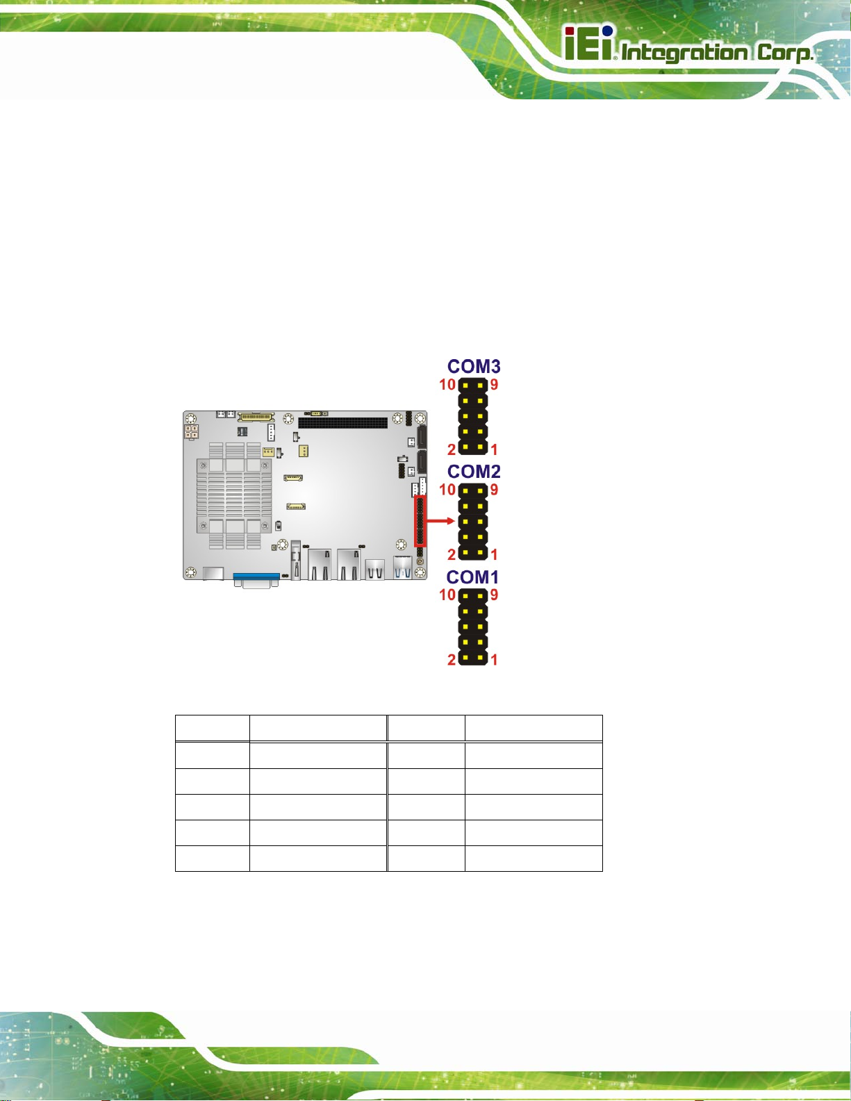
3.2.24 Serial Port Connectors, RS-232
CN Label: COM1, COM2, COM3
CN Type:
CN Location:
CN Pinouts:
The connector provides RS-232 port connection.
10-pin header, p=2.0 mm
See Figure 3-26
See Table 3-22
Figure 3-26: RS-232 Serial Port Connector Locations
PIN NO. DESCRIPTION PIN NO. DESCRIPTION
1 DCD 2 DSR
3 SIN 4 RTS
5 SOUT 6 CTS
7 DTR 8 RI
9 GND 10 GND
Table 3-22: RS-232 Serial Port Connector Pinouts
Page 45
Page 60

3.2.25 Serial Port Connector, RS-422/485
CN Label: COM4
NANO-BT EPIC SBC
CN Type:
CN Location:
CN Pinouts:
Used for RS-422/485 communications.
Figure 3-27: RS-422/485 Connector Location
4-pin wafer, p=2.0 mm
See Figure 3-27
See Table 3-23
PIN NO. DESCRIPTION
Page 46
1 RXD4222 RXD422+
3 TXD422+/TXD485+
4 TXD422-/TXD485-
Table 3-23: RS-422/485 Connector Pinouts
Use the optional RS-422/485 cable to connect to a serial device. The pinouts of the
D-sub 9 connector are listed below.
Page 61

NANO-BT EPIC SBC
RS-422 Pinouts RS-485 Pinouts
Table 3-24: RS-422/485 Pinouts of D-sub 9 Connector
3.2.26 SMBus Connector
CN Label: CN5
CN Type:
4-pin wafer, p=1.25 mm
CN Location: See Figure 3-28
CN Pinouts: See Table 3-25
The SMBus (System Management Bus) connector provides low-speed system
management communications.
Figure 3-28: SMBus Connector Location
PIN DESCRIPTION
1 GND
2 SMB_DATA
Page 47
Page 62

PIN DESCRIPTION
3 SMB_CLK
4 +5 V
Table 3-25: SMBus Connector Pinouts
3.2.27 SPI Flash Connector
CN Label: JSPI1
NANO-BT EPIC SBC
CN Type:
CN Location:
CN Pinouts:
6-pin wafer, p=1.25 mm
See Figure 3-29
See Table 3-26
The SPI flash connector is used to flash the SPI ROM.
Page 48
Figure 3-29: SPI Flash Connector Location
PIN NO. DESCRIPTION PIN NO. DESCRIPTION
1 +1.8 VA 4 SPI_CLK_SW
2 SPI_CS 5 SPI_SI_SW
3 SPI_SO_SW 6 GND
Table 3-26: SPI Flash Connector Pinouts
Page 63

NANO-BT EPIC SBC
3.2.28 SPI Flash Connector, EC
CN Label: JSPI2
CN Type:
CN Location:
CN Pinouts:
The SPI flash connector is used to flash the EC ROM.
6-pin wafer, p=1.25 mm
See Figure 3-30
See Table 3-27
Figure 3-30: SPI EC Flash Connector Location
PIN NO. DESCRIPTION PIN NO. DESCRIPTION
1 +3.3 A 4 SPI_CLK_SW_EC
2 SPI_CS#0_CN_EC 5 SPI_SI_SW_EC
3 SPI_SO_SW_EC 6 GND
Table 3-27: SPI EC Flash Connector Pinouts
Page 49
Page 64
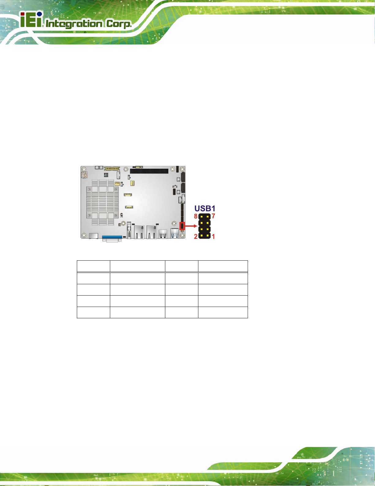
3.2.29 USB 2.0 Connector
CN Label: USB1
NANO-BT EPIC SBC
CN Type:
CN Location:
CN Pinouts:
The USB 2.0 connector connects to USB 2.0 devices. Each pin header provides two USB
2.0 ports.
Figure 3-31: USB 2.0 Connector Location
8-pin header , p=2.0 mm
See Figure 3-31
See Table 3-28
PIN NO. DESCRIPTION PIN NO. DESCRIPTION
Page 50
1 +VCC_USB45 2 GND
3 DATA4- 4 DATA5+
5 DATA4+ 6 DATA57 GND 8 +VCC_USB45
Table 3-28: USB 2.0 Connector Pinouts
Page 65

NANO-BT EPIC SBC
3.3 External Peripheral Interface Connector Panel
The figure below shows the external peripheral interface connector (EPIC) panel. The
EPIC panel consists of the following:
Figure 3-32: External Peripheral Interface Connector
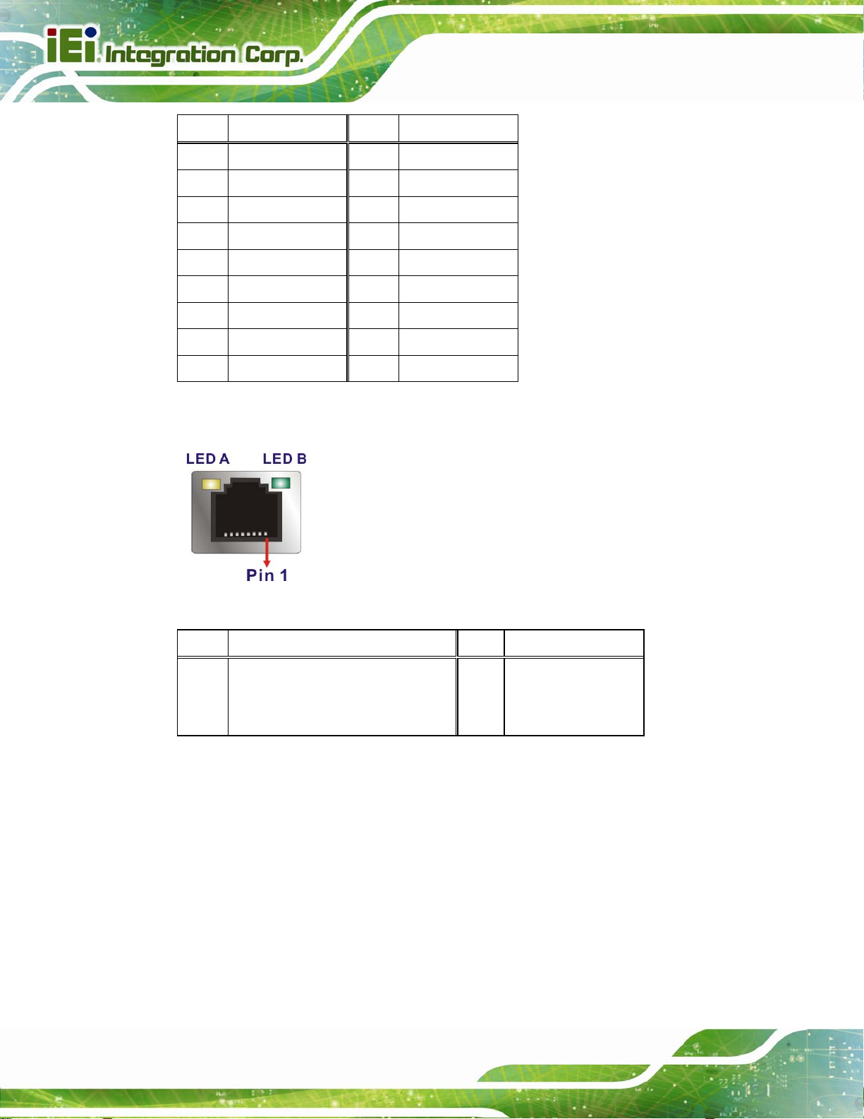
3.3.1 Ethernet Connectors
CN Label: LAN1, LAN2
CN Type:
CN Location:
CN Pinou
ts:
A 10/100/10
RJ-45
See Figure 3-32
See Table 3-29 and Table 3-30
00 Mb/s connection can be made to a Local Area Network. The LAN1
Ethernet connector supports IPMI 2.0.
Pin Description Pin Description
G1 IO_GND R2 TRD1N0
G2 IO_GND R3 TRD1P1
L1 L1_100- R4 TRD1N1
L2 L1_1000- R5 N95788738
L3 L1_LINK_ACT- R6 N95788617
L4 N100494685 R7 TRD1P2
N1 NC R8 TRD1N2
N2 NC R9 TRD1P3
R1 TRD1P0 R10 TRD1N3
Table 3-29: LAN1 Ethernet Connector Pinouts
Page 51
Page 66
Pin Description Pin Description
G1 IO_GND_1 R2 TRD2N0
G2 IO_GND_1 R3 TRD2P1
L1 L2_100- R4 TRD2N1
L2 L2_1000- R5 N95934519
L3 L2_LINK_ACT- R6 N95934513
L4 N100495197 R7 TRD2P2
N1 NC R8 TRD2N2
N2 NC R9 TRD2P3
R1 TRD2P0 R10 TRD2N3
NANO-BT EPIC SBC
Table 3-30: LAN2 Ethernet Connector Pinouts
Figure 3-33: Ethernet Connector
LED Description LED Description
A on: linked
blinking: data is being sent/received
Table 3-31: Connector LEDs
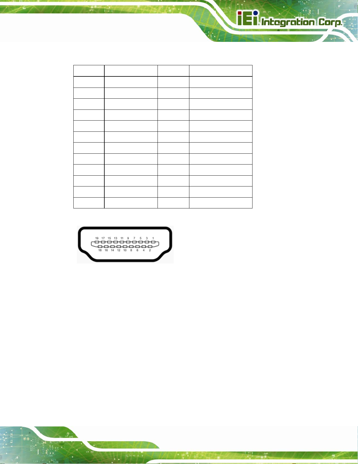
3.3.2 HDMI Connector
CN Label: CN12
CN Type:
CN Location:
CN Pinou
ts:
B off: 10 Mb/s
green: 100 Mb/s
orange: 1000 Mb/s
23-pin HDMI port
See Figure 3-32
See Table 3-32
Page 52
Page 67
NANO-BT EPIC SBC
The HDMI connector can connect to an HDMI device.
Pin Description Pin Description
1 HDMI_DATA2 2 GND
3 HDMI_DATA2# 4 HDMI_DATA1
5 GND 6 HDMI_DATA1#
7 HDMI_DATA0 8 GND
9 HDMI_DATA0# 10 HDMI_CLK
11 GND 12 HDMI_CLK#
13 N/C 14 N/C
15 HDMI_SCL 16 HDMI_SDA
17 GND 18 +5V
19 HDMI_HPD 20 HDMI_GND
21 HDMI_GND 22 HDMI_GND
23 HDMI_GND
Table 3-32: HDMI Connector Pinouts
Figure 3-34: HDMI Connector
3.3.3 Keyboard/Mouse Connector
CN Label: PT1
CN Type:
CN Location:
CN Pinou
ts:
PS/2
See Figure 3-32
See Table 3-33
The keyb
oard and mouse connector is a standard PS/2 connector.
Page 53
Page 68

NANO-BT EPIC SBC
Figure 3-35: PS/2 Pinout and Configuration
Pin Description
1 KB DATA
2 MS DATA
3 GND
4 VCC
5 KB CLOCK
6 MS CLOCK
Table 3-33: Keyboard Connector Pinouts
3.3.4 USB 2.0 Connector
CN Label: CN6
CN Type:
CN Location:
CN Pinou
ts:
The USB con
Pin Description Pin Description
1 USB3_PWR1 4 GND
2 DATA1_N 5 USB_GND
USB 2.0 port
See Figure 3-32
See Table 3-34
nector can be connected to a USB device.
Page 54
3 DATA1_P 6 USB_GND
Table 3-34: USB 2.0 Port Pinouts
Page 69

NANO-BT EPIC SBC
3.3.5 USB 3.0 Connector
CN Label: CN7
CN Type:
CN Location:
CN Pinou
ts:
The USB con
Pin Description Pin Description
1 USB3_PWR1 6 USB3P0_RXDP1
2 USB2P0_DM1_L 7 USB_GND
3 USB2P0_DP1_L 8 USB3P0_TXDN1_C
4 GND 9 USB3P0_TXDP1_C
5 USB3P0_RXDN1
USB 3.0 port
See Figure 3-32
See Table 3-35
nector can be connected to a USB device.
Table 3-35: USB 3.0 Port Pinouts
3.3.6 VGA Connector
CN Label: VGA1
CN Type:
CN Location:
CN Pinouts:
15-pin Female
See Figure 3-32
See Table 3-36 and Figure 3-36
Both VGA connectors can be connected to monitors that accept standard VGA input for
easy dual display setup. The VGA connectors support up to 1920 x 1200 resolutions.
PIN DESCRIPTION PIN DESCRIPTION
V1 RED V2 GREEN
V3 BLUE V4 NC
V5 GND V6 GND
V7 GND V8 GND
V9 VCC V10 GND
Page 55
Page 70

PIN DESCRIPTION PIN DESCRIPTION
V11 NC V12 DDCDA
V13 HSYNC V14 VSYNC
V15 DDCCLK
NANO-BT EPIC SBC
Table 3-36: VGA Connector Pinouts
Figure 3-36: VGA Connector
Page 56
Page 71

NANO-BT EPIC SBC
Chapter
4
4 Installation
Page 57
Page 72
4.1 Anti-static Precautions
WARNING:
Failure to take ESD precautions during the installation of the NANO-BT
may result in permanent damage to the NANO-BT and severe injury to
the user.
Electrostatic discharge (ESD) can cause serious damage to electronic components,
including the NANO-BT. Dry climates are especially susceptible to ESD. It is therefore
critical that whenever the NANO-BT or any other electrical component is handled, the
following anti-static precautions are strictly adhered to.
Wear an anti-static wristband: - Wearing a simple anti-static wristband can
NANO-BT EPIC SBC
help to prevent ESD from damaging the board.
Self-grounding:- Before handling the board touch any grounded conducting
material. During the time the board is handled, frequently touch any
conducting materials that are connected to the ground.
Use an anti-static pad: When configuring the NANO-BT, place it on an
anti-static pad. This redu ces the possibility of ESD damaging the NANO-BT.
Only handle the edges of the PCB:-: When handling the PCB, hold the PCB
by the edges.
4.2 Installation Considerations
NOTE:
The following installation notices and installation considerations should
be read and understood before installation. All installation notices must
be strictly adhered to. Failing to adhere to these precautions may lead
Page 58
to severe damage and injury to the person performing the installation.
Page 73

NANO-BT EPIC SBC
WARNING:
The installation instructions described in this manual should be
carefully followed in order to prevent damage to the components and
injury to the user.
Before and during the installation please DO the following:
Read the user manual:
o The user manual provides a complete description of the NANO-BT
Wear an electrostatic discharge cuff (ESD):
o Electronic components are easily damaged by ESD. Wearing an ESD cuff
installation instructions and configuration options.
removes ESD from the body and helps prevent ESD damage.
Place the NANO-BT on an antistatic pad:
o When installing or configuring the motherboard, place it on an antistatic
pad. This helps to prevent potential ESD damage.
Turn all power to the NANO-BT off:
o When working with the NANO-BT, make sure that it is disconnected from
all power supplies and that no electricity is being fed into the system.
Before and during the installation of the NANO-BT DO NOT:
Remove any of the stickers on the PCB board. These stickers are required for
warranty validation.
Use the product before verifying all the cables and power connectors are
properly connected.
Allow screws to come in contact with the PCB circuit, connector pins, or its
components.
Page 59
Page 74

4.2.1 SO-DIMM Installation
To install an SO-DIMM, please follow the steps below and refer to Figure 4-1.
Figure 4-1: SO-DIMM Installation
Step 1: Locate the SO-DIMM socket on the solder side of the NANO-BT. Place the
board on an anti-static mat.
NANO-BT EPIC SBC
Step 2: Align the SO-DIMM with the socket. Align the notch on the memory with the
notch on the memory socket.
Step 3: Insert the SO-DIMM. Push the memory in at a 20º angle. (See Figure 4-1)
Step 4: Seat th
Figure 4-1)
e SO-DIMM. Gently push downwards and the arms clip into place. (See
4.2.2 iRIS-1010 Module Installation (Optional)
WARNING:
The iRIS module slot is designed to install the IEI iRIS-1010 IPMI 2.0
module only. DO NOT install other modules into the iRIS module slot.
Doing so may cause damage to the NANO-BT.
Page 60
To install the iRIS-1010 module, please follow the steps below and refer to Figure 4-2.
Page 75
NANO-BT EPIC SBC
Figure 4-2: iRIS-1010 Module Installation
Step 1: Locate the iRIS module slot on the solder side. See Figure 3-14.
Step 2: Insert into
with the notch on the connector . Slide the RIS-10 10 module into th e socket at an
angle of about 20º.
Step 3: Push down until the RIS-1010 module clips into place. Push the other end of
the RIS-1010 module down until it clips into place on the plastic connector.
the socket at an angle. Line up the notch on the RIS-1010 module
NOTE:
After installing the iRIS-1010 module, use LAN1 port to establish a
network connection. Please refer to Section 4.5 for IPMI
procedures.
setup
Page 61
Page 76

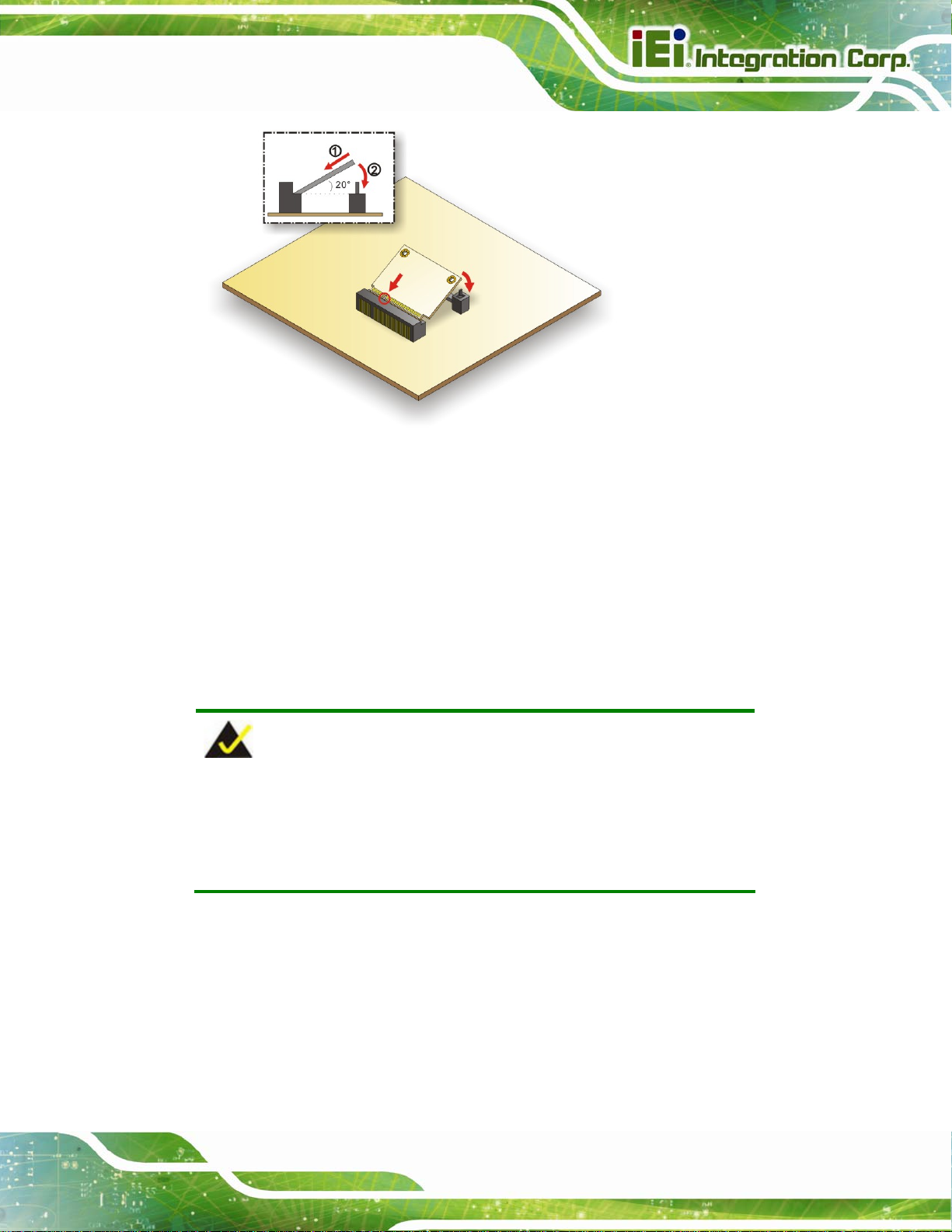
4.2.3 PCIe Mini Card Installation
To install the PCIe Mini card, please refer to the diagram and instructions below.
NANO-BT EPIC SBC
Figure 4-3: PCIe Mini Card Installation
Step 1: Insert into the socket at an angle. Line up the notch on the card with the notch
on the connector. Slide the PCIe Mini card into the socket at an angle of about
20º.
Step 2: Push down until the card clips into place. Push the other end of the card
down until it clips into place on the plastic connector.Step 0:
4.3 System Configuration
The NANO-BT is a jumperless single board computer. The system configuration is
controlled by buttons and switches. The system configuration must be performed before
installation.
4.3.1 AT/ATX Power Mode Setting
The AT and ATX power mode selection is made through the AT/ATX power mode switch
Page 62
which is shown in Figure 4-4.
Page 77

NANO-BT EPIC SBC
Figure 4-4: AT/ATX Power Mode Switch Location
4.3.2 Clear CMOS Button
To reset the BIOS, remove the on-board battery and press the clear CMOS button for
three seconds or more. The clear CMOS button location is shown in Figure 4-5.
Figure 4-5: Clear CMOS Button Location
Page 63
Page 78

4.3.3 LVDS Panel Resolution Selection
Use the SW1 DIP switch to select the resolution of the LCD panel connected to the LVDS
connector.
SW1 (4-3-2-1) Description
0000 800x600 18-bit (Default)
0001 1024x768 18-bit
0010 1024x768 24-bit
0011 1280x768 18-bit
0100 1280x800 18-bit
0101 1280x960 18-bit
0110 1280x1024 48-bit
0111 1366x768 18-bit
1000 1366x768 24-bit
NANO-BT EPIC SBC
1001 1440x900 48-bit
1010 1400x1050 48-bit
1011 1600x900 48-bit
1100 1680x1050 48-bit
1101 1600x1200 48-bit
1110 1920x1080 48-bit
1111 1920x1200 48-bit
*ON=0, OFF=1
Table 4-1: LVDS Panel Resolution Selection
Page 64
Page 79

NANO-BT EPIC SBC
Figure 4-6: LVDS Panel Resolution Selection Switch Location
4.3.4 LCD Voltage Selection
The LCD voltage selection switch sets the voltage of the po wer supplied to the L CD panel.
The LCD Voltage Selection settings are shown in Table 4-2.
Setting Description
A-B +3.3 V (Default)
B-C +5.0 V
Table 4-2: LCD Voltage Selection Switch Settings
Page 65
Page 80

Figure 4-7: LCD Voltage Selection Switch Location
NANO-BT EPIC SBC
4.3.5 mSATA/SATA Selection
Use the J_SATA1 switch to select whether to automatically detect mSATA devices.
Setting Description
A-B Automatically detect mSATA device (Default)
B-C Enable mSATA device
Table 4-3: mSATA/SATA Switch Settings
Page 66
Figure 4-8: mSATA/SATA Switch Location
Page 81
NANO-BT EPIC SBC
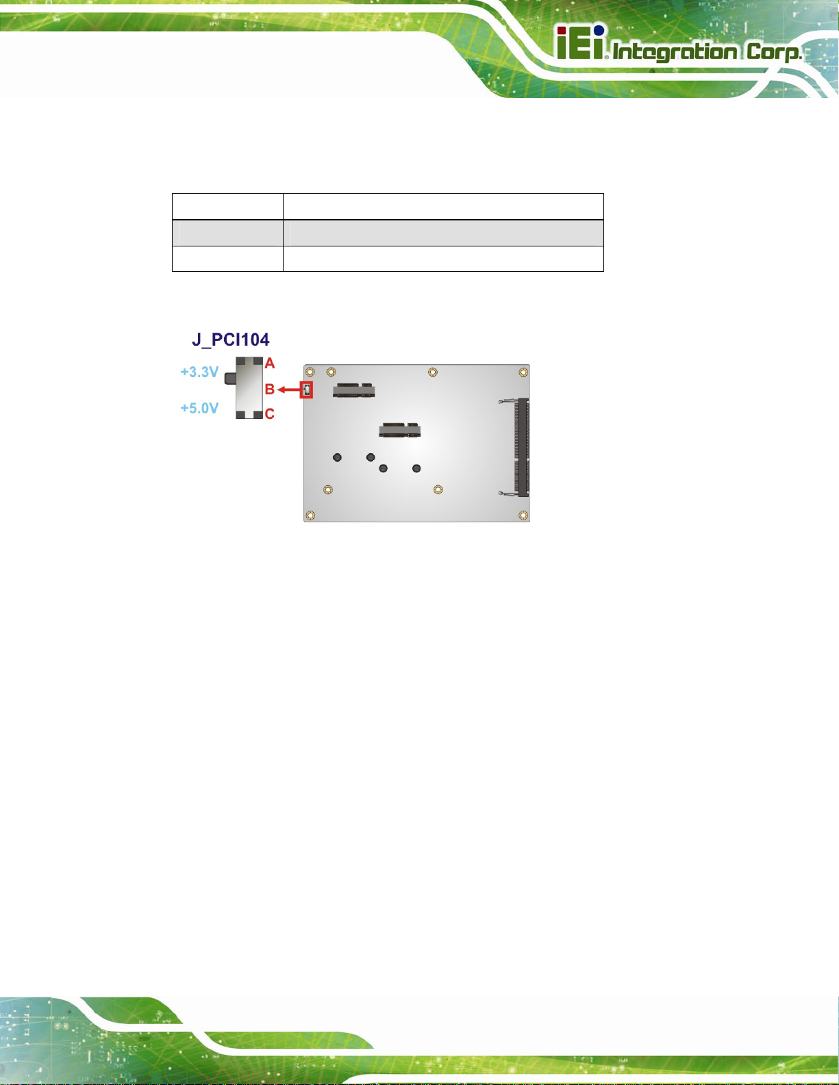
4.3.6 PCI-104 Voltage Selection
Use the J_PCI104 switch to select the voltage supplied to the PCI-104 expansion module.
Setting Description
A-B +3.3 V (Default)
B-C +5.0 V
Table 4-4: PCI-104 Voltage Switch Settings
Figure 4-9: PCI-104 Voltage Switch Location
4.3.7 USB Power Select
The USB power selection is made through the BIOS option in “Chipset South Bridge”
BIOS menu. Use the USB Power SW1 BIOS option to configure the power source to the
following USB ports:
CN7 (external USB 3.0 port)
CN6 (external USB 2.0 port)
Please refer to Section 5.4.2 for detailed information.
USB1 (internal USB 2.0 port)
Page 67
Page 82

4.4 Internal Peripheral Device Connections
This section outlines the installation of peripheral devices to the on-board connectors.
4.4.1 AT Power Connection
Follow the instructions below to connect the NANO-BT to an AT power supply.
WARNING:
Disconnect the power supply power cord from its AC power source to
prevent a sudden power surge to the NANO-BT.
Step 1: Locate the power cable. The power cable is shown in the packing list in
Chapter 2.
NANO-BT EPIC SBC
Step 2: Connect the Power Cable to the Motherboard. Connect the 4-pin (2x2) Molex
type power cable connector to the +12V power connector on the motherboard.
See Figure 4-10.
Page 68
Figure 4-10: Power Cable to Motherboard Connection
Page 83

NANO-BT EPIC SBC
Step 3: Connect Power Cable to Power Supply. Connect one of the 4-pin (1x4) Molex
type power cable connectors to an AT power supply. See Figure 4-11.
Figure 4-11: Connect Power Cable to Power Supply
4.4.2 SATA Drive Connection
The NANO-BT is shipped with two SATA drive cables. To connect the SATA drive to the
connector, please follow the steps below.
Step 1: Locate the SATA connector and the SATA power connector. The locations of
the connectors are shown in Chapter 3.
Step 2: Insert the cable connector. Insert the cable connector into the on-board SATA
drive connector and the SATA power connector. See Figure 4-12.
Page 69
Page 84

NANO-BT EPIC SBC
Figure 4-12: SATA Drive Cable Connection
Step 3: Connect the cable to the SATA disk. Connect the connector on the other end
of the cable to the connector at the back of the SATA drive. See Figure 4-12.
Step 4: T
o remove the SATA cable from the SATA connector, press the clip on the
connector at the end of the cable. Step 0:
4.4.3 Single RS-232 Cable Connection
The single RS-232 cable consists of one serial port connector attached to a serial
communications cable that is then attached to a D-sub 9 male connector that is mounted
onto a bracket. To install the single RS-232 cable, please follow the steps below.
Step 1: Locate the RS-232 connector. The location of the RS-232 connector is shown
in Chapter 3.
Step 2: Insert the cable connector. Align pin 1 on the on-board serial port pin header
Page 70
with pin 1 on the serial port connector. Pin 1 on the serial port connector is
indicated with a white dot. Insert the connector into the serial port pin header.
See Figure 4-13.
Page 85

NANO-BT EPIC SBC
Figure 4-13: Single RS-232 Cable Installation
Step 3: Secure the bracket. The single RS-232 connector has one D-sub 9 male
connector secured to a bracket. To secure the bracket to the chassis please
refer to the reference material that came with the chassis. Step 0:
4.5 IPMI Setup Procedure (for NANO-BT-i1 Models Only)
The NANO-BT-i1 features Intelligent Platform Management Interface (IPMI) that helps
lower the overall costs of server management by enabling users to maximize IT resources,
save time and manage multiple systems. The NANO-BT-i1 supports IPMI 2.0 through the
optional iRIS-1010 module. Follow the steps below to setup IPMI.
4.5.1 Managed System Hardware Setup
The hardware configuration of the managed system (NANO-BT) is described bel ow.
Step 1: Install an iRIS-1010 module to the IPMI module socket (refer to Section 4.2.2).
Step 2: Make
sure a DDR3L SO-DIMM is installed in the SO-DIMM socket.
Step 3: Connect an Ethernet cable to the RJ-45 connector labeled LAN1 (Figure 3-32).
Page 71
Page 86

NANO-BT EPIC SBC
Chapter
5
5 BIOS
Page 72
Page 87

NANO-BT EPIC SBC
5.1 Introduction
The BIOS is programmed onto the BIOS chip. The BIOS setup program allows changes t o
certain system settings. This chapter outlines the options that can be changed.
NOTE:
Some of the BIOS options may vary throughout the life cycle of the
product and are subject to change without prior notice.
5.1.1 Starting Setup
The UEFI BIOS is activated when the computer is turned on. The setup program can be
activated in one of two ways.
1. Press the DEL or F2 key as soon as the system is turned on or
2. Press the DEL or F2 key when the “Press DEL or F2 to enter SETUP”
message appears on the screen.
If the message disappears before the DEL or F2 key is pressed, restart the computer and
try again.
5.1.2 Using Setup
Use the arrow keys to highlight items, press ENTER to select, use the PageUp and
PageDown keys to change entries, press F1 for help and press E
keys are shown in Table 5-1.
Key Function
Up arrow Move to previous item
Down arrow Move to next item
Left arrow Move to the item on the left hand side
SC to quit. Navigation
Right arrow Move to the item on the right hand side
Page 73
Page 88

Key Function
+ Increase the numeric value or make changes
- Decrease the numeric value or make changes
Esc key Main Menu – Quit and not save changes into CMOS
Status Page Setup Menu and Option Page Setup Menu -Exit current page and return to Main Menu
F1 key General help, only for Status Page Setup Menu and Option
Page Setup Menu
F2 key Load previous values
F3 key Load optimized default s
NANO-BT EPIC SBC
F4 key Save changes and Exit BIOS
Table 5-1: BIOS Navigation Keys
5.1.3 Getting Help
When F1 is pressed a small help window describing the appropriate keys to use and the
possible selections for the highlighted item appears. To exit the Help Window press E
or the F1 key again.
5.1.4 Unable to Reboot after Configuration Changes
If the computer cannot boot after changes to the system configuration is made, CMOS
defaults. Use the clear CMOS button described in Chapter 4.
5.1.5 BIOS Menu Bar
The menu bar on top of the BIOS screen has the following main items:
SC
Page 74
Main – Changes the basic system configuration.
Advanced – Changes the advanced system settings.
Chipset – Changes the chipset settings.
Boot – Changes the system boot configuration.
Page 89
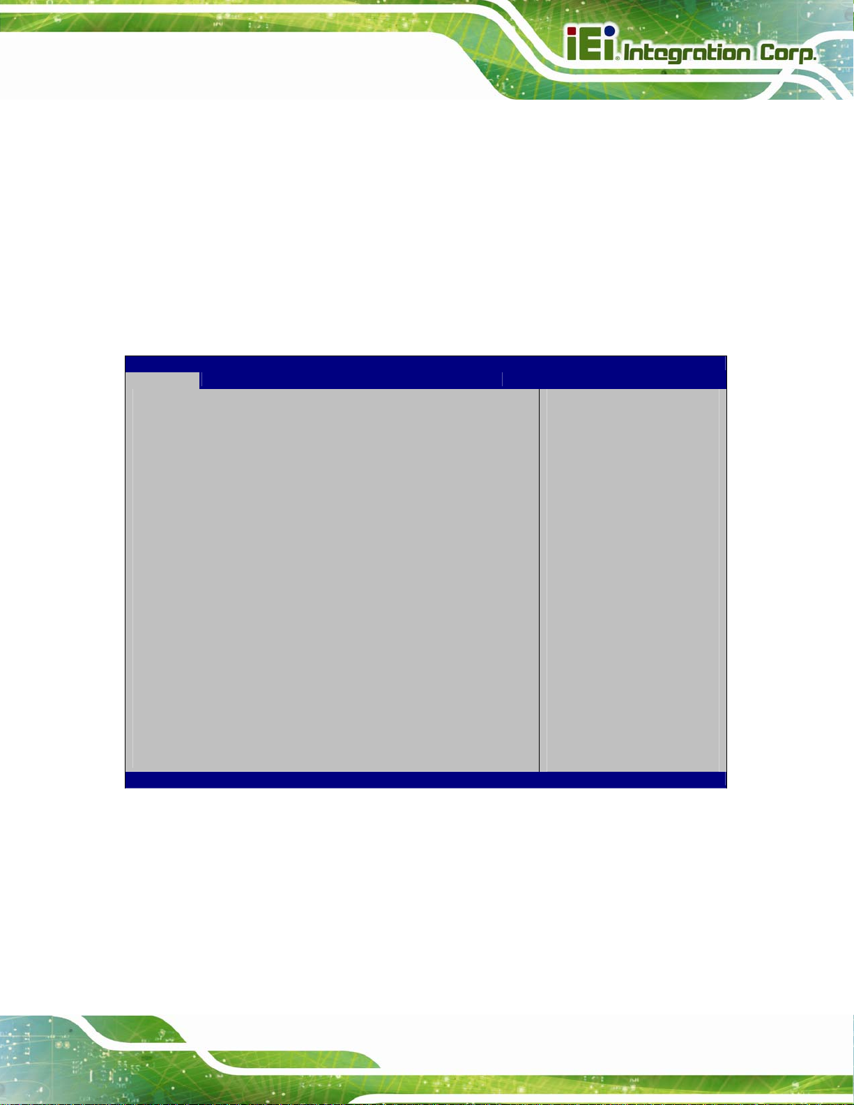
NANO-BT EPIC SBC
Security – Sets User and Supervisor Passwords.
Save & Exit – Selects exit options and loads default settings
The following sections completely describe the configuration options found in the menu
items at the top of the BIOS screen and listed above.
5.2 Main
The Main BIOS menu (BIOS Menu 1) appears when the BIOS Setup program is entered.
The Main menu gives an overview of the basic system information.
Aptio Setup Utility – Copyright (C) 2013 American Megatrends, Inc.
Main Advanced Chipset Security Boot Save & Exit
BIOS Information
BIOS Vendor American Megatrends
Core Version 5.009
Compliency UEFI 2.3;PI1.2
Project Version B348AI12.ROM
Build Date 04/20/2015 18:18:06
iWDD Vendor iEi
iWDD Version B348ER12.bin
CPU Configuration
Microcode Patch 901
BayTrail SoC D0 Stepping
Memory Information
Total Memory 2048 MB (LPDDR3)
TXE Information
Sec RC Version 00.05.00.00
TXE FW Version 01.00.02.1060
System Date [Wed 05/27/2015]
System Time [15:10:27]
Version 2.16.1242. Copyright (C) 2013 American Megatrends, Inc.
Set the Date. Use Tab to
switch between Data
elements.
----------------------
: Select Item
Enter Select
+ -: Change Opt.
F1: General Help
F2: Previous Values
F3: Optimized Defaults
F4: Save & Exit
ESC: Exit
: Select Screen
BIOS Menu 1: Main
The System Overview field has two user configurable fields:
System Date [xx/xx/xx]
Use the System Date option to set the system date. Manually enter the day, month and
year.
Page 75
Page 90

System Time [xx:xx:xx]
Use the System Time option to set the system time. Manually enter the hours, minutes
and seconds.
5.3 Advanced
Use the Advanced menu (BIOS Menu 2) to configure the CPU and peripheral devices
through the following sub-menus:
NANO-BT EPIC SBC
WARNING!
Setting the wrong values in the sections below may cause the system
to malfunction. Make sure that the settings made are compatible with
the hardware.
Aptio Setup Utility – Copyright (C) 2013 American Megatrends, Inc.
Main Advanced Chipset Security Boot Save & Exit
> ACPI Settings
> F81866 Super IO Configuration
> iWDD H/W Monitor
> RTC Wake Settings
> Serial Port Console Redirection
> iEi Feature
> CPU Configuration
> IDE Configuration
> USB Configuration
Version 2.16.1242. Copyright (C) 2013 American Megatrends, Inc.
BIOS Menu 2: Advanced
System ACPI Parameters
----------------------
: Select Item
Enter Select
+ - Change Opt.
F1 General Help
F2 Previous Values
F3 Optimized Defaults
F4 Save & Exit
ESC Exit
: Select Screen
Page 76
Page 91
S
NANO-BT EPIC SBC
5.3.1 ACPI Settings
The ACPI Settings menu (BIOS Menu 3) configures the Advanced Configuration and
Power Interface (ACPI) options.
Aptio Setup Utility – Copyright (C) 2013 American Megatrends, Inc.
Advanced
ACPI Settings
ACPI Sleep State [S3 (Suspend to RAM)]
Version 2.16.1242. Copyright (C) 2013 American Megatrends, Inc.
elect the highest ACPI
sleep state the system
will enter when the
SUSPEND button is
pressed.
----------------------
: Select Screen
: Select Item
Enter Select
+ - Change Opt.
F1 General Help
F2 Previous Values
F3 Optimized Defaults
F4 Save & Exit
ESC Exit
BIOS Menu 3: ACPI Configuration
ACPI Sleep State [S3 (Suspend to RAM)]
Use the ACPI Sleep State option to specify the sleep state the system enters when it is
not being used.
S3 (Suspend to
RAM)
DEFAULT
The caches are flushed and the CPU is powered
off. Power to the RAM is maintained. The
computer returns slower to a working state, but
more power is saved.
Page 77
Page 92

S
E
NANO-BT EPIC SBC
5.3.2 F81866 Super IO Configuration
Use the F81866 Super IO Configuration menu (BIOS Menu 4) to set or change the
configurations for the serial ports.
Aptio Setup Utility – Copyright (C) 2013 American Megatrends, Inc.
Advanced
F81866 Super IO Configuration
F81866 Super IO Chip F81866
> Serial Port 1 Configuration
> Serial Port 2 Configuration
> Serial Port 3 Configuration
> Serial Port 4 Configuration
Version 2.16.1242. Copyright (C) 2013 American Megatrends, Inc.
et Parameters of Serial
Port 1 (COMA)
---------------------
: Select Screen
: Select Item
Enter Select
+ - Change Opt.
F1 General Help
F2 Previous Values
F3 Optimized Defaults
F4 Save & Exit
ESC Exit
BIOS Menu 4: F81866 Super IO Configuration
5.3.2.1 Serial Port n Configuration
Use the Serial Port n Configuration menu (BIOS Menu 5) to configure the serial port n.
Aptio Setup Utility – Copyright (C) 2013 American Megatrends, Inc.
Advanced
Serial Port n Configuration
Serial Port [Enabled]
Device Settings IO=3F8h;IRQ=4
Change Settings [Auto]
Version 2.16.1242. Copyright (C) 2013 American Megatrends, Inc.
nable or Disable Serial
Port (COM)
---------------------
: Select Screen
: Select Item
Enter Select
= - Change Opt.
F1 General Help
F2 Previous Values
F3 Optimized Defaults
F4 Save & Exit
ESC Exit
BIOS Menu 5: Serial Port n Configuration Menu
Page 78
Page 93

NANO-BT EPIC SBC
5.3.2.1.1 Serial Port 1 Configuration
Serial Port [Enabled]
Use the Serial Port option to enable or disable the serial port.
Disabled
Enabled DEFAULT
Change Settings [Auto]
Use the Change Settings option to change the serial port IO port address and interrupt
address.
Auto DEFAULT
IO=3F8h;
IRQ=4
IO=3F8h;
IRQ=3, 4
IO=2F8h;
IRQ=3, 4
Disable the serial port
Enable the serial port
The serial port IO port address and interrupt address
are automatically detected.
Serial Port I/O port address is 3F8h and the interrupt
address is IRQ4
Serial Port I/O port address is 3F8h and the interrupt
address is IRQ3, 4
Serial Port I/O port address is 2F8h and the interrupt
address is IRQ3, 4
IO=3E8h;
IRQ=3, 4
IO=2E8h;
IRQ=3, 4
Serial Port I/O port address is 3E8h and the interrupt
address is IRQ3, 4
Serial Port I/O port address is 2E8h and the interrupt
address is IRQ3, 4
Page 79
Page 94

5.3.2.1.2 Serial Port 2 Configuration
Serial Port [Enabled]
Use the Serial Port option to enable or disable the serial port.
NANO-BT EPIC SBC
Disabled
Enabled DEFAULT
Change Settings [Auto]
Use the Change Settings option to change the serial port IO port address and interrupt
address.
Auto DEFAULT
IO=2F8h;
IRQ=3
IO=3F8h;
IRQ=3, 4
IO=2F8h;
IRQ=3, 4
Disable the serial port
Enable the serial port
The serial port IO port address and interrupt address
are automatically detected.
Serial Port I/O port address is 2F8h and the interrupt
address is IRQ3
Serial Port I/O port address is 3F8h and the interrupt
address is IRQ3, 4
Serial Port I/O port address is 2F8h and the interrupt
address is IRQ3, 4
Page 80
IO=3E8h;
IRQ=3, 4
IO=2E8h;
IRQ=3, 4
Serial Port I/O port address is 3E8h and the interrupt
address is IRQ3, 4
Serial Port I/O port address is 2E8h and the interrupt
address is IRQ3, 4
Page 95

NANO-BT EPIC SBC
5.3.2.1.3 Serial Port 3 Configuration
Serial Port [Enabled]
Use the Serial Port option to enable or disable the serial port.
Disabled
Enabled DEFAULT
Change Settings [Auto]
Use the Change Settings option to change the serial port IO port address and interrupt
address.
Auto DEFAULT
IO=3E8h;
IRQ=10
IO=3F8h;
IRQ=10, 11
IO=2F8h;
IRQ=10, 11
Disable the serial port
Enable the serial port
The serial port IO port address and interrupt address
are automatically detected.
Serial Port I/O port address is 3E8h and the interrupt
address is IRQ10
Serial Port I/O port address is 3F8h and the interrupt
address is IRQ10, 11
Serial Port I/O port address is 2F8h and the interrupt
address is IRQ10, 11
IO=3E8h;
IRQ=10, 11
IO=2E8h;
IRQ=10, 11
IO=2E0h;
IRQ=10, 11
Serial Port I/O port address is 3E8h and the interrupt
address is IRQ10, 11
Serial Port I/O port address is 2E8h and the interrupt
address is IRQ10, 11
Serial Port I/O port address is 2E0h and the interrupt
address is IRQ10, 11
Page 81
Page 96

5.3.2.1.4 Serial Port 4 Configuration
Serial Port [Enabled]
Use the Serial Port option to enable or disable the serial port.
NANO-BT EPIC SBC
Disabled
Enabled DEFAULT
Change Settings [Auto]
Use the Change Settings option to change the serial port IO port address and interrupt
address.
Auto DEFAULT
IO=2E8h;
IRQ=10
IO=3F8h;
IRQ=10, 11
IO=2F8h;
IRQ=10, 11
Disable the serial port
Enable the serial port
The serial port IO port address and interrupt address
are automatically detected.
Serial Port I/O port address is 2E8h and the interrupt
address is IRQ10
Serial Port I/O port address is 3F8h and the interrupt
address is IRQ10, 11
Serial Port I/O port address is 2F8h and the interrupt
address is IRQ10, 11
Page 82
IO=3E8h;
IRQ=10, 11
IO=2E8h;
IRQ=10, 11
IO=2E0h;
IRQ=10, 11
Serial Port I/O port address is 3E8h and the interrupt
address is IRQ10, 11
Serial Port I/O port address is 2E8h and the interrupt
address is IRQ10, 11
Serial Port I/O port address is 2E0h and the interrupt
address is IRQ10, 11
Page 97

NANO-BT EPIC SBC
5.3.3 iWDD H/W Monitor
The iWDD H/W Monitor menu (BIOS Menu 6) contains the fan configuration submenus
and displays operating temperature, fan speeds and system voltages.
Aptio Setup Utility – Copyright (C) 2013 American Megatrends, Inc.
Advanced
PC Health Status
CPU temperature :+47 °C
System temperature :+42 °C
CPU_FAN1 Speed :N/A
SYS_FAN1 Speed :N/A
CPU_CORE :+0.904 V
+5V :+5.128 V
+12V :+12.232 V
+DDR :+1.348 V
+5VSB :+5.064 V
+3.3V :+3.312 V
+3.3VSB :+3.312 V
> Smart Fan Mode Configuration
Version 2.16.1242. Copyright (C) 2013 American Megatrends, Inc.
Smart Fan Mode Select
---------------------
: Select Screen
: Select Item
Enter Select
+ - Change Opt.
F1 General Help
F2 Previous Values
F3 Optimized Defaults
F4 Save & Exit
ESC Exit
BIOS Menu 6: iWDD H/W Monitor
PC Health Status
The following system parameters and values are shown. The system parameters that are
monitored are:
System Temperatures:
o CPU Temperature
o System Temperature
Fan Speeds:
o CPU Fan Speed
o System Fan Speed
Voltages:
o CPU_CORE
o +5V
o +12V
Page 83
Page 98

NANO-BT EPIC SBC
o +DDR
o +5VSB
o +3.3V
o +3.3VSB
5.3.3.1 Smart Fan Mode Configuration
Use the Smart Fan Mode Configuration submenu (BIOS Menu 7) to configure smart fan
temperature and speed settings.
Aptio Setup Utility – Copyright (C) 2013 American Megatrends, Inc.
Advanced
Smart Fan Mode Configuration
CPU_FAN1 Smart Fan Control [Manual Mode]
Manual Mode 70
SYS_FAN1 Smart Fan Control [Auto Mode]
Auto mode fan start temperature 50
Auto mode fan off temperature 40
Auto mode fan start PWM 30
Auto mode fan slope PWM 1
Version 2.16.1242. Copyright (C) 2013 American Megatrends, Inc.
Smart Fan Mode Select
---------------------
: Select Screen
: Select Item
Enter Select
+ - Change Opt.
F1 General Help
F2 Previous Values
F3 Optimized Defaults
F4 Save & Exit
ESC Exit
BIOS Menu 7: Smart Fan Mode Configuration
CPU_FAN1 Smart Fan Control [Manual Mode]
Use the CPU_FAN1 Smart Fan Control option to configure the CPU Smart Fan.
Manual Mode
Use the + or – key to change the Manual Mode value. Enter a decimal number between 1
and 100.
Page 84
Manual Mode DEFAULT
The fan spins at the speed set in Manual Mode
settings.
Page 99

NANO-BT EPIC SBC
SYS_FAN1 Smart Fan Control [Auto Mode]
Use the SYS_FAN1 Smart Fan Control option to configure the System Smart Fan.
Manual Mode
Auto Mode DEFAULT
Auto mode fan start/off temperature
Use the + or – key to change the Auto mode fan start/off temperature value. Enter a
decimal number between 1 and 100.
Auto mode fan start PWM
Use the + or – key to change the Auto mode fan start PWM value. Enter a decimal
number between 1 and 100.
Auto mode fan slope PWM
Use the + or – key to change the Auto mode fan slope PWM value. Enter a decimal
The fan spins at the speed set in Manual Mode
settings.
The fan adjusts its speed using Auto Mode
settings.
number between 1 and 64.
Page 85
Page 100

s
NANO-BT EPIC SBC
5.3.4 RTC Wake Settings
The RTC Wake Settings menu (BIOS Menu 8) configures RTC wake event. The RTC
wake function is supported in ACPI (S3/S4/S5) and APM soft off modes.
Aptio Setup Utility – Copyright (C) 2013 American Megatrends, Inc.
Advanced
Wake System with Fixed Time [Disabled]
Version 2.16.1242. Copyright (C) 2013 American Megatrends, Inc.
Enables or Disables
system wake on alarm
event. When enabled,
ystem will wake on the
date: hr: min: sec
specified.
----------------------
: Select Screen
: Select Item
Enter Select
+ - Change Opt.
F1 General Help
F2 Previous Values
F3 Optimized Defaults
F4 Save & Exit
ESC Exit
BIOS Menu 8: RTC Wake Settings
Wake System with Fixed Time [Disabled]
Use the Wake System with Fixed Time option to specify the time the system should be
roused from a suspended state.
Disabled DEFAULT
The real time clock (RTC) cannot generate a wake
event
Page 86
 Loading...