

Page 1

NANO-AL EPIC SBC
Page i
EPIC SBC with 14nm Intel® Pentium®/Celeron®/Atom® SoC,
MODEL:
NANO-AL
Rev. 1.03 – May 28, 2018
Dual HDMI, iDP, LVDS, Dual PCIe GbE, USB 3.0, PCIe Mini,
M.2, SATA 6Gb/s, COM and HD Audio, -40ºC ~ 85ºC
User Manual
Page 2

NANO-AL EPIC SBC
Page ii
Date Version Changes
Revision
May 28, 2018
May 3, 2018 1.02 Minor update
March 27, 2018 1.01 Changed the SIM card slot to optional item
December 11, 2017 1.00 Initial release
1.03 Modified “Table 1-1: Model Variations”
Page 3

NANO-AL EPIC SBC
Page iii
Copyright
COPYRIGHT NOTICE
The information in this document is subject to change without prior notice in order to
improve reliability, design and function and does not represent a commitment on the part
of the manufacturer.
In no event will the manufacturer be liable for direct, indirect, special, incidental, or
consequential damages arising out of the use or inability to use the product or
documentation, even if advised of the possibil ity of such damages.
This document contains proprietary information protected by copyright. All rights are
reserved. No part of this manual may be reproduced by any mechanical, electronic, or
other means in any form without prior written permission of the manufacturer.
TRADEMARKS
All registered trademarks and product names mentioned herein are used for identification
purposes only and may be trademarks and/or registered trademarks of their respective
owners.
Page 4
NANO-AL EPIC SBC
Page iv
Manual Conventions
WARNING
Warnings appear where overlooked details may cause damage to th e
equipment or result in personal injury. Warnings should be taken
seriously.
CAUTION
Cautionary messages should be heeded to help red uce the chance of
losing data or damaging the product.
NOTE
These messages inform the reader of essenti al but non-critical
information. These messages should be read carefully as any directions
or instructions contained therein can help avoid making mistakes.
HOT SURFACE
This symbol indicates a hot surface that shoul d not be touched without
taking care.
Page 5

NANO-AL EPIC SBC
Page v
Table of Contents
1 INTRODUCTION .......................................................................................................... 1
1.1 INTRODUCTION ........................................................................................................... 2
1.2 MODEL VARIATIONS ................................................................................................... 3
1.3 FEATURES ................................................................................................................... 3
1.4 CONNECTORS ............................................................................................................. 4
1.5 DIMENSIONS ............................................................................................................... 6
1.6 DATA FLOW ................................................................................................................ 7
1.7 TECHNICAL SPECIFICATIONS ...................................................................................... 8
2 PACKING LIST ............................................................................................................ 11
2.1 ANTI-STATIC PRECAUTIONS ...................................................................................... 12
2.2 UNPACKING PRECAUTIONS ....................................................................................... 12
2.3 PACKING LIST ........................................................................................................... 13
2.4 OPTIONAL ITEMS ...................................................................................................... 14
3 CONNECTORS ........................................................................................................... 15
3.1 PERIPHERAL INTERFACE CONNECTORS ..................................................................... 16
3.1.1 Layout .............................................................................................................. 16
3.1.2 Peripheral Interface Connectors ..................................................................... 17
3.1.3 External Interface Panel Connectors ............................................................... 18
3.2 INTERNAL PERIPHERAL CONNECTORS ...................................................................... 19
3.2.1 9 V ~ 30 V Power Connector ........................................................................... 19
3.2.2 Audio Connector .............................................................................................. 20
3.2.3 Backlight Inverter Connector .......................................................................... 20
3.2.4 Battery Connector ............................................................................................ 21
3.2.5 BIOS Debug Connector ................................................................................... 23
3.2.6 Buzzer Connector ............................................................................................. 24
3.2.7 Chassis Intrusion Connector ............................................................................ 25
3.2.8 CPU Fan Connector ........................................................................................ 26
3.2.9 Digital I/O Connector ...................................................................................... 27
3.2.10 EC Debug Connector ..................................................................................... 28
Page 6

NANO-AL EPIC SBC
Page vi
3.2.11 Front Panel Connector ................................................................................... 29
3.2.12 I2C Connector ................................................................................................ 30
3.2.13 Internal DisplayPort Connector .................................................................... 31
3.2.14 Keyboard and Mouse Connector ................................................................... 32
3.2.15 LAN LED Connectors .................................................................................... 33
3.2.16 LVDS Connector ............................................................................................ 34
3.2.17 microSD Card Slot (Optional) ....................................................................... 35
3.2.18 M.2 Slot .......................................................................................................... 36
3.2.19 PCIe Mini Card Slot ...................................................................................... 37
3.2.20 Power Button (On-board) .............................................................................. 38
3.2.21 Power Button Connector ................................................................................ 39
3.2.22 Reset Button Connector ................................................................................. 40
3.2.23 SATA 6Gb/s Drive Connectors ....................................................................... 40
3.2.24 SATA Power Connectors (5 V) ....................................................................... 41
3.2.25 Serial Port Connector, RS-232 ....................................................................... 42
3.2.26 Serial Port Connector, RS-232/422/485 ........................................................ 43
3.2.27 SIM Card Slot (Optional) ............................................................................... 45
3.2.28 SMBus Connector .......................................................................................... 45
3.2.29 SO-DIMM Connector ..................................................................................... 46
3.2.30 SPI Flash Connector ...................................................................................... 47
3.2.31 SPI Flash Connector (EC) ............................................................................. 48
3.2.32 USB 2.0 Connector ........................................................................................ 48
3.3 EXTERNAL INTERFACE CONNECTORS ....................................................................... 49
3.3.1 HDMI Connectors ............................................................................................ 50
3.3.2 LAN Connectors ............................................................................................... 51
3.3.3 USB 2.0 Connectors ......................................................................................... 52
3.3.4 USB 3.0 Connectors ......................................................................................... 52
4 INSTALLATION ......................................................................................................... 53
4.1 ANTI-STATIC PRECAUTIONS ...................................................................................... 54
4.2 INSTALLATION CONSIDERATIONS .............................................................................. 54
4.3 SO-DIMM INSTALLATION ....................................................................................... 56
4.4 FULL-SIZE PCIE MINI CARD INSTALLATION ............................................................. 56
4.5 HALF-SIZE PCIE MINI CARD INSTALLATION ............................................................. 58
4.6 M.2 MODULE INSTALLATION .................................................................................... 60
Page 7

NANO-AL EPIC SBC
Page vii
4.7 SIM CARD INSTALLATION ........................................................................................ 62
4.8 SYSTEM CONFIGURATION ......................................................................................... 64
4.8.1 AT/ATX Power Mode Selection ........................................................................ 64
4.8.2 Clear CMOS Button ......................................................................................... 65
4.8.3 HDMI/DP Selection Switch ............................................................................. 65
4.8.4 LVDS Panel Type Selection .............................................................................. 66
4.8.5 LVDS Voltage Selection ................................................................................... 68
4.8.6 M.2 and SATA2 Selection Switch ..................................................................... 69
4.8.7 Flash Descriptor Security Override Jumper .................................................... 70
4.9 CHASSIS INSTALLATION ............................................................................................ 71
4.9.1 Airflow .............................................................................................................. 71
4.9.2 Motherboard Installation ................................................................................. 71
4.10 INTERNAL PERIPHERAL DEVICE CONNECTIONS ...................................................... 72
4.10.1 RS-232 Cable Connection .............................................................................. 72
4.10.2 SATA Drive Connection ................................................................................. 73
4.11 SOFTWARE INSTALLATION ...................................................................................... 74
4.11.1 Driver Download ............................................................................................ 75
5 BIOS .............................................................................................................................. 77
5.1 INTRODUCTION ......................................................................................................... 78
5.1.1 Starting Setup ................................................................................................... 78
5.1.2 Using Setup ...................................................................................................... 78
5.1.3 Getting Help ..................................................................................................... 79
5.1.4 Unable to Reboot after Configuration Changes .............................................. 79
5.1.5 BIOS Menu Bar ................................................................................................ 79
5.2 MAIN ........................................................................................................................ 80
5.3 ADVANCED ............................................................................................................... 81
5.3.1 Trusted Computing ........................................................................................... 82
5.3.2 ACPI Settings ................................................................................................... 83
5.3.3 F81866 Super IO Configuration ...................................................................... 84
5.3.3.1 Serial Port n Configuration ....................................................................... 84
5.3.4 iWDD H/W Monitor ......................................................................................... 90
5.3.5 USB Configuration ........................................................................................... 92
5.3.6 CPU Configuration .......................................................................................... 93
5.3.4.1 Smart Fan Mode Configuration ................................................................ 91
Page 8

NANO-AL EPIC SBC
Page viii
5.3.7 RTC Wake Settings ........................................................................................... 95
5.3.8 Power Saving Configuration ............................................................................ 96
5.3.9 Serial Port Console Redirection ...................................................................... 97
5.3.9.1 Legacy Console Redirection Settings ..................................................... 100
5.3.10 IEI Feature ................................................................................................... 101
5.4 CHIPSET ................................................................................................................. 102
5.4.1 North Bridge .................................................................................................. 102
5.4.1.1 Intel IGD Configuration .......................................................................... 103
5.4.1.2 LCD Control ........................................................................................... 105
5.4.2 Southbridge Configuration ............................................................................ 106
5.4.2.1 HD Audio Configuration ......................................................................... 108
5.4.2.2 PCI Express Configuration ..................................................................... 109
5.4.2.3 SATA Configuration ................................................................................. 112
5.5 SECURITY ................................................................................................................ 113
5.6 BOOT ....................................................................................................................... 114
5.7 SAVE & EXIT ........................................................................................................... 116
A REGULATORY COMPLIANCE ............................................................................. 117
B PRODUCT DISPOSAL ............................................................................................. 119
C BIOS OPTIONS ........................................................................................................ 121
D TERMINOLOGY ..................................................................................................... 124
E DIGITAL I/O INTERFACE ..................................................................................... 128
E.1 INTRODUCTION ...................................................................................................... 129
E.2 ASSEMBLY LANGUAGE SAMPLE 1 .......................................................................... 130
E.3 ASSEMBLY LANGUAGE SAMPLE 2 .......................................................................... 130
F HAZARDOUS MATERIALS DISCLOS U RE ........................................................ 131
Page 9

NANO-AL EPIC SBC
Page ix
List of Figures
Figure 1-1: NANO-AL ...................................................................................................................... 2
Figure 1-2: Connectors (Front Side) ............................................................................................. 4
Figure 1-3: Connectors (Solder Side) ........................................................................................... 5
Figure 1-4: NANO-AL Dimensions (mm) ...................................................................................... 6
Figure 1-5: Data Flow Diagram ...................................................................................................... 7
Figure 3-1: Peripheral Interface Connector s ............................................................................. 16
Figure 3-2: 9 V ~ 30 V Power Connector Location .................................................................... 19
Figure 3-3: Audio Connector Location ....................................................................................... 20
Figure 3-4: Backlight Inverter Connector Location ................................................................... 21
Figure 3-5: Battery Connector Location ..................................................................................... 22
Figure 3-6: BIOS Debug Connector Location ............................................................................ 23
Figure 3-7: Buzzer Connector Location ..................................................................................... 24
Figure 3-8: Chassis Intrusion Connector Location ................................................................... 25
Figure 3-9: CPU Fan Connector Location .................................................................................. 26
Figure 3-10: Digital I/O Connector Location .............................................................................. 27
Figure 3-11: EC Debug Connector Location .............................................................................. 28
Figure 3-12: Front Panel Connector Location ........................................................................... 29
Figure 3-13: I2C Connector Location .......................................................................................... 30
Figure 3-14: Internal DisplayPort Connector Location ............................................................. 31
Figure 3-15: Keyboard and Mouse Connector Location ........................................................... 32
Figure 3-16: LAN LED Connector Locations ............................................................................. 33
Figure 3-17: LVDS Connector Location...................................................................................... 34
Figure 3-18: microSD Card Slot Location .................................................................................. 35
Figure 3-19: M.2 Slot Location .................................................................................................... 36
Figure 3-20: PCIe Mini Card Slot Location ................................................................................. 37
Figure 3-21: On-board Power Button Location ......................................................................... 39
Figure 3-22: Power Button Connector Location ........................................................................ 39
Figure 3-23: Reset Button Connector Location ......................................................................... 40
Figure 3-24: SATA 6Gb/s Drive Connector Locations .............................................................. 41
Figure 3-25: 5 V SATA Power Connector Locations ................................................................. 42
Page 10

NANO-AL EPIC SBC
Page x
Figure 3-26: RS-232 Serial Port Connector Locations .............................................................. 42
Figure 3-27: RS-232/422/485 Serial Port Connector Locations ................................................ 44
Figure 3-28: SIM Card Slot Location ........................................................................................... 45
Figure 3-29: SMBus Connector Location ................................................................................... 46
Figure 3-30: SO-DIMM Connector Location ............................................................................... 46
Figure 3-31: SPI Flash Connector Location ............................................................................... 47
Figure 3-32: EC SPI Flash Connector Location ......................................................................... 48
Figure 3-33: USB 2.0 Connector Location ................................................................................. 49
Figure 3-34: External Interface Connectors ............................................................................... 49
Figure 3-35: HDMI Connector Pinout Locations ........................................................................ 50
Figure 3-36: LAN Connector ........................................................................................................ 51
Figure 4-1: SO-DIMM Installation ................................................................................................ 56
Figure 4-2: Removing the Retention Screw ............................................................................... 57
Figure 4-3: Inserting the Full-size PCIe Mini Card into the Slot at an Angle .......................... 57
Figure 4-4: Securing the Full-size PCIe Mini Card .................................................................... 58
Figure 4-5: Installing the Standoff .............................................................................................. 59
Figure 4-6: Inserting the Half-size PCIe Mini Card into the Slot at an Angle .......................... 59
Figure 4-7: Securing the Half-size PCIe Mini Card .................................................................... 60
Figure 4-8: Removing the M.2 Module Retention Screw .......................................................... 61
Figure 4-9: Inserting the M.2 Module into the Slot at an Angle ............................................... 61
Figure 4-10: Securing the M.2 Module ........................................................................................ 62
Figure 4-11: Unlock SIM Card Slot Cover .................................................................................. 62
Figure 4-12: SIM Card Installation ............................................................................................... 63
Figure 4-13: Lock SIM Card Slot Cover ...................................................................................... 63
Figure 4-14: AT/ATX Power Mode Switch Location .................................................................. 64
Figure 4-15: Clear CMOS Button Location ................................................................................. 65
Figure 4-16: HDMI/DP Selection Switch Location ..................................................................... 66
Figure 4-17: LVDS Panel Type Selection Switch Lo cati o n ....................................................... 67
Figure 4-18: LVDS Voltage Selection Jumper Location ........................................................... 68
Figure 4-19: M.2 and SATA2 Selection Switch Location .......................................................... 69
Figure 4-20: Flash Descriptor Security Override Jumper Location ........................................ 70
Figure 4-21: Single RS-232 Cable Installation ........................................................................... 72
Figure 4-22: SATA Drive Cable Connection ............................................................................... 73
Figure 4-23: IEI Resource Download Center .............................................................................. 74
Page 11

NANO-AL EPIC SBC
Page xi
List of Tables
Table 1-1: Model Variations ........................................................................................................... 3
Table 1-2: Technical Specifications ............................................................................................ 10
Table 2-1: Packing List ................................................................................................................. 13
Table 2-2: Optional Items ............................................................................................................. 14
Table 3-1: Peripheral Interface Connectors ............................................................................... 18
Table 3-2: Rear Panel Connectors .............................................................................................. 18
Table 3-3: 9 V ~ 30 V Power Connector Pinouts ........................................................................ 19
Table 3-4: Audio Connector Pinouts .......................................................................................... 20
Table 3-5: Backlight Inverter Connector Pinouts ...................................................................... 21
Table 3-6: Battery Connector Pinouts ........................................................................................ 22
Table 3-7: BIOS Debug Connector Pinouts ............................................................................... 23
Table 3-8: Buzzer Connector Pinouts ......................................................................................... 24
Table 3-9: Chassis Intrusion Connector Pinouts ...................................................................... 25
Table 3-10: CPU Fan Connector Pinouts ................................................................................... 26
Table 3-11: Digital I/O Connector Pinouts .................................................................................. 27
Table 3-12: EC Debug Connector Pinouts ................................................................................. 28
Table 3-13: Front Panel Connector Pinouts ............................................................................... 29
Table 3-14: I2C Connector Pinouts .............................................................................................. 30
Table 3-15: Internal DisplayPort Connector Pinouts ................................................................ 32
Table 3-16: Keyboard and Mouse Connector Pinouts .............................................................. 33
Table 3-17: LAN LED Connector Pinouts ................................................................................... 33
Table 3-18: LVDS Connector Pinouts ......................................................................................... 35
Table 3-19: PCIe Mini Card Slot Pinouts .................................................................................... 38
Table 3-20: Power Button Connector Pinouts ........................................................................... 39
Table 3-21: Reset Button Connector Pinouts ............................................................................ 40
Table 3-22: SATA 6Gb/s Drive Connector Pinouts .................................................................... 41
Table 3-23: 5 V SATA Power Connector Pinouts ...................................................................... 42
Table 3-24: RS-232 Serial Port Connector Pinouts ................................................................... 43
Table 3-25: RS-232/422/485 Serial Port Connector Pinouts ..................................................... 44
Table 3-26: DB-9 RS-232/422/485 Pinouts .................................................................................. 44
Page 12

NANO-AL EPIC SBC
Page xii
Table 3-27: SMBus Connector Pinouts ...................................................................................... 46
Table 3-28: SPI Flash Connector Pinouts .................................................................................. 47
Table 3-29: EC SPI Flash Connector Pinouts ............................................................................ 48
Table 3-30: USB 2.0 Connector Pinouts ..................................................................................... 49
Table 3-31: HDMI Connector Pinouts ......................................................................................... 50
Table 3-32: LAN Pinouts .............................................................................................................. 51
Table 3-33: USB 2.0 Port Pinouts ................................................................................................ 52
Table 3-34: USB 3.0 Port Pinouts ................................................................................................ 52
Table 4-1: AT/ATX Power Mode Switch Settings ....................................................................... 64
Table 4-2: HDMI/DP Selection Switch Settings .......................................................................... 65
Table 4-3: LVDS Panel Type Selection ....................................................................................... 67
Table 4-4: LVDS Voltage Selection Jumper Settings ................................................................ 68
Table 4-5: M.2 and SATA2 Selection Switch Settings ............................................................... 69
Table 4-6: Flash Descriptor Security Override Jumper Settings ............................................. 70
Table 5-1: BIOS Navigation Keys ................................................................................................ 79
Table 5-2: BIOS Options and Configured USB Ports ..............................................................107
Page 13

NANO-AL EPIC SBC
Page xiii
BIOS Menus
BIOS Menu 1: Main ....................................................................................................................... 80
BIOS Menu 2: Advanced .............................................................................................................. 81
BIOS Menu 3: Trusted Computing .............................................................................................. 82
BIOS Menu 4: ACPI Settings ....................................................................................................... 83
BIOS Menu 5: F81866 Super IO Configuration .......................................................................... 84
BIOS Menu 6: Serial Port n Configuration Menu ....................................................................... 84
BIOS Menu 7: iWDD H/W Monitor ............................................................................................... 90
BIOS Menu 8: Smart Fan Mode Configuration .......................................................................... 91
BIOS Menu 9: USB Configuration ............................................................................................... 92
BIOS Menu 10: CPU Configuration ............................................................................................. 93
BIOS Menu 11: RTC Wake Settings ............................................................................................ 95
BIOS Menu 12: Power Saving Configuration ............................................................................. 96
BIOS Menu 13: Serial Port Console Redirection ....................................................................... 97
BIOS Menu 14: Legacy Console Redirection Settings ...........................................................100
BIOS Menu 15: IEI Feature .........................................................................................................101
BIOS Menu 16: Chipset ..............................................................................................................102
BIOS Menu 17: North Bridge .....................................................................................................102
BIOS Menu 18: Intel IGD Configuration ....................................................................................103
BIOS Menu 19: LCD Control ......................................................................................................105
BIOS Menu 20: Southbridge Configuration .............................................................................106
BIOS Menu 21: HD-Audio Configuration ..................................................................................108
BIOS Menu 22: PCI Express Configuration .............................................................................109
BIOS Menu 23: Onboard LAN1/Onboard LAN2 Configuration ..............................................110
BIOS Menu 24: MPCIE1 Configuration .....................................................................................111
BIOS Menu 25: SATA Configuration .........................................................................................112
BIOS Menu 26: Security .............................................................................................................113
BIOS Menu 27: Boot ...................................................................................................................114
BIOS Menu 28: Save & Exit ........................................................................................................116
NANO-AL
Page 14

Page 15

NANO-AL EPIC SBC
Page 1
Chapter
1
1 Introduction
Page 16

NANO-AL EPIC SBC
Page 2
1.1 Introduction
Figure 1-1: NANO-AL
The NANO-AL is an EPIC form factor single bard computer. It has an on-board 14nm
®
Intel
Pentium®/Celeron®/Atom® SoC, and supports one 204-pin 1866/1600 MHz DDR3L
SDRAM SO-DIMM with up to 8 GB of memory.
The NANO-AL provides two GbE interfaces through the Intel
controllers. In addition, the NANO-AL comes with two HDMI, one internal DisplayPort and
one 18-bit/24-bit dual-channel LVDS connector for triple independent display.
Expansion and I/O include two USB 3.0 and two USB 2.0 on the rear panel, two USB 2.0
by pin header, two SATA 6Gb/s, four RS-232, two RS-232/422/485, one microSD card
slot (optional), one SI M card slot (optional), one PCIe Mini card slot and one M.2 slot. High
Definition Audio (HDA) support ensures HDA devices can be easily implemented on the
NANO-AL.
®
I211-AT PCIe GbE
Page 17

NANO-AL EPIC SBC
Page 3
1.2 Model Variations
The model variations for the NANO-AL series are listed in Table 1-1.
Model On-board SoC Operating Temp.
NANO-AL-N2
NANO-AL-N1
NANO-AL-E1W2*
NANO-AL-E2W2*
NANO-AL-E3W2*
*Production by order, MOQ 100 pcs/lot
Table 1-1: Model Variations
1.3 Features
Some of the NANO-AL motherboard features are listed below:
EPIC form factor
On-board 14nm Intel
Intel® Pentium® N4200 on-board SoC (up to
2.5 GHz, quad-core, 2 MB cache, TDP=6 W)
Intel® Celeron® N3350 on-board SoC (up to 2.4
GHz, dual-core, 2 MB cache, TDP=6 W)
Intel® Atom® x5-E3930 on-board SoC (up to
1.8 GHz, dual-core, 2 MB cache, TDP=6 W)
Intel® Atom® x5-E3940 on-board SoC (up to
1.8 GHz, quad-core, 2 MB cache, TDP=9 W)
Intel® Atom® x7-E3950 on-board SoC (up to
2.0 GHz, quad-core, 2 MB cache, TDP=12 W)
®
Pentium®/Celeron®/Atom® SoC
-20ºC ~ 70ºC
-20ºC ~ 70ºC
-40ºC ~ 85ºC
-40ºC ~ 85ºC
-40ºC ~ 85ºC
One 204-pin 1866/1600 MHz DDR3L SDRAM SO-DIMM slot supports up to 8 GB
Wide-range 9 V ~ 30 V power input design
Supports triple independent display
Complete I/O interfaces, including two USB 3.0, four USB 2.0, four RS-232,
two RS-232/422/485 and two SATA 6Gb/s
Flexible expansion options, including one P CIe Mini card slot, one SIM card
slot (optional), one microSD card slot (optional) and one M.2 slot
Supports wide-range operating temperature: -40ºC ~ 85ºC
RoHS compliant
Page 18

NANO-AL EPIC SBC
Page 4
1.4 Connectors
The connectors on the NANO-AL are shown in the following figures.
Figure 1-2: Connectors (Front Side)
Page 19

NANO-AL EPIC SBC
Page 5
Figure 1-3: Connectors (Solder Side)
Page 20

NANO-AL EPIC SBC
Page 6
Figure 1-4: NANO-AL Dimensions (mm)
1.5 Dimensions
The main dimensions of the NANO-AL are shown in the diagram below.
Page 21

NANO-AL EPIC SBC
Page 7
1.6 Data Flow
Figure 1-5 shows the data flow between the system chipset, the SoC and other
components installed on the motherboard.
Figure 1-5: Data Flow Diagram
Page 22

NANO-AL EPIC SBC
Page 8
1.7 Technical Specifications
The NANO-AL technical specifications are li st ed i n Table 1-2.
Form Factor
Onboard SoC
Memory
EPIC
Standard:
®
Pentium® N4200 on-board SoC (up to 2.5 GHz,
Intel
quad-core, 2 MB cache, TDP=6 W)
®
Intel
Celeron® N3350 on-board SoC (up to 2.4 GHz,
dual-core, 2 MB cache, TDP=6 W)
Production by order (MOQ 100):
®
Intel
Atom® x5-E3930 on-board SoC (up to 1.8 GHz,
dual-core, 2 MB cache, TDP=6 W)
®
Intel
Atom® x5-E3940 on-board SoC (up to 1.8 GHz,
quad-core, 2 MB cache, TDP=9 W)
®
Intel
Atom® x7-E3950 on-board SoC (up to 2.0 GHz,
quad-core, 2 MB cache, TDP=12 W)
One 204-pin 1866/1600 MHz DDR3L SDRAM SO-DIMM slot
supports up to 8 GB
Intel® HD Graphics Gen 9 with 18 execution units
Graphics Engine
4K codec decode & encode for HEVC 4, H.264, VP8, SVC
and MVC
Supports triple independent display
Two HDMI (up to 3840x2160@30 Hz)
Display Output
One 18/24-bit dual-channel LVDS (up to 1920x1200@60 Hz)
One iDP interface for HDMI, VGA, DVI and DisplayPort (up
to 1920x1200@60 Hz, co-lay with HDMI1)
BIOS
Ethernet
Audio
Super I/O Controller
Watchdog Timer
AMI UEFI BIOS
Dual Intel® I211-AT PCIe GbE controller
Realtek ALC662 HD codec
Fintek F81866
Software programmable, supports 1~255 sec. sy st em reset
Page 23

NANO-AL EPIC SBC
Page 9
One full-size/half-size PCIe Mini card slot (with optional SIM
card holder)
Expansions
I/O Interfaces
Audio Connector
Chassis Intrusion
Digital I/O
Ethernet
Fan Connector
Front Panel
I2C
Keyboard and Mouse
1 x M.2 2242 slot (B key , SATA, USB 2,0, USB 3.0 signal
only)
One microSD card slot (optional)
One front panel audio connector (10-pin header)
One 2-pin header
One 8-bit digital I/O
Two RJ-45 GbE ports
One smart fan connector by 4-pin wafer
One 6-pin wafer connector for power LED and HD D LED
One 2-pin wafer connector for power button
One 2-pin wafer connector for reset button
One 4-pin wafer connector
One 6-pin wafer connector for PS/2 keyboard and mouse
LAN LEDs
Serial ATA
Serial Ports
SMBus
USB Ports
Environmental and Power Specifications
Power Supply
Two 2-pin headers for LAN1 LED and LAN2 LED (link signal)
Two SATA 6Gb/s connectors (no RAID)
Two 5 V SATA power connectors
Four RS-232 by internal 10-pin headers
Two RS-232/422/485 by internal 10-pin headers
One 4-pin wafer connector
Two USB 3.0 ports on rear panel
Four USB 2.0 ports (two on rear panel, two by pin headers)
9 V ~ 30 V DC input
One internal 4-pin (2x2) power connector
Supports A T/A TX mode
Page 24

NANO-AL EPIC SBC
Page 10
12V@2.13A (Intel® Pentium® N4200 SoC with one 8 GB
1600 MHz DDR3L memory)
Power Consumption
12V@2.81A (Intel
1600 MHz DDR3L memory)
-20ºC ~ 70ºC (NANO-AL-Nx)
Operating Temperature
-40ºC ~ 85ºC (NANO-AL-ExW2)
®
Atom® x7-E3950 SoC with one 8 GB
Storage Temperature
Operating Humidity
Physical Specifications
Dimensions
Weight (GW/NW)
Table 1-2: Technical Specifications
-40ºC ~ 85ºC
5% ~ 95% (non-condensing)
115 mm x 165 mm
850 g/350 g
Page 25

NANO-AL EPIC SBC
Page 11
Chapter
2
2 Packing List
Page 26

NANO-AL EPIC SBC
Page 12
2.1 Anti-static Precautions
WARNING!
Static electricity can destroy certain el ectronics. Ma ke sure to follow the
ESD precautions to prevent damage to the product, and injury to the
user.
Make sure to adhere to the following guidelines:
Wear an anti-static wristband: Wearing an anti-static wristband can prevent
electrostatic discharge.
Self-grounding: Touch a grounded conductor every few minutes to dis charge
any excess static buildup.
Use an anti-static pad: When configuring any circuit board, place it on an
anti-static mat.
Only handle the edges of the PCB: Don't touch the surface of the
motherboard. Hold the motherboard by the edges when handling.
2.2 Unpacking Precautions
When the NANO-AL is unpacked, please do the f ol lowing:
Follow the anti-static guidelines above.
Make sure the packing box is facing upwards when opening.
Make sure all the packing list items are present .
Page 27

NANO-AL EPIC SBC
Page 13
2.3 Packing List
NOTE:
If any of the components listed in the checklist below are missing, do
not proceed with the installation. Contact the IEI reseller or vendor the
NANO-AL was purchased from or contact an IEI sales representative
directly by sending an email to sales@ieiworld.com
The NANO-AL is shipped with the following component s:
Quantity Item and Part Number Image
1 NANO-AL SBC
1 SATA signal and power cable
1 RS-232 cable
.
1 Power cable
1 Standoff and screw (for half-size PCIe Mini
card)
1 Quick installation guide
Table 2-1: Packing List
Page 28
NANO-AL EPIC SBC
Page 14
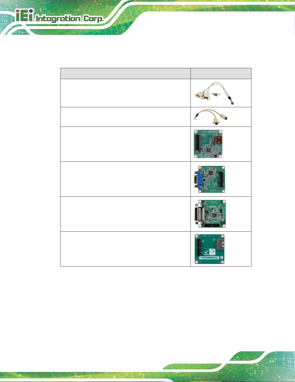
2.4 Optional Items
The following are optional components which may be separately purchased:
Item and Part Number Image
Dual-port USB cable, 210 mm, P=2.0
(P/N: 32000-070301-RS)
PS/2 keyboard and mouse Y cable, 135 mm, P=2.0
(P/N: 32000-023800-RS)
DisplayPort to HDMI converter board (for IEI iDP
connector)
(P/N: DP-HDMI-R10)
DisplayPort to VGA converter board (for IEI iDP connect or)
(P/N: DP-VGA-R10)
DisplayPort to DVI-D converter board (for IEI iDP
connector)
(P/N: DP-DVI-R10)
DisplayPort to DisplayPort converter board (for IEI iDP
connector)
(P/N: DP-DP-R10)
Table 2-2: Optional Items
Page 29

NANO-AL EPIC SBC
Page 15
Chapter
3
3 Connectors
Page 30

NANO-AL EPIC SBC
Page 16
Figure 3-1: Peripheral Interface Connectors
3.1 Peripheral Interface Connectors
This chapter details all the peripheral interf ace connectors.
3.1.1 Layout
The figures below show all the peripheral interfac e connectors.
Page 31

NANO-AL EPIC SBC
Page 17
3.1.2 Peripheral Interface Connectors
The table below shows a list of the peripheral interface connectors on the NANO-AL.
Detailed descriptions of these connectors can be found below.
Connector Type Label
9 V ~ 30 V power connector
Audio connector 10-pin header AUDIO1
Backlight inverter 5-pin wafer INV1
Battery connector 2-pin wafer BT1
BIOS debug connector 12-pin wafer 80PORT1
Buzzer connector 2-pin wafer SP1
Chassis intrusion connector 2-pin header CHASSIS1
CPU fan connector 4-pin wafer CPU_FAN1
Digital I/O connector 10-pin header DIO1
EC debug connector 20-pin wafer CN2
Front panel connector 6-pin wafer CN1
I2C connector 4-pin wafer I2C1
Internal DisplayPort connector 20-pin box header DP1
4-pin Molex power
CN3
connector
Keyboard and mouse connector 6-pin wafe r KB/MS1
LAN LED connectors 2-pin header LED_LAN1, LED_LAN2
LVDS connector 40-pin crimp LVDS1
microSD card slot microSD card slot SD1
M.2 slot M.2 2242 slot, B-key M2_1
PCIe Mini card slot PCIe Mini card slot MPCIE1
Power button (on-board) Push button PWR_SW1
Power button connector 2-pin wafer PWR_BTN1
Reset button connector 2-pin wafer RST_BTN1
Page 32

NANO-AL EPIC SBC
Page 18
Connector Type Label
SATA 6Gb/s connectors 7-pin SATA connector SATA1, SATA2
SATA power connectors (5 V) 2-pin wafer
Serial ports, RS-232 10-pin header
Serial port, RS-232/422/485 10-pin header COM5, COM6
SIM card slot (optional) micro-SIM card slot SIM1
SMBus connector 4-pin wafer SMB1
204-pin DDR3L
SO-DIMM connector
SO-DIMM connector
SPI flash connector 6-pin wafer J_SPI1
SPI flash connector (EC) 6-pin wafer J_SPI2
USB 2.0 connector 8-pin header USB2-2
Table 3-1: Peripheral Interface Connectors
SATAPWR1,
SATAPWR2
COM1, COM2,
COM3, COM4
DIMM1
3.1.3 External Interface Panel Connectors
The table below lists the rear panel connectors on the NANO-AL. Detailed descriptions of
these connectors can be found in a later section.
Connector Type Label
HDMI connectors HDMI HDMI1, HDMI2
LAN connectors RJ-45 LAN1, LAN2
USB 2.0 connectors USB 2.0 USB2-1
USB 3.0 connectors USB 3.0 USB3-1
Table 3-2: Rear Panel Connectors
Page 33
NANO-AL EPIC SBC
Page 19
3.2 Internal Peripheral Connectors
Internal peripheral connectors are found on the motherboard and are only accessible
when the motherboard is outside of t he cha ssis. T his se ction h as compl ete d esc ripti ons of
all the internal, peripheral connectors on the NANO-AL.
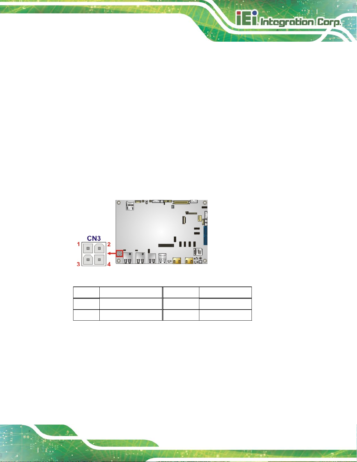
3.2.1 9 V ~ 30 V Power Connector
CN Label: CN3
CN Type:
CN Location:
CN Pinouts:
This connector provides power to the system.
Figure 3-2: 9 V ~ 30 V Power Connector Location
4-pin Molex, p=4.2 mm
See Figure 3-2
See Table 3-3
Pin Description Pin Description
1 GND 2 GND
3 Power (9 V ~ 30 V) 4 Power (9 V ~ 30 V)
Table 3-3: 9 V ~ 30 V Power Connector Pinouts
Page 34

NANO-AL EPIC SBC
Page 20
3.2.2 Audio Connector
CN Label: AUDIO1
CN Type:
CN Location:
CN Pinouts:
This connector connects to speakers, a microphone and an audio input.
Figure 3-3: Audio Connector Location
10-pin header, p=2 mm
See Figure 3-3
See Table 3-4
Pin Description Pin Description
1 LINE_OUTR 2 LINEIN_R
3 ANALOG_GND 4 ANALOG_GND
5 LINE_OUTL 6 LINEIN_L
7 ANALOG_GND 8 ANALOG_GND
9 MICIN1 10 MICIN2
Table 3-4: Audio Connector Pinouts
3.2.3 Backlight Inverter Connector
CN Label: INV1
CN Type:
CN Location:
CN Pinouts:
The backlight inverter connector provides power to an LCD panel.
5-pin wafer, p=2 mm
See Figure 3-4
See Table 3-5
Page 35

NANO-AL EPIC SBC
Page 21
Figure 3-4: Backlight Inverter Connector Location
Pin Description
1 LCD_BKLTCTL
2 GROUND
3 +12V
4 GROUND
5 BACKLIGHT ENABLE
Table 3-5: Backlight Inverter Connector Pinouts
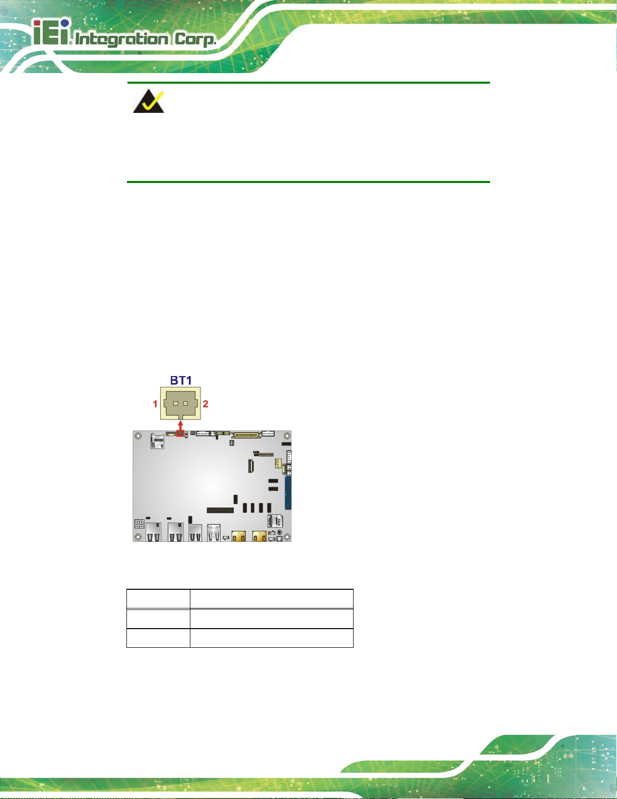
3.2.4 Battery Connector
CAUTION:
Risk of explosion if battery is replaced by an incorrect type. Only
certified engineers should replace the on-board battery.
Dispose of used batteries according to instructions and local regulations.
Page 36
NANO-AL EPIC SBC
Page 22
NOTE:
It is recommended to attach the RTC battery onto the system chassis
in which the NANO-AL is installed.
CN Label: BT1
CN Type:
CN Location:
CN Pinouts:
This is connected to the system battery. The batt ery provide s power to t he system cloc k to
retain the time when power is turned off.
2-pin wafer, p=1.25 mm
See Figure 3-5
See Table 3-6
Figure 3-5: Battery Connector Location
Pin Description
1 VBATT
2 GND
Table 3-6: Battery Connector Pinouts
Page 37

NANO-AL EPIC SBC
Page 23
3.2.5 BIOS Debug Connector
CN Label: 80PORT1
CN Type:
CN Location:
CN Pinouts:
12-pin wafer, p=1 mm
See Figure 3-6
See Table 3-7
This connector is used for BIOS debug.
Figure 3-6: BIOS Debug Connector Location
Pin Description Pin Description
1 KSI0 11 KSO9
2 KSO0 12 KSO10
3 KSO1 13 KSO12
4 KSO2 14 KSI1
5 KSO3 15 KSO11
6 KSO4 16 KSI2
7 KSO5 17 KSI3
8 KSO6 18 GND
9 KSO7 19 GND
10 KSO8 20 GND
Table 3-7: BIOS Debug Connector Pinouts
Page 38
NANO-AL EPIC SBC
Page 24
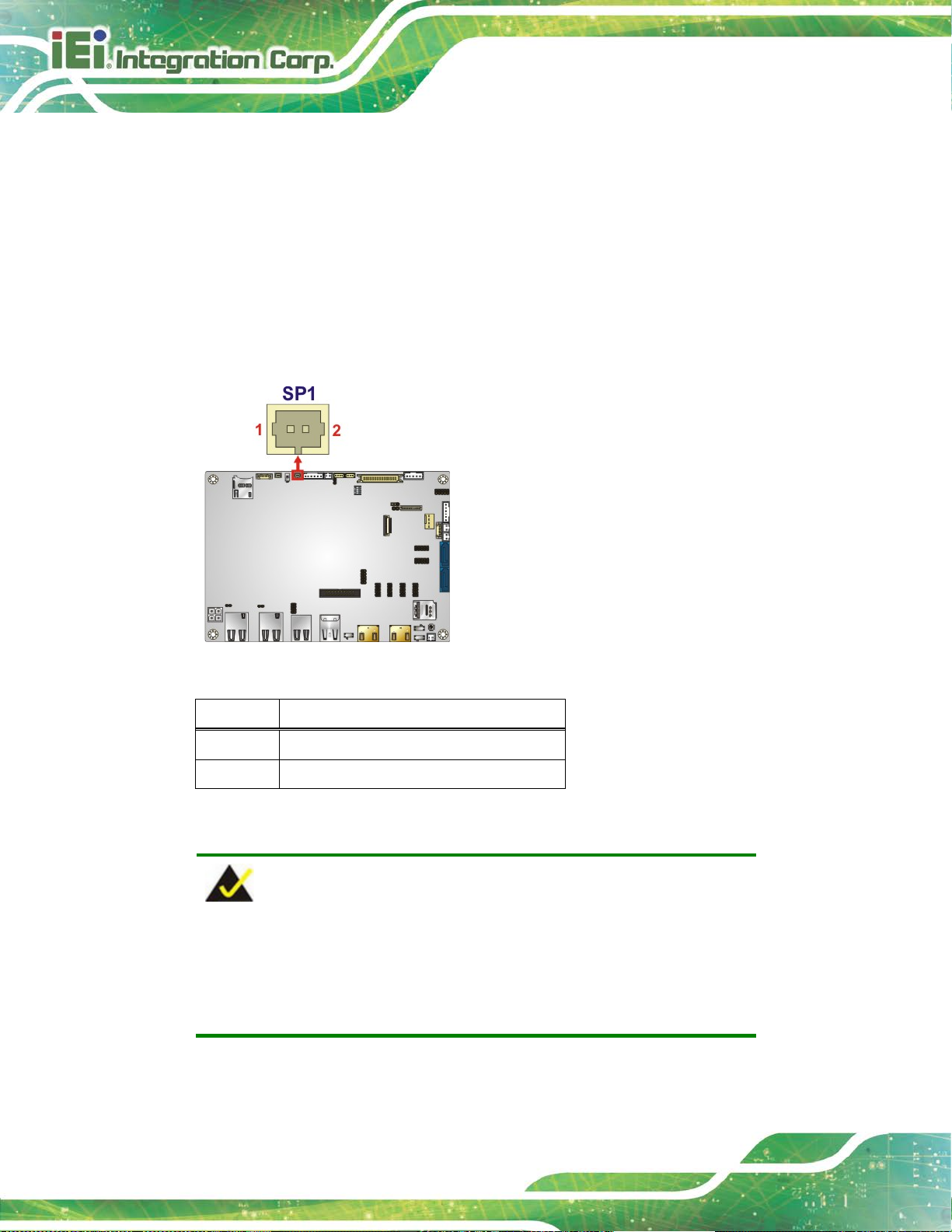
3.2.6 Buzzer Connector
CN Label: SP1
CN Type:
CN Location:
CN Pinouts:
Use this connector to connect a buzzer.
Figure 3-7: Buzzer Connector Location
2-pin wafer, p=1.25 mm
See Figure 3-7
See Table 3-8
Pin Description
1 V5_S
2 GND
Table 3-8: Buzzer Connector Pinouts
NOTE:
If you cannot find a good place to put a buzzer on the NANO-AL, it is
recommended to attach the buzzer onto the system chassis in which
the NANO-AL is installed.
Page 39

NANO-AL EPIC SBC
Page 25
3.2.7 Chassis Intrusion Connector
CN Label: CHASSIS1
CN Type:
CN Location:
CN Pinouts:
The chassis intrusion connector is for a chassis intrusion detection sensor or switch that
detects if a chassis component is removed or repl aced.
Figure 3-8: Chassis Intrusion Connector Location
2-pin header, p=2.54 mm
See Figure 3-8
See Table 3-9
Pin Description
1 CHASSIS OPEN
2 GND
Table 3-9: Chassis Intrusion Connector Pinouts
Page 40

NANO-AL EPIC SBC
Page 26
3.2.8 CPU Fan Connector
CN Label: CPU_FAN1
CN Type:
CN Location:
CN Pinouts:
The fan connector attaches to a CPU cooling fan.
Figure 3-9: CPU Fan Connector Location
4-pin wafer, p=2.54 mm
See Figure 3-9
See Table 3-10
Pin Description
1 GND
2 +12V
3 FANIO
4 PWM
Table 3-10: CPU Fan Connector Pinouts
Page 41

NANO-AL EPIC SBC
Page 27
3.2.9 Digital I/O Connector
CN Label: DIO1
CN Type:
CN Location:
CN Pinouts:
10-pin header, p=2 mm
See Figure 3-10
See Table 3-11
The digital I/O connector provides programmable input and output for external devices.
Figure 3-10: Digital I/O Connector Location
Pin Description Pin Description
1 GND 2 +V5S
3 Output 3 4 Output 2
5 Output 1 6 Output 0
7 Input 3 8 Input 2
9 Input 1 10 Input 0
Table 3-11: Digital I/O Connector Pinouts
Page 42

NANO-AL EPIC SBC
Page 28
3.2.10 EC Debug Connector
CN Label: CN2
CN Type:
CN Location:
CN Pinouts:
20-pin wafer, p=0.5 mm
See Figure 3-11
See Table 3-12
The EC debug connector is used for EC debug.
Figure 3-11: EC Debug Connector Location
Pin Description Pin Description
1 KSI0 11 KSO9
2 KSO0 12 KSO10
3 KSO1 13 KSO12
4 KSO2 14 KSI1
5 KSO3 15 KSO11
6 KSO4 16 KSI2
7 KSO5 17 KSI3
8 KSO6 18 GND
9 KSO7 19 GND
10 KSO8 20 GND
Table 3-12: EC Debug Connector Pinouts
Page 43

NANO-AL EPIC SBC
Page 29
3.2.11 Front Panel Connector
CN Label: CN1
CN Type:
CN Location:
CN Pinouts:
6-pin wafer, p=2 mm
See Figure 3-12
See Table 3-13
The front panel connector connects to the indicator LEDs on the computer's front panel.
Figure 3-12: Front Panel Connector Location
Pin Description
1 VCC
2 GND
3 PWR_LED+
4 PWR_LED5 HDD_LED+
6 HDD_LED-
Table 3-13: Front Panel Connector Pinouts
Page 44

NANO-AL EPIC SBC
Page 30
3.2.12 I2C Connector
CN Label: I2C1
CN Type:
CN Location:
CN Pinouts:
2
C connector is used to connect I2C-bus devices to the motherboard.
The I
4-pin wafer, p=1. 25 m m
See Figure 3-13
See Table 3-14
Figure 3-13: I2C Connector Location
Pin Description
1 GND
2 I2C_DATA
3 I2C_CLK
4 VCC5V
Table 3-14: I2C Connector Pinouts
Page 45
NANO-AL EPIC SBC
Page 31
for detailed
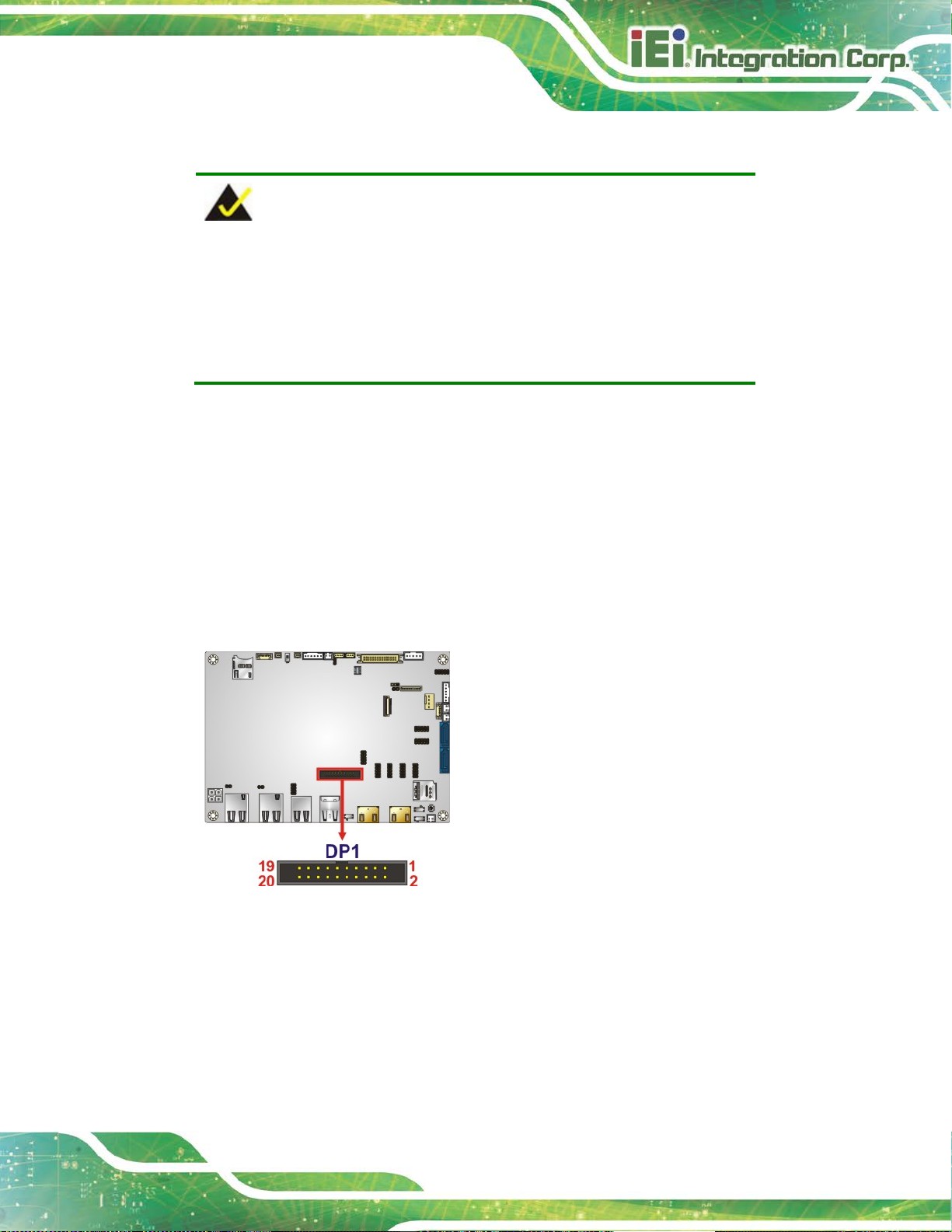
3.2.13 Internal DisplayPort Connector
NOTE:
The user can select either to use the HDMI1 connector or the internal
DisplayPort connector. Use the HDMI1/DP selection switch to
configure the settings. Please refer to Section 4.8.3
information.
CN Label: DP1
CN Type:
CN Location:
CN Pinouts:
The internal DisplayPort connector supports HDMI, LVDS, VGA, DVI and DisplayPort
graphics interfaces.
20-pin box header, p=2.00 mm
See Figure 3-14
See Table 3-15
Figure 3-14: Internal DisplayPort Connector Location
Page 46
NANO-AL EPIC SBC
Page 32
Pin Description Pin Description
1 HPD 2 AUX_P
3 GND 4 AUX_N
5 CAD 6 GND
7 GND 8 LANE2P
9 LANE3P 10 LANE2N
11 LANE3N 12 GND
13 GND 14 LANE0P
15 LANE1P 16 LANE0N
17 LANE1N 18 VCC3V
19 VCC5V 20 NC
Table 3-15: Internal DisplayPort Connector Pinouts
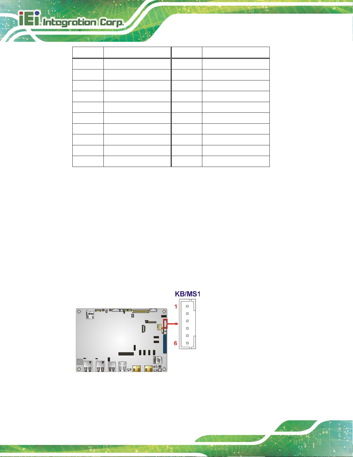
3.2.14 Keyboard and Mouse Connector
CN Label: KB/MS1
CN Type:
CN Location:
CN Pinouts:
6-pin wafer, p=2 mm
See Figure 3-15
See Table 3-16
The keyboard and mouse connector connects to a PS/2 Y-cable that can be connected to
a PS/2 keyboard and mouse.
Figure 3-15: Keyboard and Mouse Connector Location
Page 47
NANO-AL EPIC SBC
Page 33
Pin Description
1 VCC5_KBMS
2 Mouse Data
3 Mouse Clock
4 Keyboard Data
5 Keyboard Clock
6 GND
Table 3-16: Keyboard and Mouse Connector Pinouts
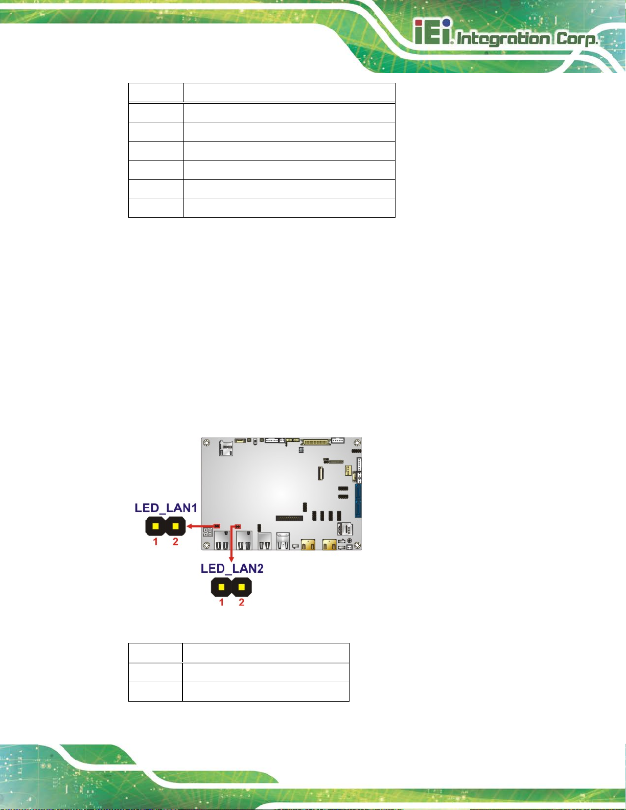
3.2.15 LAN LED Connectors
CN Label: LED_LAN1, LED_LAN2
CN Type:
CN Location:
CN Pinouts:
2-pin header, p=2 mm
See Figure 3-16
See Table 3-17
The LAN LED connectors are used to c onnect t o the LAN LED i ndicators on the chas sis to
indicate users the link activities of the two LAN ports.
Figure 3-16: LAN LED Connector Locations
Pin Description
1 +3.3V
2 LAN1_LED_LNK#_ACT
Table 3-17: LAN LED Connector Pinouts
Page 48

NANO-AL EPIC SBC
Page 34
3.2.16 LVDS Connector
CN Label: LVDS1
CN Type:
CN Location:
CN Pinouts:
40-pin crimp, p=1.25 mm
See Figure 3-17
See Table 3-18
The LVDS connector is for the LCD panel connected to the board.
Figure 3-17: LVDS Connector Location
Pin Description Pin Description
1 GND 2 GND
3 A_Y0# 4 A_Y1#
5 A_Y0 6 A_Y1
7 GND 8 GND
9 A_Y2# 10 A_CK#
11 A_Y2 12 A_CK
13 GND 14 GND
15 A_Y3# 16 B_Y0#
17 A_Y3 18 B_Y0
19 GND 20 GND
21 B_Y1# 22 B_Y2#
23 B_Y1 24 B_Y2
25 GND 26 GND
27 B_CK# 28 B_Y3#
Page 49
NANO-AL EPIC SBC
Page 35
Pin Description Pin Description
29 B_CK 30 B_Y3
31 GND 32 GND
33 GND 34 GND
35 LVDS_VCC 36 LVDS_VCC
37 LVDS_VCC 38 LVDS_VCC
39 LVDS_VCC 40 LVDS_VCC
Table 3-18: LVDS Connector Pinouts
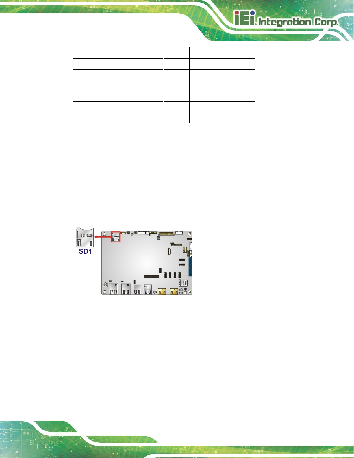
3.2.17 microSD Card Slot (Optional)
CN Label: SD1
CN Type:
CN Location:
microSD card slot
See Figure 3-18
The microSD card slot is for installing a microSD card to the system.
Figure 3-18: microSD Card Slot Location
Page 50

NANO-AL EPIC SBC
Page 36
C position. Please refer to
3.2.18 M.2 Slot
CN Label: M2_1
CN Type:
CN Location:
The M.2 slot is keyed in the B position and provides the mounting screw position for
2242-size M.2 module. The M.2 slot supports the signals of SATA, USB 2.0 and
USB 3.0 (reserved).
M.2 B-key slot
See Figure 3-19
NOTE:
To use the SATA signal of the M.2 slot (M2_1), the user has to set the
M.2 and SATA2 selection switch to B-
Section 4.8.6 for detail information.
Figure 3-19: M.2 Slot Location
Page 51

NANO-AL EPIC SBC
Page 37
3.2.19 PCIe Mini Card Slot
CN Label: MPCIE1
CN Type:
CN Location:
CN Pinouts:
PCIe Mini card slot
See Figure 3-20
See Table 3-19
The PCIe Mini card slot enables a full-size/half-size PCIe Mini card expansion module to
be connected to the board.
Figure 3-20: PCIe Mini Card Slot Location
Pin Description Pin Description
1 PCIE_WAKE# 2 +3.3V
3 N/C 4 GND
5 N/C 6 1.5V
7 N/C 8 +VCC_SIM
9 GND 10 SIM_IO
11 MSATA_CLK# 12 SIM_CLK
13 MSATA _CLK 14 SIM_RST
15 GND 16 SIM_VPP
17 PCIRST# 18 GND
19 N/C 20 +3.3V
Page 52

NANO-AL EPIC SBC
Page 38
Pin Description Pin Description
21 GND 22 PLTRST_N
23 PCIE_RXN 24 +3.3V
25 PCIE_RXP- 26 GND
27 GND 28 1.5V
29 GND 30 SMB_CLK
31 PCIE_TXN 32 SMB_DATA
33 PCIE_TXP 34 GND
35 GND 36 USB_DATA37 GND 38 USB_DATA+
39 +3.3V 40 GND
41 +3.3V 42 N/C
43 +3.3V 44 N/C
45 N/C 46 N/C
47 N/C 48 1.5V
49 N/C 50 GND
51 MSATA_DET 52 +3.3V
Table 3-19: PCIe Mini Card Slot Pinouts
3.2.20 Power Button (On-board)
CN Label: PWR_SW1
CN Type:
CN Location:
Push the on-board power button to power on the NANO-AL.
Push button
See Figure 3-21
Page 53

NANO-AL EPIC SBC
Page 39
Figure 3-21: On-board Power Button Location
3.2.21 Power Button Connector
CN Label: PWR_BTN1
CN Type:
CN Location:
CN Pinouts:
The power button connector connects to the power button on the computer's front panel.
Figure 3-22: Power Button Connector Location
2-pin wafer, p=2 mm
See Figure 3-22
See Table 3-20
Pin Description
1 PWR_BTN+
2 PWR_BTN-
Table 3-20: Power Button Connector Pinouts
Page 54

NANO-AL EPIC SBC
Page 40
3.2.22 Reset Button Connector
CN Label: RST_BTN1
CN Type:
CN Location:
CN Pinouts:
The reset button connector connects to the reset button on the computer's front panel.
Figure 3-23: Reset Button Connector Location
2-pin wafer, p=2 mm
See Figure 3-23
See Table 3-21
Pin Description
1 RESET+
2 RESET-
Table 3-21: Reset Button Connector Pinouts
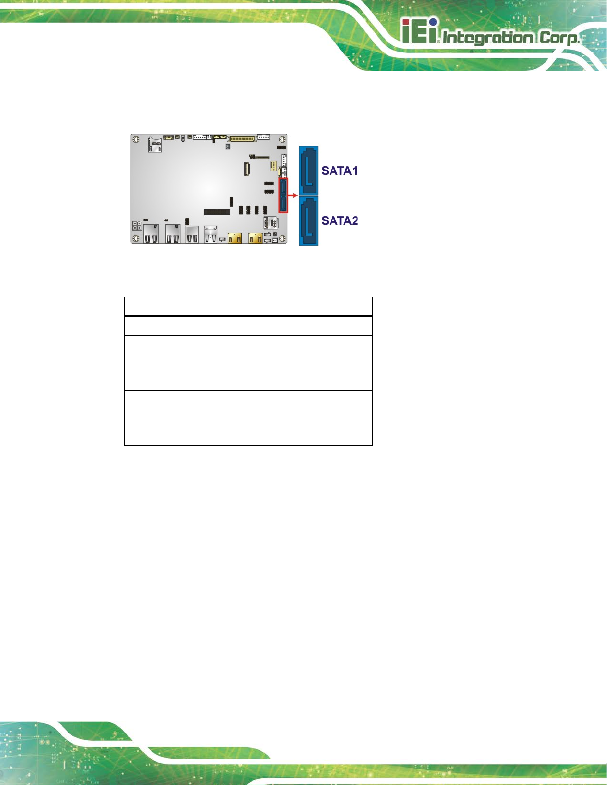
3.2.23 SATA 6Gb/s Drive Connectors
CN Label: SATA1, SATA2
CN Type:
CN Location:
CN Pinouts:
7-pin SATA connector
See Figure 3-24
See Table 3-22
Page 55
NANO-AL EPIC SBC
Page 41
The SATA drive connectors can be connected to SATA drives and support up to 6Gb/s
data transfer rate.
Figure 3-24: SATA 6Gb/s Drive Connector Locations
Pin Description
1 GND
2 SATA_TX+
3 SATA_TX4 GND
5 SATA_RX6 SATA_RX+
7 GND
Table 3-22: SATA 6Gb/s Drive Connector Pinouts
3.2.24 SATA Power Connectors (5 V)
CN Label: SATAPWR1, SATAPWR2
CN Type:
CN Location:
CN Pinouts:
Use the SATA power connector to connect to SATA device power connections.
2-pin wafer, p=2 mm
See Figure 3-25
See Table 3-23
Page 56

NANO-AL EPIC SBC
Page 42
Figure 3-25: 5 V SATA Power Connector Locations
Pin Description
1 +V5S
2 GND
Table 3-23: 5 V SATA Power Connector Pinouts
3.2.25 Serial Port Connector, RS-232
CN Label: COM1, COM2, COM3, COM4
CN Type:
CN Location:
CN Pinouts:
The 10-pin serial port connector provides one RS-232 serial communications channel.
10-pin header, p=2 mm
See Figure 3-26
See Table 3-24
Figure 3-26: RS-232 Serial Port Connector Locations
Page 57

NANO-AL EPIC SBC
Page 43
Pin Description Pin Description
1 DCD 2 DSR
3 RXD 4 RTS
5 TXD 6 CTS
7 DTR 8 RI
9 GND 10 GND
Table 3-24: RS-232 Serial Port Connector Pinouts
3.2.26 Serial Port Connector, RS-232/422/485
CN Label: COM5, COM6
CN Type:
CN Location:
CN Pinouts:
10-pin header, p=2 mm
See Figure 3-27
See Table 3-25
This connector provides RS-232, RS-422 or RS-485 communications.
Each of these connectors provides RS-232/422/485 connections.
NOTE:
The communication protocol of the serial ports is set through the BIOS menu
in “Advanced Super IO Configuration Serial Port 5/6 Configuration”. Use
the Transfer Mode BIOS option to configure the correspondent serial ports
(refer to Sections 5.3.3.1.5 and 5.3.3.1.6 for detailed information).
Page 58

NANO-AL EPIC SBC
Page 44
Figure 3-27: RS-232/422/485 Serial Port Connector Locati ons
Pin Description Pin Description
1 DCD 2 DSR
3 RXD 4 RTS
5 TXD 6 CTS
7 DTR 8 RI
9 GND 10 GND
Table 3-25: RS-232/422/485 Serial Port Connector Pinouts
Use the optional RS-422/485 cable to connect to a serial device. The pinouts of the DB-9
connector are listed below.
RS-232 Pinouts RS-422 Pinouts RS-485 Pinouts
Table 3-26: DB-9 RS-232/422/485 Pinouts
Page 59

NANO-AL EPIC SBC
Page 45
3.2.27 SIM Card Slot (Optional)
CN Label: SIM1
CN Type:
CN Location:
The SIM card slot accepts a SIM card for 3G network communication.
Figure 3-28: SIM Card Slot Location
SIM card slot
See Figure 3-28
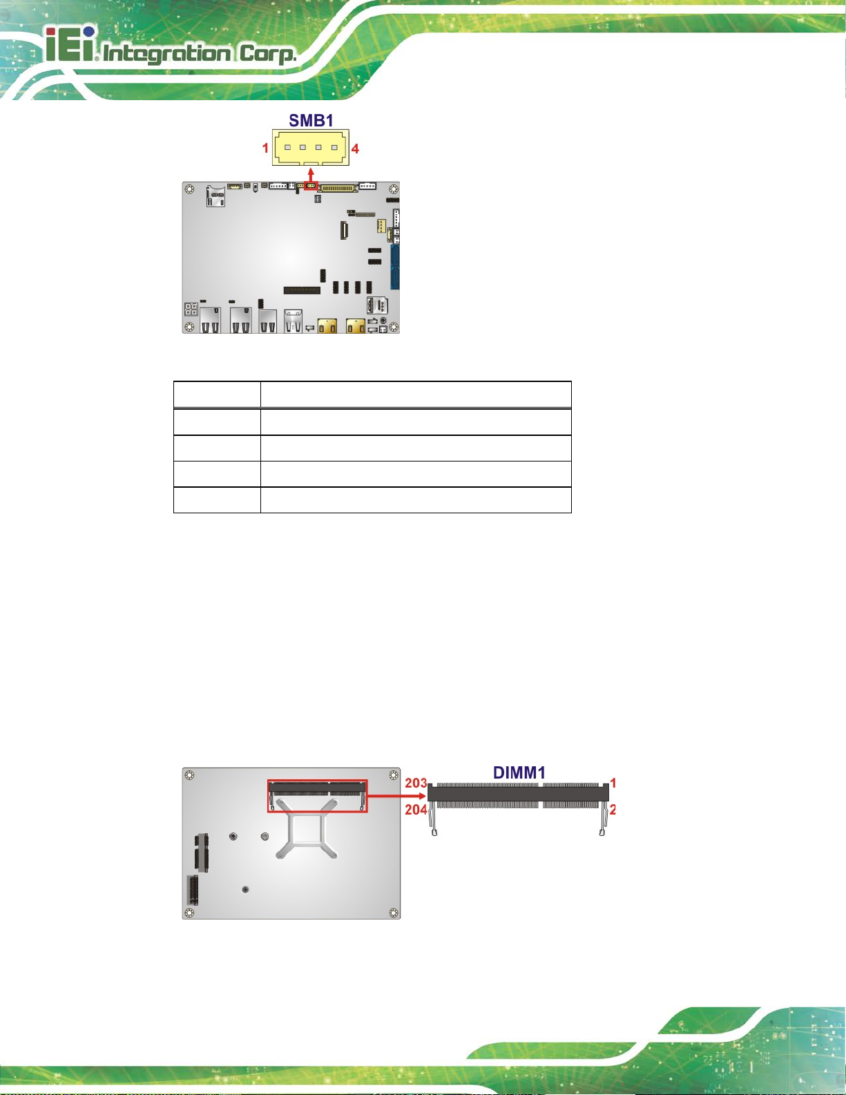
3.2.28 SMBus Connector
CN Label: SMB1
CN Type:
CN Location:
CN Pinouts:
The SMBus (System Management Bus) connector provides low-speed system
management communications.
4-pin wafer, p=1.25 mm
See Figure 3-29
See Table 3-27
Page 60
NANO-AL EPIC SBC
Page 46
Figure 3-29: SMBus Connector Location
Pin Description
1 GND
2 SMB_DATA
3 SMB_CLK
4 +V5S
Table 3-27: SMBus Connector Pinouts
3.2.29 SO-DIMM Connector
CN Label: DIMM1
CN Type:
CN Location:
The SO-DIMM connector is for installing a DDR3L SO-DIMM on the system.
204-pin DDR3L SO-DIMM connector
See Figure 3-30
Figure 3-30: SO-DIMM Connector Location
Page 61
NANO-AL EPIC SBC
Page 47
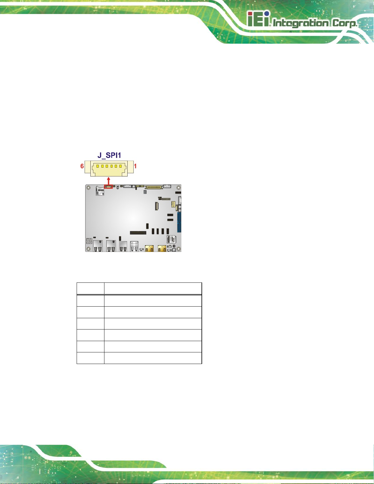
3.2.30 SPI Flash Connector
CN Label: J_SPI1
CN Type:
CN Location:
CN Pinouts:
6-pin wafer, p=1.25 mm
See Figure 3-31
See Table 3-28
The SPI flash connector is used to flash the SPI ROM.
Figure 3-31: SPI Flash Connector Location
Pin Description
1 +V3.3M_SPI_CON
2 SPI_CS
3 SPI_SO_SW
4 SPI_CLK_SW
5 SPI_SI_SW
6 GND
Table 3-28: SPI Flash Connector Pinouts
Page 62

NANO-AL EPIC SBC
Page 48
3.2.31 SPI Flash Connector (EC)
CN Label: J_SPI2
CN Type:
CN Location:
CN Pinouts:
6-pin wafer, p=1.25 mm
See Figure 3-32
See Table 3-29
The SPI flash connector is used to flash the EC ROM.
Figure 3-32: EC SPI Flash Connector Location
Pin Description
1 +V3.3M_SPI_CON_EC
2 SPI_CS_EC
3 SPI_SO_SW_EC
4 SPI_CLK_SW_EC
5 SPI_SI_SW_EC
6 GND
Table 3-29: EC SPI Flash Connector Pinouts
3.2.32 USB 2.0 Connector
CN Label: USB2-2
CN Type:
CN Location:
CN Pinouts:
8-pin header, p=2 mm
See Figure 3-33
See Table 3-30
Page 63

NANO-AL EPIC SBC
Page 49
The USB header can connect to two USB 2.0 devices.
Figure 3-33: USB 2.0 Connector Location
Pin Description Pin Description
1 VCC 2 GND
3 DATA- 4 DATA+
5 DATA+ 6 DATA7 GND 8 VCC
Table 3-30: USB 2.0 Connector Pinouts
3.3 External Interface Connectors
The figure below shows the external peripheral interface connector (EPIC) panel. The
EPIC panel consists of the following:
Figure 3-34: External Interface Connectors
Page 64

NANO-AL EPIC SBC
Page 50
3.3.1 HDMI Connectors
CN Label: HDMI1, HDMI2
CN Type:
CN Location:
CN Pinouts:
HDMI connector
See Figure 3-34
See Table 3-31
The HDMI connectors can connect to HDMI devices.
Pin Description Pin Description
1 HDMI_DATA2 2 GND
3 HDMI_DATA2# 4 HDMI_DATA1
5 GND 6 HDMI_DATA1#
7 HDMI_DATA0 8 GND
9 HDMI_DATA0# 10 HDMI_CLK
11 GND 12 HDMI_ CLK#
13 N/C 14 N/C
15 HDMI_SCL 16 HDMI_SDA
17 GND 18 +5V
19 HDMI_HPD 20 HDMI_GND
21 HDMI_GND 22 HDMI_GND
23 HDMI_GND
Table 3-31: HDMI Connector Pinouts
Figure 3-35: HDMI Connector Pinout Locations
Page 65

NANO-AL EPIC SBC
Page 51
connector is enabled, the HDMI1 connector will be disabled. This is
NOTE:
The HDMI1 connector is co-lay with the iDP connector. When the iDP
controlled by the HDMI/DP selection switch. Please refer to Section
4.8.3 for detailed information.
3.3.2 LAN Connectors
CN Label: LAN1, LAN2
CN Type:
CN Location:
CN Pinouts:
The LAN connector connects to a local network.
Figure 3-36: LAN Connector
Pin Description Pin Description
1 TRD0+ 5 TRD2+
2 TRD0- 6 TRD2-
RJ-45
See Figure 3-34
See Figure 3-36 and Table 3-32
3 TRD1+ 7 TRD3+
4 TRD1- 8 TRD3-
Table 3-32: LAN Pinouts
Page 66

NANO-AL EPIC SBC
Page 52
3.3.3 USB 2.0 Connectors
CN Label: USB2-1
CN Type:
CN Location:
CN Pinouts:
USB 2.0 port
See Figure 3-34
See Table 3-33
The USB 2.0 connector can be connected to a USB 2.0/1.1 device.
Pin Description
1 VCC
2 DATA3 DATA+
4 GND
Table 3-33: USB 2.0 Port Pinouts
3.3.4 USB 3.0 Connectors
CN Label: USB3-1
CN Type:
CN Location:
CN Pinouts:
USB 3.0 port
See Figure 3-34
Table 3-34
See
The USB 3.0 connectors can be connected to a USB 2.0 or USB 3.0 device. The pinouts
of USB 3.0 connectors are shown below.
Pin Description Pin Description
1 +5V 2 USB2P03 USB2P0+ 4 GND
5 USB3P0_RXDN1 6 USB3P0_RXDP1
7 GND 8 USB3P0_TXDN1
9 USB3P0_TXDP1
Table 3-34: USB 3.0 Port Pinouts
Page 67

NANO-AL EPIC SBC
Page 53
Chapter
4
4 Installation
Page 68

NANO-AL EPIC SBC
Page 54
Failure to take ESD precautions during installation may result in
is installed. All
4.1 Anti-static Precautions
WARNING:
permanent damage to the product and severe injury to the user.
Electrostatic discharge (ESD) can cause serious damage to electronic components,
including the NANO-AL. Dry climates are especially susceptible to ESD. It is therefore
critical to strictly adhere to the following a nti-static prec autions when ever the NANO-AL, or
any other electrical component, is handled.
Wear an anti-static wristband: - Wearing a simple anti-static wristband ca n
help to prevent ESD from damaging the board.
Self-grounding:- Before handling the board touch any grounded conducting
material. During the time the board is handled, f requently touch any
conducting materials that are connected to the ground.
Use an anti-static pad: When configuring the NANO-AL, place it on an
anti-static pad. This reduces the possibility of ESD damaging the NANO-AL.
Only handle the edges of the PCB:-: When handling the PCB, hold it by the
edges.
4.2 Installation Considerations
NOTE:
The following installation notices and installation considerations should
be read and understood before the NANO-AL
installation notices pertaining to the installation of NANO-AL should be
strictly adhered to. Failing to adhere to these precautions may lead to
severe damage of the NANO-AL and injury to the person installing the
motherboard.
Page 69

NANO-AL EPIC SBC
Page 55
ld be
WARNING:
The installation instructions described in this manual shou
carefully followed in order to prevent damage to the NANO-AL,
NANO-AL components and injury to the user.
Before and during the installation please DO the following:
Read the user manual:
o The user manual provides a complete description of the installation
instructions and configuration options.
Wear an electrostatic discharge cuff (ESD):
o Electronic components are easily damaged by ESD. Wearing an ES D cuff
removes ESD from the body and helps prevent ESD damage.
Place on an anti-static pad:
o When installing or configuring the motherboard, place it on an anti-static
pad. This helps to prevent potential ESD damage.
Turn all power off:
o Make sure the product is disconnected from all power supplies and that
no electricity is being fed into the system.
Before and during the installation of the NANO-AL, DO NOT:
Remove any of the stickers on the PCB board. T hese sti ckers are r equired f or
warranty validation.
Use the product before verifying all the cables and power connectors are
properly connected.
Allow screws to come in contact with the PCB circuit, connector pins, or its
components.
Page 70

NANO-AL EPIC SBC
Page 56
4.3 SO-DIMM Installation
To install a SO-DIMM, please follow the steps below and refer to Figure 4-1.
NOTE:
Use DIMM1 slot when installing one SO-DIMM. For the SO-DIMM slot
location, refer to Figure 3-30.
Figure 4-1: SO-DIMM Installation
Step 1: Locate the SO-DIMM socket on the solder side of the NANO-AL. Place the
board on an anti-static mat.
Step 2: Align the SO-DIMM with the socket. Align the notch on the memory with t he
notch on the memory socket.
Step 3: Insert the SO-DIMM. Push the memory in at a 20º angle. (See Figure 4-1)
Step 4: Seat the SO-DIMM. Gently push downwards and the arms clip into place. (See
Figure 4-1) Step 0:
4.4 Full-size PCIe Mini Card Installation
The PCIe Mini card slot allows installation of either a full-size or half-size PCIe Mini card.
To install a full-size PCIe Mini card, please follow the steps below.
Step 1: Locate the PCIe Mini card slot. See Chapter 3.
Page 71

NANO-AL EPIC SBC
Page 57
Figure 4-3: Inserting the Full-size PCIe Mini Card into the Slot at an Angle
Step 2: Remove the retention screw. Remove the retention screw as shown in
Figure 4-2.
Figure 4-2: Removing the Retention Screw
Step 3: Insert into the socket at an angle. Line up the notch o n the card with the notch on
the slot. Slide the PCI e Mini card into the sock et at an angle of about 2 0º (Figure 4-3).
Page 72

NANO-AL EPIC SBC
Page 58
Step 4: Secure the full-size PCIe Mini card. Secure the full-size PCIe Mini card with
the retention screw previously removed (Figure 4-4). Step 0:
Figure 4-4: Securing the Full-size PCIe Mini Card
4.5 Half-size PCIe Mini Card Installation
The PCIe Mini card slot allows installation of either a full-size or half-size PCIe Mini card.
To install a half-size PCIe Mini card, please follow the steps below.
Step 1: Locate the PCIe Mini card slot. See Chapter 3.
Step 2: Install the standoff to the screw hole for the half-size PCIe Mini card. Install
the supplied standoff to the screw hole for the half-si ze P CI e M i ni card
(Figure 4-5).
Page 73

NANO-AL EPIC SBC
Page 59
Figure 4-5: Installing the Standoff
Step 3: Insert into the socket at an angle. Line up the notch on the card wit h the notch on
the slot. Slide the PCIe Mini card into th e slot at a n angl e of a bout 2 0º (Figure 4-6).
Figure 4-6: Inserting the Half-size PCIe Mini Card into the Slot at an Angle
Step 4: Secure the half-size PCIe Mini card. Secure the half-size PCIe Mini card with
the supplied retention screw (Figure 4-7). Step 0:
Page 74

NANO-AL EPIC SBC
Page 60
C position. Please refer to
Figure 4-7: Securing the Half-size PCIe Mini Card
4.6 M.2 Module Installation
NOTE:
To use the SATA signal of the M.2 slot (M2_1), the user has to set the
M.2 and SATA2 selection switch to BSection 4.8.6 for detail information.
To install an M.2 module, please follow the steps below.
Step 1: Locate the M.2 module slot. See Chapter 3.
Page 75

NANO-AL EPIC SBC
Page 61
Step 2: Remove the on-board retention screw as shown in Figure 4-8.
Figure 4-8: Removing the M.2 Module Retention Screw
Step 3: Line up the notch on the card with the notch on the slot. Slide the M.2 module
into the socket at an angle of about 20º (Figure 4-9).
Figure 4-9: Inserting the M.2 Module into the Slot at an Angle
Page 76
NANO-AL EPIC SBC
Page 62
Step 4: Push the M.2 module down and secure it with the previously removed retention
screw (Figure 4-10). Step 0:
Figure 4-10: Securing the M.2 Module
4.7 SIM Card Installation
To install a SIM card, please follow the steps below.
Step 1: Locate the SIM card slot. See Chapter 3.
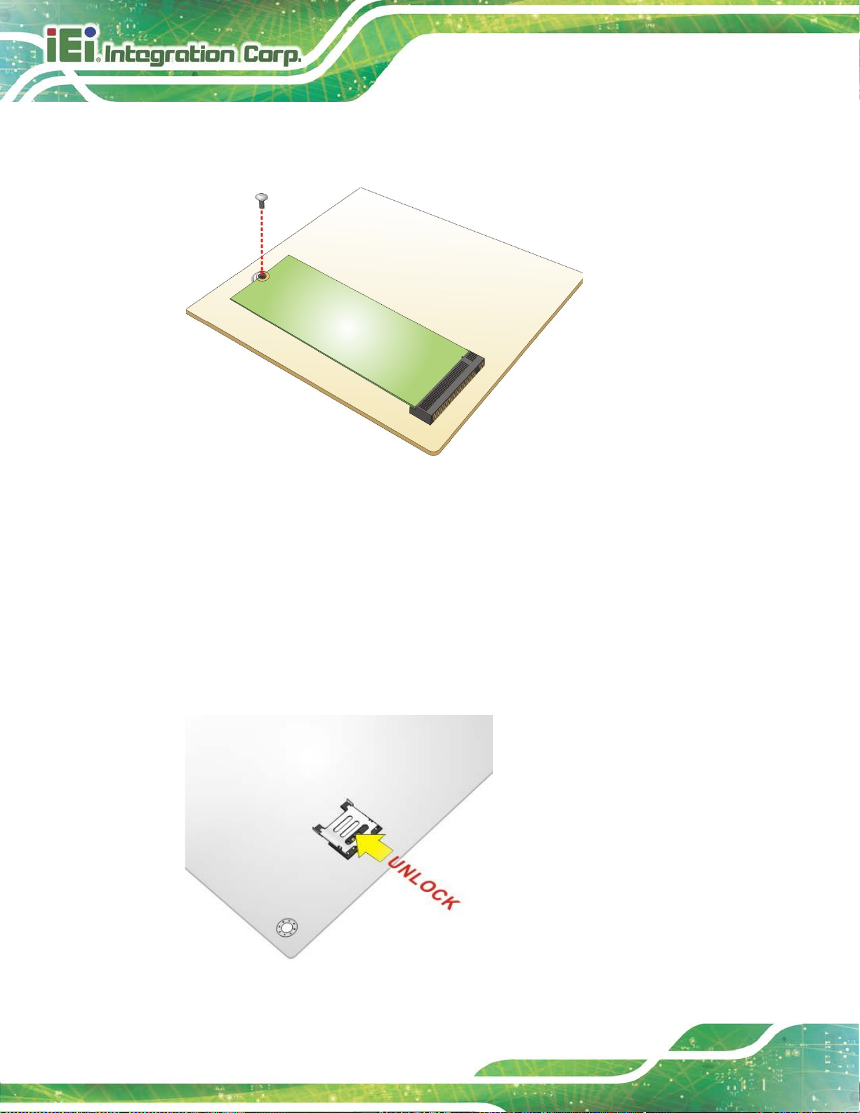
Step 2: Unlock the SIM card slot cover by sliding the cover in the direction as shown by
the arrow in Figure 4-11.
Figure 4-11: Unlock SIM Card Slot Cover
Page 77

NANO-AL EPIC SBC
Page 63
Step 3: Open the slot cover and place a SIM card onto the slot. The cut mark on the
corner should be facing away from the slot as shown in Figure 4-12.
Figure 4-12: SIM Card Installation
Step 4: Close the slot cover and lock it by sliding it in the direction as shown by the
arrow in Figure 4-13. Step 0:
Figure 4-13: Lock SIM Card Slot Cover
Page 78

NANO-AL EPIC SBC
Page 64
4.8 System Configuration
The system configuration is controlled by buttons/jumpers/switches, and should be
performed before installation.
4.8.1 AT/ATX Power Mode Selection
The AT and ATX power mode selection is made through the AT/ATX power mod e swi tch
which is shown in Figure 4-14.
Figure 4-14: AT/ATX Power Mode Switch Location
Setting Description
A-B ATX power mode (default)
B-C AT power mode
Table 4-1: AT/ATX Power Mode Switch Settings
Page 79

NANO-AL EPIC SBC
Page 65
4.8.2 Clear CMOS Button
To reset the BIOS, remove the on-board battery and press the clear CMOS button for
three seconds or more. The clear CMOS button location is shown in Figure 4-15.
Figure 4-15: Clear CMOS Button Location
4.8.3 HDMI/DP Selection Switch
CN Label: J_HDMI_DP1
CN Type:
CN Location:
CN Settings:
Use the HDMI/DP selection switch to disable or enable the HDMI1 connector since the
iDP connector (DP1) is co-lay with the HDMI1 connector. HDMI/DP selection switch
settings are shown in Table 4-2.
Setting Description
A-B Enable HDMI1 and disable internal DisplayPort (DP1) (Default)
B-C Enable internal DisplayPort (DP1) and disable HDMI1
Table 4-2: HDMI/DP Selection Switch Settings
The location of the HDMI/DP selection switch is shown in Figure 4-16.
Switch
See Figure 4-16
See Table 4-2
Page 80

NANO-AL EPIC SBC
Page 66
Figure 4-16: HDMI/DP Selection Switch Location
4.8.4 LVDS Panel Type Selection
Jumper Label: SW1
Jumper Type:
Jumper Settings:
Jumper Location:
Use the DIP switch to select the resolution of the LCD panel connected to the LVDS
connector.
DIP switch
See Table 4-3
See Figure 4-17
Page 81

NANO-AL EPIC SBC
Page 67
* ON=0, OFF=1
SW1 (4-3-2-1) Description
0000 800x600 18-bit (default)
0001 1024x768 18-bit
0010 1024x768 24-bit
0011 1280x768 18-bit
0100 1280x800 18-bit
0101 1280x960 18-bit
0110 1280x1024 48-bit
0111 1366x768 18-bit
1000 1366x768 24-bit
1001 1440x960 48-bit
1010 1400x1050 48-bit
1011 1600x900 48-bit
1100 1680x1050 48-bit
1101 1600x1200 48-bit
1110 1920x1080 48-bit
1111 1920x1200 48-bit
Table 4-3: LVDS Panel Type Selection
Figure 4-17: LVDS Panel Type Selection Switch Location
Page 82

NANO-AL EPIC SBC
Page 68
may occur if the
wrong voltage is selected with this jumper. Please refer to the user
4.8.5 LVDS Voltage Selection
WARNING:
Permanent damage to the screen and NANO-AL
guide that came with the monitor to select the correct voltage.
Jumper Label: JP1
Jumper Type:
Jumper Settings:
Jumper Location:
The LVDS voltage selection jumper allows setting the voltage provided to the monitor
connected to the LVDS connector.
Setting Description
Short 1-2 +3.3V LVDS (Default)
Short 2-3 +5V LVDS
Table 4-4: LVDS Voltage Selection Jumper Settings
3-pin header
See Table 4-4
See Figure 4-18
Figure 4-18: LVDS Voltage Selection Jumper Location
Page 83

NANO-AL EPIC SBC
Page 69
4.8.6 M.2 and SATA2 Selection Switch
To use the SATA signal of the M.2 slot (M2_1), the user has to set this switch to B-C
position. The M.2 and SATA2 selection switch settings are shown in Table 4-5.
Setting Description
A-B
B-C
SATA2 is enabled and M.2 SATA signal is
disabled (Default)
M.2 SATA signal is enabled to be used and
SATA2 is disabled.
Table 4-5: M.2 and SATA2 Selection Switch Settings
The location of the M.2 and SATA2 selection switch is shown in Figure 4-19 below.
Figure 4-19: M.2 and SATA2 Selection Switch Location
Page 84
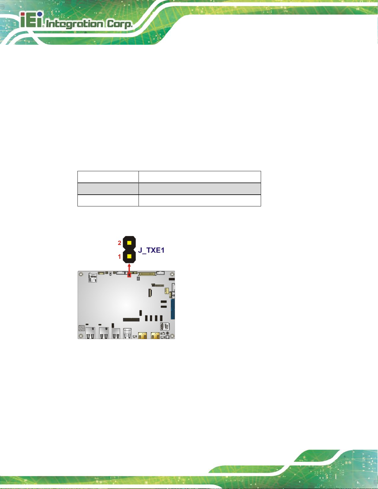
NANO-AL EPIC SBC
Page 70
4.8.7 Flash Descriptor Security Override Jumper
CN Label: J_TXE1
CN Type:
CN Location:
CN Settings:
The Flash Descriptor Security Override jumper (ME_FLASH1) allows to enable or disable
the ME firmware update. Refer to Figure 4-19 and Table 4-5 for the jumper location and
settings.
Setting Description
Open Disabled (default)
Short Enabled
Table 4-6: Flash Descriptor Security Override Jumper Settings
2-pin header, p=2 mm
See Figure 4-20
See Table 4-6
Figure 4-20: Flash Descriptor Security Override Jumper Location
To update the ME firmware, please follow the steps below.
Step 1: Before turning on the system power, short the Flash Descriptor Security
Override jumper.
Step 2: Update the BIOS and ME firmware, and then turn off the system power.
Page 85

NANO-AL EPIC SBC
Page 71
within recommended
Step 3: Remove the metal clip on the Flash Descriptor Security Override jumper.
Step 4: Restart the system. The system will reboot 2 ~ 3 times to complete the ME
firmware update.Step 0:
4.9 Chassis Installation
4.9.1 Airflow
WARNING:
Airflow is critical for keeping components
operating temperatures. The chassis should have fans and vents as
necessary to keep things cool.
The NANO-AL must be installed in a chassis with ventilation holes on the sides allowing
airflow to travel through the heat sink surf ace. In a system with an individual power supply
unit, the cooling fan of a power supply can also help generate airflow through the board
surface.
4.9.2 Motherboard Installation
To install the NANO-AL motherboard into the chassis please refer to the reference
material that came with the chassis.
Page 86

NANO-AL EPIC SBC
Page 72
4.10 Internal Peripheral Device Connections
This section outlines the installation of peripheral devices to the onboard connectors.
4.10.1 RS-232 Cable Connection
The single RS-232 cable consists of one serial port connector attached to a serial
communications cable that is then attached to a D-sub 9 male connector. To install the
single RS-232 cable, please follow the steps below.
Step 1: Locate the connector. The location of the RS-232 connector is shown in
Chapter 3.
Step 2: Insert the cable connector. A l ign the cable connector with the onboard
connector. Make sure pin 1 on the board and connector l i ne up. Pin 1 on the
cable connector is indicated with a white dot. See Figure 4-21.
Figure 4-21: Single RS-232 Cable Installation
Step 3: Secure the bracket. The single RS-232 connector has two retention screws
that must be secured to a chassis or bracket.
Page 87

NANO-AL EPIC SBC
Page 73
Step 4: Connect the serial device. Once the single RS-232 connector is connected to
a chassis or bracket, a serial communications d evice can be connected to the
system. Step 0:
4.10.2 SATA Drive Connection
The NANO-AL is shipped with two SATA drive cables. To connect the SATA drive to the
connector, please follow the steps below.
Step 1: Locate the SATA connector and the SATA p o wer connector. The locatio ns of
the connectors are shown in Chapter 3.
Step 2: Insert the cable connector. Insert the cable connector into the on-board SATA
drive connector and the SATA power connector. See Figure 4-22.
Figure 4-22: SATA Drive Cable Connection
Step 3: Connect the cable to the SATA disk. Connect the connector on the other end
of the cable to the connector at the back of t he SATA drive. See Figure 4-22.
Step 4: To remove th e SATA cable from the SATA connector, press the clip on the
connector at the end of the cable. Step 0:
Page 88

NANO-AL EPIC SBC
Page 74
Figure 4-23: IEI Resource Download Center
4.11 Software Installation
All the drivers for the NANO-AL are available on IEI Resource Download Center
(https://download.ieiworld.com
software, utilities, and documentation.
). Type NANO-AL and press Enter to find all the relevant
IEI provides the following drivers for Windows 7, Windows 8 and Windows 10 operating
systems.
Chipset
VGA (Windows 10 only)
LAN
Audio
Intel
TXE
®
Serial IO (Windows 10 64-bit OS only)
Page 89

NANO-AL EPIC SBC
Page 75
4.11.1 Driver Download
To download drivers from IEI Resource Download Center, follow the steps below.
Step 1: Go to https://download.ieiworld.com
Step 2: All product-related software, utilities, and documentation will be listed. You can
choose Driver to filter the result.
Step 3: Click the driver file name on the page and you will be prompted with the
. Type NANO-AL and pre ss Enter.
following window. You can download the entire ISO file (
arrow to find an individual driver and click the file name to download (
), or click the small
).
Page 90

NANO-AL EPIC SBC
Page 76
NOTE:
To install software from the downloaded ISO image file in Windows 8,
8.1 or 10, double-click the ISO file to mount it as a virtual drive to view
its content. On Windows 7 system, an additional tool (such as Virtual
CD-ROM Control Panel from Microsoft) i s needed to mount the file.
Page 91

NANO-AL EPIC SBC
Page 77
Chapter
5
5 BIOS
Page 92
NANO-AL EPIC SBC
Page 78
Some of the BIOS options may vary throughout the life cycle of the
5.1 Introduction
The BIOS is programmed onto the BIOS chip. The BI OS setup pro gram allows chang es to
certain system settings. This chapter outli nes t he options that can be changed.
NOTE:
product and are subject to change without prior notice.
5.1.1 Starting Setup
The UEFI BIOS is activated when the computer is turned on. The setup program can be
activated by pressing the DEL or F2 key as soon as the system is turned on.
If the system enters the OS environment before the DEL or F2 key is pressed, restart the
computer and try again.
5.1.2 Using Setup
Use the arrow keys to highlight items, press ENTER to select, use the PageUp and
PageDown keys to change entries, press F1 for help and press E
keys are shown in the following table.
Key Function
Up arrow Move to previous item
Down arrow Move to next item
Left arrow Move to the item on the left hand side
Right arrow Move to the item on the right hand side
+ Increase the numeric value or make changes
- Decrease the numeric value or make changes
SC to quit. Navigation
Esc key Main Menu – Quit and not save changes into CMOS
Status Page Setup Menu and Option Page Setup Menu -Exit current page and return to Main Menu
Page 93

NANO-AL EPIC SBC
Page 79
Key Function
F1 General help, only for Status Page Setup Menu and Opt ion
F2 Load previous values
F3 Load optimized defaults
F4 Save changes and Exit BIOS
Table 5-1: BIOS Navigation Keys
5.1.3 Getting Help
When F1 is pressed a small help window describing the appropriate keys to use and the
Page Setup Menu
possible selections for the highlighted item appears. To ex it the Help Window press E
the F1 key again.
5.1.4 Unable to Reboot after Configuration Changes
If the computer cannot boot after changes to the system configuration are made, CMOS
defaults. Use the clear CMOS button described in Section 4.8.2.
5.1.5 BIOS Menu Bar
The menu bar on top of the BIOS screen has the foll owing main items:
Main – Changes the basic system configuration.
Advanced – Changes the advanced system settings.
Chipset – Changes the chipset settings.
Security – Sets User and Supervisor Passwords.
Boot – Changes the system boot configuration.
Save & Exit – Selects exit options and loads default settings.
SC or
The following sections completely describe the configuration options found in the menu
items at the top of the BIOS screen and listed above.
Page 94

NANO-AL EPIC SBC
Page 80
Aptio Setup Utility – Copyright (C) 2017 American Megatrends, Inc.
Main
Advanced
Chipset
Security
Boot
Save & Exit
Version 2.18.1263. Copyright (C) 2017 American Megatrends, Inc.
5.2 Main
The Main BIOS menu (BIOS Menu 1) appears when the BIOS Setup program is entered.
The Main menu gives an overview of the basic syste m i nformation.
BIOS Information
BIOS Vendor American Megatrends
Core Version 5.12
Compliancy UEFI 2.5; PI 1.4
Project Version E428AR10b.BIN
Build Date and Time 02/16/2017 16:31:47
iWDD Vendor iEi
iWDD Version E4280222.bin
Platform firmware Information
BXT SOC B1
MRC Version 0.56
PUNIT FW 20
PMC FW 03.26
TXE FW 3.0.12.1138
ISH FW 4.1.0.3364
GOP 0.0.0036
Memory Information
Total Memory 4096 MB
Memory Speed 1600 MHz
Access Level Administrator
System Date [Tue 03/21/2017]
System Time [15:10:27]
Set the Date. Use Tab to
switch between Date
elements.
---------------------
: Select Screen
↑ ↓: Select Item
Enter: Select
+/-: Change Opt.
F1: General Help
F2: Previous Values
F3: Optimized Defaults
F4: Save & Exit
ESC: Exit
BIOS Menu 1: Main
The Main menu has two user configurable fields:
System Date [xx/xx/xx]
Use the System Date option to set the sy stem date. Manuall y enter the day, mont h and year.
System Time [xx:xx:xx]
Use the System Time option to set the system time. Manually enter the hours, minutes
and seconds.
Page 95

NANO-AL EPIC SBC
Page 81
Aptio Setup Utility – Copyright (C) 2017 American Megatrends, Inc.
Main
Advanced
Chipset
Security
Boot
Save & Exit
Version 2.18.1263. Copyright (C) 2017 American Megatrends, Inc.
5.3 Advanced
Use the Advanced menu (BIOS Menu 2) to configure the CPU and peripheral devices
through the following sub-menus:
WARNING:
Setting the wrong values in the sections below may cause the system
to malfunction. Make sure that the settings made are compatible with
the hardware.
> Trusted Computing
> ACPI Settings
> F81866 Super IO Configuration
> iWDD H/W Monitor
> USB Configuration
> CPU Configuration
> RTC Wake Settings
> Power Saving Configuration
> Serial Port Console Redirection
> iEi Feature
BIOS Menu 2: Advanced
Trusted Computing
Settings
----------------------
: Select Screen
↑ ↓: Select Item
Enter: Select
+/-: Change Opt.
F1: General Help
F2: Previous Values
F3: Optimized Defaults
F4: Save & Exit
ESC: Exit
Page 96

NANO-AL EPIC SBC
Page 82
Aptio Setup Utility – Copyright (C) 2017 American Megatrends, Inc.
Advanced
Version 2.18.1263. Copyright (C) 2017 American Megatrends, Inc.
5.3.1 Trusted Computing
Use the Trusted Computing menu (BIOS Menu 3) to configure settings related to the
Trusted Computing Group (TCG) Trusted P l atform Module (TPM).
Configuration
Security Device Support [Disable]
NO Security Device Found
BIOS Menu 3: Trusted Computing
Security Device Support [Disable]
Enables or Disables BIOS
support for security
device. O.S. will not
show Security Device.
TCG EFI protocol and
INT1A interface will not
be available.
----------------------
: Select Screen
↑ ↓: Select Item
Enter: Select
+/-: Change Opt.
F1: General Help
F2: Previous Values
F3: Optimized Defaults
F4: Save & Exit
ESC: Exit
Use the Security Device Support option to configu re support for the TPM.
Disable DEFAULT
Enable
TPM support is disabled.
TPM support is enabled.
Page 97

NANO-AL EPIC SBC
Page 83
Aptio Setup Utility – Copyright (C) 2017 American Megatrends, Inc.
Advanced
Select the highest ACPI
Version 2.18.1263. Copyright (C) 2017 American Megatrends, Inc.
3 (Suspend to
off. Power to the RAM is maintained. The
5.3.2 ACPI Settings
The ACPI Settings menu (BIOS Menu 4) configures the Advanced Configuration and
Power Interface (ACPI) options.
ACPI Settings
ACPI Sleep State [S3(Suspend to RAM)]
sleep state the system
will enter when the
SUSPEND button is
pressed.
----------------------
: Select Screen
↑ ↓: Select Item
Enter: Select
+/-: Change Opt.
F1: General Help
F2: Previous Values
F3: Optimized Defaults
F4: Save & Exit
ESC: Exit
ACPI Sleep State [S3 (Suspend to RAM)]
Use the ACPI Sleep State option to specify the sleep state the system enters when it is
not being used.
BIOS Menu 4: ACPI Settings
S
RAM)
DEFAULT
The caches are flushed and the CPU is powered
computer returns slower to a working state, but
more power is saved.
Page 98

NANO-AL EPIC SBC
Page 84
Aptio Setup Utility – Copyright (C) 2017 American Megatrends, Inc.
Advanced
Version 2.18.1263. Copyright (C) 2017 American Megatrends, Inc.
Aptio Setup Utility – Copyright (C) 2017 American Megatrends, Inc.
Advanced
Version 2.18.1263. Copyright (C) 2017 American Megatrends, Inc.
5.3.3 F81866 Super IO Configuration
Use the F81866 Super IO Configuration menu (BIOS Menu 5) to set or change the
configurations for the serial ports.
F81866 Super IO Configuration
Super IO Chip F81866
> Serial Port 1 Configuration
> Serial Port 2 Configuration
> Serial Port 3 Configuration
> Serial Port 4 Configuration
> Serial Port 5 Configuration
> Serial Port 6 Configuration
BIOS Menu 5: F81866 Super IO Configuration
5.3.3.1 Serial Port n Configuration
Use the Serial Port n Configuration menu (BIOS Menu 6) to configure the s erial port n.
Set Parameters of Serial
Port 1 (COMA)
---------------------
: Select Screen
↑ ↓: Select Item
Enter: Select
+/-: Change Opt.
F1: General Help
F2: Previous Values
F3: Optimized Defaults
F4: Save & Exit
ESC: Exit
Serial Port n Configuration
Serial Port [Enabled]
Device Settings IO=3F8h; IRQ=4
Change Settings [IO=3F8h; IRQ=4]
BIOS Menu 6: Serial Port n Configuration Menu
Enable or Disable Serial
Port (COM)
---------------------
: Select Screen
↑ ↓: Select Item
Enter: Select
+/-: Change Opt.
F1: General Help
F2: Previous Values
F3: Optimized Defaults
F4: Save & Exit
ESC: Exit
Page 99

NANO-AL EPIC SBC
Page 85
5.3.3.1.1 Serial Port 1 Configuration
Serial Port [Enabled]
Use the Serial Port option to enable or disable the serial port.
Disabled
Enabled DEFAULT
Change Settings [Auto]
Use the Change Settings option to change the serial port IO port address and interrupt
address.
IO=3F8h;
IRQ=4
IO=3F8h;
IRQ=4
IO=2F8h;
IRQ=4
IO=3E8h;
IRQ=4
Disable the serial port
Enable the serial port
Serial Port I/O port address is 3F8h and the interrupt
address is IRQ4
Serial Port I/O port address is 3F8h and the interrupt
address is IRQ4
Serial Port I/O port address is 2F8h and the interrupt
address is IRQ4
Serial Port I/O port address is 3E8h and the interrupt
address is IRQ4
IO=2E8h;
IRQ=4
Serial Port I/O port address is 2E8h and the interrupt
address is IRQ4
5.3.3.1.2 Serial Port 2 Configuration
Serial Port [Enabled]
Use the Serial Port option to enable or disable the s erial port.
Disabled
Enabled DEFAULT
Disable the serial port
Enable the serial port
Page 100

NANO-AL EPIC SBC
Page 86
Change Settings [Auto]
Use the Change Settings option to change the serial port IO port address and interrupt
address.
IO=2F8h;
IRQ=7
IO=3F8h;
IRQ=7
IO=2F8h;
IRQ=7
IO=3E8h;
IRQ=7
IO=2E8h;
IRQ=7
Serial Port I/O port address is 2F8h and the interrupt
address is IRQ7
Serial Port I/O port address is 3F8h and the interrupt
address is IRQ7
Serial Port I/O port address is 2F8h and the interrupt
address is IRQ7
Serial Port I/O port address is 3E8h and the interrupt
address is IRQ7
Serial Port I/O port address is 2E8h and the interrupt
address is IRQ7
5.3.3.1.3 Serial Port 3 Configuration
Serial Port [Enabled]
Use the Serial Port option to enable or disable the serial port.
Disabled
Enabled DEFAULT
Change Settings [Auto]
Use the Change Settings option to change the serial port IO port address and interrupt
address.
IO=3E8h;
IRQ=10
IO=3E8h;
IRQ=10
Disable the serial port
Enable the serial port
Serial Port I/O port address is 3E8h and the interrupt
address is IRQ10
Serial Port I/O port address is 3E8h and the interrupt
address is IRQ10
 Loading...