

IEI Technology LCD-KIT-F12A LCD, LCD-KIT-F12A/R-R10, LCD-KIT-F17A LCD, LCD-KIT-F15A LCD, LCD-KIT-F15A/R-R10 User Manual
...Page 1

LCD-KIT-F
Page i
MODEL:
12.1" ~ 19" Open Frame LCD Monitor
Rev. 1.00 – 6 Ju ne, 2016
LCD-KIT-F Series
VGA, DVI-D, RoHS
User Manual
Page 2
LCD-KIT-F
Page ii
Date Version Changes
6 June, 2016 1.00 Initial release
Revision
Page 3

LCD-KIT-F
Page iii
Copyright
COP YRIGHT NOTICE
The information in this document is subject to change without prior notice in order to
improve reliabilit y, design a nd functi on and d oes not r epresent a com mitm ent on the part
of the manufacturer.
In no event will the manufacturer be liable for direct, indirect, special, incidental, or
consequential damages arising out of the use or inability to use the product or
documentation, even if advised of the possibility of such damages.
This document contains proprietary information protected by copyright. All rights are
reserved. No part of this manual may be reproduced by any mechanical, e lectronic, or
other means in any form without prior written permission of the manufacturer.
TRADEMARKS
All registered tradem ark s and produc t nam es ment ioned here in are us ed for identif icatio n
purposes only and m ay be trademarks and/or registe red trademarks of their respecti ve
owners.
Page 4

LCD-KIT-F
Page iv
Manual Conventions
WARNING
Warnings appear where overlooked details may cause damage to the
equipment or result in personal injury. Warnings should be taken
seriously.
CAUTION
Cautionary messages should be heeded to help reduce the chance of
losing data or damaging the product.
NOTE
These messages inform the reader of essential but non-critical
information. These messages should be read carefully as any directions
or instructions contained therein can help avoid making mistakes.
HO T SURFACE
This symbol indicates a hot surface that should not be touched without
taking care.
Page 5

LCD-KIT-F
Page v
Table of Contents
1 INTRODUCTION ........................................................................................................... 1
1.1 LCD-KIT-F SERIES LCD MONITOR OVERVIEW ............................................................ 2
1.2 FEATURES ................................................................................................................... 2
1.3 MODEL VARIATIONS ..................................................................................................... 3
1.4 APPLICATIONS ............................................................................................................. 4
1.5 EXTERNAL OVERVIEW .................................................................................................. 4
1.5.1 Front View .......................................................................................................... 4
1.5.2 Rear Vie w ........................................................................................................... 4
1.5.3 Connectors ......................................................................................................... 5
1.6 SERIES SPECIFICATIONS ............................................................................................... 6
1.7 CERTIFICATIONS .......................................................................................................... 7
2 MECHANICAL OVERVIEW ......................................................................................... 8
2.1 INTRODUCTION ........................................................................................................... 9
2.2 REAR PANEL ................................................................................................................ 9
2.3 CONNECTOR PANEL ..................................................................................................... 9
2.3.1 A vailable Connectors ....................................................................................... 10
2.4 PHYSICAL DIMENSIONS .............................................................................................. 10
2.4.1 General Physical Dimensions .......................................................................... 10
2.4.2 LCD-KIT-F-12A Physical Dimensions ............................................................. 11
2.4.3 LCD-KIT-F-15A Physical Dimensions ............................................................ 12
2.4.4 LCD-KIT-F-17A Physical Dimensions ............................................................ 13
2.4.5 LCD-KIT-F-19A Physical Dimensions ............................................................ 14
2.5 MOUNTING HOLES .................................................................................................... 15
3 LCD SPECIFICATIONS .............................................................................................. 16
3.1 LCD SPECIFICATIONS ............................................................................................... 17
3.1.1 LCD-KIT-F12A LCD Specifications ................................................................ 17
3.1.2 LCD-KIT-F15A LCD Specifications ................................................................ 17
3.1.3 LCD-KIT-F17A LCD Specifications ................................................................ 18
Page 6

LCD-KIT-F
Page vi
3.1.4 LCD-KIT-F19A LCD Specifications ................................................................ 19
3.2 POWER ADAPTERS ..................................................................................................... 20
3.3 9~36V DC MODULE ................................................................................................. 20
4 AD BOARD ................................................................................................................... 21
4.1 AD BOARD OVERVIEW ............................................................................................... 22
4.2 AV-60381 AD BOARD ............................................................................................... 22
4.2.1 AV-60381 Peripheral Interface Connectors ..................................................... 22
4.2.2 Backlight Inverter Connector (INVERTER1) .................................................. 23
4.2.3 LVDS Connector (LVDS1) ............................................................................... 24
4.2.4 OSD Keypad Connector (KEYPAD1) .............................................................. 24
4.2.5 Power Input Connector (PWR2) ...................................................................... 25
4.2.6 RS-232 Connector for Touchscreen (RS232_1) ............................................... 25
4.2.7 USB Connector for Touchscreen (USB_TOUCH1) ......................................... 25
4.2.8 Touchscreen Connector (J1) ............................................................................ 25
4.2.9 VGA Connector (VGA2) ................................................................................... 26
4.2.10 Backlight Voltage Select Jumper (JP5) .......................................................... 26
4.2.11 LVDS Panel Voltage Select Jumper (JP2) ...................................................... 26
4.2.12 Power Input Setting Jumper (JP4) ................................................................. 27
4.2.13 T ouchscr een Type Select Jumper (JP1) .......................................................... 27
5 INSTALLATION ........................................................................................................... 28
5.1 INSTALLATION PRECAUTIONS ..................................................................................... 29
5.2 UNPACKING ............................................................................................................... 30
5.2.1 Packaging ........................................................................................................ 30
5.2.2 Unpacking Procedure ...................................................................................... 30
5.2.3 Packing List ..................................................................................................... 31
5.3 PRE-INSTALLATION PREPARATION ............................................................................... 32
5.3.1 Tools ................................................................................................................. 32
5.4 CONNECTORS ............................................................................................................ 32
5.4.1 VGA Connector ................................................................................................ 33
5.4.2 DVI-D Connector ............................................................................................. 33
5.4.3 12V Power Connector ...................................................................................... 34
5.4.4 9 V~36 V Terminal Block (Optional) ............................................................... 34
5.4.5 RS-232 for Touch Panel Connector ................................................................. 35
Page 7

LCD-KIT-F
Page vii
5.4.6 USB for Touch Panel Connector ...................................................................... 36
5.5 MOUNTING THE LCD-KIT-F SERIES LCD MONITOR .................................................. 36
5.5.1 Panel Mounting ................................................................................................ 36
6 ON-SCREEN-DISPLAY (OSD) CONTROLS ............................................................. 41
6.1 OSD KEYPAD ............................................................................................................ 42
6.2 OSD MENU STRUCTURE ............................................................................................ 43
6.3 USING THE OSD ........................................................................................................ 44
6.3.1 Image Menu ..................................................................................................... 44
6.3.1.1 Color Setting ............................................................................................. 45
6.3.2 Display Menu ................................................................................................... 46
6.3.3 System Menu .................................................................................................... 47
6.3.3.1 Input .......................................................................................................... 48
6.3.3.2 OSD Settings ............................................................................................. 49
7 SOFTWARE DRIVER .................................................................................................. 50
7.1 INTRODUCTION ......................................................................................................... 51
7.2 RS-232 OR USB TOUCH SCREEN ............................................................................... 51
7.3 TOUCH PANEL DRIVER INSTALLATION ......................................................................... 52
7.4 CHANGE THE TOUCH SCREEN INTERFACE ................................................................... 55
7.5 CALIBRATING THE TOUCH SCREEN ............................................................................. 55
A REGULATORY COMPLIANCE.................................................................................. 58
B SAFETY PRECAUTIONS ........................................................................................... 62
B.1 SAFETY PRECAUTIONS ............................................................................................... 63
B.1.1 General Safety Precautions ............................................................................. 63
B.1.2 Anti-static Precautions .................................................................................... 64
B.1.3 Product Disposal ............................................................................................. 65
B.2 MAINTENANCE AND CLEANING PRECAUTIONS ............................................................ 66
B.2.1 Maintenance and Cleaning .............................................................................. 66
B.2.2 Cleaning T ools ................................................................................................. 66
C SMARTOSD .................................................................................................................. 68
C.1 IEI SMARTOSD QUICK INSTALLATION GUIDE ............................................................ 69
C.2 PRE-INSTALLATION NOTICE ....................................................................................... 69
C.3 SMARTOSD INSTALLATION ......................................................................................... 69
Page 8

LCD-KIT-F
Page viii
C.4 SOFTWARE ILLUSTRATION .......................................................................................... 72
C.4.1 Manage Page ................................................................................................... 75
C.4.2 EDID Page ...................................................................................................... 76
C.4.3 Image Page ...................................................................................................... 77
C.4.4 Display Page (for analog signal) .................................................................... 78
C.4.5 Color Page ...................................................................................................... 79
C.4.6 PIP Page.......................................................................................................... 80
C.4.7 System Page ..................................................................................................... 81
C.4.8 About Page ...................................................................................................... 82
C.5 SMARTOSD FAQ ...................................................................................................... 83
C.5.1 Windows 2000 Installation Failure ................................................................. 83
C.5.2 Vista Installation Failure ................................................................................. 83
C.5.3 Model Failure .................................................................................................. 84
C.5.4 DDC Port Failure ........................................................................................... 85
D HAZARDOUS MATERIALS DISCLOSURE ............................................................ 86
Page 9

LCD-KIT-F
Page ix
List of Figures
Figure 1 1: LCD-KIT-F Series ......................................................................................................... 2
Figure 1-2: Typical LCD-KIT-F Front View ................................................................................... 4
Figure 1-3: Typical LCD-KIT-F Rear View ..................................................................................... 5
Figure 1-4: Typical LCD-KIT Connectors ..................................................................................... 6
Figure 2-1: Rear Panel .................................................................................................................... 9
Figure 2-2: LCD-KIT-F-12A Physical Dimensions (millimeters) ...............................................11
Figure 2-3: LCD-KIT-F-15A Physical Dimensions (millimeters) ...............................................12
Figure 2-4: LCD-KIT-F-17A Physical Dimensions (millimeters) ...............................................13
Figure 2-5: LCD-KIT-F-19A Physical Dimensions (millimeters) ...............................................14
Figure 4-1: AV-60381 AD Board Layout Diagram ......................................................................22
Figure 5-1: VGA Connector .........................................................................................................33
Figure 5-2: DVI-D Connector .......................................................................................................34
Figure 5-3: 12V Power Connector ...............................................................................................34
Figure 5-4: 3-pin Terminal Block .................................................................................................35
Figure 5-5: RS-232 Touch Panel Connector ..............................................................................35
Figure 5-6: USB Touch Panel Connector ...................................................................................36
Figure 5-7: Mounting Clamps Holder ..........................................................................................37
Figure 5-8: Mounting Clamps ......................................................................................................37
Figure 5-9: Secure the Mounting Clamps Holders ....................................................................38
Figure 5-10: Panel Mounting Clamp Position ............................................................................38
Figure 5-11: Mounting Clamps Holder Dimensions ..................................................................39
Figure 5-12: Ultra Set Plate Dimensions ....................................................................................39
Figure 5-13: Bolt Dimensions ......................................................................................................39
Figure 5-14: Steering Button Dimensions ..................................................................................40
Figure 6-1: OSD Keypad ..............................................................................................................42
Figure 6-2: Image Menu ...............................................................................................................44
Figure 6-3: Color Settings ............................................................................................................45
Figure 6-4: Display Menu .............................................................................................................46
Figure 6-5: System Menu .............................................................................................................47
Figure 6-6: Input Options .............................................................................................................48
Page 10

LCD-KIT-F
Page x
Figure 6-7: OSD Settings Menu ...................................................................................................49
Figure 7-1: Setup Icon ..................................................................................................................52
Figure 7-2: Welcome Screen .......................................................................................................53
Figure 7-3: License Agreement ...................................................................................................53
Figure 7-4: Initiate Install .............................................................................................................54
Figure 7-5: Installation Starts ......................................................................................................54
Figure 7-6: Finish Installation ......................................................................................................55
Figure 7-7: PenMount Monitor Icon ............................................................................................56
Figure 7-8: PenMount Monitor Popup Menu ..............................................................................56
Figure 7-9: Configuration Screen ................................................................................................56
Figure 7-10: Calibration Initiation Screen ..................................................................................57
Figure 7-11: Calibration Screen ..................................................................................................57
Page 11

LCD-KIT-F
Page xi
List of Tables
Table 1-1: LCD-KIT-F Series Model Variations ............................................................................ 3
Table 2-1: General Physical Dimensions ...................................................................................10
Table 2-2: Mounting Holes ...........................................................................................................15
Table 3-1: LCD-KIT-F12A LCD Specifications ...........................................................................17
Table 3-2: LCD-KIT-F15A LCD Specifications ...........................................................................18
Table 3-3: LCD-KIT-F17A LCD Specifications ...........................................................................19
Table 3-4: LCD-KIT-F19A LCD Specifications ...........................................................................19
Table 3-5: Power Adapter Specifications ...................................................................................20
Table 3-6: 9~36V DC Module Specifications ..............................................................................20
Table 4-1: AV-60381 Peripheral Interface Connectors ..............................................................23
Table 4-2: Backlight Inverter Connector (INVERTER1) Pinouts ..............................................24
Table 4-3: LVDS Connector (LVDS1) Pinouts ............................................................................24
Table 4-4: OSD Keypad Connector (KEYPAD1) Pinouts ..........................................................24
Table 4-5: Power Input Connector (PWR2) Pinouts ..................................................................25
Table 4-6: RS-232 Connector for Touchscreen (RS232_1) Pinouts ........................................25
Table 4-7: USB Connector for Touchscreen (USB_TOUCH1) Pinouts ....................................25
Table 4-8: Touchscreen Connector (J1) Pinouts .......................................................................26
Table 4-9: VGA Connector (VGA2) Pinouts ...............................................................................26
Table 4-10: Backlight Voltage Select Jumper (JP5) Pinouts ....................................................26
Table 4-11: LVDS Panel Voltage Select Jumper (JP2) Pinouts ................................................26
Table 4-12: Power Input Setting Jumper (JP4) Pinouts ............................................................27
Table 4-13: Touchscreen Type Select Jumper (JP1) Pinouts ..................................................27
Table 5-1: Rear Panel Connectors ..............................................................................................33
Table 5-2: VGA Connector Pinouts .............................................................................................33
Table 5-3: DVI-D Connector Pinouts ...........................................................................................34
Table 5-4: RS-232 Touch Panel Connector Pinouts ..................................................................35
Table 5-5: USB Touch Panel Connector Pinouts ......................................................................36
Table 6-1: OSD Control Buttons ..................................................................................................42
Table 6-2: OSD Menu Structure ...................................................................................................43
Table C-1: SmartOSD Menu Structure ........................................................................................74
Page 12

LCD-KIT-F
Page 1
Chapter
1
1 Introduction
Page 13

LCD-KIT-F
Page 2
1.1 LCD-KIT-F Series LCD Monitor Overview
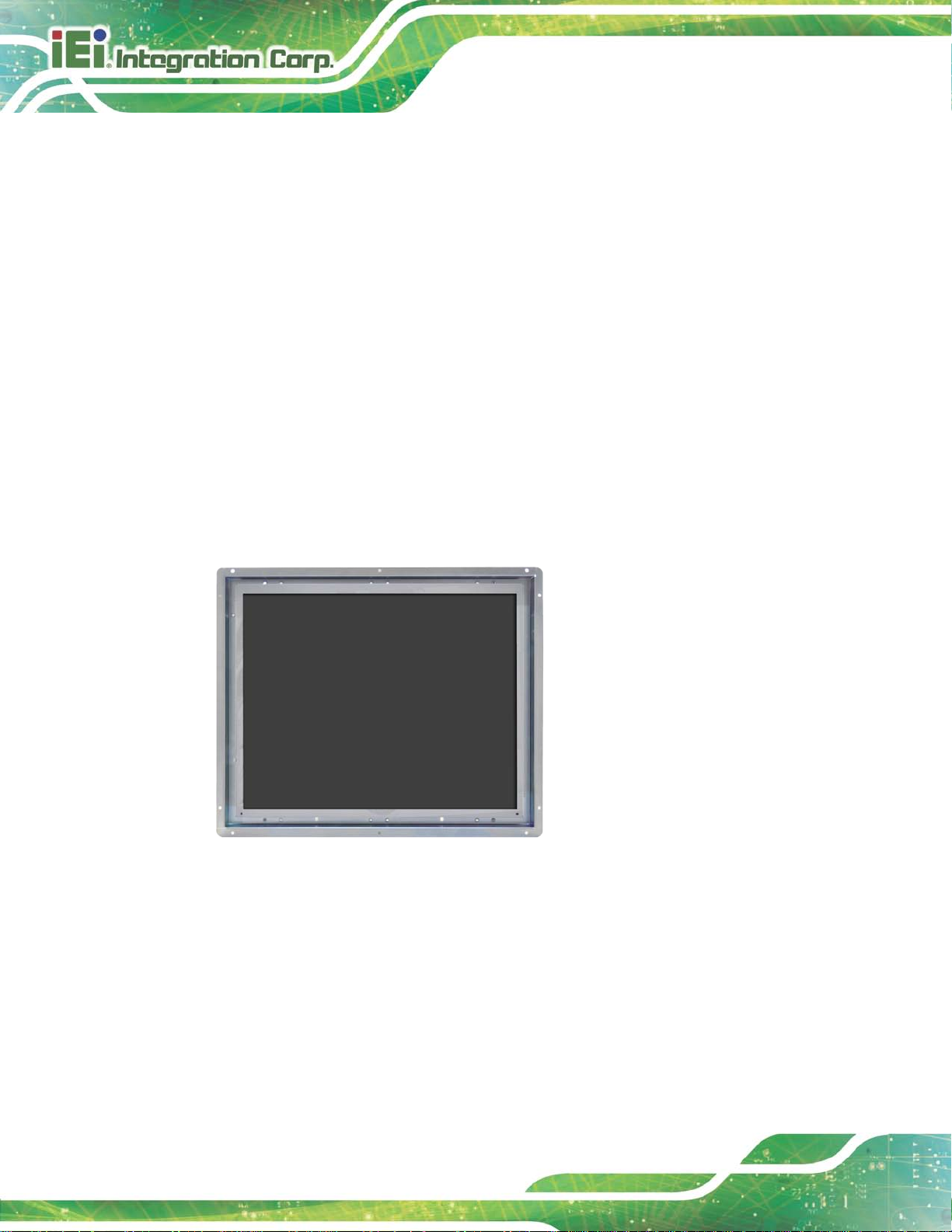
Figure 1 1: LCD-KIT-F Series
The LCD-KIT-F series LCD monitor is the latest member of IEI’s line of sophisticated
LCD designs, and it has been improved to be RoHS compliant. It is designed to fit
industrial automation, or any other applications that require minimum installation space
and flexible configuration. Flexible analog or digital interfaces are provided for ease of
connection with a management computer. If remote/non-attentive control is preferred,
RS-232 or USB interfaces can be used with customized adapter cables.
1.2 Features
The LCD-KIT-F series have the following standard features:
12.1"~19"open frame architecture for embedded integration
Over 350cd/m² high brightness and 50000hrs MTFB long lifetime panel
Analog VGA or digital DVI interfaces support most of general systems
Various touch panel solution : Resistive / Resistive touch windows / PCAP
Optional 9-36V DC module
multi-touch
-20°C~60°C extended operating temperature
Support software OSD for remote control applications
Page 14

LCD-KIT-F
Page 3
D input, Resistive
D input, Resistive
D input, Resistive
D input, Resistive
D input, Resistive
D input, Resistive
D input, Projected
D input, Projected
D input, Projected
1.3 Mode l Variations
The LCD-KIT-F series offer the following model variations.
Model Number Description
LCD-KIT-F12A-R10 12.1" 600 cd/m² XGA open frame monitor, VGA and DVI-D input, R10
LCD-KIT-F15A-R10 15" 450 cd/m² XGA open frame monitor , VGA and DVI-D input, R 10
LCD-KIT-F17A-R10 17" 350 cd/m² SXGA open frame monitor, VGA and DVI-D input, R10
LCD-KIT-F19A-R10 19" 350 cd/m² SXGA open frame monitor, VGA and DVI-D input, R10
LCD-KIT-F12A/R-R10
LCD-KIT-F15A/R-R10
LCD-KIT-F17A/R-R10
LCD-KIT-F19A/R-R10
LCD-KIT-F12A/TW-R10
LCD-KIT-F15A/TW-R10
LCD-KIT-F17A/TW-R10
LCD-KIT-F19A/TW-R10
12.1" 600 cd/m² XGA open frame monitor, V GA and DVItouch screen RS-232/USB interface,R10
15" 450 cd/m² XGA open frame monitor, VGA and DVI-D input, Resistive
touch screen RS-232/USB interface,R10
17" 350 cd/m² SXGA open frame monitor, VGA and DVItouch screen RS-232/USB interface,R10
19" 350 cd/m² SXGA open frame monitor, VGA and DVItouch screen RS-232/USB interface,R10
12.1" 600 cd/m² XGA open frame monitor, VGA and DVItouch window RS-232/USB interface,R10
15" 450 cd/m² XGA open frame monitor, VGA and DVI-D input, Resistive
touch window RS-232/USB interface,R10
17" 350 cd/m² SXGA open frame monitor, VGA and DVItouch window RS-232/USB interface,R10
19" 350 cd/m² SXGA open frame monitor, VGA and DVItouch window RS-232/USB interface,R10
LCD-KIT-F12A/PC-R10
LCD-KIT-F15A/PC-R10
LCD-KIT-F17A/PC-R10
LCD-KIT-F19A/PC-R10
12.1" 600 cd/m² XGA open frame monitor, VGA and DVIcapacitive touch window USB interfac e ,R10
15" 450 cd/m² XGA open frame monitor, VGA and DVI-D input, Projected
capacitive touch window USB interfac e ,R10
17" 350 cd/m² SXGA open frame monitor, VGA and DVIcapacitive touch window USB interfac e ,R10
19" 350 cd/m² SXGA open frame monitor, VGA and DVIcapacitive touch window USB interfac e ,R10
Table 1-1: LCD-KIT-F Series Model Variations
Page 15
LCD-KIT-F
Page 4
1.4 Applications
IEI’s series of LCD monitors are designed for system manufacturers, integrators, or
value-added res e ller s that want t o provide all the performance, quality and reliability of an
LCD display solution at a c ost effective price. I EI’s LCD kits off er additional components
such as cables, an in verter and power supp ly with control ler interfaces that include VGA
and DVI.
1.5 Extern al Overvie w
The following sections describe the physical lay out of the LCD-KIT-F series LCD monitors.
1.5.1 Front View
The front of the LCD-KIT-F series LCD monitor is a flat panel TFT LCD screen attached to
a metal chassis.
Figure 1-2: Typical LCD-KIT-F Front View
362HFigure 1-2 shows a typical LCD-KIT-F front view.
1.5.2 Rear View
The rear of the LCD-KIT-F series LCD monitor is a metal chassis. An on s creen display
(OSD) contro l button panel , if present, is l ocated verti cally on the lef t side of the chas sis
with the following control buttons:
LCD On/Off
Page 16

LCD-KIT-F
Page 5
Auto
Left
Right
Menu
The OSD panel also has one power LED.
363HFigure 1-3 shows a typical LCD-KIT-F rear panel.
Figure 1-3: Typical LCD-KIT-F Rear View
1.5.3 Connectors
Each LCD-KIT series LCD m onitor has a number of interface connectors on the I/O panel
of the chassis (when viewing the rear panel).
connector panel. Each model may include or exclude additional connectors. Refer to
Section
described in Section
365H2.3 for listings of LCD-KIT-Fs and their connectors. All connectors are fully
366H5.4.
364HFigure 1-4 shows a typical LCD-KIT-F
Page 17

LCD-KIT-F
Page 6
Figure 1-4: Typical LCD-KIT Connectors
1.6 Series Specifications
The table below shows the LCD-KIT-F Series specifications.
Model LCD-KIT-F12A LCD-KIT-F15A LCD-KIT-F17A LCD-KIT-F19A
LCD Size 12.1" 15” 17” 19"
Resolution 1024 x 768 1024 x 768 1280 x 1024 1280 x 1024
Brightness (cd/m2) 600 450 350 350
Contrast Ratio 700:1 800:1 800:1 1000:1
Display Color 16.2M 16.2M 16.7M 16.7M
Pixel Pitch (mm) 0.24 0.297 0.264 0.294
Viewing Angle (H/V) 160°/140° 160°/150° 170°/160° 170°/160°
AD Board AV-60381
Input Interface Analog VGA, DVI-D, RS-232/USB(Optional for Touch)
Touchscreen &
controller
OSD function 5 Key OSD
Smart-OSD Yes
Dimensions
(W x H x D mm)
Resistive type 5-wire single touch / Penm o unt 600 0 or Pro jected cap ac itive 2-point touch /
EETI EXC7200 (Assembly by adhesive tape)
323.8 x 263.8 x 40.3 380.1 x 304.6 x 43.2 410 x 343 x 49. 4 449 x 374 x 49.45
Page 18

LCD-KIT-F
Page 7
Model LCD-KIT-F12A LCD-KIT-F15A LCD-KIT-F17A LCD-KIT-F19A
Operating Temperature -20°C~60°C
Storage
Temperature
Humidity 10% to 95% (non-condensing)
Input Voltage 12VDC, 9~36V(Optional, with LCD-KIT-F-936160-R10)
Construction Material sheet metal rear cover SPCC
Mounting Panel Mount, Rear Mount, VESA 100
-20°C~70°C
1.7 Certifications
All LCD-KIT-F series LCD monitor models comply with the following international
standards:
RoHS
For a more detailed description of these standards, please refer to Appendix D.
Page 19

LCD-KIT-F
Page 8
Chapter
2
2 Mechanical Overview
Page 20

LCD-KIT-F
Page 9
2.1 Introduction
This chapter describes the general mechanical over view of the LCD-KIT-F series LCD
monitors including rear panel variations, available interfaces and overall dimensions.
2.2 Rear Panel
The following models of the LCD-KIT-F series LCD monitor have an OSD cont rol panel
located vertically along the left side of the rear panel:
LCD-KIT-F12A
LCD-KIT-F15A
LCD-KIT-F17A
LCD-KIT-F19A
370HFigure 2-1 shows the location of the rear panel OSD controls.
Figure 2-1: Rear Panel
2.3 Connector Panel
All external peripheral interface connectors are located on the rear panel of the LCD-KIT-F
series LCD monitor. The following sections describe the rear panel variants and their
associated connectors.
Page 21

LCD-KIT-F
Page 10
2.3.1 Available Connectors
There are a number of r ear pan el per ipher al de vice co nnector s a vailab le for th e LC D-KIT
series LCD monitor.
VGA connector
DVI-D connector
12 V DC power connector
9~36 V DC terminal block (Optional)
RS-232 connector (Optional for T ouch)
USB connector (Optional for T ouch)
2.4 Phys ical Dimens ions
The following sections describe the physical dimensions for each model of the LCD-KIT-F
series LCD monitor.
2.4.1 G ener al Phys ical Dimens ions
General physical dim ensions for the LCD-KIT-F series LC D monitors are s hown in 372HTable
2-1.
Model Width (mm) Height (mm) Depth (mm)
LCD-KIT-F12A 323.8 263.8 40.3
LCD-KIT-F15A 380.1 304.6 43.2
LCD-KIT-F17A 410 343 49.4
LCD-KIT-F19A 449 374 49.45
Table 2-1: General Physical Dimensions
Page 22

LCD-KIT-F
Page 11
2.4.2 LCD-KIT-F-12A P hys ical Dimens ions
The physical dimensions of the LCD-KIT-F-12A are shown in 375HFigure 2-5.
Figure 2-2: LCD-KIT-F-12A Physical Dimensions (millimeters)
Page 23

LCD-KIT-F
Page 12
2.4.3 LCD-KIT-F-15A Phys ical Dimens ions
The physical dimensions of the LCD-KIT-F-15A are sho wn in 375HFigure 2-3.
Figure 2-3: LCD-KIT-F-15A Physical Dimensions (millimeters)
Page 24

LCD-KIT-F
Page 13
2.4.4 LCD-KIT-F-17A Phys ical Dimens ions
The physical dimensions of the LCD-KIT-F-17A are shown in 375HFigure 2-4.
Figure 2-4: LCD-KIT-F-17A Physical Dimensions (millimeters)
Page 25

LCD-KIT-F
Page 14
2.4.5 LCD-KIT-F-19A Phys ical Dimens ions
The physical dimensions of the LCD-KIT-F-19A are shown in 375HFigure 2-5.
Figure 2-5: LCD-KIT-F-19A Physical Dimensions (millimeters)
Page 26

LCD-KIT-F
Page 15
2.5 Mounting Holes
Each LCD-KIT-F series LCD monitor has mounting holes located on the rear pan e l . 380HTable
2-2 details the number of mounting holes for each model of the LCD-KIT series LCD
monitor. Refer to Section
Model Number of Mounting Holes
LCD-KIT-F12A 20
LCD-KIT-F15A 20
LCD-KIT-F17A 20
LCD-KIT-F19A 20
Table 2-2: Mounting Holes
381H2.4 for more information.
Page 27

LCD-KIT-F
Page 16
Chapter
3
3 LCD Specificat ions
Page 28
LCD-KIT-F
Page 17
3.1 LCD S pecifications
Detailed specifications for the LCD screens are listed in the following sections.
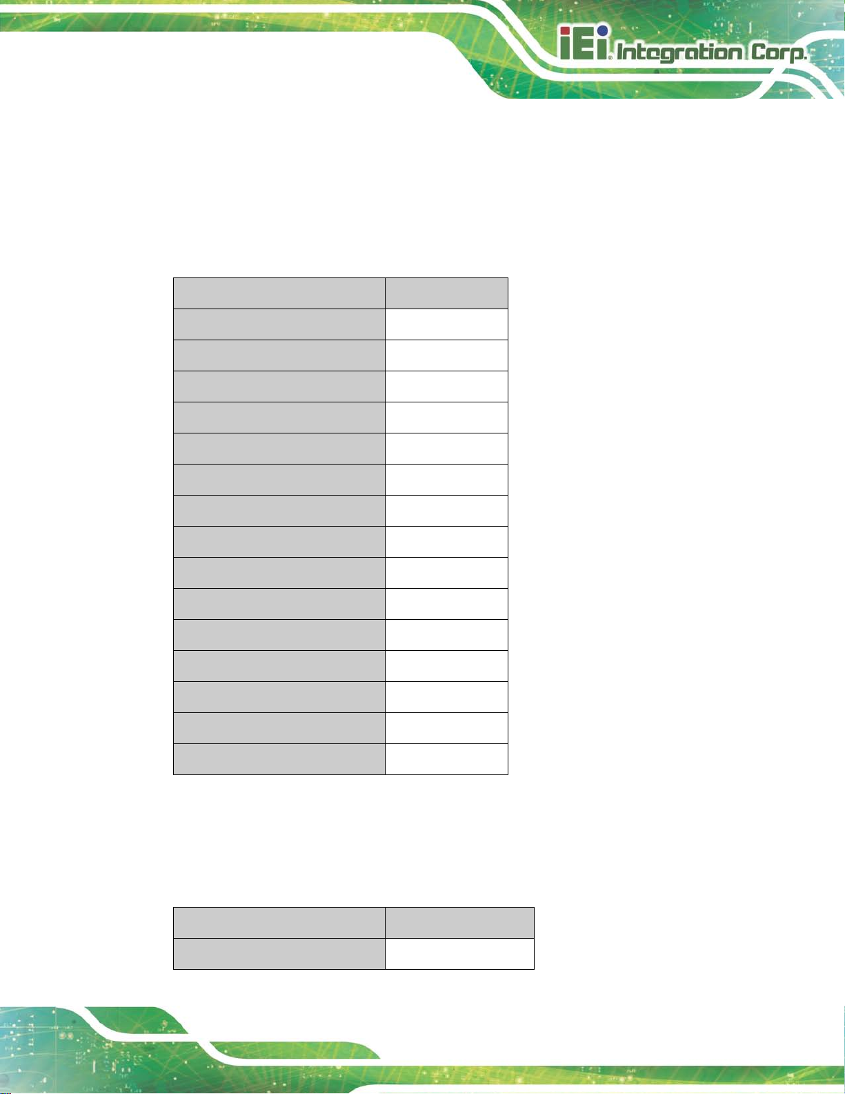
3.1.1 LCD-KIT-F12A LCD Specifications
The table below lists the LCD-KIT-F12A LCD specifications.
Item s LCD-KIT-F12A
Size
Backlight
Brightness (cd/m2)
Resolution
Screen Scale
Life Time
Contrast Ratio
View Angle (H/V)
Inte rface
Operating Temperature
Active Area (mm)
Pixel Pitc h (mm)
Mode
12.1
LED
600
1024 x 768
4:3
50000H
700:1
160/140
1ch LVDS
-30°C ~80°C
245.75 x 184.32
0.24
Normal White
Number of Colors
Supply Voltage (V)
Table 3-1: LCD-KIT-F12A LCD Specifications
16.2M
3.3
3.1.2 LCD-KIT-F15A LCD Specifications
The table below lists the LCD-KIT-F15A LCD specifications.
Item s LCD-KIT-F15A
Size
15”
Page 29
LCD-KIT-F
Page 18
Backlight
Brightness (cd/m2)
Resolution
Screen Scale
Life Time
Contrast Ratio
View Angle (H/V)
Interface
Operating Temperature
Active Area (mm)
Pixel Pitc h (mm)
Display Mode
Display Color
LED
450
1024 x 768
4:3
70000H
800:1
160/150
1ch LVDS
-30°C ~85°C
304.128 x 228.096
0.297
Normal White
16.2M
Supply Voltage (V)
Table 3-2: LCD-KIT-F15A LCD Specifications
3.3
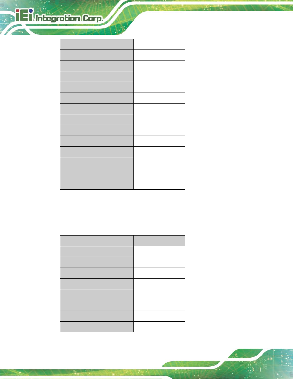
3.1.3 LCD-KIT-F17A LCD Specifications
The table below lists the LCD-KIT-F17A LCD specifications.
Item s LCD-KIT-F17A
Size
Backlight
Brightness (cd/m2)
Resolution
Screen Scale
Life Time
Contrast Ratio
17”
LED
350
1280 x 1024
4:3
50000H
800:1
View Angle (H/V)
170/160
Page 30

LCD-KIT-F
Page 19
Interface
Operating Temperature
Active Area (mm)
Pixel Pitc h (mm)
Display Mode
Display Color
Supply Voltage (V)
Table 3-3: LCD-KIT-F17A LCD Specifications
2ch LVDS
-30°C ~70°C
337.920 x 270.336
0.264
Normal White
16.7M
5
3.1.4 LCD-KIT-F19A LCD Specifications
The table below lists the LCD-KIT-F19A LCD specifications.
Item s LCD-KIT-F19A
Size
19”
Backlight
Brightness (cd/m2)
Resolution
Screen Scale
Life Time
Contrast Ratio
View Angle (H/V)
Active Area (mm)
Pixel Pitc h (mm)
Display Mode
Display Color
Supply Voltage (V)
Table 3-4: LCD-KIT-F19A LCD Specifications
LED
350
1280 x 1024
4:3
50000H
1000:1
170/160
304.1 x 228.1
0.294
Normal White
16.7M
3.3
Page 31
LCD-KIT-F
Page 20
3.2 Power Adapte rs
382HTable 3-6 lists the power adapter specifications.
Model FSP036-RBBN2
Input Voltage Range 90-264VAC
Input Frequency 47-63Hz
Output Voltage 12 V
Output Voltage 3 A
Output Watts 36W
Efficiency 86%
Operating Temperature 0°C~40°C
Storage Temperature -20°C~70°C
Table 3-5: Power Adapter Specifications
3.3 9~36V DC Module
382HTable 3-6 lists the 9~36V DC module specifications.
Model LCD-KIT-F-936160-R10
Input Voltage Range 9 V~36 V
Output Voltage 12 V
Output Watts 60W
Table 3-6: 9~36V DC Module Specifications
Page 32

LCD-KIT-F
Page 21
Chapter
4
4 AD Board
Page 33

LCD-KIT-F
Page 22
4.1 AD Board Overview
The LCD-KIT-F series LCD monitor AD board provides a wide variety of control interfaces.
The following sections describe each AD board in detail.
4.2 AV-60381 AD Board
The connec tor locations of the AV-60381 ar e sho wn in Figure 4-1. The Pin 1 loca tions of
the on-board connectors are also indic ated in the dia gram s belo w. The connec tor pinouts
for these connectors are listed in the following sections.
Figure 4-1: AV-60381 AD Board Layout Diagram
4.2.1 AV-60381 Peripheral Interface Connectors
527HTable 4-1 shows a list of the peripheral int erface connec tors on the AV-60381 A D board.
Pinouts of the connectors that are used i n the LCD-KIT-F can be found in the f ollowing
sections.
Connector Type Label
Auto dimming connector 6-pin wafer, p=1.25 mm CN4
Backlight Inverter connector 6-pin wafer, p=2.00 mm INVERTER1
Page 34

LCD-KIT-F
Page 23
COM debug port connector 2-pin wafer, p=2.00 mm CN2
LVDS connector 30-pin crimp, p=1.25 mm LVDS1
OSD keypad connector 12-pin wafer, p=1.00 mm KEYPAD1
Power input connector 3-pin wafer, p=3.96 mm PWR2
Power input connector (+12 V) 2-pin wafer, p=2.00 mm CN15
Power output connector 2-pin wafer, p=2.00 mm CN16
RS-232 connector for touchscreen 6-pin wafer, p=1.25 mm RS232_1
SPI flash connector 6-pin wafer, p=1.25 mm JSPI1
USB connector for touchscreen 4-pin wafer, p=1.25 mm USB_TOUCH1
Touchscreen connector 9-pin wafer, p=1.25 mm J1
10-pin box header, p=2.00
VGA connector
mm
Jumper Type Label
Backlight voltage select jumper 6-pin header, p=2.54 mm JP5
LVDS panel voltage select jumper 6-pin header, p=2.54 mm JP2
Power input setting jumper 6-pin header, p=2.54 mm JP4
Touchscreen type select jumper 2-pin header, p=2.00 mm JP1
Table 4-1: AV-60381 Peripheral Interface Connectors
4.2.2 Backlight Inverter Connector (INVERTER1)
PIN NO. DESCRIPTION
1 BKL_POWER1
2 BKL_POWER1
VGA2
3 ENABKL
4 BRIGHTNESS
5 GND
Page 35

LCD-KIT-F
Page 24
6 GND
Table 4-2: Backlight Inverter Connector (INVERTER1) Pinouts
4.2.3 LVDS Connector (LVDS1)
PIN NO. DESCRIPTION PIN NO. DESCRIPTION
1 GND 2 GND
3 A0P_C 4 A0M_C
5 A1P_C 6 A1M_C
7 A2P_C 8 A2M_C
9 CLK1P_C 10 CLK1M_C
11 A3P_C 12 A3M_C
13 GND 14 GND
15 A4P_C 16 A4M_C
17 A5P_C 18 A5M_C
19 A6P_C 20 A6M_C
21 CLK2P_C 22 CLK2M_C
23 A7P_C 24 A7M_C
25 GND 26 GND
27 VCC 28 VCC
29 VCC 30 VCC
Table 4-3: LVDS Connector (LVDS1) Pinouts
4.2.4 OSD Key pad Connector (KEYPAD1)
PIN NO. DESCRIPTION PIN NO. DESCRIPTION
1 +5V_OSD(NC) 2 +12V(NC)
3 Left 4 Auto
5 Right 6 Power
7 Menu 8 Led_GREED (UP)
9 Down (NC) 10 Led_RED
11 GND 12 +3.3V_DVDD(NC)
Table 4-4: OSD Keypad Connector (KEYPAD1) Pinouts
Page 36

LCD-KIT-F
Page 25
4.2.5 Power Input Connector (PWR2)
PIN NO. DESCRIPTION
1 +9 V ~ +36 V to external power module
2 GND
3 +12 V input
Table 4-5: Power Input Connector (PWR2) Pinouts
4.2.6 RS-232 Connector for Touchscreen (RS232_1)
PIN NO. DESCRIPTION
1 NDSR
2 NRX
3 NRTS
4 NTX
5 NDTR
6 GND
Table 4-6: RS-232 Connector for Touchscreen (RS232_1) Pinouts
4.2.7 USB Connector for Touchscreen (USB_TOUCH1)
PIN NO. DESCRIPTION
1 VCC_TOUCH
2 D2F3 D2F+
4 GND
Table 4-7: USB Connector for Touchscreen (USB_TOUCH1) Pinouts
4.2.8 Touchscreen Connector (J1)
PIN NO. DESCRIPTION PIN NO. DESCRIPTION
1 X+ 2 X-
3 Y+ 4 SENSE
5 X+ 6 X-
Page 37

LCD-KIT-F
Page 26
PIN NO. DESCRIPTION PIN NO. DESCRIPTION
7 Y+ 8 Y+
9 GND
Table 4-8: Touchscreen Connector (J1) Pinouts
4.2.9 VGA Connector (VGA2)
PIN NO. DESCRIPTION PIN NO. DESCRIPTION
1 RED 2 SMCLK
3 GREEN 4 SMDATA
5 BLUE 6 GND
7 H-SYNC 8 GND
9 V-SYNC 10 GND
Table 4-9: VGA Connector (VGA2) Pinouts
4.2.10 Backlight Voltage Select Jumper (JP5)
DESCRIPTION
Short 1-2 +3.3 V
Short 3-4 +5 V
Short 5-6 +12 V
Table 4-10: Backlight Voltage Select Jumper (JP5) Pinouts
4.2.11 LVDS Panel Voltage Select Jumper (JP2)
DESCRIPTION
Short 1-2 +3.3 V (for 6 .5” and 8”)
Short 3-4 +5 V
Short 5-6 NC
Table 4-11: LVDS Panel Volt age Select Jump er (JP2) Pinouts
Page 38

LCD-KIT-F
Page 27
4.2.12 Power Input Setting J umper (JP4)
DESCRIPTION
Short 1-3, 2-4 +12 V from power jack (PRW1)
Short 3-5, 4-6
Input with external connector
(external power module is needed)
Table 4-12: Power Input Setting Jumper (JP4) Pinouts
4.2.13 Touchs creen Type Select Jumper (JP1)
DESCRIPTION
1 5-wire touchscreen
2 4-wire/8-wire touchscreen
Table 4-13: Touchscreen Type Select Jumper (JP1) Pinouts
Page 39

LCD-KIT-F
Page 28
Chapter
5
5 Installation
Page 40

LCD-KIT-F
Page 29
5.1 Installation Precautions
When installing the LCD-KIT-F series LCD monitor, please follow the precautio ns listed
below:
Read the user manual: The user manual provides a complete description of
the LCD-KIT-F series LCD monitor, installation instructions and configuration
options.
DANGER! Disconnect Power: Power to the LCD monitor must be
disconnected when installing the LCD-KIT-F series LCD monitor, or before
any attempt is made to access the rear panel. Electric shock and personal
injury might occur if the rear panel of the monitor is opened while the power
cord is still connected to an electrical outlet.
Qualified Personnel: The LCD-KIT-F series LCD monitor must be installed
and operated only by trained and qualified personnel. Maintenance, upgrades,
or repairs may only be carried out by qualified personnel who are familiar with
the associated dangers.
Mounting: Since the monitor may weigh up to 10 kg (not including a swing
arm or other accessories), please ensure at least two people assist with
mounting the monitor.
Air Circulation: Make sure there is sufficient air circulation when installing the
monitor. The monitor’s cooling vents must not be obstructed by any objects.
Blocking the vents can cause overheating of the monitor. Leave at least 5 cm
of clearance around the monitor to prevent overheating.
Grounding: The monitor should be properly grounded. The voltage feeds
must not be overloaded. Adjust the cabling and provide external overcharge
protection per the electrical values indicated on the label attached to the back
of the monitor.
Anti-static Discharge: The rear panel of the monitor must to be removed to
configure the monitor’s AD board voltage select jumper. When doing so, be
sure the monitor is disconnected from its power source and take all necessary
safety precautions to avoid electrocution and static discharge to the AD board.
The use of a grounded wrist strap and an anti-static work pad is
recommended.
Page 41

LCD-KIT-F
Page 30
5.2 Unpacking
5.2.1 Packaging
When shipped, the LCD-KIT-F series LCD monitor is wrapped in a plastic bag. Two
polystyrene ends are placed on either side of t he monitor. The monitor is then placed into
a first (internal) cardboard box. This box is then sealed and placed into a second (external)
cardboard box. The second box is also sealed. A bag containing accessory items is
placed with the monitor in the internal (first) box.
5.2.2 Unpacking Procedure
To unpack the LCD-KIT-F series LCD monitor, follow the steps below:
WARNING:
The front side LCD screen has a protective plastic cover stuck to the
screen. Only remove the pl astic cover af ter the LCD-KIT-F series LCD
monitor has been properly installed. This ensures the screen is
protected during the installation process.
Step 1: Use box cutters, a knife or a sharp pair of scissors that seals the top side of the
external (second) box.
Step 2: Open the external (second) box.
Step 3: Use box cutters, a knife or a sharp pair of scissors that seals the top side of the
internal (first) box.
Step 4: Lift the monitor out of the boxes.
Step 5: Remove both polystyrene ends, one from each side.
Step 6: Pull the plastic cover off the LCD-KIT-F series LCD monitor.
Step 7: Make sure all the components listed in the packing list are present. S tep 0:
Page 42

LCD-KIT-F
Page 31
5.2.3 Packing List
All the monitors in the LCD-KIT-F series are shipped with the following components:
Quantity Ite m Ima g e
Standard
1 LCD-KIT series LCD monitor
1 AC power adapter
(P/N: 63040-010036-121-RS)
1 AC power cable
1 USB cable (for Touch)
(P/N: 32001-006100-200-RS)
1 VGA cable
(P/N: 32000-036200-RS)
1 Utility CD
Optional
RS-232 cable (for Touch)
(P/N: 32005-001100-200-RS)
DVI cable
(P/N: 32000-086600-RS)
Panel mount kit
(P/N: FPK-01-R10)
(P/N: FPK-02-R10)
Page 43
LCD-KIT-F
Page 32
If any of these items are missing or damaged, contact the distributor or sales
representative imm ediately.
5.3 Pre-in s tallat ion Pr eparation
5.3.1 Tools
Before installing the LCD-KIT-F series LCD m onitor, m ake s ure the f ollow ing t ools ar e on
hand:
Philips (crosshead) screwdri ver: All the retention screws on the system are
Philips screws.
Soft working mat: When the LCD-KIT-F series LCD monitor is installed, the
screen is placed on the working surface. It is therefore important to rest the
MPC industrial workstation on a soft mat that cannot damage the LCD screen
on the front of the LCD-KIT-F series LCD monitor.
5.4 Connectors
390HTable 5-1 lists the rear panel connectors for the LCD-KIT-F series LCD monitors.
LCD-KIT DVI-D VGA
LCD-KIT-F12A-R10
LCD-KIT-F15A-R10
LCD-KIT-F17A-R10
LCD-KIT-F19A-R10
LCD-KIT-F12A/R-R10
LCD-KIT-F15A/R-R10
LCD-KIT-F17A/R-R10
LCD-KIT-F19A/R-R10
LCD-KIT-F12A/TW-R10
12V DC
9~36V Terminal
USB RS-232
Jack
Yes Yes Yes Optional No No
Yes Yes Yes
Yes Yes Yes Optional No No
Yes Yes Yes
Yes Yes Yes Optional Yes Yes
Yes Yes Yes
Yes Yes Yes Optional Yes Yes
Yes Yes Yes
Yes Yes Yes Optional Yes Yes
Block
Optional
Optional
Optional
Optional
No No
No No
Yes Yes
Yes Yes
LCD-KIT-F15A/TW-R10
LCD-KIT-F17A/TW-R10
Yes Yes Yes
Yes Yes Yes Optional Yes Yes
Optional
Yes Yes
Page 44

LCD-KIT-F
Page 33
NC
LCD-KIT DVI-D VGA
LCD-KIT-F19A/TW-R10
LCD-KIT-F12A/PC-R10
LCD-KIT-F15A/PC-R10
LCD-KIT-F17A/PC-R10
LCD-KIT-F19A/PC-R10
12V DC
Jack
Yes Yes Yes Optional Yes Yes
Yes Yes Yes
Yes Yes Yes Optional Yes No
Yes Yes Yes
Yes Yes Yes Optional Yes No
9~36V Terminal
Block
Optional
Optional
USB RS-232
Yes No
Yes No
Table 5-1: Rear Panel Connectors
5.4.1 VGA Connector
Use the rear panel standar d 15-pin female VGA conn ector to connect the LCD monitor to
the system graphics interface.
Pin Description Pin Description Pin Description
1 RED 6 GROUND 11 NC
2 GREEN 7 GROUND 12 DDCDAT
3 BLUE 8 GROUND 13 HSYNC
4 NC 9 NC 14 VSYNC
5 GROUND 10 GROUND 15 DDCCLK
Table 5-2: VGA Connector Pinouts
Figure 5-1: VGA Connector
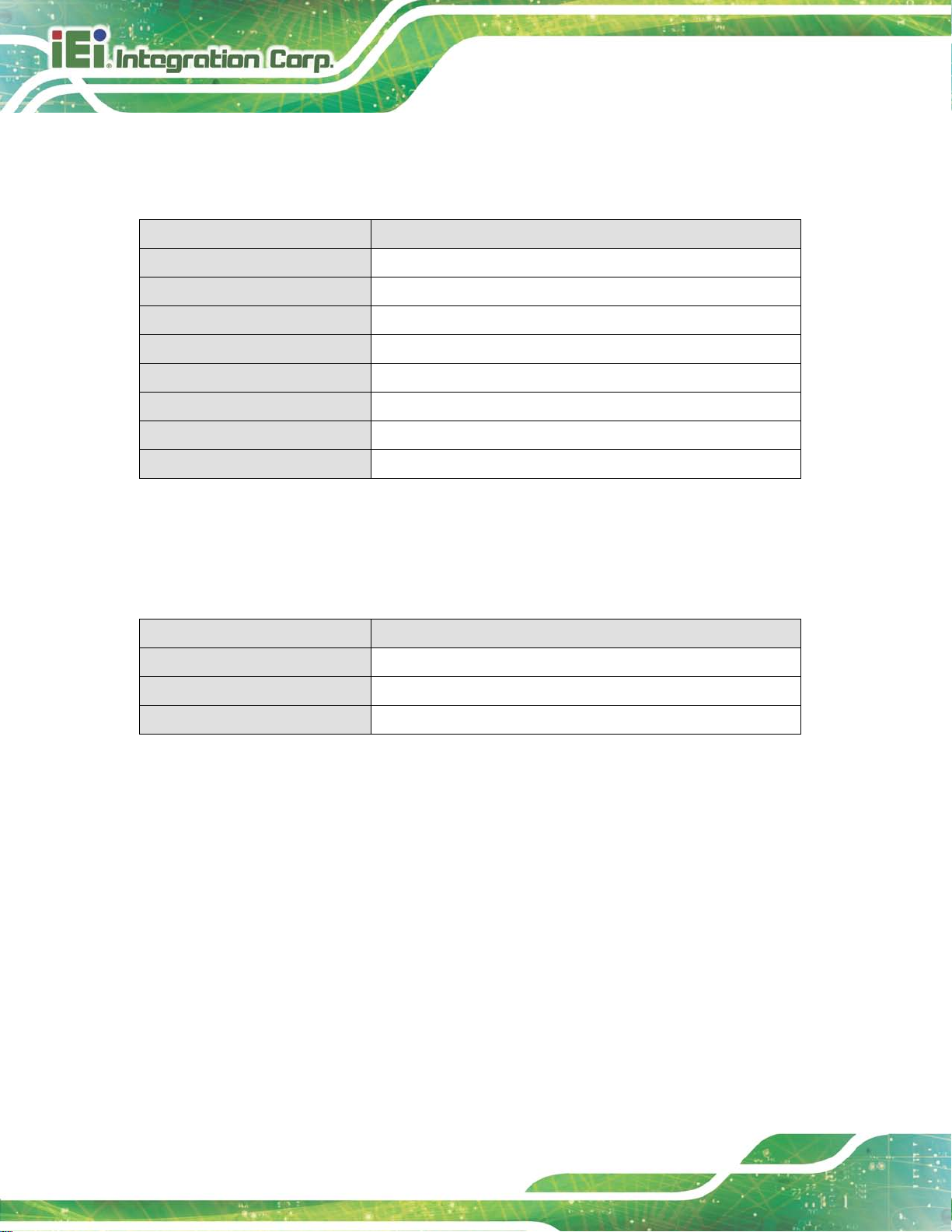
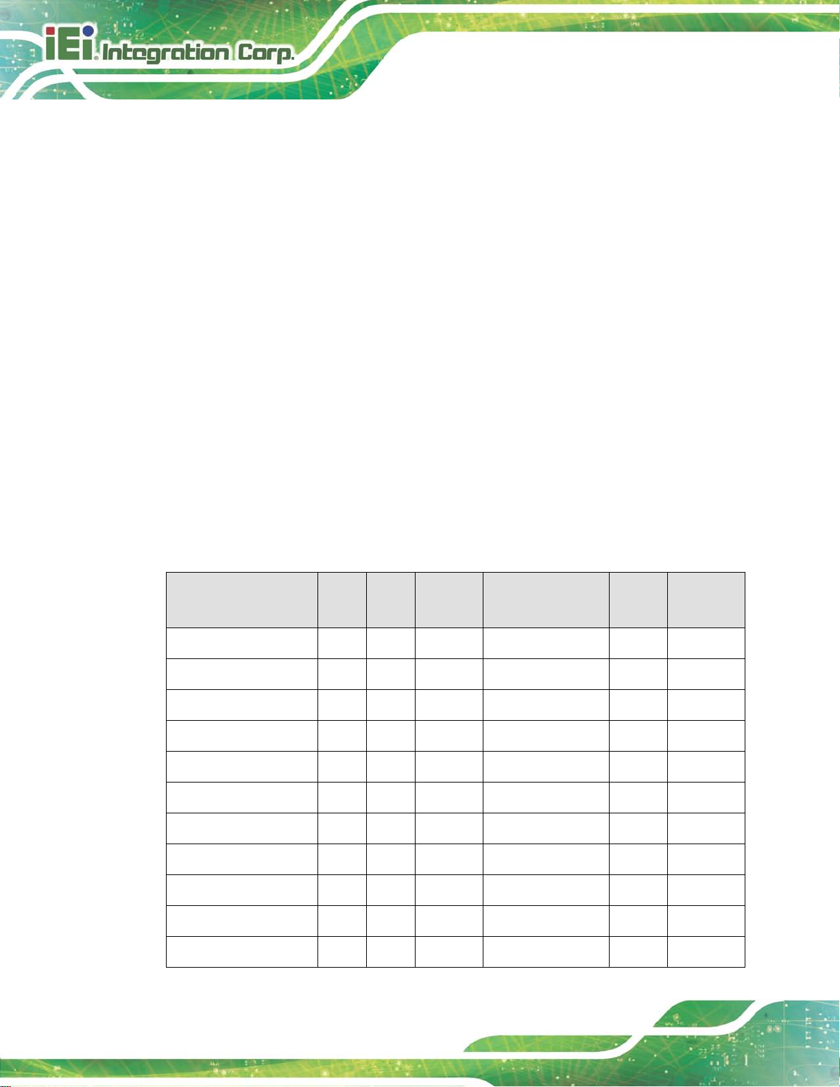
5.4.2 DVI-D Connector
The 24-pin Digital Visual Interface (DVI) connector connects to high-speed,
high-resolution digital displays. The DVI-D connector s upports only digital signals.
PIN DESCRIPTION PIN DESCRIPTION
1
TMDS Data2-
13
Page 45
LCD-KIT-F
Page 34
4
8
NC
NC
2
3
5
6
7
9
10
11
12
Table 5-3: DVI-D Connector Pinouts
TMDS Data2+
GND
N/C
N/C
DDC Clock [SCL]
DDC Data [SDA]
Analog vertical sync
TMDS Data1TMDS Data1+
GND
14
15
16
17
18
19
20
21
22
23
24
PVDD1
GND
GND
TMDS Data0TMDS Data0+
GND
NC
GND
TMDS Clock +
TMDS Clock -
Figure 5-2: DVI-D Connector
5.4.3 12V Power Connector
Use the rear panel +12V DC jack to connect the monitor to a power source.
Figure 5-3: 12V Power Connector
5.4.4 9 V~36 V Terminal Block (Optional)
Connect the leads of 9 V ~ 36 V DC power supply into the terminal block . Mak e s ure that
the power and ground wires are attached to the correct sockets of the connector.
Page 46

LCD-KIT-F
Page 35
Figure 5-4: 3-pin Terminal Block
5.4.5 RS-232 for Touch Panel Connector
Use the rear panel standard RS-232 DB-9 female touch panel connector to connec t the
monitor to the system graphics interface.
PIN DESCRIPTION PIN DESCRIPTION
1 N/A 6 NDSR
2 NRX 7 NRTS
3 NTX 8 N/A
4 NDTR 9 N/A
5 GND
Table 5-4: RS-232 Touch Panel Connector Pinouts
Figure 5-5: RS-232 Touch Panel Connector
Page 47

LCD-KIT-F
Page 36
5.4.6 USB for Touch Panel Connector
Use the rear panel standard USB touch panel conn ector to connect the monitor to the
system graphics interface.
PIN DESCRIPTION PIN DESCRIPTION
1 VCC 5 VCC
2 Data- 6 Data3 Data+ 7 Data+
4 GND 8 GND
Table 5-5: USB Touch Panel Connector Pinouts
Figure 5-6: USB Touch Panel Connector
5.5 Mounting the LCD-KIT-F Series LCD Monitor
5.5.1 Panel Mounting
Each model of the LCD-KIT-F series LCD monitor has a s eries of mounting sl ots located
on the top, side and bottom panels for mounting the monitor to a panel.
540HTable 2-2 lists t he number of mounting clam ps and ho lders re quired to mount the monitor
to a panel.
Model Mounting Clamps Clamp Holders
LCD-KIT-F12A 10 10
LCD-KIT-F15A 10 10
LCD-KIT-F17A 10 10
LCD-KIT-F19A 10 10
Table 3-6: Panel Mounting Clamps
Page 48

LCD-KIT-F
Page 37
Figure 5-7: Mounting Clamps Holder
Figure 5-8: Mounting Clamps
To mount the LCD-KIT-F series LCD monitor into a panel, please follow the steps below.
Step 1: Select the position on the panel to mount the monitor.
Step 2: Cut out a section of the panel that corresponds to the rear panel dimensions of
the monitor. Take care that the panel section that is cut out is smaller than the
overall size of the metal frame that surrounds the monitor but just large enough
for the rear panel of the monitor to fit through.
Step 3: Secure the mounting clamps holders to the corresponding holes on the rear of
the monitor.
Page 49

LCD-KIT-F
Page 38
Figure 5-9: Secure the Mounting Clamps Holders
Step 4: Slide the monitor through the hole until the aluminum frame is flush against the
panel.
Step 5: Insert the panel mounting clamps into the pre-formed holes of the clamp
holders.
Figure 5-10: Panel Mounting Clamp Position
Step 6: Tighten the screws that pass through the panel mounting clamps until the plastic
caps at the front of all the screws are firmly secured to the panel.
Page 50

LCD-KIT-F
Page 39
Figure 5-11: Mounting Clamps Holder Dimensions
Figure 5-12: Ultra Set Plate Dimensions
Figure 5-13: Bolt Dimensions
Page 51

LCD-KIT-F
Page 40
Figure 5-14: Steering Button Dimensions
Page 52

LCD-KIT-F
Page 41
Chapter
6
6 On-Screen-Display (OSD)
Controls
Page 53

LCD-KIT-F
Page 42
6.1 OSD Keypad
There are several on-screen-display (OSD) control buttons of the OSD keypad on the
monitor rear panel. Figure 6-1 shows the 5-key membrane OSD keypad of the LCD
monitors.
Figure 6-1: OSD Keypad
The function of each button is described in the following table.
LCD ON/OFF Press this button to turn on or turn off the LCD screen.
AUTO
LEFT
RIGHT
MENU
Table 6-1: OSD Control Buttons
Press this button to automatically adjust the screen. When inside a menu, press
this button to confirm the selection of the item.
Press this button to decrease the value, or to scroll up from one selected item to
another.
Press this button to increase the value, or to scroll down from one selected item
to another.
Press this button to open the OSD window , ex it the mai n menu or the current
menu.
Page 54

LCD-KIT-F
Page 43
6.2 OSD Menu Structure
572HTable 6-2 shows the OSD menu structure for all models of the DM-F series LCD monitor.
Level 0 Level 1 Level 2 Value
Image Brightness 0 to 100
Contrast 0 to 100
Sharpness -4 to 4
Color Auto
Color temp 5000K
6500K
9300K
User
Reset
Display Auto Adjust
Phase 0 to 100
Clock 0 to 100
Display Position
Display Modes Gamma off
System Input Display Port
VGA
DVI/HDMI
autoscan
OSD Setting Timer 10sec/30sec/60sec
Rotation
Position
Transparency 0 to 100
Information
Reset
Gamma 2.2
0°/90°/180°/270°
Table 6-2: OSD Menu Structure
Page 55

LCD-KIT-F
Page 44
tness of screen. T his function
etting this valu e too high or to o low
djusting this value too
sharpness level. This option softens the edges around
6.3 Using the OSD
OSD menu options are described below.
6.3.1 Image Menu
Image menu features are shown in Figure 6-2.
Figure 6-2: Image Menu
The brightness opt ion adjusts the brigh
Brightness
Contrast
Sharpness
Color
adjusts the offset value of ADC. S
will affect the quality of image.
This function adjusts the g ain value of ADC. A
high or too low will worsen the quality of image.
Adjusts the
objects on the screen.
Provides options for color settings. (Figure 6-3)
Page 56

LCD-KIT-F
Page 45
6.3.1.1 Color Setting
Color settings are shown in Figure 6-3.
Figure 6-3: Color Settings
auto
Color temp
Automatically adjusts the color settings.
This item allows adjustment of the following items.
5000k – NTSC standard Kelvin
6500k – NTSC standard Kelvin
9300k – NTSC standard Kelvin
User – This item allows fine-tuning the balance am ong Red,
Green, and Blue color hues if images look garish or unrealistic.
Page 57
LCD-KIT-F
Page 46
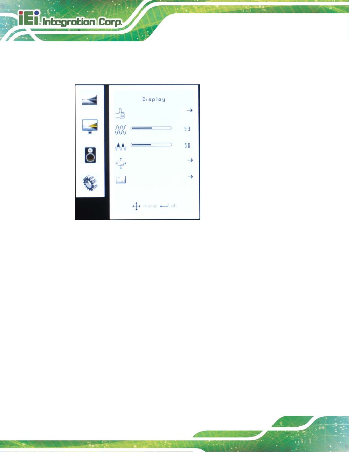
6.3.2 Dis play Men u
Display menu features ar e s ho wn in Figure 6-4.
Figure 6-4: Display Menu
Auto Adjust
Phase
Clock
Display Position
Display Mode
Automatically adjusts the LCD screen position.
Adjusts the input signal (analog only)
Adjusts the dot clock position
Adjusts the horizontal and vertical position of the display screen
This item allows adjustment of the Gamma.
Page 58

LCD-KIT-F
Page 47
version,
6.3.3 System Me n u
System menu featur es are s ho wn in Figure 6-5.
Figure 6-5: System Menu
Input
OSD Settings
Information
Reset
Allows selection of input device to use. (Figure 6-6)
Provides options for OSD configuration. (Figure 6-7)
Provides inform ation on the LCD monitor, such as firmware
release date and input resolution.
Restores the default OSD settings. Note that this will restore all default
display settings.
Page 59

LCD-KIT-F
Page 48
6.3.3.1 Input
Input options are shown in Figure 6-6.
Figure 6-6: Input Options
Input options are described below.
Display Port
VGA
HDMI
autoscan
This item sets the input device to display port.
This item sets the input device to VGA.
This item sets the input device to HDMI.
Selects the input device to use automatically.
Page 60

LCD-KIT-F
Page 49
Determines how many seconds the OSD screen stays on screen
6.3.3.2 OSD Settings
The OSD settings are shown in Figure 6-7.
Figure 6-7: OSD Settings Menu
OSD settings are described below.
Timer
Rotation
Position
Transparency
before it disappears when OSD is left unattended.
Adjusts the OSD rotation angle on the screen.
Adjusts the OSD position on the screen.
Adjust the transparency of the OSD menu background.
Page 61

LCD-KIT-F
Page 50
Chapter
7
7 Software Driver
Page 62

LCD-KIT-F
Page 51
7.1 Introduction
The touch panel contro ller enables ana log res istive t ouc h panels f or f our-wire, five-wire &
eight-wire models. The c ontroller directl y communicates with the PC system through the
touch panel communications interface. The controller design is superior in sensitivity,
accuracy, and friendl y operation. The touch pa nel driver emulates the left mouse butt on
and the right mouse bu tton functions.
The touch panel driver supports the following operating systems:
Microsoft
o Microsoft
o Microsoft
o Microsoft
o Microsoft
o Microsoft
o Microsoft
Microsoft
o Microsoft
o Microsoft
o Microsoft
Linux Kernel 2.6
DOS
Driver installation is described below.
®
Windows® versions:
®
Windows® 2000
®
Windows® XP
®
Windows® 2003
®
Windows® 2008
®
Windows® Vista
®
Windows® 7
®
Windows® CE versions:
®
Windows® CE 4.2
®
Windows® CE 5.0
®
Windows® CE 6.0
7.2 RS-232 o r USB Tou ch Screen
Before installing the driver, connect the LCD-KIT-F monitor to the motherboard. The
LCD-KIT-F monitors support touch scr een modality through an RS-2 32 or USB interface
connection. Decide through which interface the touch screen is to be controlled.
RS-232 Interface: If the touch screen interface connection is an RS-232
connection, connect the RS-232 connector on the single board computer to
the DB-9 connector of the LCD-KIT-F monitor.
Page 63

LCD-KIT-F
Page 52
USB Interface: If the touch screen interface connection is a USB connection,
connect the USB connector on the single board computer to the external USB
port connector of the LCD-KIT-F monitor.
7.3 Touch Panel Driver Ins tallation
WARNING:
Before the touch screen driver is installed, m ake sure the system is
connected to the m onitor with a USB cable or an RS-232 null cab le.
Also, make sure the VG A connect or on th e system is connec ted to t he
VGA connector on the bottom of the monitor.
To install the touch panel driver for the LCD-KIT-F, please follow the instructions below:
Step 7: Connect the LCD-KIT-F monitor to the single board computer. See above.
Step 8: Install the driver CD. Install the driver CD into the system to which the
LCD-KIT-F monitor is connected.
Step 9: Select the Touch Screen option in the menu of driver CD. The directory in
Figure 7-1 appears.
Figure 7-1: Setup Icon
Page 64

LCD-KIT-F
Page 53
Step 10: Double click the setup icon in Figure 7-1.
Step 11: The Welcome screen in Figure 7-2 appears.
Figure 7-2: Welcome Screen
Step 12: Click Next to continue.
Step 13: The license agreement in Figure 7-3 appears. Accept the terms of the
agreement by clicking I Agree.
Figure 7-3: License Agreement
Page 65

LCD-KIT-F
Page 54
Step 14: The installation destination screen appears. See Figure 7-4. Click Install.
Figure 7-4: Initiate Install
Step 15: The installation of the program begins. See Figure 7-5.
Figure 7-5: Installation Starts
Step 16: When the installation is complete, the complete screen appears. See Figure 7-6.
To complete the installation process click Finish.
Page 66

LCD-KIT-F
Page 55
Figure 7-6: Finish Installation
7.4 Change the Touch Screen Interface
If the touch screen interface must be changed from an RS-232 interface to a USB
interface or, from a USB interface to an RS-232 i nterface, the following steps m ust be
followed.
Step 17: Uninstall the touch screen driver
Step 18: Remove the interface cable i.e. remove the RS-232 cable or the USB cable
Step 19: Install the new cable i.e. install the USB cable or the RS-232 cable.
Step 20: Reinstall the driver CD as described above. Step 0:
7.5 Calibrating the Touch Screen
To calibrate the touch screen cur sor with the motion of the touch screen pen (o r finger),
please follow the steps below:
Step 1: Make sure the system is properly connected through an RS-232 or a USB
interface to the LCD-KIT-F monitor.
Step 2: Make sure the touch screen driver is properly installed.
Page 67

LCD-KIT-F
Page 56
Step 3: Locate the PenMount Monitor icon in the bottom left corner of the screen.
Figure 7-7: PenMount Monitor Icon
Step 4: Click the icon. A pop up menu appears. See Figure 7-8.
Figure 7-8: PenMount Monitor Popup Menu
Step 5: Click Control Panel in the pop up menu shown in Figure 7-8.
Step 6: The configuration screen in Figure 7-9 appears.
Figure 7-9: Configuration Screen
Page 68

LCD-KIT-F
Page 57
Step 7: Double click the PenMount 6000 icon as shown in Figure 7-9.
Step 8: The calibration initiation screen in Figure 7-10 appears.
Step 9: Select the Standard Calibration button as shown in Figure 7-10.
Figure 7-10: Calibration Initiation Screen
Step 10: The calibration screen in is shown. See Figure 7-11.
Figure 7-11: Calibration Screen
Step 11: Follow the instructions. The user is asked touch the screen at five specified
points after which the screen is calibrated. S t ep 0:
Page 69

LCD-KIT-F
Page 58
396HAppendix
A
A Regulatory Compliance
Page 70

LCD-KIT-F
Page 59
DE CLARATIO N OF CO NF ORMITY
This equipment is in conformity with the following EU directives:
EMC Directive (2004/108/EC, 2014/30/EU)
Low-Voltage Directive (2006/95/EC, 2014/3 5/E U )
RoHS II Directive (2011/65/EU, 2015/863/EU)
Ecodesign Directive 2009/125/EC
If the user modifies and/or install other devices in the equipment, the CE conformity
declaration may no longer apply.
If this equipment has telecommunications functionality, it also complies with the
requirements of the R ad io Equ ipment Directive 2014/53/EU.
English
IEI Integration Corp declares that this equipment is in compliance with the
essential requirements and other relevant provisions of Directive
2014/53/EU.
Български [Bulgarian]
IEI Integration Corp. декларира, че този оборудване е в съответствие със
съществените изисквания и другите приложими правила на Директива
2014/53/EU.
Česky [Czech]
IEI Integration Corp tímto prohlašuje, že tento zařízení je ve shodě se
základními požadavky a dalšími příslušnými ustanoveními směrnice
2014/53/EU.
Dansk [Danish]
IEI Integration Corp erklærer herved, at følgende udstyr overholder de
væsentlige krav og øvrige relevante krav i direktiv 2014/53/EU.
Deutsch [German]
IEI Integration Corp, erklärt dieses Gerät entspricht den grundlegenden
Anforderungen und den weiteren entsprechenden Vorgaben der Richtlinie
2014/53/EU.
Page 71

LCD-KIT-F
Page 60
Eesti [Estonian]
IEI Integration Corp deklareerib seadme seadme vastavust direktiivi
2014/53/EÜ põhinõuetele ja nimetatud direktiivist tulenevatele teistele
asjakohastele sätetele.
Español [Spanish]
IEI Integration Corp declara que el equipo cumple con los requisitos
esenciales y cualesquiera otras disposiciones aplicables o exigibles de la
Directiva 2014/53/EU.
Ελληνική [Greek]
IEI Integration Corp ΔΗΛΩΝΕΙ ΟΤΙ ΕΞΟΠΛΙΣΜΟΣ ΣΥΜΜΟΡΦΩΝΕΤΑΙ
ΠΡΟΣ ΤΙΣ ΟΥΣΙΩΔΕΙΣ ΑΠΑΙΤΗΣΕΙΣ ΚΑΙ ΤΙΣ ΛΟΙΠΕΣ ΣΧΕΤΙΚΕΣ
ΔΙΑΤΑΞΕΙΣ ΤΗΣ ΟΔΗΓΙΑΣ 2014/53/EU.
Français [French]
IEI Integration Corp déclare que l'appareil est conforme aux exigences
essentielles et aux autres dispositions pertinentes de la directive
2014/53/EU.
Italiano [Italian]
IEI Integration Corp dichiara che questo apparecchio è conforme ai requisiti
essenziali ed alle altre disposizioni pertinenti stabilite dalla direttiva
2014/53/EU.
Latviski [Latvian]
IEI Integration Corp deklarē, ka iekārta atbilst būtiskajām prasībām un citiem
ar to saistītajiem noteikumiem Direktīvas 2014/53/EU.
Lietuvių [Lithuanian]
IEI Integration Corp deklaruoja, kad šis įranga atitinka esminius reikalavimus
ir kitas 2014/53/EU Direktyvos nuostatas.
Nederlands [Dutch]
IEI Integration Corp dat het toestel toestel in overeenstemming is met de
essentiële eisen en de andere relevante bepalingen van richtlijn 2014/53/EU.
Malti [Maltese]
IEI Integration Corp jiddikjara li dan prodott jikkonforma mal-ħtiġijiet
essenzjali u ma provvedimenti oħrajn relevanti li hemm fid-Dirrettiva
2014/53/EU.
Page 72

LCD-KIT-F
Page 61
Magyar [Hungarian]
IEI Integration Corp nyilatkozom, hogy a berendezés megfelel a vonatkozó
alapvetõ követelményeknek és az 2014/53/EU irányelv egyéb elõírásainak.
Polski [Polish]
IEI Integration Corp oświadcza, że wyrobu jest zgodny z zasadniczymi
wymogami oraz pozostałymi stosownymi postanowieniami Dyrektywy
2014/53/EU.
Português [Portuguese]
IEI Integration Corp declara que este equipamento está conforme com os
requisitos essenciais e outras disposições da Directiva 2014/53/EU.
Româna [Romanian]
IEI Integration Corp declară că acest echipament este in conformitate cu
cerinţele esenţiale şi cu celelalte prevederi relevante ale Directivei
2014/53/EU.
Slovensko [Slovenian]
IEI Integration Corp izjavlja, da je ta opreme v skladu z bistvenimi zahtevami
in ostalimi relevantnimi določili direktive 2014/53/EU.
Slovensky [Slovak]
IEI Integration Corp týmto vyhlasuje, že zariadenia spĺňa základné
požiadavky a všetky príslušné ustanovenia Smernice 2014/53/EU.
Suomi [Finnish]
IEI Integration Corp vakuuttaa täten että laitteet on direktiivin 2014/53/EU
oleellisten vaatimusten ja sitä koskevien direktiivin muiden ehtojen
mukainen.
Svenska [Swedish]
IEI Integration Corp förklarar att denna utrustningstyp står I
överensstämmelse med de väsentliga egenskapskrav och övriga relevanta
bestämmelser som framgår av direktiv 2014/53/EU.
.
Page 73

LCD-KIT-F
Page 62
Appendix
B
B Safety Precautions
Page 74

LCD-KIT-F
Page 63
WARNING:
The precautions outlined in this chapter should be strictly followed.
Failure to follow thes e pr ecaut ions may result in permanent dam age to
the LCD-KIT-F.
B.1 Safety Precautions
Please follow the safety precautions outlined in the sections that follow:
B.1.1 General Safety Precautions
Please ensure the following safety precautions are adhered to at all times.
Follow the electrostatic precautions outlined below whenever the device is
opened.
Make sure the power is turned off and the power cord is disconnected
whenever the LCD-KIT-F is being installed, moved or modified.
To prevent the risk of electric shock, make sure power cord is
unplugged from wall socket. To fully disengage the power to the unit,
please disconnect the power cord from the AC outlet. Refer servicing to
qualified service personnel. The AC outlet shall be readily available and
accessible.
Do not apply voltage levels that exce ed the specified voltage range.
Doing so may cause fire and/or an electrical shock. Use a power cord that
matches the voltage of the power outlet, which has been approved and
complies with the safety standard of your particular country.
Electric shocks can occur if the LCD-KIT-F chassis is opened when it is
running. To avoid risk of electric shock, this device must only be connected to
a supply mains with protective earth.
Do not drop or insert any objects into the ventilation openings of the
LCD-KIT-F.
Page 75

LCD-KIT-F
Page 64
If considerable amounts of dust, water, or fluids enter the device, turn off
the power supply immediately, unplug the power cord, and contact the
LCD-KIT-F vendor.
DO NOT:
o Drop the device against a hard surface.
o Strike or exert excessive force onto the LCD panel.
o Touch any of the LCD panels with a sharp object
o In a site where the ambient temperature exceeds the rated temperature
B.1.2 Anti-s tatic Precautions
WARNING:
Failure to take ESD precautions during the installation of the
LCD-KIT-F may result in permanent damage to the LCD-KIT-F and
severe injury to the user.
Electrostatic discharge (ESD) can cause serious damage to electronic components,
including the LCD-KIT-F. Dry climates are especially s usceptible to ESD. It is t herefore
critical that whenever th e LCD-KIT-F is opened and an y of the electrical c omponents are
handled, the following anti-static precautions are strictly adhered to.
Wear an anti-static wristband: Wearing a simple anti-static wristband can
help to prevent ESD from damaging any electrical component.
Self-grounding: Before handling any electrical component, touch any
grounded conducting material. During the time the electrical component is
handled, frequently touch any conducting materials that are connected to the
ground.
Use an anti-static pad: When configuring or working with an electrical
component, place it on an anti-static pad. This reduces the possibility of ESD
damage.
Only handle the edges of the electrical component: When handling the
electrical component, hold the electrical component by its edges.
Page 76
LCD-KIT-F
Page 65
Dispose of used batteries according to instructions and local
B.1.3 Product Dispos al
CAUTION:
Risk of explosion if battery is replaced by an incorrect type. Only
certified engineers should replace the on-board battery.
regulations.
Outside the European Union–If you wish to dispose of used electrical and
electronic products outside the European Union, please contact your local
authority so as to comply with the correct disposal method.
Within the European Union–The device that produces less waste and is
easier to recycle is classified as electronic device in terms of the European
Directive 2012/19/EU (WEEE), and must not be disposed of as domestic
garbage.
EU-wide legislation, as implemented in each Member State, requires that
waste electrical and e lectronic products c arrying the mark ( left) must be
disposed of separately from normal household waste. This includes
monitors and electrical accessories, such as signal cables or power cords.
When you need to dispose of your display products, please follow the
guidance of your loca l authority, or ask the shop where you purc hased the product. T he
mark on electrical and electronic products only applies to the current European Union
Member States.
Please follow the national guidelines for electrical and electronic product disposal.
Page 77

LCD-KIT-F
Page 66
B.2 Maintenance and Cleaning Preca utions
When maintaining or cleaning the LCD-KIT-F, please follow the guidelines below.
WARNING:
For safety reasons, turn-off the power and unplug the panel PC
before cleaning.
If you dropped any material or liquid such as water onto the panel
PC when cleaning, unplug the power cable immediately and contact
your dealer or the nearest service center. Always make sure your
hands are dry when unplugging the power cable.
B.2.1 Maintenance and Clea ning
Prior to cleaning any part or component of the LCD-KIT-F, please read the details below.
Except for the LCD panel, never spray or squirt liquids directly onto any other
components. To clean the LCD panel, gently wipe it with a piece of soft dry
cloth or a slightly moistened cloth.
The interior of the device does not require cleaning. Keep fluids away from the
device interior.
Be cautious of all small removable components when vacuuming the device.
Never drop any objects or liquids through the openings of the device.
Be cautious of any possible allergic reactions to solvents or chemicals used
when cleaning the device.
Avoid eating, drinking and smoking within vicinity of the device.
B.2.2 Cleaning Tools
Some components in the LCD-KIT-F may only be cleane d using a product specifically
designed for the purpose. In such case, the product will be explicitly mentioned in the
cleaning tips. Below is a list of items to use when cleaning the LCD-KIT-F.
Cloth– Although paper towels or tissues can be used, a soft, clean piece of
cloth is recommended when cleaning the device.
Water or rubbing alcohol–A cloth moistened with water or rubbing alcohol
Page 78

LCD-KIT-F
Page 67
can be used to clean the device.
Using solvents–The use of solvents is not recommended when cleaning the
device as they may damage the plastic parts.
Vacuum cleaner–Using a vacuum specifically designed for computers is
one of the best methods of cleaning the device. Dust and dirt can restrict the
airflow in the device and cause its circuitry to corrode.
Cotton swabs–Cotton swaps moistened with rubbing alcohol or water are
excellent tools for wiping hard to reach areas.
Foam swabs–Whenever possible, it is best to use lint free swabs such as
foam swabs for cleaning.
Page 79

LCD-KIT-F
Page 68
Appendix
C
C smartOSD
Page 80

LCD-KIT-F
Page 69
C.1 IEI sm artOSD Quick Installation Guide
IEI smartOSD is a proprietary On-Screen-Displ ay (OSD) software solution f rom IEI that
enables easy, remote monitor setting adjustments in a Windows environment. IEI
smartOSD delivers excellent performance and provides more flexibility than the typical
OSD hardware solutions when adjusting a monitor. smartOSD also allows monitor
settings such as brightness, contrast, screen position, size, color gain to be read and
changed over normal video cable (VGA or DVI).
C.2 Pre-in s tallat ion Not ice
Before installing smartOSD software, please make sure one of the following operating
systems is installed:
Windows 95
Windows NT 4.0
Windows 98
Windows 2000
Windows 2003
Windows XP
Windows Vista
Windows 7
C.3 smartOSD Installation
Connect the LCD-KIT-F to a host computer. Insert the CD tha t cam e with th e s ystem and
follow the instructions below.
Step 1: Insert the CD into a CD drive connected to the system.
Step 2: Locate the setup file and double click on it.
Step 3: The welcome screen shown in
59 Figure C-1 appears.
Page 81

LCD-KIT-F
Page 70
Figure C-1: smartOSD Welcome Screen
Step 4: Click Next to continue.
Step 5: The Folder Select screen in
592HFigure C-2 appears.
Figure C-2: smartOSD Folder Select Screen
Step 6: Select the installation folder in
593HFigure C-2 shown above.
Step 7: Click Next to continue.
Step 8: The screen in
594HFigure C-3 appears.
Page 82

LCD-KIT-F
Page 71
Figure C-3: smartOSD Confirm Installation
Step 9: Confirm the installation by clicking Next in the screen above.
Step 10: The program starts to install and the progress bar shown in
595HFIgure C-4 appears.
Figure C-4: smartOSD Installation Progress
Step 11: When the installation is complete the “Complete Installation” screen in
Figure C-5 appears.
596HFiF
Page 83
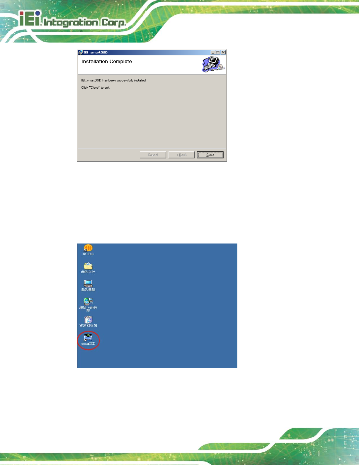
LCD-KIT-F
Page 72
Figure C-5: smartOSD Installation Comp lete
Step 12: Click Close in the screen above.
Step 13: After quick setup is complete, the IEI smartOSD wizard logo appears on the
desktop as shown in the screen below.
Step 14: To access the smartOSD, click the smartOSD wizard logo.Step 0:
C.4 Software Illus tration
The table below shows the smartOSD menu structure for all IEI LCD monitors.
Page 84

LCD-KIT-F
Page 73
NOTE:
To update the display setting status immediately, push the refresh
button on every page
To turn the system on, press ALT + P.
Item Elements
Management
EDID
Image
Display
Color
Save/Load File
Power Management
EDID contains basic information about the monitor and its
capabilities.
Brightness
Contrast
Sharpness
Auto Adjust
Phase
Clock
Auto Color
User Red Gain
User Green Gain
User Blue Gain
Color T emperature
Gamma (disabled in the DM-F Series)
PIP
System
PIP (disabled in the DM-F Series)
PIP Source Input (disabled in the DM-F Series)
PIP Size (disabled in the DM-F Series)
Monitor Power Control
Page 85

LCD-KIT-F
Page 74
Auto Brightness (disabled in the DM-F Series)
Main Source Input (YPbPr, S-Video and CVBS disabled)
Volume (disabled in the DM-F Series)
Factory Presets/OSD Lock/OSD Unlock
Mute (disabled in the DM-F Series)
Table C-1: SmartOSD Menu Structure
Page 86

LCD-KIT-F
Page 75
C.4.1 Manage Page
Figure C-6: Manage Page
Page 87

LCD-KIT-F
Page 76
C.4.2 EDID Page
Figure C-7: EDID Page
Page 88

LCD-KIT-F
Page 77
C.4.3 Ima g e Page
Figure C-8: Image Page
Page 89

LCD-KIT-F
Page 78
C.4.4 Display Page (for analog signal)
Figure C-9: Display Page
Page 90
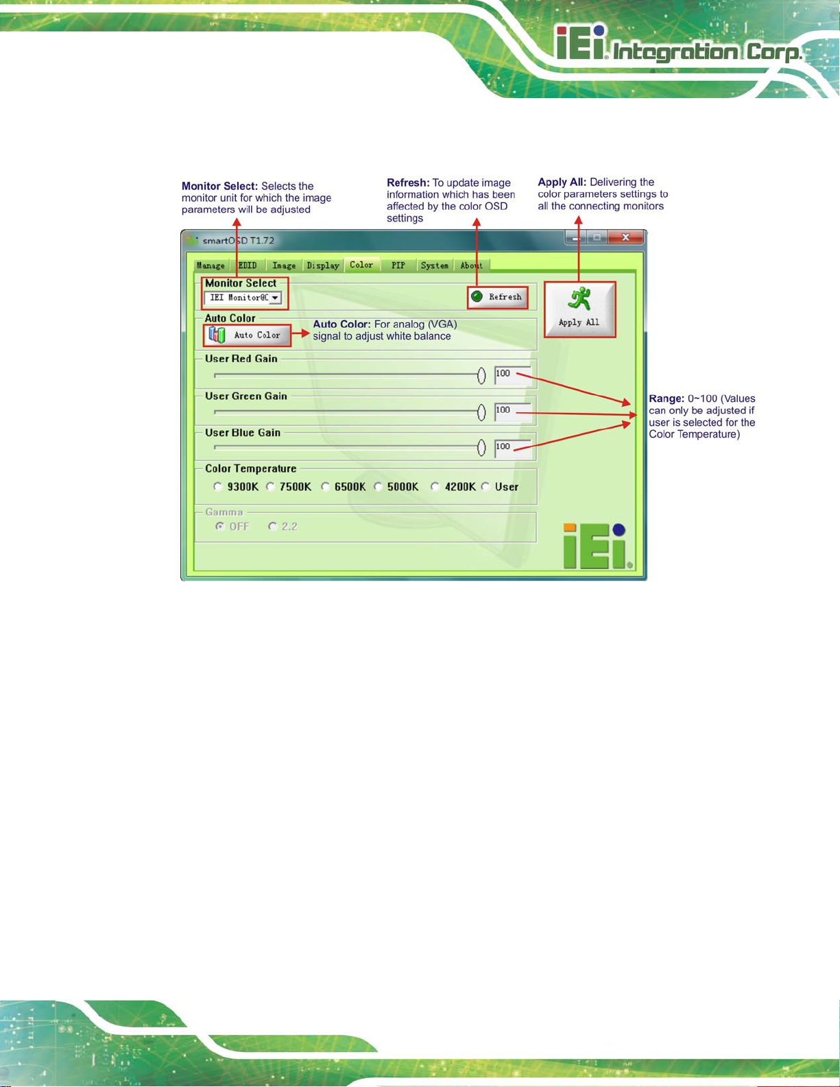
LCD-KIT-F
Page 79
C.4.5 Color Page
Figure C-10: Color Page
Page 91

LCD-KIT-F
Page 80
C.4.6 PIP Page
NOTE:
The functions in the PIP page are only available in the MLCD-KIT
Series and AFOLUX Series monitors.
Figure C-11: PIP Page
Page 92

LCD-KIT-F
Page 81
C.4.7 Sys tem Page
Figure C-12: System Page
NOTE:
Some of the functions in the System Page are only available to some of
the IEI LCD series as following:
Auto Brightness: SRM, MLCD-KIT and AFOLUX series
only
Main Source Input: MLCD-KIT and AFOLUX series only
Volume: AFOLUX series only
Mute: AFOLUX series only
Page 93

LCD-KIT-F
Page 82
C.4.8 About Page
Figure C-13: About Page
Page 94
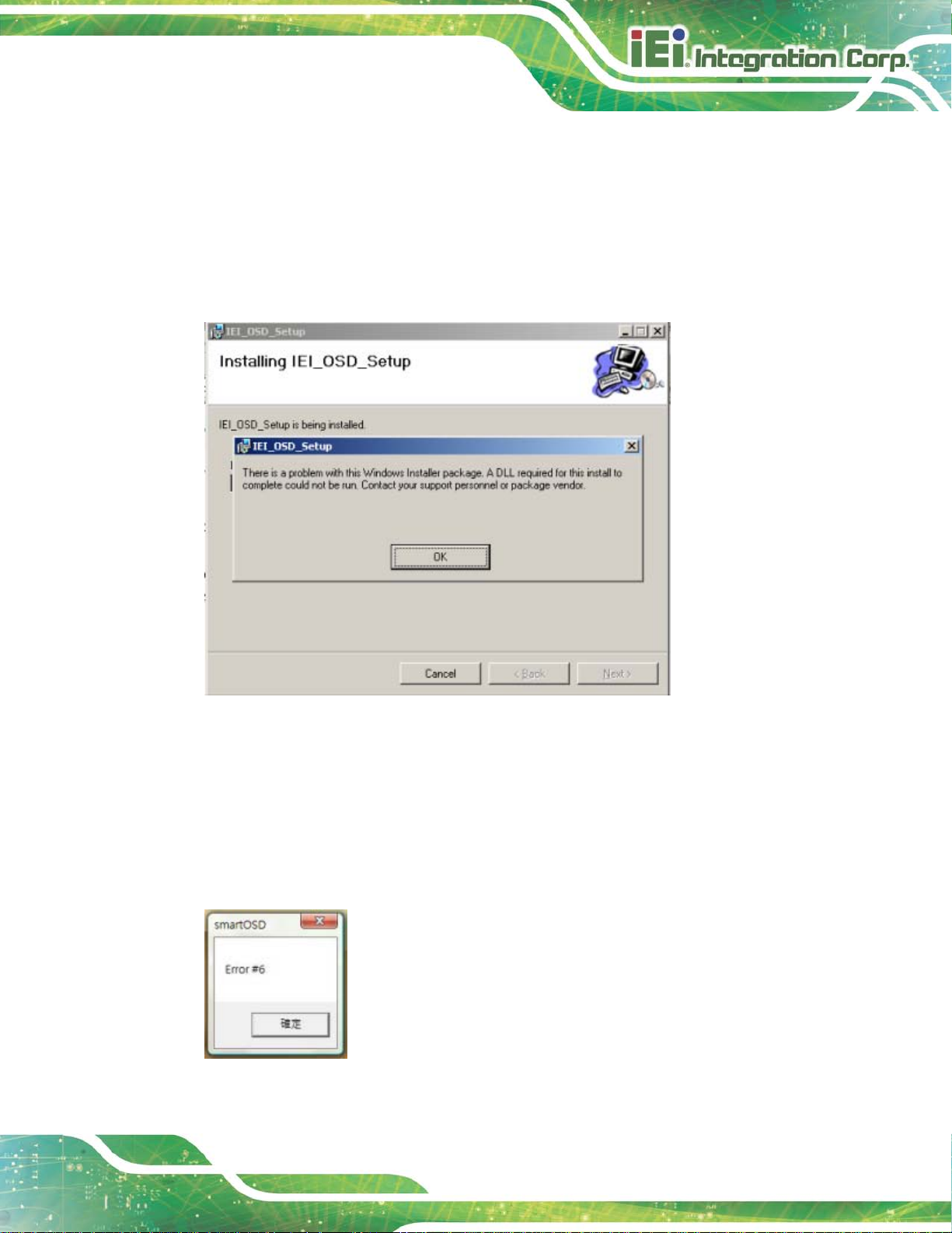
LCD-KIT-F
Page 83
C.5 smartOSD FAQ
For troubleshooting, please see the steps below:
C.5.1 Windows 2000 Installation Failure
Installation fails under Windows 2000 and shows the following image:
Figure C-14: DLL Missing
Solution: Download and install service pac k Windows Installer 3.1
C.5.2 Vista Installation Failure
Installation fail under Vista while showing following image:
Figure C-15: Windows Vista Error
Page 95

LCD-KIT-F
Page 84
Solution: Install SmartOSD.exe as the administrator authority
Figure C-16: Install as Administrator
C.5.3 Model Failur e
The Model Fail error message shown below appears.
Figure C-17: Firmware Incompatibili ty
Solution: SmartOSD only supports firmware version 2.0 and following versions.
Page 96

LCD-KIT-F
Page 85
C.5.4 DDC Port Failur e
The DDC port fail error message shown below appears.
Figure C-18: DDC Port Failure
Solutions:
Check VGA or HDMI cable
Check an IEI monitor is being used
Make sure the version is version 2.3 for the AFOLUX/MDM series and version
1.5 for the DM/ISDM/TDM/SRM/LCD-KIT series that have the SmartOSD
functions
Check if the OSD control status is busy. A busy signal may cause the signal
message for a short time.
Page 97

LCD-KIT-F
Page 86
Appendix
D
D Hazardous Materials
Disclosure
Page 98
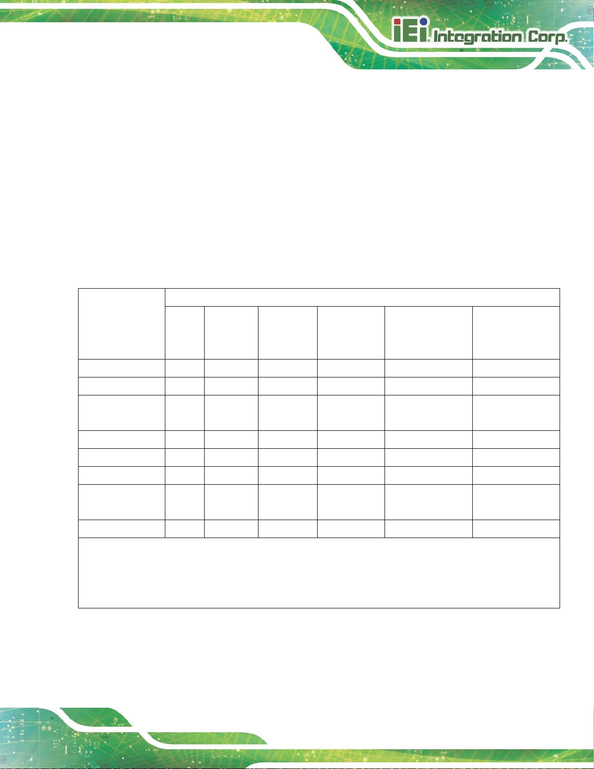
LCD-KIT-F
Page 87
The details provided i n this append ix are to ens ure that the pr oduct is com pliant with the
Peoples Republic of China (China) RoHS stan dards. The table be low acknowledges the
presences of small quantities of certain materials in the product, and is applicable to China
RoHS only.
A label will be place d o n e ach product to indicate the estimated “Environmentally Friendly
Use Period” (EFUP) . This is an estimate of the number of years that t hese substances
would “not leak out or undergo abrupt change.” This product may contain replaceable
sub-assemblies/components which have a shorter EFUP such as batteries and lamps.
These components will be separately marked.
Please refer to the following table.
Part Name Tox ic or Hazard o us Subs tanc es and Elem e nts
Lead
(Pb)
Housing
Display
Printed Circuit
Board
Metal Fasteners
Cable Assembly
Fan Assembly
Power Supply
Assemblies
Battery
O: This tox ic or hazard o us substa nc e is containe d in all of the hom oge neo us m ateri als for the part is be low the limit
requirement in SJ/T11363-2006 (now replaced by GB/T 26572-2011).
X: This toxic or hazardous substance is contained in at least one of the homogeneous materials for this part is above
O O O O O O
O O O O O O
O O O O O O
O O O O O O
O O O O O O
O O O O O O
O O O O O O
O O O O O O
Mercury
(Hg)
Cadmium
(Cd)
Hexavalent
Chromium
(CR(VI))
Polybrominated
Biphenyls
(PBB)
Polybrominated
Diphenyl Ethers
(PBDE)
the limit requirement in SJ/T11363-2006 (now replaced by GB/T 26572-2011).
Page 99

LCD-KIT-F
Page 88
部件名称
有毒有害物质或元素
铅
汞
镉
六价铬
多溴联苯
多溴二苯
醚
壳体
显示
印刷电路板
金属螺帽
电缆组装
风扇组装
电力供应组装
电池
此附件旨在确保本产品符合中国 RoHS 标准。以下表格标示此产品中某有毒物质的含量符
合中国 RoHS标准规定的限量要求。
本产品上会附有”环境友好使用期限”的标签,此期限是估算这些物质”不会有泄漏或突变”的
年限。本产品可能包含有较短的环境友好使用期限的可替换元件,像是电池或灯管,这些元
件将会单独标示出来。
(Pb)
O: 表示该有毒有害物质在该部件所有物质材料中的含量均在 SJ/T 11363-2006 (现由GB/T 26572-2011 取代)
标准规定的限量要求以下。
O O O O O O
O O O O O O
O O O O O O
O O O O O O
O O O O O O
O O O O O O
O O O O O O
O O O O O O
(Hg)
(Cd)
(CR(VI))
(PBB)
(PBDE)
X: 表示该有毒有害物质至少在该部件的某一均质材料中的含量超出 SJ/T 11363-2006 (现由 GB/T
26572-2011取代) 标准规定的限量要求。
 Loading...