

Page 1

LCD KIT Series Monito
r
Page 1
Page 2

REVISION HISTORY
Title LCD-KIT Series Monitor User Manual
Revision Number Description Date of Issue
1.0 Initial release September 2006
ABOUT THIS MANUAL
This document covers the description and installation instructions for the LCD-KIT Series
Monitors. The monitors in this series include the LCD-KIT190G, LCD-KIT170G,
LCD-KIT150G, LCD-KIT121G, LCD-KIT104G, LCD-KIT84G and LCD-KIT65G.
COPYRIGHT NOTICE
This document is copyrighted 2006, by IEI Technology Corp. All rights are reserved. IEI
Technology Corp. reserves the rights to alter the products described in this manual at any
time without prior notice.
This document contains proprietary information protected by copyright. All rights are
reserved. No part of this manual may be reproduced by any mechanical, electronic, or
other means in any form without prior written permission of the manufacturer.
Information provided in this manual is intended to be accurate and reliable. However, IEI
Technology Corp. assumes no responsibility for use of this manual, nor for any
infringements upon the rights of third parties, which may result from such use.
Page 2
IEI® Technology, Corp.
Page 3

LCD KIT Series Monito
r
SAFETY PRECAUTIONS
Prior to installing, moving, and modifying the monitor, make sure the power is
turned off and the power cord is disconnected.
Do not apply voltage levels that exceed the specified voltage range. Doing so will
cause fire or an electrical shock.
Electric shocks can occur if the panel is opened. Do not drop or insert any objects
into the ventilation openings of the monitor.
Only qualified engineers from certified system integrators or VARs are allowed to
make necessary functional modifications to the monitor, e.g., adding a touch
panel. IEI offers the customization service on a pre-order basis.
Designs with stand-alone and fault-tolerant hardware considerations should be
implemented using the series models as a critical alarm or production line control.
If considerable amount of dust, water, or fluids entered the monitor, turn off the
power supply immediately, unplug the power cord, and contact the monitor
vendor.
Explosions may occur with installations in environments where flammable gases
are present.
Fault-tolerant and failsafe designs should be implemented with the use of the
series models on transportation vehicles, ships, safety/security devices, or
medical devices not related to life-support functionalities. Users/integrators should
take the responsibility for implementations with adequate levels of reliability and
safety.
FURTHER PRECAUTIONS
Do not drop the monitor against a hard surface. Doing so will damage the display.
Do not strike or exert excessive force onto the LCD panel.
Touching the LCD panel using a sharp object will damage the LCD panel.
Avoid environments exposed to direct sunlight, dust, or chemical vapors.
The ambient temperature of the installation site should be observed and
controlled to avoid overheating the monitor.
Page 3
Page 4

A
Condensation might form inside the monitor chassis if exposed to sudden
changes in temperature.
Carefully route the power cord so that people cannot step on it. Do not place
anything over the power cord.
If the equipment should be left unused for an extended period of time, disconnect
it from the power source to avoid damage by transient over-voltage.
If any of the following situations arise, have the equipment checked by qualified
service personnel:
o The power cord or plug is damaged.
o Liquid has penetrated into the equipment.
o The equipment has been exposed to moisture.
o The equipment does not work properly, or cannot be made to work
according to the user manual.
o The equipment has been dropped and damaged.
o The equipment shows obvious signs of damage.
WARNING!
ny changes or modifications made to the equipment that are not
expressly approved by the relevant standards could void the authority to
operate the equipment.
ADDITIONAL INFORMATION AND ASSISTANCE
MAINTENANCE AND CLEANING
Prior to cleaning any part or component of the monitor, please read the details below.
Except for the properly installed front LCD panel, never spray or squirt liquids
directly onto any other component. To clean the LCD panel, please rub it with a
piece of soft dry cloth or a slightly moistened cloth.
The interior of the LCD monitor does not require cleaning. Keep fluids away from
the LCD monitor interior.
Page 4
IEI® Technology, Corp.
Page 5

LCD KIT Series Monito
r
Be cautious of all small removable components when vacuuming the monitor.
Turn the system off before cleaning the LCD monitor.
Never drop any objects or liquids through the openings of the LCD monitor.
Be cautious of any possible allergic reactions to solvents or chemicals used when
cleaning the monitor.
Avoid eating, drinking and smoking within vicinity of the monitor.
CLEANING TOOLS
Some components in the monitor may only be cleaned using a product specifically
designed for the purpose. In such case, the product will be explicitly mentioned in the
cleaning tips. Below is a list of items to use when cleaning the computer or computer
peripherals.
Cloth – Although paper towels or tissues can be used, a soft, clean piece of cloth
is recommended when cleaning the monitor.
Water or rubbing alcohol – A cloth moistened with water or rubbing alcohol can
be used to clean the monitor.
Using solvents – The use of solvents is not recommended when cleaning the
monitor as they may damage the plastic parts.
Vacuum cleaner – Using a vacuum specifically designed for computers is one of
the best methods of cleaning the monitor. Over dust and dirt can restrict the
airflow in a computer and cause circuitry to corrode.
Cotton swabs - Cotton swaps moistened with rubbing alcohol or water are
excellent tools for wiping hard to reach areas.
Foam swabs - Whenever possible, it is best to use lint free swabs such as foam
swabs for cleaning.
ESD PRECAUTIONS
Observe all conventional anti-ESD methods while handling the components contained
within the LCD should the need arise for adding a function. The use of a grounded wrist
Page 5
Page 6

strap and an anti-static work pad is recommended. Avoid dust and debris or other
static-accumulating materials in the work area.
CONVENTIONS USED IN THIS MANUAL
WARNING!
Warnings appear where overlooked details may cause damage to the equipment or result
in personal injury. Warnings should be taken seriously. Warnings are easy to recognize.
The word “warning” is written as “WARNING,” both capitalized and bold and is followed by
text in italics. The italicized text is the warning message.
CAUTION!
Cautionary messages should also be heeded to helps reduce the chance of losing data or
damaging the system. Cautions are easy to recognize. The word “caution” is written as
“CAUTION,” both capitalized and bold and is followed by text in italics. The italicized text
is the cautionary message.
NOTE:
These messages inform the reader of essential but non-critical information. These
messages should be read carefully as any directions or instructions contained therein can
helps avoid making mistakes. Notes are easy to recognize. The word “note” is written as
“NOTE,” both capitalized and bold and is followed by text in italics. The italicized text is the
cautionary message.
Lists
Bulleted Lists: Bulleted lists are statements of non-sequential facts that can be read in
any order. Each statement is preceded by a round black dot “•” or bullets in other shapes.
Page 6
Numbered Lists: Numbered lists describe sequential steps should be followed in order.
IEI® Technology, Corp.
Page 7

LCD KIT Series Monito
r
Table of Contents
1 INTRODUCTION...................................................................................................18
LCD-KIT SERIES MONITOR OVERVIEW................................................................... 19
1.1
1.1.1 Standar d Features............................................................................................ 19
1.1.2 Model Variations............................................ .................................................. 19
1.2
APPLICATIONS AND FEATURES.................................................................................. 19
1.2.1 LCD-KIT Series Monitor Applications ..................................................... ....... 19
1.2.2 LCD-KIT Series Monitor Features.................................................................. 20
1.3
EXTERNAL OVERVIEW.............................................................................................. 20
1.3.1 Front View......................................................... ... ............................................ 20
1.3.2 Rear View ............................................... ........................................... ............... 21
1.3.3 Connectors................... .. ...... ..... ... ..... ..... ... ..... ...... .. ...... ..... ... ..... ... ..... ..... ... ..... ..22
1.3.4 AD Board .................................................. ........ ........... ........ .......... ........ ..........22
1.4
SERIES SPECIFICATIONS............................................................................................ 23
1.5
CERTIFICATIONS .......................................................................................................25
2 MECHANICAL OVERVIEW...............................................................................26
2.1 INTRODUCTION......................................................................................................... 27
REAR PANEL............................................................................................................. 27
2.2
2.2.1 Rear Panel Variants.......................... ........................................... .................... 27
2.2.2 Rear Panel Variant 1................................................. ... ....................................27
2.2.3 Rear Panel Variant 2................................................. ... ....................................28
2.3
CONNECTOR PANEL..................................................................................................29
2.3.1 A v ailable Connectors............................................. ........... ........ ........... ........ ....29
2.3.2 Variant 1 Connectors ........................................... ........ .......... ........... ........ .......29
2.3.3 Variant 2 Connectors ........................................... ........ .......... ........... ........ .......30
2.4
PHYSICAL DIMENSIONS............................................................................................ 30
2.4.1 General Physical Dimensions........................................... ..... ... ..... ... ..... ...... .. ..30
2.4.2 LCD-KIT190G Physical Dimensions............................................................. ..31
2.4.3 LCD-KIT170G Physical Dimensions............................................................. ..32
2.4.4 LCD-KIT150G Physical Dimensions............................................................. ..33
2.4.5 LCD-KIT121G Physical Dimensions............................................................. ..34
Page 7
Page 8

2.4.6 LCD-KIT104G Physical Dimensions............................................................. ..35
2.4.7 LCD-KIT84G Physical Dimensions....................... ..........................................36
2.4.8 LCD-KIT65G Physical Dimensions................................................................. 37
2.5
MOUNTING OPTIONS ................................................................................................ 38
3 LCD SPECIFICATIONS .......................................................................................39
3.1 LCD SPECIFICATIONS...............................................................................................40
3.1.1 LCD Overview .......................................................... ... ....................................40
3.1.2 LCD-KIT190G LCD Specifications............................................... ... ............... 41
3.1.3 LCD-KIT170G LCD Specifications............................................... ... ............... 42
3.1.4 LCD-KIT150G LCD Specifications............................................... ... ............... 43
3.1.5 LCD-KIT121G LCD Specifications............................................... ... ............... 44
3.1.6 LCD-KIT104G LCD Specifications............................................... ... ............... 45
3.1.7 LCD-KIT84G LCD Specifications............................................... .. .................. 46
3.1.8 LCD-KIT65G LCD Specifications............................................... .. .................. 47
3.2
POWER ADAPTERS....................................................................................................48
4 AD BOARDS....................... .. ........................................... .......................................49
4.1 AD BOARD OVERVIEW............................................................................................. 50
AV-9350 AD BOARD................................................................................................ 50
4.2
4.2.1 AV-9350 AD Board Overview.......................................................................... 50
4.2.2 AV-9350 AD Board Connectors ....................................................................... 50
4.2.3 AV-9350 AD Board Layout............................................................................... 51
4.2.4 AV-9350 Peripheral Interface Connectors....................................................... 51
4.2.5 AV-9350 Rear Panel Connectors..................................................................... 52
4.2.6 A V-9350 Onboard Jumper................................................................................52
4.2.7 A V-9350 Internal Peripheral Connectors........................................................ 53
4.2.8 5V Power Connector......................................................... ..... ...... .. ...... .. ...... ....53
4.2.9 Debugged Port Connector........................................................... .. .................. 55
4.2.10 External OSD and LED Indication Connector.............................................. 56
4.2.11 Serial Communications Connector .................................... .. .......................... 58
4.2.12 TTL Output Connector................................................................................... 59
4.2.13 VGA Connector............................................... ........... ........ .......... ........ ..........61
4.2.14 A V-9350 External (Rear Panel) Connectors.................................................. 62
4.2.15 DC 12V Connector..................................... .. ........................................... ....... 62
4.2.16 RS232 Serial Connector................................................................................. 63
Page 8
IEI® Technology, Corp.
Page 9

LCD KIT Series Monito
r
4.2.17 OSD Control Buttons .....................................................................................64
4.2.18 VGA Connector............................................... ........... ........ .......... ........ ..........65
4.2.19 AV-9350 Onboard Jumper.............................................................................. 66
4.2.20 LCD Panel (TTL) Voltage Select Jumper................................... .................... 67
4.3
AV-5350 AD BOARD................................................................................................ 68
4.3.1 AV-5350 AD Board Overview.......................................................................... 68
4.3.2 AV-5350 AD Board Connectors ....................................................................... 68
4.3.3 AV-5350 AD Board Layout............................................................................... 69
4.3.4 AV-5350 Peripheral Interface Connectors....................................................... 70
4.3.5 AV-5350 Rear Panel Connectors..................................................................... 70
4.3.6 A V-5350 Onboard Jumper................................................................................70
4.3.7 A V-5350 Internal Peripheral Connectors........................................................ 71
4.3.8 5V Power Connector......................................................... ..... ...... .. ...... .. ...... ....71
4.3.9 Backlight Inverter Connector ........................................ ... ............................... 72
4.3.10 External OSD and LED Indication Connector.............................................. 73
4.3.11 LVDS Output Connector ................................................................................ 74
4.3.12 VGA Connector............................................... ........... ........ .......... ........ ..........75
4.3.13 A V-5350 External (Rear Panel) Connectors.................................................. 76
4.3.14 DC 12V Connector..................................... .. ........................................... ....... 77
4.3.15 VGA Connector............................................... ........... ........ .......... ........ ..........77
4.3.16 AV-5350 Onboard Jumper.............................................................................. 78
4.3.17 LCD Panel Voltage Select Jumper................................................................. 79
4.4
AV-5300 AD BOARD................................................................................................ 80
4.4.1 AV-5300 AD Board Overview.......................................................................... 80
4.4.2 AV-5300 AD Board Connectors ....................................................................... 81
4.4.3 AV-5300 AD Board Layout............................................................................... 82
4.4.4 AV-5300 Peripheral Interface Connectors....................................................... 83
4.4.5 AV-5300 Rear Panel Connectors..................................................................... 83
4.4.6 AV-5300 Onboard Jumpers.............................................................................. 84
4.4.7 A V-5300 Internal Peripheral Connectors........................................................ 84
4.4.8 5V Power Connector......................................................... ..... ...... .. ...... .. ...... ....84
4.4.9 Backlight Inverter Connector ........................................ ... ............................... 86
4.4.10 DC/DC Power Connector..............................................................................87
4.4.11 Debugged Port Connector ............................................................................. 89
4.4.12 External OSD and LED Indication Connector.............................................. 91
4.4.13 LVDS Output Connector................................................................................93
Page 9
Page 10

4.4.14 VGA Connector............................................... ........... ........ .......... ........ ..........95
4.4.15 A V-5300 External (Rear Panel) Connectors.................................................. 97
4.4.16 DC 12V Connector..................................... .. ........................................... ....... 98
4.4.17 VGA Connector............................................... ........... ........ .......... ........ ..........99
4.4.18 DVI-D Connector....................................................................................... .... 99
4.4.19 AV-5300 Onboard Jumpers.......................................................................... 101
4.4.20 LCD Panel Power Input Jumper.................................................................. 102
4.4.21 LCD Panel Voltage Select Jumper............................................................... 103
5 INSTALLATION .................................................................................................. 104
INSTALLATION PRECAUTIONS................................................................................. 105
5.1
UNPACKING............................................................................................................ 106
5.2
5.2.1 Packaging ................................................. ... .................................................. 106
5.2.2 Unpacking Procedure ............................ ... ..... ...... .. ...... ..... ... ..... ..... ... ..... ...... ..106
5.2.3 Packing List ......................................................... .. ........................................107
5.3
PRE-INSTALLATION PREPARATION .......................................................................... 107
5.3.1 Tools....................................... ........ ........... ........ ........... ........ .......... ........... .....107
5.4
CONNECTORS ......................................................................................................... 107
5.4.1 VGA Connector...................................................... ........... ........ ........... ..........108
5.4.2 DVI-D Connector................................................... ... ..... ...... .. ...... .. ...... ..... ... ..108
5.4.3 12V Power Connector............................................... ... .................................. 109
5.5 MOUNTING THE LCD-KIT SERIES MONITOR.........................................................109
6 ON-SCREEN-DISPLAY (OSD) CONTROLS....................................................110
6.1 USER MODE OSD STRUCTURE................................................................................111
6.1.1 OSD Buttons......................... .. ...... .. ...... ..... ... ..... ..... ... ..... ... ..... ...... .. ...... .. ...... ...111
6.1.2 OSD Menu Structure – All Models Except LCD-KIT65G......................... ..... .112
6.1.3 LCD-KIT65G OSD Menu Structure....................................... .........................114
6.2 USING THE OSD......................................................................................................115
6.2.1 Main Display Featur es................................................. ...................................115
6.2.2 Color.............................. ...... ..... ... ..... ..... ... ..... ... ..... ...... .. ...... .. ...... ..... ... ..... ..... .116
6.2.3 Language...................... .. .................................................................................117
6.2.4 OSD Configurations..................... ..... ... ..... ..... ... ..... ...... .. ...... .. ...... ..... ... ..... ... ...117
6.2.5 Signal ................................................ ..... ... ..... ...... .. ...... .. ...... ..... ... ..... ... ..... ..... .119
6.2.6 Backlight........................................................... ... ........................................ .. .119
A CERTIFICATIONS.............................................................................................. 121
Page 10
IEI® Technology, Corp.
Page 11

LCD KIT Series Monito
r
A.1
ROHS COMPLIANT................................................................................................122
B INDEX....................................................................................................................123
Page 11
Page 12

List of Figures
Figure 1-1: Typical LCD-KIT Front View....................................................................21
Figure 1-2: Typical LCD-KIT Rear View.....................................................................22
Figure 1-3: Typical LCD-KIT Connectors..................................................................22
Figure 1-4: AV-5300 AD Board...................................................................................23
Figure 2-1: Rear Panel Variant 1................................................................................28
Figure 2-2: Rear Panel Variant 2................................................................................29
Figure 2-3: LCD-KIT190G Physical Dimensions (millimeters)................................31
Figure 2-4: LCD-KIT170G Physical Dimensions (millimeters)................................32
Figure 2-5: LCD-KIT150G Physical Dimensions (millimeters)................................33
Figure 2-6: LCD-KIT121G Physical Dimensions (millimeters)................................34
Figure 2-7: LCD-KIT104G Physical Dimensions (millimeters)................................35
Figure 2-8: LCD-KIT84G Physical Dimensions (millimeters)..................................36
Figure 2-9: LCD-KIT65G Physical Dimensions (millimeters)..................................37
Figure 4-1: AV-9350 AD Board Overview..................................................................50
Figure 4-2: Connector and Jumper Locations .........................................................51
Figure 4-3: 5V Power Connector Location ........................................... ....................54
Figure 4-4: Debugged Port Connector Location......................................................55
Figure 4-5: External OSD and LED Indication Connector Location.......................57
Figure 4-6: Serial Communications Connector Location............................... .........58
Figure 4-7: TTL Output Connector Location ............................................................60
Figure 4-8: VGA Connector Location........................................................................61
Figure 4-9: AV-9350 External (Rear Panel) Connectors..........................................62
Figure 4-10: RS232 Serial Connector Pinout Locations..........................................63
Page 12
Figure 4-11: VGA Connector Pinout Locations........................................................65
Figure 4-12: Jumpers..................................................................................................66
Figure 4-13: Jumper Location....................................................................................66
IEI® Technology, Corp.
Page 13

LCD KIT Series Monito
r
Figure 4-14: AV-5350 AD Board Overview................................................................68
Figure 4-15: Connector and Jumper Locations.......................................................69
Figure 4-16: 5V Power Connector Location ..................................... ........................71
Figure 4-17: Backlight Inverter Connector Location...............................................72
Figure 4-18: External OSD and LED Indication Connector Location.....................73
Figure 4-19: LVDS Output Connector Location.......................................................75
Figure 4-20: VGA Connector Location......................................................................76
Figure 4-21: AV-5350 External (Rear Panel) Connectors........................................77
Figure 4-22: VGA Connector Pinout Locations........................................................78
Figure 4-23: Jumpers..................................................................................................78
Figure 4-24: Jumper Location....................................................................................79
Figure 4-25: AV-5300 AD Board Overview................................................................80
Figure 4-26: Connector and Jumper Locations.......................................................82
Figure 4-27: 5V Power Connector Location ..................................... ........................85
Figure 4-28: Backlight Inverter Connector Location...............................................87
Figure 4-29: DC/DC Power Connector Location ......................................................89
Figure 4-30: Debugged Port Connector Location....................................................91
Figure 4-31: External OSD and LED Indication Connector Location.....................93
Figure 4-32: LVDS Output Connector Location.......................................................95
Figure 4-33: VGA Connector Location......................................................................97
Figure 4-34: AV-5300 External (Rear Panel) Connectors........................................98
Figure 4-35: VGA Connector Pinout Locations........................................................99
Figure 4-36: DVI-D Connector Pinout Locations................................................... 100
Figure 4-37: Jumpers............................................................................................... 101
Figure 4-38: Jumper Location................................................................................. 102
Figure 5-1: VGA Connector..................................................................................... 108
Figure 5-2: DVI-D Connector................................................................................... 109
Figure 5-3: 12V Power Connector........................................................................... 109
Figure 6-1: OSD Control Buttons for All Models Except LCD-KIT65G ............... 111
Figure 6-2: LCD-KIT65G OSD Control Buttons..................................................... 112
Page 13
Page 14

Figure 6-3: Main Display Features.......................................... ... .... .... .... ... .... .... .... .. 115
Figure 6-4: Color Options........................................................................................ 116
Figure 6-5: Language Menu .................................................................................... 117
Figure 6-6: OSD Configurations Menu................................................................... 118
Figure 6-7: Signal Menu........................................................................................... 119
Figure 6-8: Backlight Menu..................................................................................... 119
Page 14
IEI® Technology, Corp.
Page 15

LCD KIT Series Monito
r
List of Tables
Table 1-1: LCD-KIT Series Specifications.................................................................24
Table 2-1: Rear Panel Variants...................................................................................27
Table 2-2: General Physical Dimensions..................................................................30
Table 2-3: Mounting Holes .........................................................................................38
Table 3-1: LCD-KIT190G LCD Specifications...........................................................41
Table 3-2: LCD-KIT170G LCD Specifications...........................................................42
Table 3-3: LCD-KIT150G LCD Specifications...........................................................43
Table 3-4: LCD-KIT121G LCD Specifications...........................................................44
Table 3-5: LCD-KIT104G LCD Specifications...........................................................45
Table 3-6: LCD-KIT84G LCD Specifications.............................................................46
Table 3-7: LCD-KIT65G LCD Specifications.............................................................47
Table 3-8: Power Adapter Specifications..................................................................48
Table 4-1: AV-9350 Peripheral Interface Connectors ..............................................52
Table 4-2: AV-9350 Rear Panel Connectors .............................................................52
Table 4-3: AV-9350 Onboard Jumper........................................................................52
Table 4-4: 5V Power Connector Pinouts...................................................................53
Table 4-5: Debugged Port Connector Pinouts .........................................................55
Table 4-6: External OSD and LED Indication Connector Pinouts ..........................56
Table 4-7: Serial Communications Connector Pinouts...........................................58
Table 4-8: TTL Output Connector Pinouts................................................................59
Table 4-9: VGA Connector Pinouts ...........................................................................61
Table 4-10: DC 12V Connector Pinouts.....................................................................62
Table 4-11: RS232 Serial Connector Pinouts ...................................................... .... .63
Table 4-12: OSD Control Button JP1 Pinouts ...................................... ....................64
Table 4-13: OSD Control Button JP2 Pinouts ...................................... ....................64
Table 4-14: OSD Control Button JP3 Pinouts ...................................... ....................64
Page 15
Page 16

Table 4-15: OSD Control Button JP4 Pinouts ...................................... ....................64
Table 4-16: VGA Connector Pinouts ............................................. .... .... ... ........ .... .... .65
Table 4-17: LCD Panel (TTL) Voltage Select Jumper Settings ...............................67
Table 4-18: AV-5350 Peripheral Interface Connectors ............................................70
Table 4-19: AV-5350 Rear Panel Connectors ...........................................................70
Table 4-20: AV-5350 Onboard Jumper......................................................................70
Table 4-21: 5V Power Connector Pinouts.................................................................71
Table 4-22: Backlight Inverter Connector Pinouts...................................................72
Table 4-23: External OSD and LED Indication Connector Pinouts ........................73
Table 4-24: LVDS Output Connector Pinouts...........................................................74
Table 4-25: VGA Connector Pinouts ............................................. .... .... ... ........ .... .... .76
Table 4-26: DC 12V Connector Pinouts.....................................................................77
Table 4-27: VGA Connector Pinouts ............................................. .... .... ... ........ .... .... .78
Table 4-28: LCD Panel Voltage Select Jumper Settings .........................................79
Table 4-29: AV-5300 Peripheral Interface Connectors ............................................83
Table 4-30: AV-5300 Rear Panel Connectors ...........................................................83
Table 4-31: AV-5300 Onboard Jumpers....................................................................84
Table 4-32: 5V Power Connector Pinouts.................................................................84
Table 4-33: Backlight Inverter Connector Pinouts...................................................86
Table 4-34: DC/DC Power Connector Pinouts..........................................................88
Table 4-35: Debugged Port Connector Pinouts .......................................................90
Table 4-36: External OSD and LED Indication Connector Pinouts ........................92
Table 4-37: LVDS Output Connector Pinouts...........................................................94
Table 4-38: VGA Connector Pinouts ............................................. .... .... ... ........ .... .... .96
Table 4-39: DC 12V Connector Pinouts.....................................................................98
Table 4-40: VGA Connector Pinouts ............................................. .... .... ... ........ .... .... .99
Table 4-41: DVI-D Connector Pinouts .................................................................... 100
Page 16
Table 4-42: LCD Panel Power Input Jumper Settings .......................................... 103
Table 4-43: LCD Panel Voltage Select Jumper Settings ...................................... 103
Table 5-1: Rear Panel Connectors.......................................................................... 108
IEI® Technology, Corp.
Page 17

LCD KIT Series Monito
r
Table 5-2: VGA Connector Pinouts ........................................................................ 108
Table 5-3: DVI-D Connector Pinouts ...................................................................... 109
Table 6-1: OSD Menus – All Models Except LCD-KIT65G.................................... 113
Table 6-2: LCD-KIT65G OSD Menus....................................................................... 115
Page 17
Page 18

Chapter
1
1 Introduction
Page 18
IEI® Technology, Corp.
Page 19

r
1.1 LCD-KIT Series Monitor Overview
The LCD-KIT series monitor is the latest member of IEI’s line of sophisticated LCD
designs, and it has been improved to be RoHS compliant. It is designed to fit industrial
automation, or any other applications that require minimum installation space and
flexible configuration. Flexible analog or digital interfaces are provided for ease of
connection with a management computer. If remote/non-attentive control is preferred,
RS-232 or USB interfaces can be used with customized adapter cables.
1.1.1 Standard Features
All the base models listed in Section 1.2.1 have the following standard features
LCD monitor
LCD KIT Series Monito
OSD controls
VGA
Robust metal chassis
RoHS compliant
1.1.2 Model Variations
The LCD-KIT series offers the following model variations.
LCD-KIT65G: 6.5” LCD screen
LCD-KIT65GH: 6.5” LCD screen + high luminance
LCD-KIT84G: 8.4” LCD screen
LCD-KIT84GH: 8.4” LCD screen + high luminance
LCD-KIT104G: 10.4” LCD screen
LCD-KIT104GH: 10.4” LCD screen + high luminance
LCD-KIT121G: 12.1” LCD screen
LCD-KIT150G: 15” LCD screen
LCD-KIT170G: 17” LCD screen
LCD-KIT190G: 19” LCD screen
1.2 Applications and Features
1.2.1 LCD-KIT Series Monitor Applications
Page 19
Page 20

IEI’s series of LCD kits are designed for system manufacturers, integrators, or
value-added resellers that want to provide all the performance, quality and reliability of an
LCD display solution at a cost effective price. IEI’s LCD kits offer additional components
such as cables, an inverter and power supply with controller interfaces that include VGA
and DVI.
1.2.2 LCD-KIT Series Monitor Features
Some of the features of the LCD-KIT series monitor include:
Analog VGA interface supports most general system boards
Over 300 cd/m2 high brightness and 50,000 hrs MTFB long lifetime panel
Advanced thermal and air-flow design
Supports panel mounting
12V DC power input via adapter
Long product life support
RoHS compliant
1.3 External Overview
The following sections describe the physical layout of the LCD-KIT series monitors.
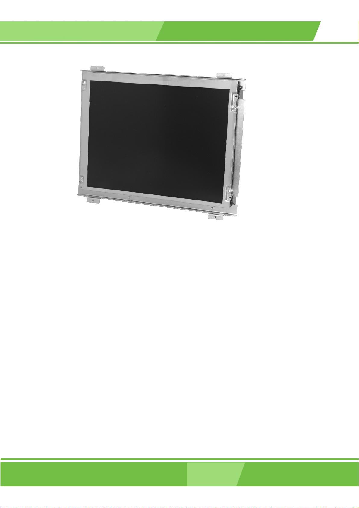
1.3.1 Front View
The front of the LCD-KIT series monitor is a flat panel TFT LCD screen attached to a
metal chassis. Figure 1-1 shows a typical LCD-KIT front view.
Page 20
IEI® Technology, Corp.
Page 21
LCD KIT Series Monito
r
Figure 1-1: Typical LCD-KIT Front View
1.3.2 Rear View
The rear of the LCD-KIT series monitor is a metal chassis. An on screen display (OSD)
control button panel, if present, is located vertically on the left side of the chassis with the
following control buttons:
LCD On/Off
Auto
Left
Right
Menu
The OSD panel also has one power LED.
Figure 1-2 shows a typical LCD-KIT rear panel.
Page 21
Page 22

Figure 1-2: Typical LCD-KIT Rear View
1.3.3 Connectors
Each LCD-KIT series monitor has a number of interface connectors on either the top or
right panel of the chassis (when viewing the rear panel). Figure 1-3 shows a typical
LCD-KIT connector panel. Each model may include or exclude additional connectors.
Refer to Section 2.3 for listings of LCD-KITs and their connectors. All connectors are fully
described in Section 5.4.
Figure 1-3: Typical LCD-KIT Connectors
Page 22
1.3.4 AD Board
IEI® Technology, Corp.
Page 23

LCD KIT Series Monito
r
The LCD-KIT series monitor AD boards provide a wide variety of control interfaces,
receiving and managing signals from a CPU card through cabling. Figure 1-4 shows the
AV-5300 AD board as a sample of a typical AD board for the LCD-KIT series monitor.
Refer to Chapter 4 for a complete description of AD boards and their connectors.
Figure 1-4: AV-5300 AD Board
1.4 Series Specifications
Table 1-1 shows the LCD-KIT Series specifications.
LCD-KIT 65G 84G 104G 121G 150G 170G 190G
LCD Type 6.5" TFT 8.4" TFT 10.4" TFT 12.1" TFT 15" TFT 17" TFT 19" TFT
Page 23
Page 24

Input
Interface
VGA VGA + DVI-D
Max.
640x480 800x600 1024x768 1280x1024
Resolution
Backlight
50,000 Hrs
MTBF
Contrast 450:1 500:1 400:1 500:1 700:1
LCD Color 262K 16.2M
Brightness
400/500 220/450 230/400 400 350 300
(cd/m2)
7F700-
PLCD0312101
AG-RS
)
(230 cd/m
or
7F700-
PLCD02102G-RS
)
(400 cd/m
2
2
)
)
7F700-
QF82V4-
RS
7F700-
QF117V116-
RS
7F700-
PLCD2817418-
RS
Inverter
7F700-
LV12ETG-RS
(400 cd/m
LV12EAG-RS
(500 cd/m
2
or
7F700-
2
7F700-
LV1401TG-RS
(220 cd/m
)
or
7F700-
LCD19062C-RS
(450 cd/m
)
2
2
AD Board AV-9350 AV-5350 AV-5300
Power Adapter
25W
63000-UP0251E12PL02-RS
Chassis Heavy-duty steel
130/110
View Angle
140/120
or
120/100 140/110 120/100 140/130
(H / V)
120/100
OSD function Yes
Mounting Panel
Dimension
(WxHxD)
(mm)
203 x
121 x
34
234 x
147 x
35.3
242.2 x
209 x
33.6
294 x
240.7 x
42
Operation
0~50°C
Temperature
Table 1-1: LCD-KIT Series Specifications
45W
63000-UP0451E12P81L-RS
364.1 x
262.5 x
41.9
390.4 x
300 x
46.9
427.9 x
327.4 x
48.4
Page 24
IEI® Technology, Corp.
Page 25

r
1.5 Certifications
All LCD-KIT series monitor models comply with the following international standards:
RoHS
For a more detailed description of these standards, please refer to Appendix A.
LCD KIT Series Monito
Page 25
Page 26

Chapter
2
2 Mechanical Overview
Page 26
IEI® Technology, Corp.
Page 27

r
2.1 Introduction
This chapter describes the general mechanical overview of the LCD-KIT series monitors
including rear panel variations, available interfaces and overall dimensions.
2.2 Rear Panel
The rear panel of the LCD-KIT series monitor is comprised of a metal chassis with an OSD
control panel.
2.2.1 Rear Panel Variants
Table 2-1 shows the rear panel variants for the LCD-KIT series monitor.
LCD KIT Series Monito
Model OSD Control Panel Location
LCD-KIT190G
LCD-KIT170G
LCD-KIT150G
Vertically along the left side of the rear panel. 1
LCD-KIT121G
LCD-KIT104G
LCD-KIT84G
LCD-KIT65G In line along the bottom of the rear panel. 2
Table 2-1: Rear Panel Variants
Variant
Number
2.2.2 Rear Panel Variant 1
The following models of the LCD-KIT series monitor have an OSD control panel located
vertically along the left side of the rear panel:
LCD-KIT190G
LCD-KIT170G
Page 27
Page 28

LCD-KIT150G
LCD-KIT121G
LCD-KIT104G
LCD-KIT84G
Figure 2-1 shows the location of the rear panel variant 1 OSD controls.
Figure 2-1: Rear Panel Variant 1
2.2.3 Rear Panel Variant 2
The following model of the LCD-KIT series monitor has OSD control buttons located on
the bottom of the rear panel:
LCD-KIT65G
Figure 2-2 shows the location of the rear panel variant 2 OSD controls.
Page 28
IEI® Technology, Corp.
Page 29

LCD KIT Series Monito
r
Figure 2-2: Rear Panel Variant 2
2.3 Connector Panel
All external peripheral interface connectors are located on the rear panel of the LCD-KIT
series monitor. The following sections describe the rear panel variants and their
associated connectors.
2.3.1 Available Connectors
There are a number of rear panel peripheral device connectors available for the LCD-KIT
series monitor.
VGA connector
DVI-D connector
12V power connector
2.3.2 Variant 1 Connectors
The following is a list of the bottom panel peripheral device connectors used on the
LCD-KIT65G, LCD-KIT84G and LCD-KIT104G series monitor.
VGA connector
12V power connector
Page 29
Page 30

2.3.3 Variant 2 Connectors
The following is a list of the bottom panel peripheral device connectors used on the
LCD-KIT121G, LCD-KIT150G, LCD-KIT170G and LCD-KIT190G series monitor.
VGA connector
DVI-D connector
12V power connector
2.4 Physical Dimensions
The following sections describe the physical dimensions for each model of the LCD-KIT
series monitor.
2.4.1 General Physical Dimensions
General physical dimensions for the LCD-KIT series monitors are shown in Table 2-2.
Model Width
(mm)
LCD-KIT190G 427.9 327.4 48.4
LCD-KIT170G 390.4 300 46.9
LCD-KIT150G 364.1 262.5 41.9
LCD-KIT121G 294 240.7 42
LCD-KIT104G 242.2 209 33.6
LCD-KIT84G 234 147 35.3
LCD-KIT65G 203 121 34
Table 2-2: General Physical Dimensions
Height
(mm)
Depth
(mm)
Page 30
IEI® Technology, Corp.
Page 31

LCD KIT Series Monito
r
2.4.2 LCD-KIT190G Physical Dimensions
The physical dimensions of the LCD-KIT190G are shown in Figure 2-3.
Figure 2-3: LCD-KIT190G Physical Dimensions (millimeters)
Page 31
Page 32

2.4.3 LCD-KIT170G Physical Dimensions
The physical dimensions of the LCD-KIT170G are shown in Figure 2-4.
Figure 2-4: LCD-KIT170G Physical Dimensions (millimeters)
Page 32
IEI® Technology, Corp.
Page 33

LCD KIT Series Monito
r
2.4.4 LCD-KIT150G Physical Dimensions
The physical dimensions of the LCD-KIT150G are shown in Figure 2-5.
Figure 2-5: LCD-KIT150G Physical Dimensions (millimeters)
Page 33
Page 34

2.4.5 LCD-KIT121G Physical Dimensions
The physical dimensions of the LCD-KIT121G are shown in Figure 2-6.
Figure 2-6: LCD-KIT121G Physical Dimensions (millimeters)
Page 34
IEI® Technology, Corp.
Page 35

LCD KIT Series Monito
r
2.4.6 LCD-KIT104G Physical Dimensions
The physical dimensions of the LCD-KIT104G are shown in Figure 2-7.
Figure 2-7: LCD-KIT104G Physical Dimensions (millimeters)
Page 35
Page 36

2.4.7 LCD-KIT84G Physical Dimensions
The physical dimensions of the LCD-KIT84G are shown in Figure 2-8.
Figure 2-8: LCD-KIT84G Physical Dimensions (millimeters)
Page 36
IEI® Technology, Corp.
Page 37

LCD KIT Series Monito
r
2.4.8 LCD-KIT65G Physical Dimensions
The physical dimensions of the LCD-KIT65G are shown in Figure 2-9.
Figure 2-9: LCD-KIT65G Physical Dimensions (millimeters)
Page 37
Page 38

2.5 Mounting Options
Each LCD-KIT series monitor has mounting holes located on the mounting bracket. Table
2-3 details the number of mounting holes for each model of the LCD-KIT series monitor.
Refer to Section 2.4 for more information.
Model No. of Round Holes - Size No. of Slotted Holes
LCD-KIT190G 6 – 4mm dia. 8
LCD-KIT170G 6 – 4.5mm dia. 8
LCD-KIT150G 6 – 4.5mm dia. 8
LCD-KIT121G 4 – 3.5mm dia. -
LCD-KIT104G 4 – 3.5mm dia. -
LCD-KIT84G 4 – 3.5mm dia. 4
LCD-KIT65G 4 – 3.5mm dia. 4
Table 2-3: Mounting Holes
Page 38
IEI® Technology, Corp.
Page 39

LCD KIT Series Monito
r
Chapter
3
3 LCD Specifications
Page 39
Page 40

3.1 LCD Specifications
3.1.1 LCD Overview
The LCD-KIT series monitors use the following LCD panels.
LCD-KIT190G: AUO M190EG02
LCD-KIT170G: AUO M170EG01
LCD-KIT150G: AUO G150XG01
LCD-KIT121G: AUO G121SN01
LCD-KIT104G: AUO G104SN03
LCD-KIT84G: AUO G084SN03
LCD-KIT65G: Toshiba LTA065B0D0F
Detailed specifications for the LCD screens are listed in the following sections.
Page 40
IEI® Technology, Corp.
Page 41

LCD KIT Series Monito
r
3.1.2 LCD-KIT190G LCD Specifications
Table 3-1 lists the LCD-KIT190G LCD specifications.
Model LCD-KIT190G
Size 19”
MFR/Model AUO/M190EG02
Resolution SXGA (1280 x 1024)
Active Area (mm) 376.3 x 301.1
Pixel Pitch (mm) 0.294
Mode TN
Number of Colors 16.2M
Color Saturation (NTSC%) 72
View Angle (H/V) 160 / 160
Brightness (cd/m2) 300
Contrast Ratio 700:1
Response Time (ms) (at 25C) 6
Power Consumption (W) 28
Interface 2ch LVDS
Supply Voltage (V ) 5
Backlight 4 CCFL
Lamp Life (hrs) 50,000
Table 3-1: LCD-KIT190G LCD Specifications
Page 41
Page 42

3.1.3 LCD-KIT170G LCD Specifications
Table 3-2 lists the LCD-KIT170G LCD specifications.
Model LCD-KIT170G
Size 17"
MFR/Model AUO/M170EG01
Resolution SXGA (1280 x 1024)
Active Area (mm) 337.9 x 270.3
Pixel Pitch (mm) 0.264
Mode TN
Number of Colors 16.2M
Color Saturation (NTSC%) 72
View Angle (H/V) 140/130
Brightness (cd/m2) 300
Contrast Ratio 500:1
Response Time (ms) (at 25C) 8
Power Consumption (W) 25.8
Interface 2ch LVDS
Supply Voltage (V ) 5
Backlight 4 CCFL
Lamp Life (hrs) 50,000
Table 3-2: LCD-KIT170G LCD Specifications
Page 42
IEI® Technology, Corp.
Page 43

LCD KIT Series Monito
r
3.1.4 LCD-KIT150G LCD Specifications
Table 3-3 lists the LCD-KIT150G LCD specifications.
Model LCD-KIT150G
Size 15"
MFR/Model AUO/G150XG01
Resolution XGA (1024 x 768)
Active Area (mm) 304.1 x 228.1
Pixel Pitch (mm) 0.297
Mode TN
Number of Colors 262K
Color Saturation (NTSC%) 60
View Angle (H/V) 130/120
Brightness (cd/m2) 350
Contrast Ratio 500:1
Response Time (ms) (at 25C) 12
Power Consumption (W) 11.5
Interface 1ch LVDS
Supply Voltage (V ) 3.3
Backlight 2 CCFL
Lamp Life (hrs) 50000
Table 3-3: LCD-KIT150G LCD Specifications
Page 43
Page 44

3.1.5 LCD-KIT121G LCD Specifications
Table 3-4 lists the LCD-KIT121G LCD specifications.
Model LCD-KIT121G
Size 12.1”
MFR/Model AUO/G121SN01
Resolution SVGA (800 x 600)
Active Area (mm) 246.0 x 184.5
Pixel Pitch (mm) 0.307
Mode TN
Number of Colors 62K
Color Saturation (NTSC%) 55
View Angle (H/V) 150/110
Brightness (cd/m2) 400
Contrast Ratio 500:1
Response Time (ms) (at 25C) 35
Power Consumption (W) 7.3
Interface 1ch LVDS
Supply Voltage (V ) 3.3
Backlight 2 CCFL
Lamp Life (hrs) 50000
Table 3-4: LCD-KIT121G LCD Specifications
Page 44
IEI® Technology, Corp.
Page 45

LCD KIT Series Monito
r
3.1.6 LCD-KIT104G LCD Specifications
Table 3-5 lists the LCD-KIT104G LCD specifications.
Model LCD-KIT104G
Size 10.4”
MFR/Model AUO/G104SN03
Resolution SVGA (800 x 600)
Active Area (mm) 211.2 x 158.4
Pixel Pitch (mm) 0.264
Mode TN
Number of Colors 262K
Color Saturation (NTSC%) 45
View Angle (H/V) 140 / 110
Brightness (cd/m2) 230
Contrast Ratio 500:1
Response Time (ms) (at 25C) 35
Power Consumption (W) 2.52
Interface 1ch LVDS
Supply Voltage (V ) 3.3
Backlight 1 CCFL
Lamp Life (hrs) 20000
Table 3-5: LCD-KIT104G LCD Specifications
Page 45
Page 46
3.1.7 LCD-KIT84G LCD Specifications
Table 3-6 lists the LCD-KIT84G LCD specifications.
Model LCD-KIT84G
Size 8.4”
MFR/Model AUO/G084SN03
Resolution SVGA (800 x 600)
Active Area (mm) 170.4 x 127.8
Pixel Pitch (mm) 0.213
Mode TN
Number of Colors 262K
Color Saturation (NTSC%) 45
View Angle (H/V) 130 / 110
Brightness (cd/m2) 220
Contrast Ratio 500:1
Response Time (ms) (at 25C) 35
Power Consumption (W) 3.3
Interface 1ch LVDS
Supply Voltage (V ) 3.3
Backlight 1 CCFL
Lamp Life (hrs) 20000
Table 3-6: LCD-KIT84G LCD Specifications
Page 46
IEI® Technology, Corp.
Page 47

LCD KIT Series Monito
r
3.1.8 LCD-KIT65G LCD Specifications
Table 3-7 lists the LCD-KIT65G LCD specifications.
Model LCD-KIT65G
Size 6.5”
MFR/Model Toshiba/LTA065B0D0F
Resolution VGA (640 x 480)
Active Area (mm) 132.48 x 99.36
Pixel Pitch (mm) 0.207
Mode
Number of Colors 262K
Color Saturation (NTSC%)
View Angle (H/V) 140/120
Brightness (cd/m2) 400
Contrast Ratio 500:1
Response Time (ms) (at 25C) 25
Power Consumption (W) 4.2
Interface
Supply Voltage (V ) 3.3
Backlight 2 CCFL
Lamp Life (hrs) 50000
Table 3-7: LCD-KIT65G LCD Specifications
Page 47
Page 48

3.2 Power Adapters
Table 3-8 lists the AC/DC power adapter specifications.
LCD-KIT 190G, 170G, 150G, 121G 104G, 84G, 65G
Power 45 Watt AC/DC Adapter 25 Watt AC/DC Adapter
General Description Universal Input 90 to 264 VAC
EMI Meets FCC/CISPR 22 Class B
MTBF 165Khrs
Limited Power Source
Input Voltage Range 90-264VAC 90-264VAC
Input Frequency 47-63 Hz 47-63 Hz
Inrush Current 40A max. (Cold Start) 30A max. (Cold Start)
Hold-up Time 10mS typical 10mS typical
Leakage Current 0.5mA max. 3.5mA max.
Short Circuit Protection Continuous Continuous
Over-voltage Protection Yes Yes
Continuous Output Power 45W max. 25W max.
Hi-pot Isolation:
Input / Output
4242VDC 4242VDC
Universal Inpu t 90 to 26 4 V A C
EMI Meets FCC/CISPR 22 Class B
MTBF 300Khrs
Limited Power Source
Table 3-8: Power Adapter Specifications
Page 48
IEI® Technology, Corp.
Page 49

LCD KIT Series Monito
r
Chapter
4
4 AD Boards
Page 49
Page 50

4.1 AD Board Overview
The LCD-KIT series monitor AD board provides a wide variety of control interfaces,
receiving and managing interface signals from a CPU card through cabling. There are
three AD boards used for the LCD-KIT series monitors: AV-9350, AV-5350 and AV-5300.
Refer to Table 1-1 for a listing of LCD-KIT series monitors and their associated AD board.
The following sections describe each AD board in detail.
4.2 AV-9350 AD Board
The following sections describe the AV-9350 AD board in detail.
4.2.1 AV-9350 AD Board Overview
Figure 4-1: AV-9350 AD Board Overview
4.2.2 AV-9350 AD Board Connectors
The AV-9350 AD board has the following connectors onboard:
1 x VGA connector
2 x Debugged port
1 x External OSD and LED Indication connector
Page 50
IEI® Technology, Corp.
Page 51

LCD KIT Series Monito
r
1 x TTL output connector
2 x 5V power connector
1 x RS-232 connector
The AV-9350 AD board has the following connectors on the board rear panel:
1 x RS-232 connector
1 x VGA connector
1 x 12V DC power connector
The locations of the peripheral interface connectors for the AV-9350 AD board are shown
in Section 4.2.3. A complete list of all the peripheral interface connectors can be seen in
Section 4.2.4.
4.2.3 AV-9350 AD Board Layout
Figure 4-2 shows the onboard peripheral connectors and onboard jumpers.
Figure 4-2: Connector and Jumper Locations
4.2.4 AV-9350 Peripheral Interface Connectors
Table 4-1 shows a list of the peripheral interface connectors on the AV-9350 AD board.
Detailed descriptions of these connectors can be found in Section 4.2.7.
Page 51
Page 52

Connector Type Label
5V Power connector 2-pin header CN11, CN12
Debugged Port connector 4-pin header CN3, CN5
Connector Type Label
External OSD and
LED Indication connector
Serial Communications connector 10-pin header COM1
TTL Output connector 40-pin header CN7
VGA connector 10-pin header CN2
Table 4-1: AV-9350 Peripheral Interface Connectors
9-pin header CN4
4.2.5 AV-9350 Rear Panel Connectors
Table 4-2 lists the rear panel connectors and buttons on the AV-9350 AD board. Detailed
descriptions of these connectors and buttons can be found in Section 4.2.14.
Connector Type Label
DC 12V Power connector DC Power Jack J2
Serial connector RS232 connector J1
OSD Function Button Pushbutton JP1
OSD Function Button Pushbutton JP2
OSD Function Button Pushbutton JP3
OSD Function Button Pushbutton JP4
VGA Connector 15-pin VGA connector CN1
Table 4-2: AV-9350 Rear Panel Connectors
Table 4-3 lists the onboard jumper. A detailed description of the jumper can be found in
Section 4.2.19.
Jumper Type Label
LCD Panel Voltage Select 3-pin header JP5
Table 4-3: AV-9350 Onboard Jumper
Page 52
4.2.6 AV-9350 Onboard Jumper
IEI® Technology, Corp.
Page 53

LCD KIT Series Monito
r
4.2.7 AV-9350 Internal Peripheral Connectors
Internal peripheral connectors on the AV-9350 AD board are only accessible when the
board is outside of the monitor. This section has complete descriptions of all the internal,
peripheral connectors on the AV-9350 AD board.
4.2.8 5V Power Connector
CN Label: CN11, CN12
CN Type: 2-pin header
CN Pinouts:
CN Location:
The 5V power connector is a general-purpose power connector.
Pin Description Pin Description
1 +5V 2 GND
Table 4-4: 5V Power Connector Pinouts
See Table 4-4
See Figure 4-3
Page 53
Page 54

Figure 4-3: 5V Power Connector Location
Page 54
IEI® Technology, Corp.
Page 55

LCD KIT Series Monito
r
4.2.9 Debugged Port Connector
CN Label: CN3, CN5
CN Type: 4-pin header
CN Pinouts:
CN Location:
Use the debugged port connector to update the AD board BIOS.
Pin Description
1 +5V
2 TX
3 RX
4 GND
Table 4-5: Debugged Port Connector Pinouts
See Table 4-5
See Figure 4-4
Figure 4-4: Debugged Port Connector Location
Page 55
Page 56

4.2.10 External OSD and LED Indication Connector
CN Label: CN4
CN Type: 9-pin header
CN Pinouts:
CN Location:
The External OSD and LED Indication connector connects to an external OSD controller.
Pin Description
1 LED_ORANGE
2 +5V
3 LED_GREEN
4 MENU/ENTER
5 RIGHT
6 LEFT
7 AUTO
8 LCD ON/OFF
9 GND
Table 4-6: External OSD and LED Indication Connector Pinouts
See Table 4-6
See Figure 4-5
Page 56
IEI® Technology, Corp.
Page 57

LCD KIT Series Monito
r
Figure 4-5: External OSD and LED Indication Connector Location
Page 57
Page 58

4.2.11 Serial Communications Connector
CN Label: COM1
CN Type: 10-pin header
CN Pinouts:
CN Location:
The AV-9350 has a 10-pin serial communications connector.
Pin Description Pin Description
1 DCD 6 CTS
2 DSR 7 DTR
3 RXD 8 RI
4 RTS 9 GND
5 TXD 10 GND
Table 4-7: Serial Communications Connector Pinouts
See Table 4-7
See Figure 4-6
Page 58
Figure 4-6: Serial Communications Connector Location
IEI® Technology, Corp.
Page 59

LCD KIT Series Monito
r
4.2.12 TTL Output Connector
CN Label: CN7
CN Type: 40-pin header
CN Pinouts:
CN Location:
The TTL output connector connects the LCD panel to the system.
Pin Description Pin Description
2 LCD5V 1 LCD5V
4 GROUND 3 GROUND
6 LCD3V 5 LCD3V
8 GROUND 7 N/C
10 B1 9 B0
12 B3 11 B2
14 B5 13 B4
16 B7 15 B6
18 G1 17 G0
20 G3 19 G2
See Table 4-8
See Figure 4-7
22 G5 21 G4
24 G7 23 G6
26 R1 25 R0
28 R3 27 R2
30 R5 29 R4
32 R7 31 R6
34 GROUND 33 GROUND
36 FPVS 35 FPCLK
38 FPHS 37 FPDEN
40 ENVEE 39 N/C
Table 4-8: TTL Output Connector Pinouts
Page 59
Page 60

Figure 4-7: TTL Output Connector Location
NOTE:
The supply voltage (3.3V and 5V) can be selected via JP5.
Page 60
IEI® Technology, Corp.
Page 61

LCD KIT Series Monito
r
4.2.13 VGA Connector
CN Label: CN2
CN Type: 10-pin header
CN Pinouts:
CN Location:
In addition to the standard DB-15 female VGA connector (CN1), a VGA connection can
also be made through the onboard CN2 10-pin header.
Pin Description Pin Description
1 RED 2 DDCCLK
3 GREEN 4 DDCDAT
5 BLUE 6 GROUND
7 HSYNC 8 GROUND
9 VSYNC 10 GROUND
Table 4-9: VGA Connector Pinouts
See Table 4-9
See Figure 4-8
Figure 4-8: VGA Connector Location
Page 61
Page 62

4.2.14 AV-9350 External (Rear Panel) Connectors
Figure 4-9 shows the AV-9350 external (rear panel) connectors. The peripheral
connectors on the back panel of the monitor can connect to external devices. The
peripheral connectors on the rear panel are:
1 x DC 12V connector
1 x Serial Communications connector
4 x OSD Function Button
1 x VGA conector
Figure 4-9: AV-9350 External (Rear Panel) Connectors
4.2.15 DC 12V Connector
CN Label: J2
CN Type: DC 12V Jack
CN Pinouts:
CN Location:
Use the DC 12V connector to power the monitor.
PIN DESCRIPTION
1 GND
2 GND
3 DC 12V
See T a b le 4 -10
See Figure 4-9
Page 62
Table 4-10: DC 12V Connector Pinouts
IEI® Technology, Corp.
Page 63

LCD KIT Series Monito
r
4.2.16 RS232 Serial Connector
CN Label: J1
CN Type: D-Sub 9 female connector
CN Pinouts:
CN Location:
Use the RS-232 serial connector to connect the touch panel.
PIN DESCRIPTION PIN DESCRIPTION
1 DCD 6 DSR
2 RXD 7 RTS
3 TXD 8 CTS
4 DTR 9 RI/Vout
PIN DESCRIPTION PIN DESCRIPTION
5 GND
Table 4-11: RS232 Serial Connector Pinouts
See Table 4-11 and Figure 4-10
See Figure 4-9
Figure 4-10: RS232 Serial Connector Pinout Locations
Page 63
Page 64

4.2.17 OSD Control Buttons
CN Label: JP1, JP2, JP3, JP4
CN Type: Pushbutton
CN Pinouts:
CN Location:
Use these buttons to control the OSD functions. The following tables list each button’s
function and pinouts.
PIN DESCRIPTION PIN DESCRIPTION
1 MENU/SELECT 3 No Connect
2 Ground 4 No Connect
Table 4-12: OSD Control Button JP1 Pinouts
PIN DESCRIPTION PIN DESCRIPTION
1 UP/COLOR ADJUST 3 No Connect
2 Ground 4 No Connect
Table 4-13: OSD Control Button JP2 Pinouts
PIN DESCRIPTION PIN DESCRIPTION
See T a b le 4 -12, Table 4-13, Table 4-14, Table 4-15
See Figure 4-9
Page 64
1 DOWN/AUTO ADJUST 3 No Connect
2 Ground 4 No Connect
Table 4-14: OSD Control Button JP3 Pinouts
PIN DESCRIPTION PIN DESCRIPTION
1 LCD ON/OFF 3 No Connect
2 Ground 4 No Connect
Table 4-15: OSD Control Button JP4 Pinouts
IEI® Technology, Corp.
Page 65

LCD KIT Series Monito
r
4.2.18 VGA Connector
CN Label: CN1
CN Type: HD-D-sub 15 female connector
CN Pinouts:
CN Location:
Use the standard HD-D-sub 15-pin VGA connector to connect the monitor to a system.
PIN DESCRIPTION PIN DESCRIPTION
1 Red 9 No Connect
2 Green 10 Ground
3 Blue 11 No Connect
4 No Connect 12 DDC DAT
5 Ground 13 Horizontal Synchronization
6 Ground 14 Vertical Synchronization
7 Ground 15 DDC Clock
8 Ground
Table 4-16: VGA Connector Pinouts
See T a b le 4 -16 and Figure 4-11
See Figure 4-9
Figure 4-11: VGA Connector Pinout Locations
Page 65
Page 66
p
p
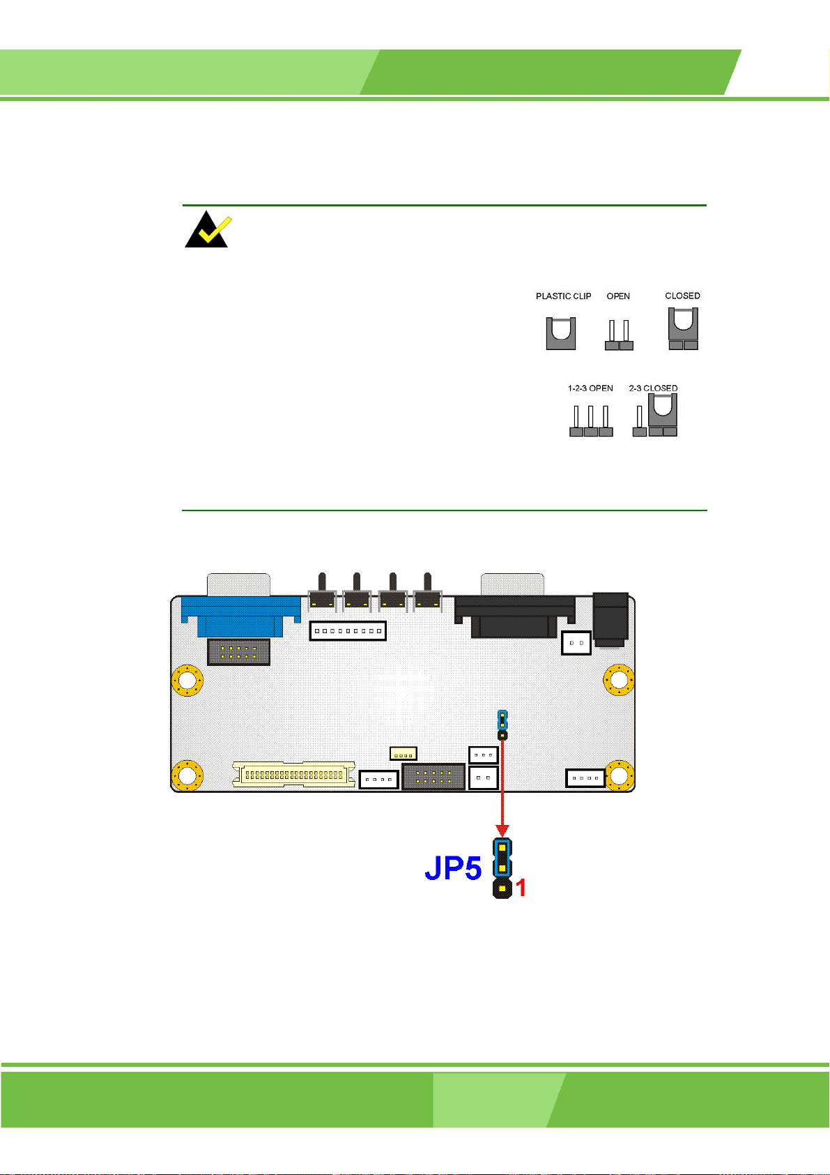
4.2.19 AV-9350 Onboard Jumper
NOTE:
A jumper is a metal bridge used to close an
electrical circuit. It consists of two or three metal
ins and a small metal clip (often protected by a
lastic cover) that slides over the pins to
connect them. To CLOSE/SHORT a jumper
means connecting the pins of the jumper with
the plastic clip and to OPEN a jumper means
removing the plastic clip from a jumper.
The AV-9350 has one onboard jumper (Table 4-3).
Figure 4-12: Jump er s
Figure 4-13: Jumper Location
Page 66
IEI® Technology, Corp.
Page 67

LCD KIT Series Monito
r
4.2.20 LCD Panel (TTL) Voltage Select Jumper
Jumper Label: JP5
Jumper Type: 3-pin header
Jumper Location:
Jumper Settings:
The JP5 jumper sets the voltage to the LCD panel.
JP5 Description
1-2 Panel Voltage select 5V
2-3 Panel Voltage select 3.3V (Default)
Table 4-17: LCD Panel (TTL) Voltage Select Jumper Settings
See Figure 4-13
See Table 4-17
Page 67
Page 68

4.3 AV-5350 AD Board
The following sections describe the AV-5350 AD board in detail.
4.3.1 AV-5350 AD Board Overview
Figure 4-14: AV-5350 AD Board Overview
4.3.2 AV-5350 AD Board Connectors
The AV-5350 AD board has the following connectors onboard:
1 x VGA connector
1 x External OSD and LED Indication connector
1 x LVDS connector
3 x 5V power connector
1 x Backlight Inverter connector
Page 68
IEI® Technology, Corp.
Page 69

LCD KIT Series Monito
r
The AV-5350 AD board has the following connectors on the board rear panel:
1 x VGA connector
1 x 12V DC power connector
The locations of the peripheral interface connectors for the AV-5350 AD board are shown
in Section 4.3.3. A complete list of all the peripheral interface connectors can be seen in
Section 0.
4.3.3 AV-5350 AD Board Layout
Figure 4-15 shows the onboard peripheral connectors and onboard jumpers.
Figure 4-15: Connector and Jumper Locations
Page 69
Page 70

4.3.4 AV-5350 Peripheral Interface Connectors
Table 4-18 shows a list of the peripheral interface connectors on the AV-5350 AD board.
Detailed descriptions of these connectors can be found in Section 0.
Connector Type Label
5V Power connector 2-pin header CN7, CN8, CN9
Backlight Inverter connector 6-pin header CN6
External OSD and
LED Indication connector
LVDS Output connector 30-pin header CN5
VGA connector 10-pin header J2
Table 4-18: AV-5350 Peripheral Interface Connectors
9-pin header CN2
4.3.5 AV-5350 Rear Panel Connectors
Table 4-19 lists the rear panel connectors and jumpers on the AV-5350 AD board.
Detailed descriptions of these connectors and jumpers can be found in Section 4.3.13.
Connector Type Label
DC 12V Power connector DC Power Jack J3
VGA Connector 15-pin VGA connector J1
Table 4-19: AV-5350 Rear Panel Connectors
4.3.6 AV-5350 Onboard Jumper
Table 4-20 lists the onboard jumper. A detailed description of the jumper can be found in
Section 4.3.16.
Jumper Type Label
LCD Panel Voltage Select 3-pin header JP1
Table 4-20: AV-5350 Onboard Jumper
Page 70
IEI® Technology, Corp.
Page 71

LCD KIT Series Monito
r
4.3.7 AV-5350 Internal Peripheral Connectors
Internal peripheral connectors on the AV-5350 AD board are only accessible when the
board is outside of the monitor. This section has complete descriptions of all the internal,
peripheral connectors on the AV-5350 AD board.
4.3.8 5V Power Connector
CN Label: CN7, CN8, CN9
CN Type: 2-pin header
CN Pinouts:
CN Location:
The 5V power connector is a general-purpose power connector.
Pin Description Pin Description
1 +5V 2 GND
Table 4-21: 5V Power Connector Pinouts
See T a b le 4 -21
See Figure 4-16
Figure 4-16: 5V Power Connector Location
Page 71
Page 72

4.3.9 Backlight Inverter Connector
CN Label: CN6
CN Type: 6-pin header
CN Pinouts:
CN Location:
The Inverter connector connects to the LCD backlight.
Pin Description
1 +12V
2 +12V
3 On/Off
4 BKLT_ADJ
5 GND
6 GND
Table 4-22: Backlight Inverter Connector Pinouts
See T a b le 4 -22
See Figure 4-17
Page 72
Figure 4-17: Backlight Inverter Connector Location
IEI® Technology, Corp.
Page 73

LCD KIT Series Monito
r
4.3.10 External OSD and LED Indication Connector
CN Label: CN2
CN Type: 9-pin header
CN Pinouts:
CN Location:
The External OSD and LED Indication connector connects to an external OSD controller.
Pin Description
1 LED_ORANGE
2 +5V
3 LED_GREEN
4 MENU/ENTER
5 RIGHT
6 LEFT
7 AUTO
8 LCD ON/OFF
9 GND
Table 4-23: External OSD and LED Indication Connector Pinouts
See T a b le 4 -23
See Figure 4-18
Figure 4-18: External OSD and LED Indication Connector Location
Page 73
Page 74

4.3.11 LVDS Output Connector
CN Label: CN7
CN Type: 30-pin header
CN Pinouts:
CN Location:
Use the LVDS output connector to connect the LCD panel to a system.
Pin Description Pin Description
1 GND 2 GND
3 TXO3+ 4 TXO3-
5 TXOC+ 6 TXOC-
7 TXO2+ 8 TXO2-
9 TXO1+ 10 TXO1-
11 TXO0+ 12 TXO0-
13 GND 14 GND
15 TXE3+ 16 TXE3-
17 TXEC+ 18 TXEC-
19 TXE2+ 20 TXE2-
See T a b le 4 -24
See Figure 4-19
Page 74
21 TXE1+ 22 TXE1-
23 TXE0+ 24 TXE0-
25 GND 26 GND
27 VDD 28 VDD
29 VDD 30 VDD
Table 4-24: LVDS Output Connector Pinouts
IEI® Technology, Corp.
Page 75

LCD KIT Series Monito
r
Figure 4-19: LVDS Output Connector Location
NOTE:
The supply voltage (3.3V (Default), 5V or 12V) can be selected via JP1.
4.3.12 VGA Connector
CN Label: J2
CN Type: 10-pin header
CN Pinouts:
CN Location:
See T a b le 4 -25
See Figure 4-20
In addition to the standard DB-15 female VGA connector (J1), a VGA connection can also
be made through the onboard CN2 10-pin header.
Page 75
Page 76

Pin Description Pin Description
1 RED 2 DDCCLK
3 GREEN 4 DDCDAT
5 BLUE 6 GROUND
7 HSYNC 8 GROUND
9 VSYNC 10 GROUND
Table 4-25: VGA Connector Pinouts
Figure 4-20: VGA Connector Location
4.3.13 AV-5350 External (Rear Panel) Connectors
Figure 4-21 shows the AV-5350 external (rear panel) connectors. The peripheral
connectors on the back panel of the monitor can connect to external devices. The
peripheral connectors on the rear panel are:
1 x DC 12V connector
1 x VGA connector
Page 76
IEI® Technology, Corp.
Page 77

r
Figure 4-21: AV-5350 External (Rear Panel) Connectors
4.3.14 DC 12V Connector
CN Label: J3
CN Type: DC 12V Jack
LCD KIT Series Monito
CN Pinouts:
CN Location:
Use the DC 12V connector to power the monitor.
PIN DESCRIPTION
1 GND
2 GND
3 DC 12V
Table 4-26: DC 12V Connector Pinouts
See T a b le 4 -26
See Figure 4-21
4.3.15 VGA Connector
CN Label: J1
CN Type: HD-D-sub 15 female connector
CN Pinouts:
CN Location:
Use the standard HD-D-sub 15-pin VGA connector to connect the monitor to a system.
See T a b le 4 -27 and Figure 4-22
Figure 4-21
Page 77
Page 78

A
p
p
PIN DESCRIPTION PIN DESCRIPTION
1 Red 9 No Connect
2 Green 10 Ground
3 Blue 11 No Connect
4 No Connect 12 DDC DAT
5 Ground 13 Horizontal Synchronization
6 Ground 14 Vertical Synchronization
7 Ground 15 DDC Clock
8 Ground
Table 4-27: VGA Connector Pinouts
Figure 4-22: VGA Connector Pinout Locations
4.3.16 AV-5350 Onboard Jumper
NOTE:
jumper is a metal bridge used to close an
electrical circuit. It consists of two or three metal
ins and a small metal clip (often protected by a
lastic cover) that slides over the pins to
connect them. To CLOSE/SHORT a jumper
means connecting the pins of the jumper with
the plastic clip and to OPEN a jumper means
removing the plastic clip from a jumper.
Figure 4-23: Jump er s
The AV-5350 has one onboard jumper (Table 4-20).
Page 78
IEI® Technology, Corp.
Page 79

LCD KIT Series Monito
r
Figure 4-24: Jumper Location
4.3.17 LCD Panel Voltage Select Jumper
Jumper Label: JP5
Jumper Type: 6-pin header
Jumper Location:
Jumper Settings:
The JP1 jumper sets the voltage to the LCD panel.
JP1 Description
1-2 Panel Voltage select 3.3V (Default)
See Figure 4-24
See Table 4-28
3-4 Panel Voltage select 5V
5-6 Panel Voltage select 12V
Table 4-28: LCD Panel Voltage Select Jumper Settings
Page 79
Page 80

4.4 AV-5300 AD Board
The following sections describe the AV-5300 AD board in detail.
4.4.1 AV-5300 AD Board Overview
Figure 4-25: AV-5300 AD Board Overview
Page 80
IEI® Technology, Corp.
Page 81

LCD KIT Series Monito
r
4.4.2 AV-5300 AD Board Connectors
The AV-5300 AD board has the following connectors onboard:
1 x VGA connector
1 x External OSD and LED Indication connector
2 x LVDS connector
3 x 5V power connector
1 x Backlight Inverter connector
1 x Debug connector
The AV-5300 AD board has the following connectors on the board rear panel:
1 x 12V DC power connector
1 x VGA connector
1 x DVI-D connector
The locations of the peripheral interface connectors for the AV-5300 AD board are shown
in Section 0. A complete list of all the peripheral interface connectors can be seen in
Section 4.4.4.
Page 81
Page 82

4.4.3 AV-5300 AD Board Layout
Figure 4-26 shows the onboard peripheral connectors and onboard jumpers.
Page 82
Figure 4-26: Connector and Jumper Locations
IEI® Technology, Corp.
Page 83

LCD KIT Series Monito
r
4.4.4 AV-5300 Peripheral Interface Connectors
Table 4-29 shows a list of the peripheral interface connectors on the AV-5300 AD board.
Detailed descriptions of these connectors can be found in Section 4.4.7.
Connector Type Label
5V Power connector 2-pin header CN2, CN9, CN15
Backlight Inverter connector 6-pin header CN6
DC/DC Power connector 3-pin connector CN10
Debugged Port connector 4-pin header CN4
External OSD and
LED Indication connector
LVDS Output connector 30-pin crimping connector CN7, CN17
VGA connector 10-pin header J1
Table 4-29: AV-5300 Peripheral Interface Connectors
9-pin header CN5
4.4.5 AV-5300 Rear Panel Connectors
Table 4-30 lists the rear panel connectors on the AV-5300 AD board. Detailed
descriptions of these connectors can be found in Section 4.4.15.
Connector Type Label
DC 12V Power connector DC Power Jack J4
VGA Connector 15-pin VGA connector J2
DVI-D Connector 24-pin DVI-D connector J3
Table 4-30: AV-5300 Rear Panel Connectors
Page 83
Page 84

4.4.6 AV-5300 Onboard Jumpers
Table 4-31 lists the onboard jumpers. A detailed description of these jumpers can be
found in Section 4.4.19.
Jumper Type Label
LCD Panel Power Input Select 6-pin header JP2
LCD Panel Voltage Select 6-pin header JP1
Table 4-31: AV-5300 Onboard Jumpers
4.4.7 AV-5300 Internal Peripheral Connectors
Internal peripheral connectors on the AV-5300 AD board are only accessible when the
board is outside of the monitor. This section has complete descriptions of all the internal,
peripheral connectors on the AV-5300 AD board.
4.4.8 5V Power Connector
CN Label: CN2, CN9, CN15
CN Type: 2-pin header
CN Pinouts:
CN Location:
The 5V power connector is a general-purpose power connector.
Pin Description Pin Description
1 +5V 2 GND
Table 4-32: 5V Power Connector Pinouts
See T a b le 4 -32
See Figure 4-27
Page 84
IEI® Technology, Corp.
Page 85

LCD KIT Series Monito
r
Figure 4-27: 5V Power Connector Location
Page 85
Page 86

4.4.9 Backlight Inverter Connector
CN Label: CN6
CN Type: 6-pin header
CN Pinouts:
CN Location:
The Inverter connector connects to the LCD backlight.
Pin Description
1 +12V
2 +12V
3 On/Off
4 BKLT_ADJ
5 GND
6 GND
Table 4-33: Backlight Inverter Connector Pinouts
See T a b le 4 -33
See Figure 4-28
Page 86
IEI® Technology, Corp.
Page 87

LCD KIT Series Monito
r
Figure 4-28: Backlight Inverter Connector Location
4.4.10 DC/DC Power Connector
CN Label: CN10
CN Type: 3-pin connector
Page 87
Page 88

CN Pinouts:
CN Location:
The DC/DC power connector connects the board to the optional 9~36V DC terminal block.
Pin Description
1 +5V
2 GND
3 +9V~+36V
Table 4-34: DC/DC Power Connector Pinouts
See T a b le 4 -34
See Figure 4-29
Page 88
IEI® Technology, Corp.
Page 89

LCD KIT Series Monito
r
Figure 4-29: DC/DC Power Connector Location
4.4.11 Debugged Port Connector
CN Label: CN4
CN Type: 4-pin header
CN Pinouts:
See T a b le 4 -35
Page 89
Page 90

CN Location:
Use the debugged port connector to update the AD board BIOS.
Pin Description
1 +5V
2 TX
3 RX
4 GND
Table 4-35: Debugged Port Connector Pinouts
See Figure 4-30
Page 90
IEI® Technology, Corp.
Page 91

LCD KIT Series Monito
r
Figure 4-30: Debugged Port Connector Location
4.4.12 External OSD and LED Indication Connector
CN Label: CN5
CN Type: 9-pin header
Page 91
Page 92

CN Pinouts:
CN Location:
The External OSD and LED Indication connector connects to an external OSD controller.
Pin Description
1 LED_ORANGE
2 +5V
3 LED_GREEN
4 MENU/ENTER
5 RIGHT
6 LEFT
See T a b le 4 -36
See Figure 4-31
7 AUTO
8 LCD ON/OFF
9 GND
Table 4-36: External OSD and LED Indication Connector Pinouts
Page 92
IEI® Technology, Corp.
Page 93

LCD KIT Series Monito
r
Figure 4-31: External OSD and LED Indication Connector Location
4.4.13 LVDS Output Connector
CN Label: CN7, CN17
CN Type: 30-pin crimped connector
Page 93
Page 94

CN Pinouts:
CN Location:
See T a b le 4 -37
See Figure 4-32
Use either LVDS output connector to connect the LCD panel to a system.
Pin Description Pin Description
1 GND 2 GND
3 TXO3+ 4 TXO3-
5 TXOC+ 6 TXOC-
7 TXO2+ 8 TXO2-
9 TXO1+ 10 TXO1-
11 TXO0+ 12 TXO0-
13 GND 14 GND
15 TXE3+ 16 TXE3-
17 TXEC+ 18 TXEC-
19 TXE2+ 20 TXE2-
21 TXE1+ 22 TXE1-
23 TXE0+ 24 TXE0-
25 GND 26 GND
27 VDD 28 VDD
29 VDD 30 VDD
Table 4-37: LVDS Output Connector Pinouts
Page 94
IEI® Technology, Corp.
Page 95

LCD KIT Series Monito
r
Figure 4-32: LVDS Output Connector Location
NOTE:
The supply voltage (3.3V (Default), 5V or 12V) can be selected via JP1.
4.4.14 VGA Connector
CN Label: J1
CN Type: 10-pin header
CN Pinouts:
CN Location:
See T a b le 4 -38
See Figure 4-33
Page 95
Page 96

In addition to the standard DB-15 female VGA connector (J1), a VGA connection can also
be made through the onboard CN2 10-pin header.
Pin Description Pin Description
1 RED 2 DDCCLK
3 GREEN 4 DDCDAT
5 BLUE 6 GROUND
7 HSYNC 8 GROUND
9 VSYNC 10 GROUND
Table 4-38: VGA Connector Pinouts
Page 96
IEI® Technology, Corp.
Page 97

LCD KIT Series Monito
r
Figure 4-33: VGA Connector Location
4.4.15 AV-5300 External (Rear Panel) Connectors
Figure 4-34 shows the AV-5300 external (rear panel) connectors. The peripheral
connectors on the back panel of the monitor can connect to external devices. The
peripheral connectors on the rear panel are:
1 x DC 12V connector
1 x VGA connector
1 x DVI-D connector
Page 97
Page 98

Figure 4-34: AV-5300 External (Rear Panel) Connectors
4.4.16 DC 12V Connector
CN Label: J3
CN Type: DC 12V Jack
CN Pinouts:
CN Location:
Use the DC 12V connector to power the monitor.
PIN DESCRIPTION
1 GND
2 GND
3 DC 12V
Table 4-39: DC 12V Connector Pinouts
See T a b le 4 -39
See Figure 4-34
Page 98
IEI® Technology, Corp.
Page 99
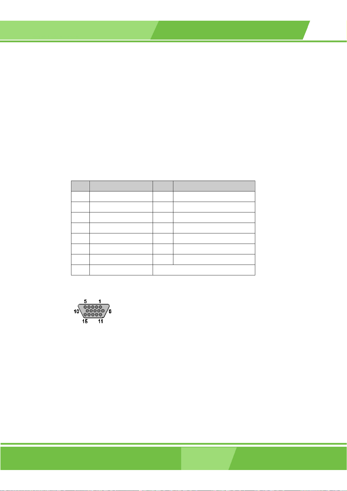
LCD KIT Series Monito
r
4.4.17 VGA Connector
CN Label: J2
CN Type: HD-D-sub 15 female connector
CN Pinouts:
CN Location:
Use the standard HD-D-sub 15-pin VGA connector to connect the monitor to a system.
PIN DESCRIPTION PIN DESCRIPTION
1 Red 9 No Connect
2 Green 10 Ground
3 Blue 11 No Connect
4 No Connect 12 DDC DAT
5 Ground 13 Horizontal Synchronization
6 Ground 14 Vertical Synchronization
7 Ground 15 DDC Clock
8 Ground
Table 4-40: VGA Connector Pinouts
See T a b le 4 -40 and Figure 4-35
See Figure 4-34
Figure 4-35: VGA Connector Pinout Locations
4.4.18 DVI-D Connector
CN Label: J3
CN Type: HD-D-sub 15 female connector
CN Pinouts:
See T a b le 4 -41 and Figure 4-36
Page 99
Page 100

CN Location:
See Figure 4-34
The 24-pin female dual link digital only DVI [Digital Visual Interface] connector is a
standard for high-speed, high-resolution digital displays. Use the DVI-D connector to
connect the LCD to a system.
PIN DESCRIPTION PIN DESCRIPTION PIN DESCRIPTION
1 TMDS Data2- 9 TMDS Data1- 17 TMDS Data02 TMDS Data2+ 10 TMDS Data1+ 18 TMDSData0+
3 TMDS Data2/4 Shield 11 TMDS Data1/3 Shield 19 TMDS Data0/5 Shield
4 TMDS Data4- 12 TMDS Data3- 20 TMDS Data55 TMDS Data4+ 13 TMDS Data3+ 21 TMDS Data5+
6 DDC Clock [SCL] 14 +5 V Power 22 TMDS Clock Shield
7 DDC Data [SDA] 15 Ground (for +5 V) 23 TMDS Clock +
8 Analog vertical sync 16 Hot Plug Detect 24 TMDS Clock -
Table 4-41: DVI-D Connector Pinouts
Figure 4-36: DVI-D Connector Pinout Locations
Page 100
IEI® Technology, Corp.
 Loading...