

Page 1

IMK-571R Software and Programming Guides
IEI Technology Corp.
IMK-571R Software and
Programming Guides
IMK Runtime DEMO User Guide,
XML Merchandise Manager User Guide,
and MSR Programming Guide
User Manual
Rev. 1.00 – 29 September, 2009
Page i
Page 2
Date Version Changes
29 September, 2009 1.00 Initial release
IMK-571R Software and Programming Guides
Revision
Page ii
Page 3
IMK-571R Software and Programming Guides
COPYRIGHT NOTICE
The information in this document is subject to change without prior notice in order to
improve reliability, design and function and does not represent a commitment on the part
of the manufacturer.
In no event will the manufacturer be liable for direct, indirect, special, incidental, or
consequential damages arising out of the use or inability to use the product or
documentation, even if advised of the possibility of such damages.
This document contains proprietary information protected by copyright. All rights are
Copyright
reserved. No part of this manual may be re produced by any mechanical, electronic, or
other means in any form without prior written permission of the manufacturer.
TRADEMARKS
All registered trademarks and product names mentioned herein are used for identification
purposes only and may be trademarks and/or registered trademarks of their respective
owners.
Page iii
Page 4
IMK-571R Software and Programming Guides
Table of Contents
1 WINDOWS CE SETUP ................................................................................................ 1
START UP AND SHUT DOWN ........................................................................................ 2
1.1
1.1.1 Start up......................................................... ..... ... ..... ... ..... ..... ... ..... ... ..... ...... .. ....2
1.1.2 Shut down....................................................... ... ..... ... ..... ...... .. ...... ..... ... ..... ... ..... .3
1.2
LIST OF FUNCTIONS....................................................................................................4
1.2.1 List of Window CE applications and services................................................... .4
1.2.2 List of Control Panel............................................ ............................................. .6
1.3
CONTROL PANEL SETTINGS........................................................................................ 7
1.3.1 Stylus.................................................... .. ...... .. ...... ..... ... ..... ... ..... ..... ... ..... ...... .. ....9
1.3.2 Network..................................................... ..... ... ..... ... ..... ...... .. ...... .. ...... ..... ... ....10
1.3.3 Volume & Sounds ............................................................................................. 12
1.3.4 Keyboard........................................................ ... ..... ... ..... ...... .. ...... ..... ... ..... ... ....13
1.3.5 System .................................. ..... ... ..... ..... ... ..... ...... .. ...... .. ...... ..... ... ..... ... ..... ..... ..13
1.4
BUILT-IN USER APPLICATIONS OF WINDOWS CE 5.0................................................ 15
1.4.1 Internet Explor er.................................................................................. .. .......... 16
1.4.2 Set up a Remote Desktop Connection.................................................... .......... 18
1.4.3 Software-based Input Panel............................................................................. 21
1.4.4 Media Player................................................................................ .................... 22
1.4.5 File Viewer................................................................... .................................... 23
1.4.6 Setup System Time..................................... ..... ...... .. ...... .. ...... ..... ... ..... ... ..... ..... ..24
1.5
IEI CEUTILITY 1.0 ................................................................................................ 25
1.5.1 Launching IEI CEUTILITY 1.0........................................................................ 25
1.5.2 General Settings................................................ ... ..... ..... ... ..... ... ..... ...... .. ...... .. ..25
1.5.2.1 Registry Settings..................... .............................................. .. .................. 26
1.5.2.2 Save Registry Settings..............................................................................26
1.5.3 Auto Execution.......................................................... ........ ........... ........ .......... ..27
1.6
CONTENTS OF DEFAULT SECURE DIGITAL CARD MEMORY CARD.............................. 29
1.6.1 OS Image, Logo File and Configuration File................................... ............... 29
1.6.2 List of applications in system folder................................. ... ............................ 29
1.6.2.1 Screen Capture.......................................................................................... 30
Page iv
Page 5
IMK-571R Software and Programming Guides
1.6.2.2 IEI_RMTCE & CEVncSvr....................................................................... 30
1.6.2.3 IEI_CEUTILITY....................................................................................... 30
1.6.2.4 RegEdit ................................. ............................................. ....................... 30
1.6.2.5 REGSVR32 & REGSVRCE.............................................. ....................... 31
1.6.2.6 Save Registry............................................................................................ 32
CONFIGURATION FILE............................................................................................... 32
1.7
1.7.1 Overview...................................... ..... ..... ... ..... ... ..... ...... .. ...... ..... ... ..... ... ..... ..... ..32
1.7.2 Offset 0x00: Load Registry From EEPROM.................................................... 33
1.7.3 Offset 0x01: Erase Registry in EEPR OM........................................................33
1.7.4 Offset 0x02: Display T y pe................................................................................33
2 USING THE REMOTE MANAGEMENT TOOL................................................... 34
2.1 ABOUT IEI REMOTE MANAGEMENT TOOLS ............................................................. 35
2.1.1 Overview...................................... ..... ..... ... ..... ... ..... ...... .. ...... ..... ... ..... ... ..... ..... ..35
2.1.2 Important Features of the IEI Remote Management Tools.............................. 35
2.1.3 System Requireme n t.......................................................... ... ..... ..... ... ..... ... ..... ..35
2.1.4 Concept..................................... ... ..... ..... ... ..... ...... .. ...... .. ...... ..... ... ..... ... ..... ..... ..35
TO INSTALL IEI REMOTE MANAGEMENT TOOLS ...................................................... 36
2.2
REMOTE MANAGEMENT TOOLS ............................................................................... 38
2.3
WAKE UP/ CONFIGURE/ UPDATE/ CONNECT AN IEI WINDOWS CE DEVICE............... 40
2.4
2.4.1 Connect Remote Device.................................... ... ..... ..... ...... .. ...... ..... ... ..... ..... ..41
2.4.2 Configure an IEI Windows CE device....................... .......................................41
2.4.2.1 General............................... ............................................. .......................... 42
2.4.2.2 Control Panel ............................. ............................................. .................. 42
2.4.2.3 Define Terminal Connection of an IEI Windows CE Device................... 45
2.4.2.4 Remote Desktop Display...................................... .................................... 47
2.4.2.5 Configure FTP Settings of an IEI Windows CE device............................ 48
2.4.2.6 Update an IEI Windows CE device ................................................... ....... 49
2.4.2.7 Record Logs for WBT............................................. .................................. 51
2.4.2.8 Wake on Lan ...................................................... ... .錯誤! 尚未定義書籤。
2.4.2.9 Network Parameter Configuration..................................................... ... .... 52
2.4.2.10 Account management.......................................... ............................. ....... 53
3 IMK RUNTIME DEMO............................................................................................. 55
3.1
DEMO PATH .............................................................................................................. 56
Page v
Page 6
3.2
MAIN PAGE .............................................................................................................. 56
VIDEO PLAYER ......................................................................................................... 57
3.3
BUTTON F1: BARCODE DEMO.................................................................................. 58
3.4
BUTTON F2: PRINTER DEMO....................................................................................60
3.5
BUTTON F3: MSR DEMO. ........................................................................................ 62
3.6
BUTTON F4: EXIT..................................................................................................... 63
3.7
IMK-571R Software and Programming Guides
4 XML MERCHANDISE MANAGER.................................................. ..... ...... .. ...... ....64
4.1 STARTING THE XML MERCHANDISE MANAGER....................................................... 65
4.2
MODIFYING THE XML FILE...................................................................................... 65
SCANNING FOR XML FILES ON THE NETWORK SUBNET........................................... 72
4.3
DOWNLOADING XML FILES FROM IMK-571R ........................................................74
4.4
UPLOADING XML FILES TO IMK-571R................................................................... 77
4.5
5 IMK WEB INTERFACE............................................................................................. 80
5.1 IMK WEB INTERFACE MAIN PAGE........................................................................... 81
5.2
SYSTEM SETTINGS PAGES.........................................................................................82
5.2.1 Main Page...................................... ... ............................................. .................. 82
5.2.2 Device Information........................................ ...... ..... ... ..... ... ..... ... ..... ..... ... ..... ..83
5.2.3 Ethernet............................................................................................................ 84
5.2.4 W ireless.................................. ........... ........ ........... ........ .......... ........ ........... .......85
5.2.5 Restart Network..................................................................................... ... ....... 86
5.2.6 Reboot System.................................................................................................. 87
5.3
BARCODE SETTINGS PAGES...................................................................................... 88
5.3.1 Main Frame ................................... .............................................. .................... 88
5.3.2 Support Codetypes ........................................................................................... 89
5.3.3 Beeper Option................................................................ .................................. 90
5.3.4 T ri gger Mode.......... ........... ........ ........... .......... ........ ........... ........ ........... .......... ..91
5.3.5 Factory Default...................................... ... ....................................................... 92
5.3.6 Version Information........ ........ ........... ........... ........ .......... ........... ........ ........... ....93
6 GENERAL SOFTWARE DEVELOPMENT............................................................94
APPLICATION DEVELOPMENT ENVIRONMENT........................................................... 95
6.1
6.1.1 Hardw are Environment........................................................ ..... ... ..... ... ..... ..... ..95
6.1.2 Softwar e Environment............................................................ ... ..... ...... .. ...... ....96
6.2
INSTALLING APPLICATION DEVELOPMENT TOOLS .................................................... 96
Page vi
Page 7
IMK-571R Software and Programming Guides
6.2.1 Installing the IEI ALCHEMY Windows CE 5.0 SDK....................................... 97
6.3
INSTALLING ACTIVESYNC ...................................................................................... 102
6.3.1 Establishing a Connection via ActiveSync..................................................... 102
6.3.2 Connection Procedure Using a Serial Cable.................................................102
6.4
APPLICATION DEVELOPMENT..................................................................................111
6.4.1 Development using eMbedded Visual C++ 4.0..............................................111
6.4.1.1 Creating a Project.....................................................................................112
6.4.1.2 Configuration of the Platform Manager...................................................116
6.4.1.3 Program Debugged Using IMK-570....................................................... 120
6.4.1.4 Programs Released for IMK-570............................................................ 120
6.4.1.5 Program Debugged Using the Emulator................................................. 121
6.4.2 Development Using Visual Studio .NET 2003................................................ 121
6.4.2.1 Creating a Project............................... ............................................. ........ 122
6.4.2.2 Building and Downloading a Program ...................................................124
6.4.2.3 Program Debugged Using the Emulator................................................. 126
6.4.2.4 Program Debugged Using IMK-570....................................................... 126
7 CONTROL BARCODE SCANNER WITH BARCONTROL.OCX .................... 129
7.1
METHOD SUMMARY............................................................................................... 130
ADD BARCONTROL.OCX OBJECT IN HTML.......................................................... 130
7.2
READBARCODE(INT ILOWTRIGTIME).................................................................... 130
7.3
8 MSR PROGRAMMING GUIDE FOR IMK-571R-CE5/MSR.............................131
8.1 ADDING KEYBOARD SUPPORT................................................................................132
8.1.1 *.h........................... ...... .. ...... ..... ... ..... ... ..... ..... ... ..... ...... .. ...... .. ...... ..... ... ..... ... ..132
8.1.2 *.cpp............................................................. .. ...... ..... ... ..... ... ..... ..... ... ..... ...... ..132
9 FAQ ............................................................................................................................. 134
WHY DID THE SYSTEM HANG AT END OF PROGRESS BAR DURING BOOTING? ........... 135
9.1
HOW TO SETUP SYSTEM CONFIGURE WHEN CHANGE DISPLAY? ............................... 135
9.2
A TERMI NOLOGY.................... ........ .......... ........... ........... ........ .......... ........... ........... ..140
Page vii
Page 8
IMK-571R Software and Programming Guides
List of Figures
Figure 1–1: Windows Splash Screen............................................................................................2
Figure 1–2: Desktop .......................................................................................................................3
Figure 1–3: Control Panel..............................................................................................................8
Figure 1–4: Save Registry..............................................................................................................8
Figure 1–5: Touch Screen Calibration..........................................................................................9
Figure 1–6: Control Panel..............................................................................................................9
Figure 1–7: Touch Screen Calibration........................................................................................10
Figure 1–8: IP Address Selection................................................................................................10
Figure 1–9: Name Server Selection ..................................................... .... ... ........ .... ... .... .... .... .... .11
Figure 1–10: Network Not Ready ................................................................................................11
Figure 1–11: Network Ready .......................................................................................................11
Figure 1–12: Network Icons........................................................................................................ .11
Figure 1–13: Renew Network Status...........................................................................................12
Figure 1–14: DHCP Warning........................................................................................................12
Figure 1–15: Volume & Sounds Properties................................................................................13
Figure 1–16: Keyboard Properties..............................................................................................13
Figure 1–17: Control Panel..........................................................................................................14
Figure 1–18: System Properties..................................................................................................14
Figure 1–19: Memory Properties.................................................................................................14
Figure 1–20: Device Name...........................................................................................................15
Figure 1–21: Copyrights ..............................................................................................................15
Figure 1–22: Desktop ...................................................................................................................16
Figure 1–23: Internet Explorer Icon............................................. ...............................................16
Figure 1–24: Website URL ...........................................................................................................16
Figure 1–25: Internet Explorer File Menu...................................................................................17
Figure 1–26: Internet Explorer Edit Menu ..................................................................................17
Figure 1–27: Internet Explorer View Menu.................................................................................17
Figure 1–28: Internet Explorer Favorites Menu.........................................................................18
Figure 1–29: Remote Desktop Icon.............................................................................................18
Figure 1–30: Remote Desktop Simple Interface........................................................................18
Page viii
Page 9
IMK-571R Software and Programming Guides
Figure 1–31: Remote Desktop Extended Interface....................................................................19
Figure 1–32: Remote Desktop Programs Tab............................................................................20
Figure 1–33: Remote Desktop General Tab.................................... ...........................................20
Figure 1–34: Remote Desktop Connection................................................................................21
Figure 1–35: Windows Server 2003 Logon ................................................................................21
Figure 1–36: Software Keyboard Icon......................................... ...............................................22
Figure 1–37: Large Software Keyboard................................................................................. .....22
Figure 1–38: Normal Software Keyboard...................................................................................22
Figure 1–39: Media Player Desktop Icon....................................................................................22
Figure 1–40: Windows Media Player...........................................................................................23
Figure 1–41: Microsoft® Excel Desktop Icon ............................................................................23
Figure 1–42: Microsoft® WordPad Desktop Icon......................................................................24
Figure 1–43: Microsoft® PowerPoint Viewer Desktop Icon .....................................................24
Figure 1–44: Microsoft®® Image Viewer Desktop Icon............................................................24
Figure 1–45: Microsoft® PDF Viewer Desktop Icon..................................................................24
Figure 1–46: System Time ...........................................................................................................24
Figure 1–47: Date/Time Properties .............................................................................................25
Figure 1–48: IEI CE Utility............................................................................................................26
Figure 1–49: Save Registry..........................................................................................................27
Figure 1–50: Auto Execution.......................................................................................................28
Figure 1–51: Auto Execution Choose Program Dialog.............................................................28
Figure 1–52: OS Image, Startup Logo and Configuration File.................................................29
Figure 1–53: IEI_RMTCE Log File ......................................... ......................................................29
Figure 1–54: System Directory....................................................................................................29
Figure 1–55: Screen Capture Icon ..............................................................................................30
Figure 1–56: Screen Capture.......................................................................................................30
Figure 1–57: Registry Editor........................................................................................................31
Figure 1–58: Save Registry..........................................................................................................32
Figure 2–1: Remote Management Tools Overview ........................................... ........................36
Figure 2–2: Remote Management Setup Installation Options .................................................37
Figure 2–3: Remote Management Setup Installation Folder....................................................37
Figure 2–4: Remote Management Setup Completed ................................................................38
Figure 2–5: Remote Management...............................................................................................38
Figure 2–6: Remote Management...............................................................................................39
Figure 2–7: Remote Management Set Subnet ...........................................................................39
Page ix
Page 10
Figure 2–8: Remote Management Set Subnet ...........................................................................40
Figure 2–9: Remote Management Device Search .....................................................................40
Figure 2–10: Remote Management.............................................................錯誤! 尚未定義書籤。
Figure 2–11: Security check Dialog............................................................錯誤! 尚未定義書籤。
Figure 2–12: Remote Management Enable device toolbar.......................錯誤! 尚未定義書籤。
Figure 2–13: Search for Devices.................................................................................................41
Figure 2–14: Device List ......................................................................................................... .....41
Figure 2–15: Terminal Properties................................................................................................42
Figure 2–16: Terminal Properties General Tab..........................................................................42
Figure 2–17: Terminal Properties Display Tab ..........................................錯誤! 尚未定義書籤。
Figure 2–18: Terminal Properties Control Panel Tab................................................................43
Figure 2–19: Set Device Time......................................................................................................43
Figure 2–20: System Property General Tab...............................................................................44
Figure 2–21: System Property Device Name Tab......................................................................44
Figure 2–22: System Property Copyright Tab ...........................................................................45
IMK-571R Software and Programming Guides
Figure 2–23: RDP Connection Properties..................................................................................45
Figure 2–24: Terminal Connection Manager..............................................................................46
Figure 2–25: Connection Startup................................................................................................46
Figure 2–26: VNC Connection Properties....................................... ...........................................47
Figure 2–27: Client PC VNC Viewer............................................................................................48
Figure 2–28: FTP Connection Settings.......................................................................................48
Figure 2–29: Set FTP Directory.................................................... ...............................................49
Figure 2–30: Device Update.........................................................................................................49
Figure 2–31: Device Update Dialog.............................................................................................50
Figure 2–32: Browse for System Image .....................................................................................50
Figure 2–33: System Logs...........................................................................................................51
Figure 2–34: Log Download Dialog.............................................................................................52
Figure 2–35: Power of Ethernet...................................................................錯誤! 尚未定義書籤。
Figure 2–36:Wake-On-Lan Dialog...............................................................錯誤! 尚未定義書籤。
Figure 2–37: Network parameter configuration.........................................................................52
Figure 2–38:Net Config Dialog ....................................................................................................53
Figure 2–39: Account management............................................................................................54
Figure 2–40:Security check Dialog.............................................................錯誤! 尚未定義書籤。
Figure 2–41:Account Setting Dialog -> change Admin password...........................................54
Page x
Page 11
IMK-571R Software and Programming Guides
Figure 2–42: Account Setting Dialog -> Add User、Modify User、Delete User錯誤! 尚未定義
書籤。
Figure 2–43:Add New User Dialog Æ Add User ........................................錯誤! 尚未定義書籤。
Figure 2–44: Add New User Dialog Æ Modify User...................................錯誤! 尚未定義書籤。
Figure 3–1: Main Screen ............................................................................... ... .... .... ....... .... .........56
Figure 3–2: Play Video ................................................................................. ........ .... .... ... .... .........57
Figure 3–3: Barcode Demo............................................ .... .... ... .... .... .... ........ ... .... .... .... ... .... .........58
Figure 3–4: Barcode Demo - Test Mode..................................................................... ................59
Figure 3–5: Main Screen ............................................................................... ... .... .... ....... .... .........60
Figure 3–6: Main Screen ............................................................................... ... .... .... ....... .... .........61
Figure 3–7: MSR Demo Screen ...................................................................................................6 2
Figure 3–8: Exit.............................................................................................................................63
Figure 4–1: XML Merchandise Manager Icon ............................................................................65
Figure 4–2: Main Window ................................................................. ........ ... .... .... .... .... ... .... .........65
Figure 4–3: XML List Dialog ........................................................................................................67
Figure 4–4: XML File Product List...............................................................................................67
Figure 4–5: Save Local XML Product File..................................................................................68
Figure 4–6: Edit Product Information.........................................................................................68
Figure 4–7: Update Product Information................................................. ... ........ .... ... .... .... .... .....69
Figure 4–8: Add New Product .....................................................................................................70
Figure 4–9: Add New Product Dialog .........................................................................................70
Figure 4–10: Delete Product from XML File...............................................................................71
Figure 4–11: Scan Subnet............................................................................................................72
Figure 4–12: Web Interface......................................................................................................... .73
Figure 5–1: Main Screen ............................................................................... ... .... .... ....... .... .........81
Figure 5–2: Main System Settings Page..................................................................... ... .... .... .... .82
Figure 5–3: Device Information (System Settings Page)..........................................................83
Figure 5–4: Ethernet (System Settings Page)............................................................................84
Figure 5–5: Wireless (System Settings Page) ...........................................................................85
Figure 5–6: Restart Network (System Settings Page)...............................................................86
Figure 5–7: Reboot System (System Settings Page)............................................... .... .... ........ .87
Figure 5–8: Main Barcode Settings Page......................... .... ....... .... .... .... ... .... ........ .... ... .... .... .....88
Figure 5–9: Supported Codetypes (Barcode Settings Page) ...................................................89
Figure 5–10: Beeper Option (Barcode Setting Page)............................................... .................90
Figure 5–11: Trigger Mode (Barcode Settings Page)................................................................91
Page xi
Page 12
Figure 5–12: Factory Default (Barcode Settings Page) ........................................ ....................92
Figure 5–13: Version Information (Barcode Settings Page) ....................................................93
Figure 6–1: SDK Installation File.................................................................................................97
Figure 6–2: SDK Installation Welcome Screen..........................................................................98
Figure 6–3: SDK License Agreement..........................................................................................98
Figure 6–4: SDK Customer Information ............................................................. .... .... ... .... .... .....99
Figure 6–5: SDK Setup Type Selection ......................................................................................99
Figure 6–6: SDK Custom Setup Options................................................................................. 100
Figure 6–7: SDK Destination Folder Selection....................................................................... 100
Figure 6–8: SDK Ready to Install............................................................................................. 101
Figure 6–9: SDK Installation Progress Bar............................................................................. 101
Figure 6–10: SDK Installation Complete ........................................................................... ...... 102
Figure 6–11: Network and Dial-up Connections..................................................................... 103
Figure 6–12: Make New Connection........................................................................................ 103
Figure 6–13: Make Direct Connection ..................................................................................... 104
IMK-571R Software and Programming Guides
Figure 6–14: Select Device Connection .................................................................................. 104
Figure 6–15: Port Settings........................................................................................................ 105
Figure 6–16: PC Connection..................................................................................................... 105
Figure 6–17: Change Connection to My Connection............................................................. 105
Figure 6–18: Save Registry....................................................................................................... 106
Figure 6–19: Connect With ActiveSync................................................................................... 106
Figure 6–20: Connect Device ............................................ ....................................................... 107
Figure 6–21: Searching for Device........................................................................................... 108
Figure 6–22: Set Up a Partnership........................................................................................... 109
Figure 6–23: Synchronization Settings................................................................................... 109
Figure 6–24: Device Setup Complete ...................................................................................... 110
Figure 6–25: Device Connected with ActiveSync .................................................................. 110
Figure 6–26: Stop Synchronization ......................................................................................... 111
Figure 6–27: Creating a New Project....................................................................................... 112
Figure 6–28: Select the VCE Emulator .................................................................................... 113
Figure 6–29: Select Single Document ..................................................................................... 113
Figure 6–30: Select Required Functions................................................................................. 114
Figure 6–31: Select Source File Options................................................................................. 114
Figure 6–32: Finish Setup......................................................................................................... 115
Figure 6–33: New Project Information..................................................................................... 116
Page xii
Page 13
IMK-571R Software and Programming Guides
Figure 6–34: Platform Manager Configuration ....................................................................... 117
Figure 6–35: Platform Manager Configuration ....................................................................... 118
Figure 6–36: Platform Manager Device Properties ................................................................ 118
Figure 6–37: Platform Manager Example Program...................................................... .......... 119
Figure 6–38: Connect With ActiveSync................................................................................... 120
Figure 6–39: Connect With ActiveSync................................................................................... 120
Figure 6–40: My Device Desktop Icon..................................................................................... 120
Figure 6–41: Run Test Program....................................................... ........................................ 121
Figure 6–42: Emulator Debugging........................................................................................... 121
Figure 6–43: Create New Project.............................................................................................. 122
Figure 6–44: Smart Device Application Wizard...................................................................... 123
Figure 6–45: New Project Page................................................................................................ 124
Figure 6–46: Dialog Properties................................................................................................. 125
Figure 6–47: Debugging............................................................................................................ 125
Figure 6–48: Select Target Device........................................................................................... 126
Figure 6–49: Select Deployment Device ................................................................................. 127
Figure 6–50: Select Windows CE .NET Device....................................................................... 127
Figure 6–51: Example Program Output................................................................................... 128
Figure 9–1: Setup File ............................................................................................................... 135
Page xiii
Page 14
IMK-571R Software and Programming Guides
List of Tables
Table 6–1: Hardware Requirements................................................. ...........................................96
Table 6–2: Software Requirements.............................................................................................96
Page xiv
Page 15
IMK-571R Software and Programming Guides
1 Windows CE Setup
Chapter
1
Page 1
Page 16
IMK-571R Software and Programming Guides
1.1 Start up and Shut down
1.1.1 Start up
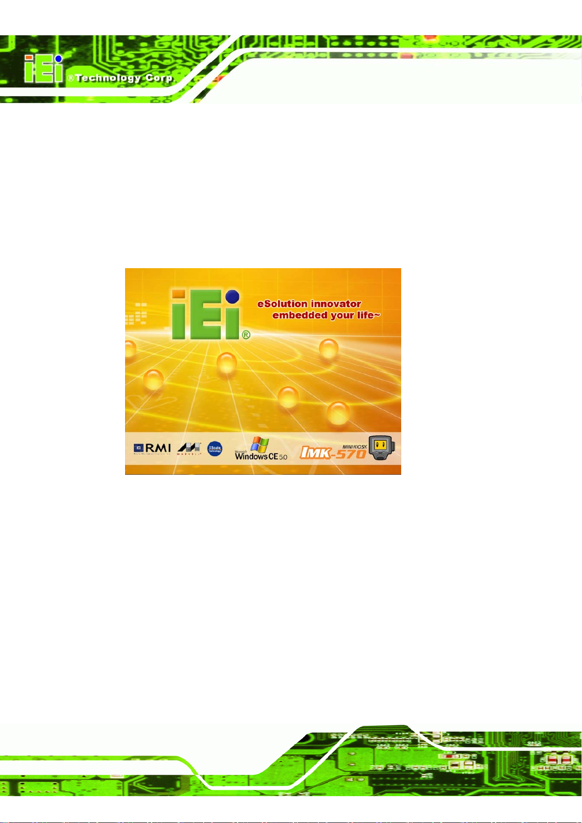
Windows CE starts automatically when the system is turned on.
The initial screen shows for 30 seconds while loading Windows C E 5.0. Th e sta rtup image
can be changed by overwriting the default "logo.bmp" with a customized one. Ideal
resolution is 640 x 480 pixels, with 65536 colors in bitmap format.
Page 2
Figure 1–1: Windows Splash Screen
Page 17
IMK-571R Software and Programming Guides
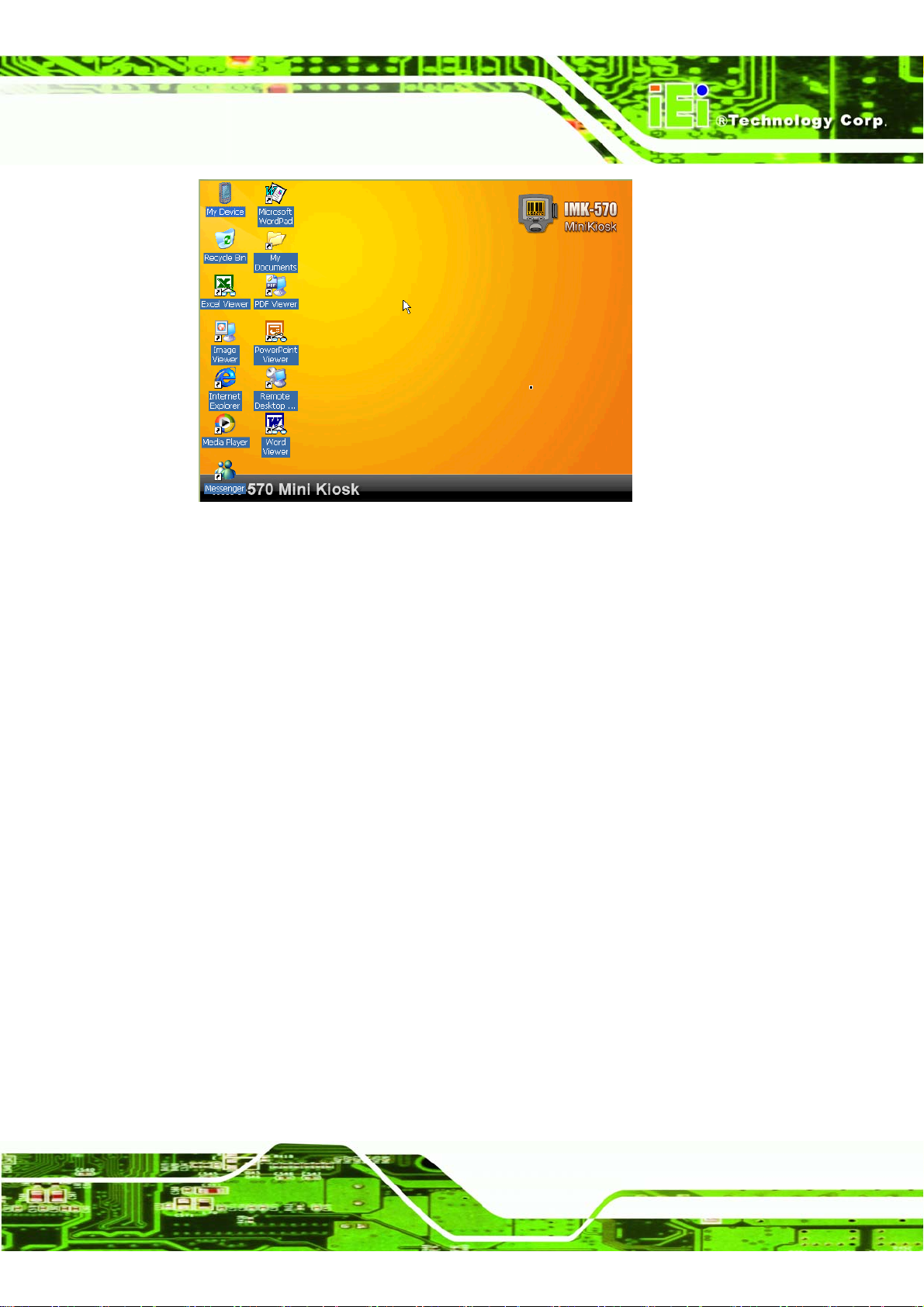
Figure 1–2: Desktop
If the progress bar stalls and the system does not boot, please check in the following
order.
Step 1: Check SD card is installed correctly
Step 2: Check SD card is formatted with FAT16
Step 3: Check SD card contents are formatted correctly
Step 4: The OS image NK.bin should be on the SD card and not be crashed
Step 5: If the OS image is crashed, prepare a new SD card with the same contents
Step 6: Contact technical support Step 0:
1.1.2 Shut down
The SD card will be damaged if it is removed, or the system is turned off while the card is
being accessed. To shutdown just turn off the device when the SD card is not being
accessed.
NOTE: Always save your work before turning off the system.
Page 3
Page 18
IMK-571R Software and Programming Guides
1.2 List of Functions
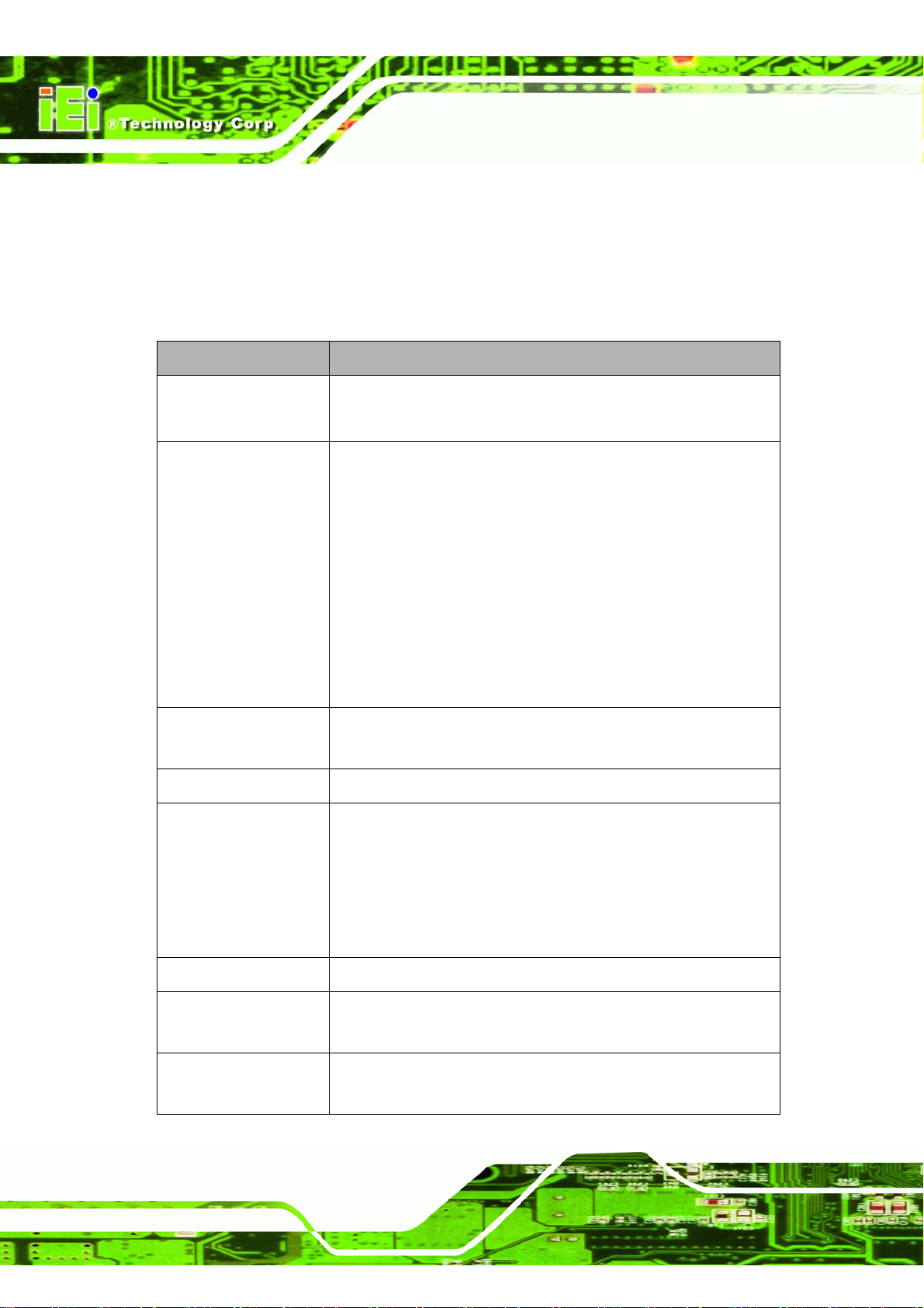
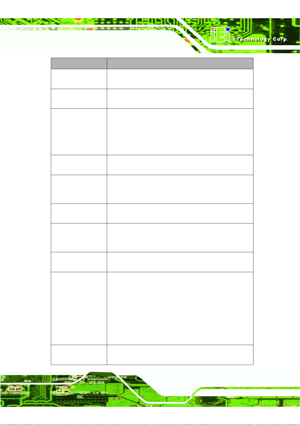
1.2.1 List of Window CE applications and services
There are a range of programs that can be in cluded on a Windows CE installation. The
fewer programs that are included, the faster Windows will run.
Services Descriptions
RDP client Remote desktop connection client program. Corresponds to a
password preservation function and auto logon.
Internet Explorer Web browser
Menu bar, status bar and button bar can be removed for true
full-screen display.
Can be set as the exclusive interface for Web browser-o nly
machines.
When installed, Internet option is added, and screen functions
can be toggled.
<Cash Location>
RAM Drive
SIP (Software- based
Input Panel)
Media Player Windows Media Player
File Viewers Microsoft® Excel Spreadsheet View e r
WordPad text editor Simple word processor
ActiveSync Synchronizes data between a desktop and Windows CE device.
The larger size onscreen keyboa rd. It is accessibl e using the icon
in the system tray.
Microsoft® Word Document Viewer
Microsoft® PowerPoint Presentation Viewer
Microsoft® Imag e Viewer
Microsoft® PDF V i ewer
This device supports ActiveSync 3.5 and up.
MFC (Microsoft®
Foundation Classes)
Page 4
A fram ework for building applications, COM component s and
controls.
Page 19
IMK-571R Software and Programming Guides
Services Descriptions
Active Template Library
(A TL)
C Libraries and
Run-times
Component Services
(COM and DCOM)
Standard Win32 SDK
for Windows CE
WinSock 2.0 Winsock handles input/output requests for Internet applications in
Windows Networking
API
A C++ template library for creating small, fast Microsoft®
ActiveX® servers.
All C libraries and run-times for Windows CE
An operating system-independent, object-oriented system for
creating binary software components that interact with other
COM-based components in the same process space, in other
processes, or on remote machines. Three levels of run-time
support are available.
Software Development Kit with common baseline Windows CE
technologies for easily porting applications
Windows. Winsock runs between an application program such as
a browser and the Internet program that uses TCP/IP.
Manages network connections and accesses remote file systems
and printers.
TCP/IP Offers network sharing resources including IP, ARP, ICMP, IGMP,
TCP and UDP. Also supports DHCP and includes helper APIs for
easy access.
XML services and
support
File system and dat a
store registry settings
NET Compact
Framework
Supports Microsoft XML version 3.0 Service Pack 1
The file system and data store are called the object store. The
object store consists of a file system, database, and system
registry that share a single memory heap. It provides persistent
storage for applications and their data even when the main power
supply is lost. The object store can be up to 256 MB of
compressible, nonvolatile, RAM storage. It integrates the
read-only files that are stored in ROM with the read/write files of
both an application and a user.
A runtime environment for easier program development
Page 5
Page 20
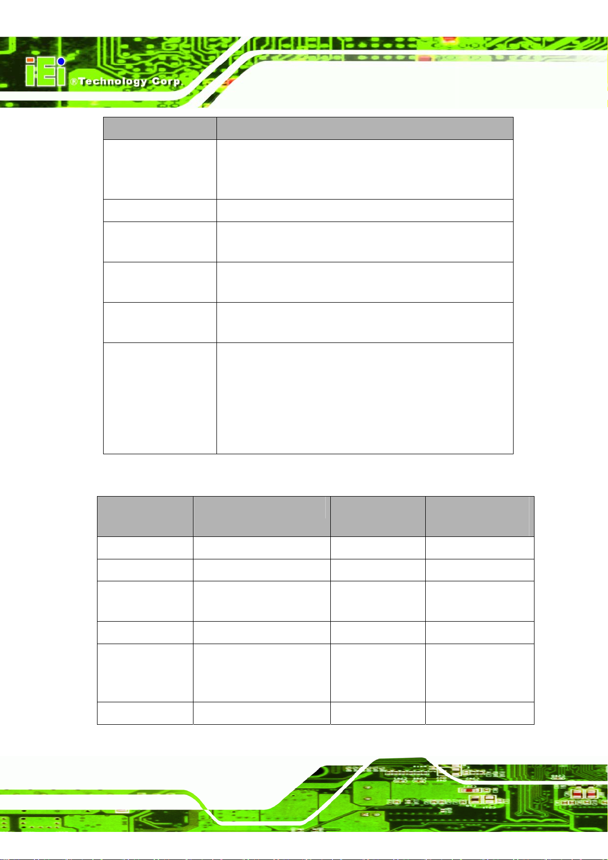
Services Descriptions
IMK-571R Software and Programming Guides
WBT (Windows based
Terminal)
FTP Server Allows the device to become an FTP server
HTTP Server Allows remote systems to monitor, configure or control the
Telnet Server After installation, this device can administered remotely using a
VNC Server Allows another computer to "see" the devices screen on their
DOS prompt and Shell The shell provides the user with an interface to the objects
Available on RDP client's terminal. Acts in the same manner as
password preservation and auto-logon.
* Explorer shell cannot be used with this
system through HTTP on a web browser.
telnet client
desktop and use their mou s e an d k ey board to control it
necessary for running applications and managing the Microsoft®
Windows® CE operating sys t em on a target device. These can
be real objects on the target device, such as files and folders;
virtual objects, such as the Recycle Bin; or remote objects
accessed through a network.
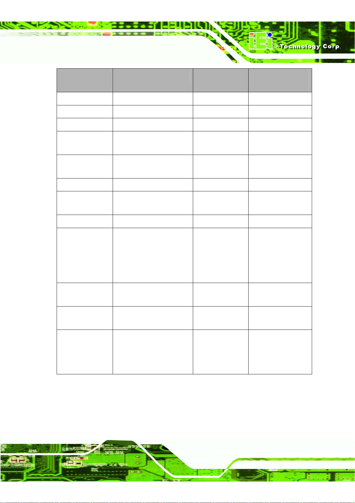
1.2.2 List of Control Panel
Icons Details Save Registry
after execution
Certificates Set up certificates Required Required
Date/Time Set the date and time Required Required
Device
Management
Dialing Set up dials Required Required
Display Set up panel display
Input Panel Setting input panel Not Required Required
Page 6
Set Device Management Required Required
Required Not Required
*Set up other items related
to display such as wallpaper
Power reset after
execution
Page 21
IMK-571R Software and Programming Guides
Icons Details Save Registry
after execution
Internet Option Set Internet options Required Required
Keyboard Set up keyboard Required Required
Mouse Set up mouse Required Required
Network and
Dial-up Connection
Owner Set up the owner’s
Password Set up or change password Not Required Required
PC Connection Set up connecting
Regional Settings Select the regional settings Required Required
Remove Programs Delete installed applications.
Set up network environment Not Required Required
Required Required
information
Required Required
computers
Not Required Required
* Need to save its registry
Power reset after
execution
except Digital’s program.
* Required to restart when
uninstalling.
Stylus Set up touch panel.
* Set up calibration here.
System Set up allocation of a
memory and device name.
Volume & Sounds Control volume and sound.
* Should set up touch
sounds or click sounds in
here.
1.3 Control Panel Settings
All the device settings are changed through the control panel.
Step 1: Click on Start.
Required Not Required
Required Not Required
Required Not Required
Page 7
Page 22
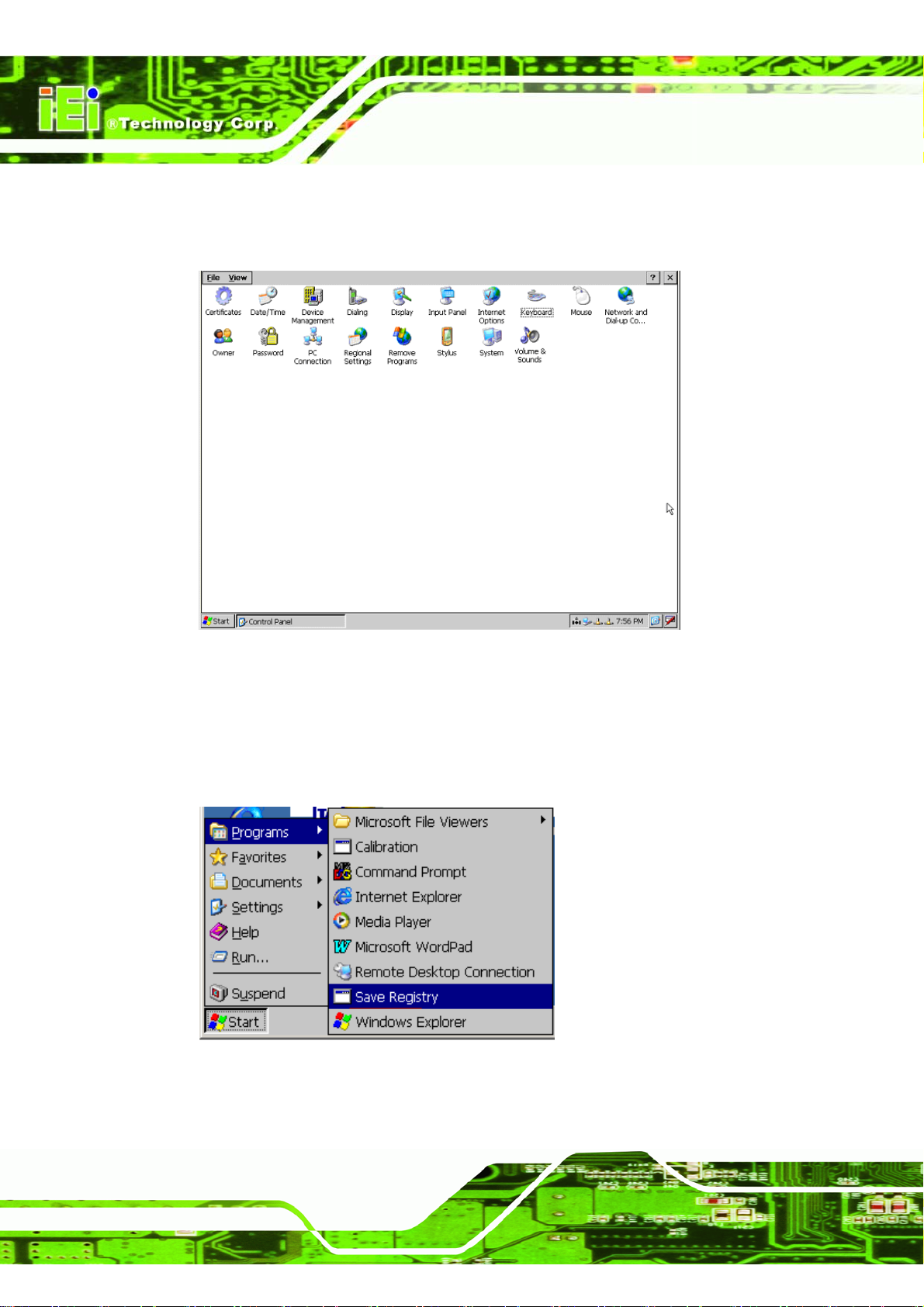
Step 2: From the Start menu, select Settings.
Step 3: Then select Control Panel.
IMK-571R Software and Programming Guides
Figure 1–3: Control Panel
Step 4: Make any required changes.
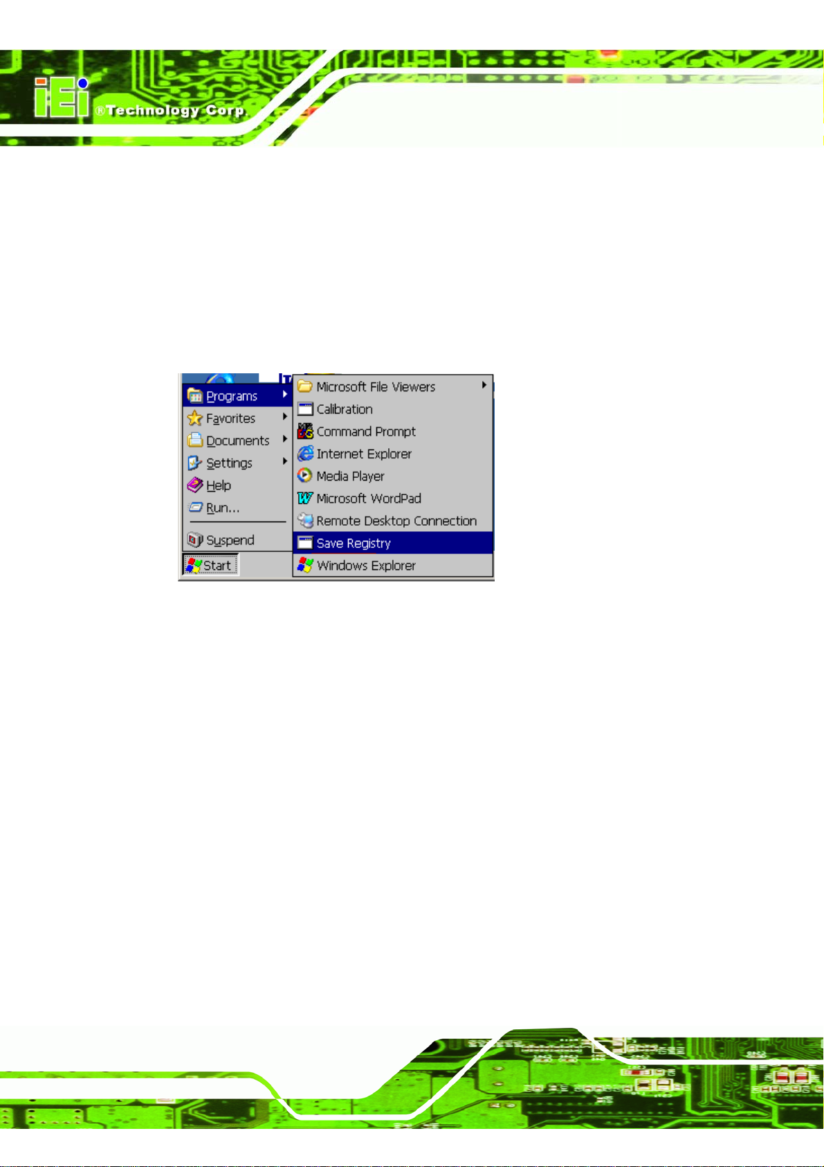
Step 5: Select "Start->Programs->Save Registry" to save any changes. If not saved to
the registry, the changes will revert back after a system restart. Step 0:
Figure 1–4: Save Registry
Page 8
Page 23
IMK-571R Software and Programming Guides
1.3.1 Stylus
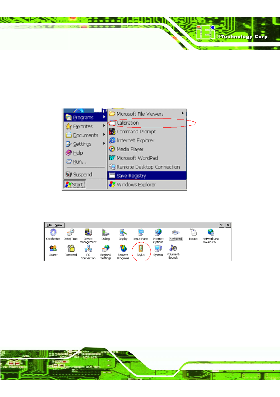
Calibrate the touch screen to ensure that input using the stylus is correct.
Step 1: Double click the Stylus icon on the Control Panel or [Start] -> [Programs] ->
[Calibration]
Figure 1–5: Touch Screen Calibration
Step 2: Select the Stylus tab.
Figure 1–6: Control Panel
Step 3: Click Recalibrate.
Step 4: Click on and hold the + mark at the center of the screen. When the coordinates
are recognized, the + mark will move in order from the center to the top left,
bottom left, bottom right, and top right. Click on and hold the + mark at each
point. Step 0:
Page 9
Page 24
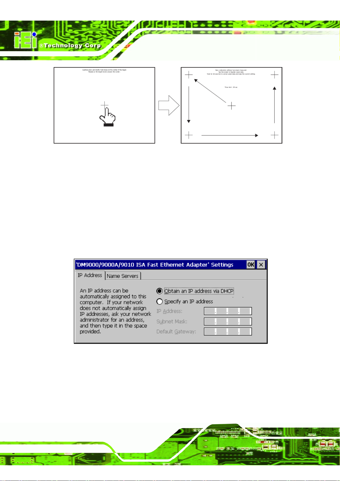
Figure 1–7: Touch Screen Calibration
1.3.2 Network
To connect to a wired network throu gh the Et hern e t ca bl e, do the fol l ow in g.
Step 1: Double click the Network and Dial-up Connections icon on the Control Panel.
IMK-571R Software and Programming Guides
Step 2: Double click the DM9CE1 icon.
Step 3: Set the IP address and Name Server in accordance with your netw ork
environment (ask your network administrator for details).
Figure 1–8: IP Address Selection
Page 10
Page 25
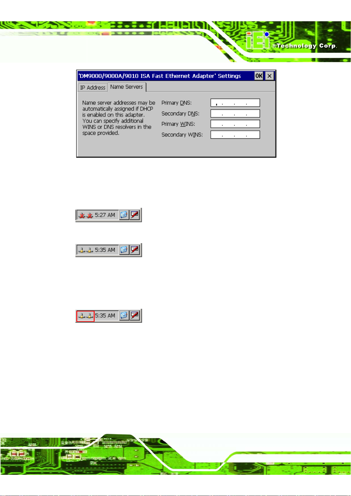
IMK-571R Software and Programming Guides
Figure 1–9: Name Server Selection
Step 4: Before running Internet Explorer, make sure the network cables are attached
and verify the network is connected.
Figure 1–10: Network Not Ready
Figure 1–11: Network Ready
Step 5: If the network does not become ready, double-click the icon of the
non-connected network.
Figure 1–12: Network Icons
Step 6: Click the renew button to try to refresh the network status.
Page 11
Page 26
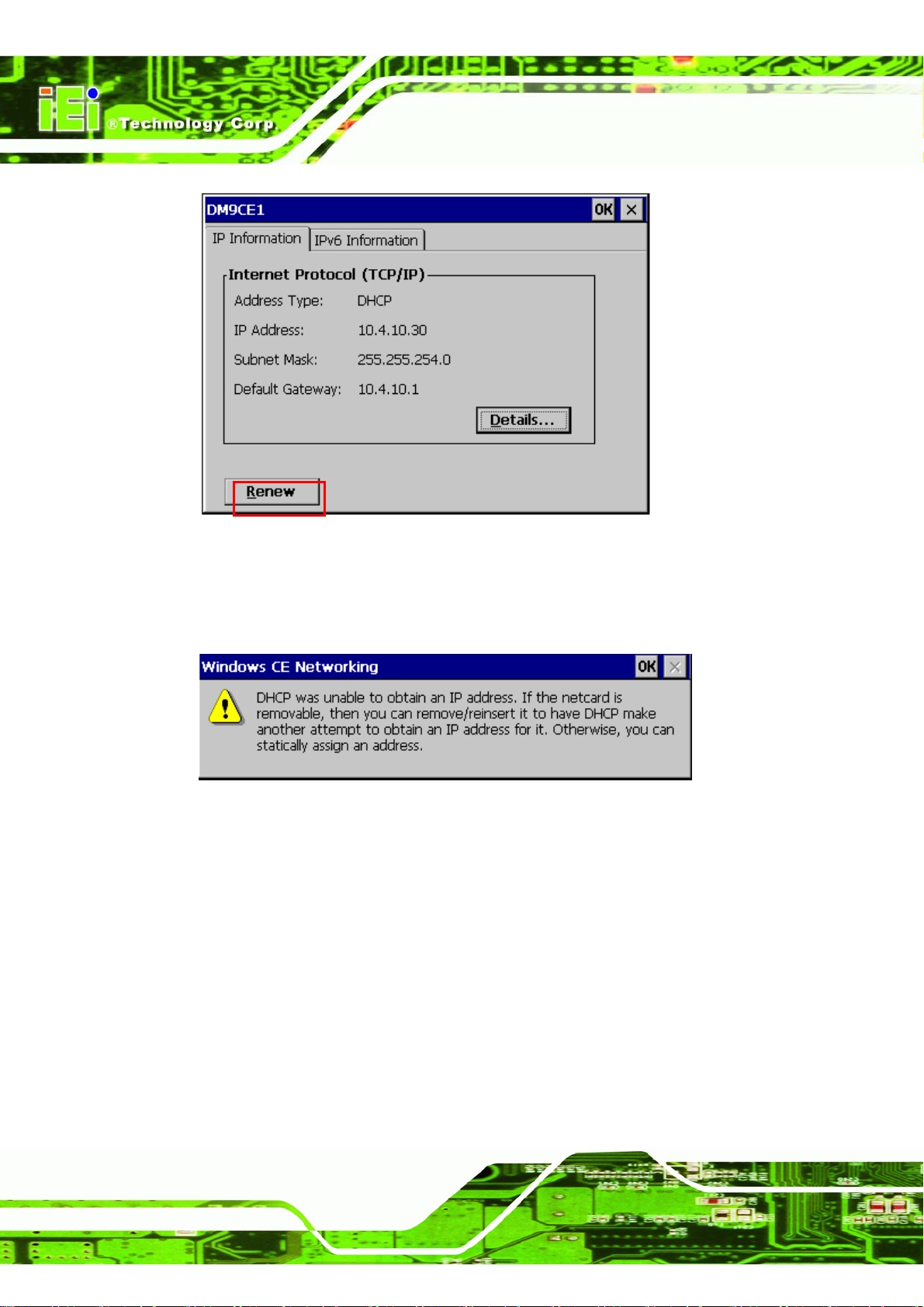
Figure 1–13: Renew Network Status
IMK-571R Software and Programming Guides
Step 7: If the system is unable to connect to a network, the following message is
displayed. Click OK to close the message window.
Figure 1–14: DHCP Warning
Step 8: If the original IP has not been used for a while, it might not work any more. If all
other settings are correct then the old IP needs to be removed from the registry.
Clicking "Save Regis try" saves these settings and should make connection
quicker the next time. Step 0:
1.3.3 Volume & Sounds
Change the volume and the system sounds.
Page 12
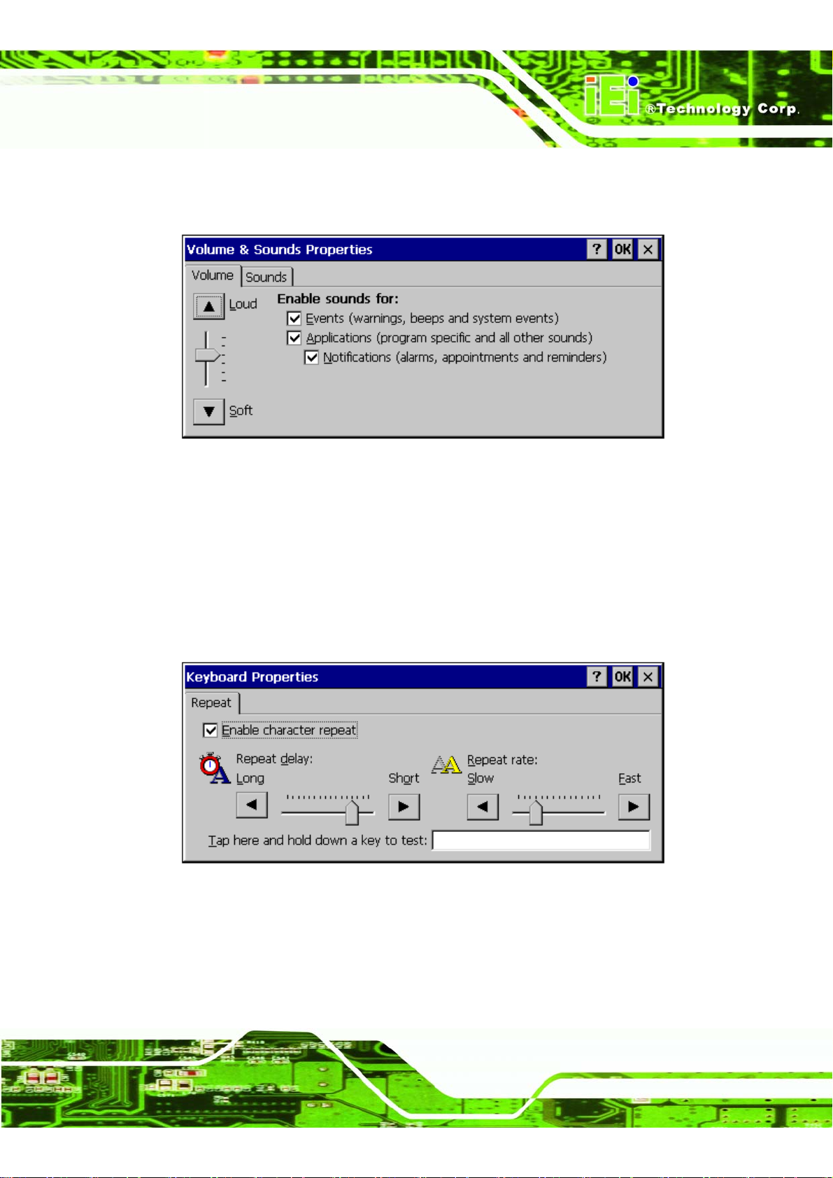
Step 1: Double click the Volume & Sounds icon on the Control Panel.
Page 27
IMK-571R Software and Programming Guides
Step 2: Click the Volume tab. next, set the [Enable sounds for:] to either ON or OFF.
Step 0:
Figure 1–15: Volume & Sounds Properties
1.3.4 Keyboard
Set the properties of the keyboard.
Step 1: Double click the Keyboard icon on the Control Panel.
Step 2: Select the Repeat tab.Step 0:
Figure 1–16: Keyboard Properties
1.3.5 System
Change the system settings.
Page 13
Page 28
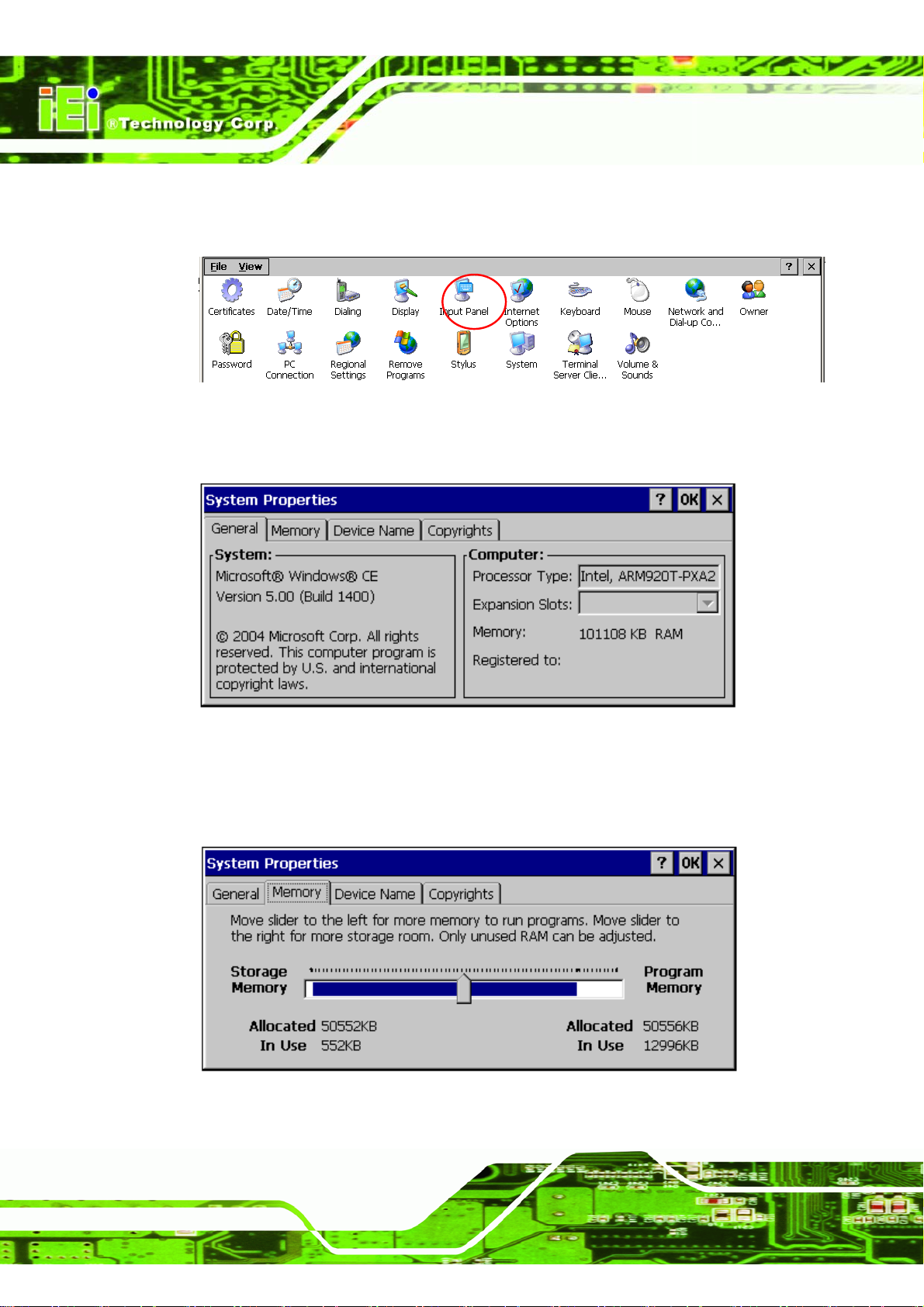
Step 1: Double click the System icon on the Control Panel or [Start] -> [Programs] ->
[System]]
Figure 1–17: Control Panel
Step 2: General: shows the system information.
IMK-571R Software and Programming Guides
Figure 1–18: System Properties
Step 3: Memory: move the slider to the left for more memory to run programs. Move
slider to the right for more storage. Only unused RAM can be adjusted.
Figure 1–19: Memory Properties
Page 14
Page 29
IMK-571R Software and Programming Guides
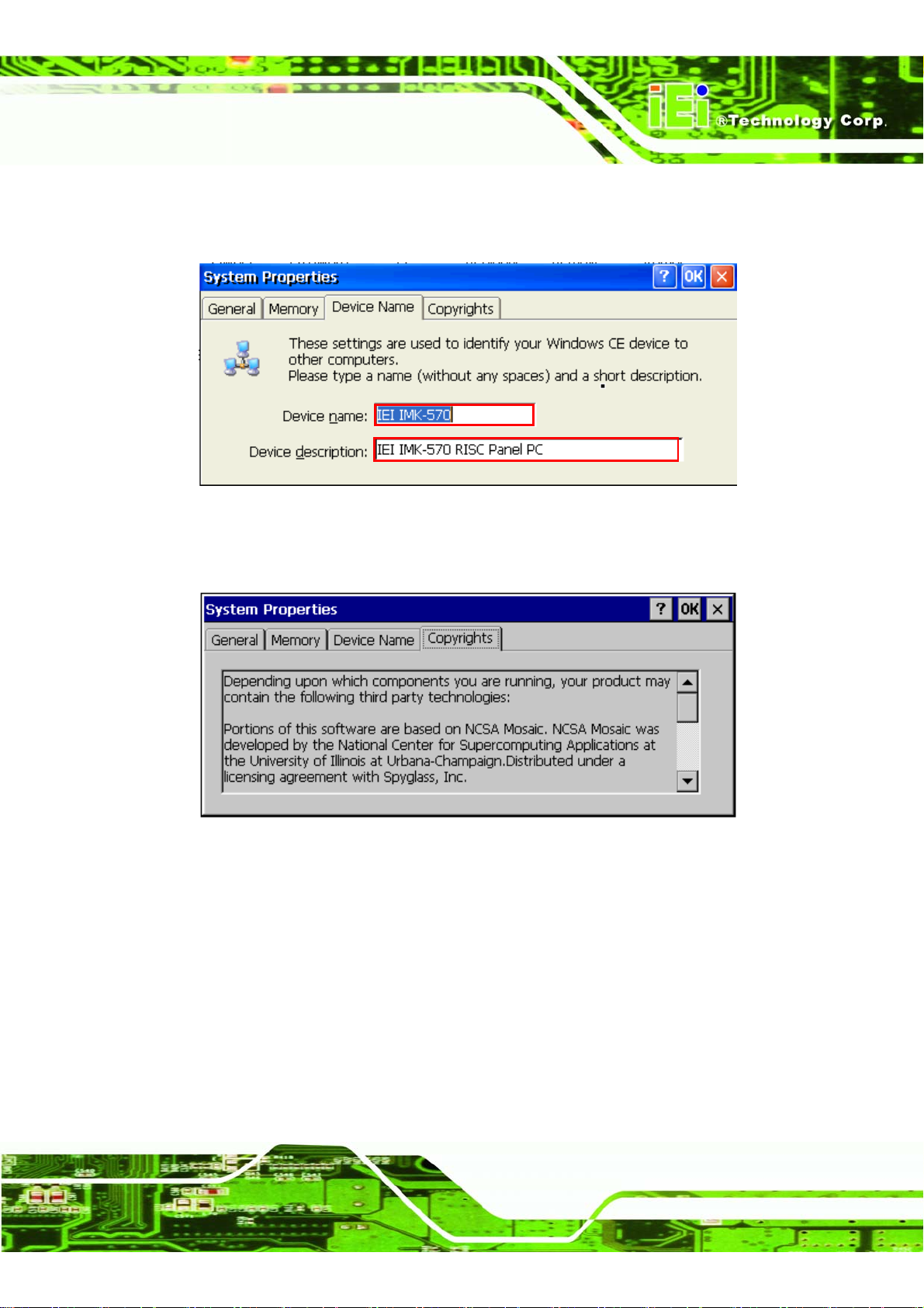
Step 4: Device Name: These setting are used to identify your Windows CE device to
other computers. Please type a name and a short description.
Figure 1–20: Device Name
Step 5: Copyrights: displays the copyrights for the operating system.Step 0:
Figure 1–21: Copyrights
1.4 Built-in User Applications of Windows CE 5.0
The built-in applications are shown on the desktop or in the start menu.
Page 15
Page 30
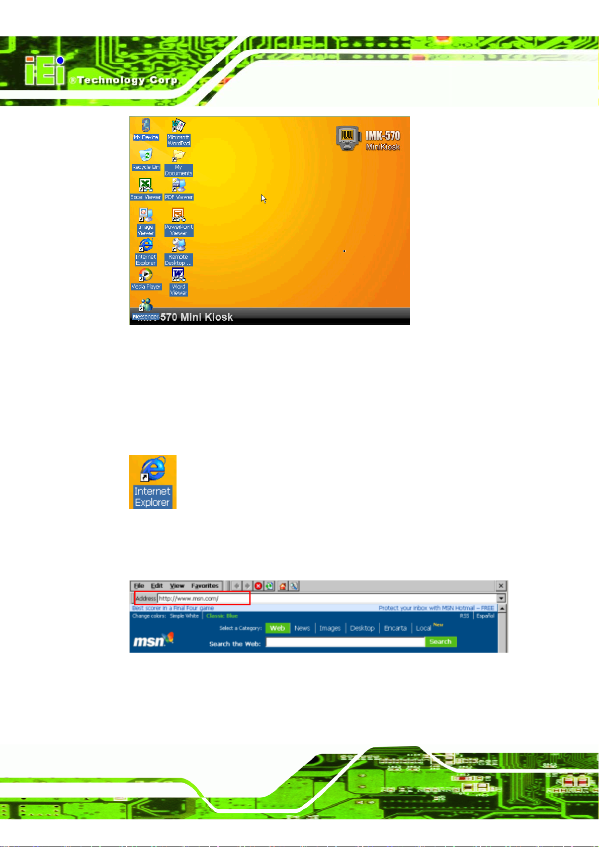
Figure 1–22: Desktop
1.4.1 Internet Explorer
IMK-571R Software and Programming Guides
How to use Internet Explorer.
Step 1: Open Internet Explorer.
Figure 1–23: Internet Explorer Icon
Step 2: Enter the website address (URL).
Figure 1–24: Website URL
Page 16
Common functions on the toolbar.
Page 31
IMK-571R Software and Programming Guides
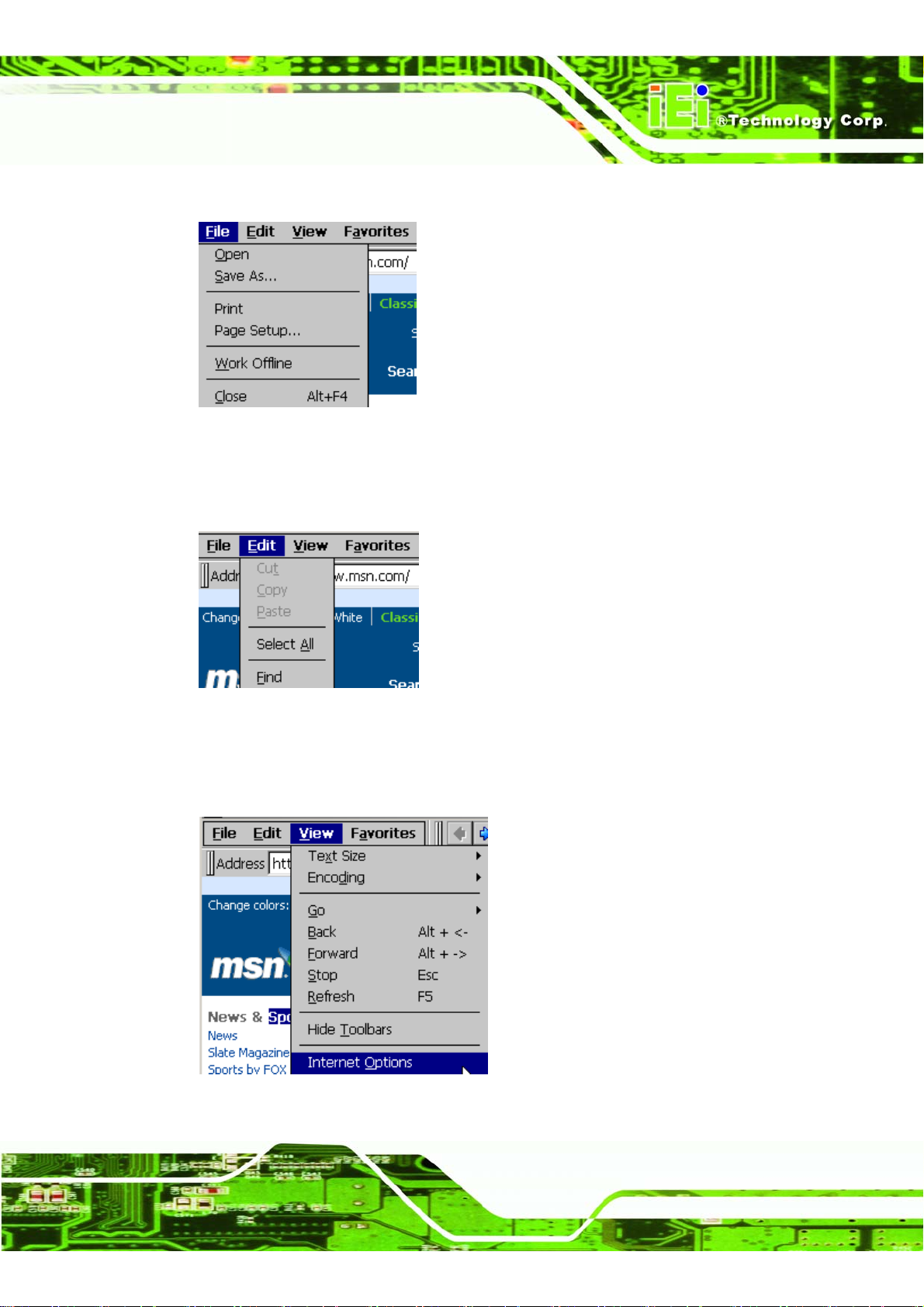
Step 3: File: [Open], [Save As…], [Print], [Page Setup…], [Work Offline] functions.
Figure 1–25: Internet Explorer File Menu
Step 4: Edit: [Cut], [Copy], [Paste], [Select All], [Find] functions to edit the context of the
current page.
Figure 1–26: Internet Explorer Edit Menu
Step 5: View: sets the view of the current page. There are further settings in Internet
Options.
Figure 1–27: Internet Explorer View Menu
Page 17
Page 32
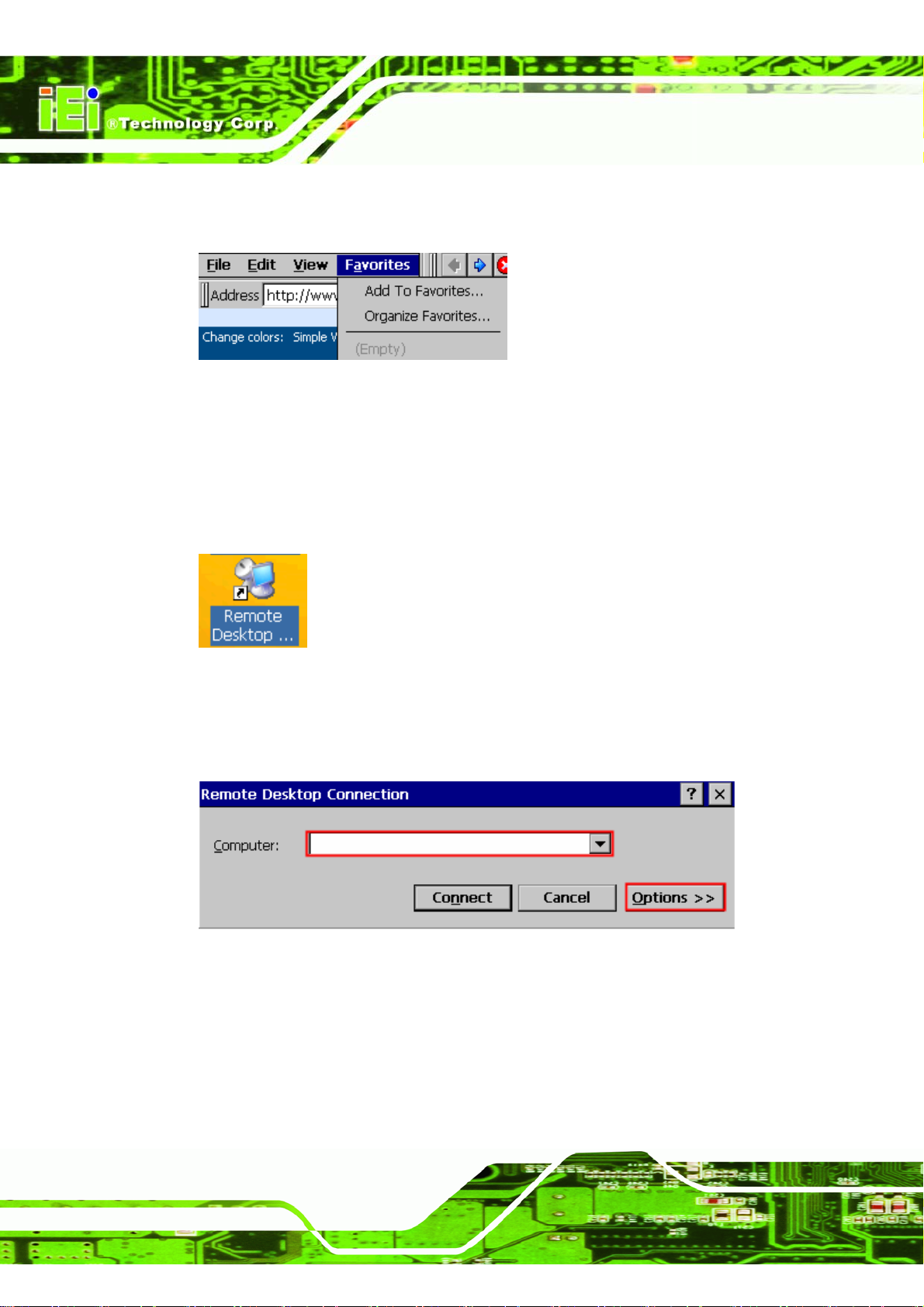
Step 6: Favorites: keeps track of favorite sites and allows them to be retrieved easily.
Step 0:
Figure 1–28: Internet Explorer Favorites Menu
IMK-571R Software and Programming Guides
1.4.2 Set up a Remote Desktop Connection
Set up a connection to a host computer.
Step 1: Double-click the Remote Desktop icon on the desktop.
Figure 1–29: Remote Desktop Icon
Step 2: To create a connection for Thin Client, please enter the Computer name and
click Options.
Figure 1–30: Remote Desktop Simple Interface
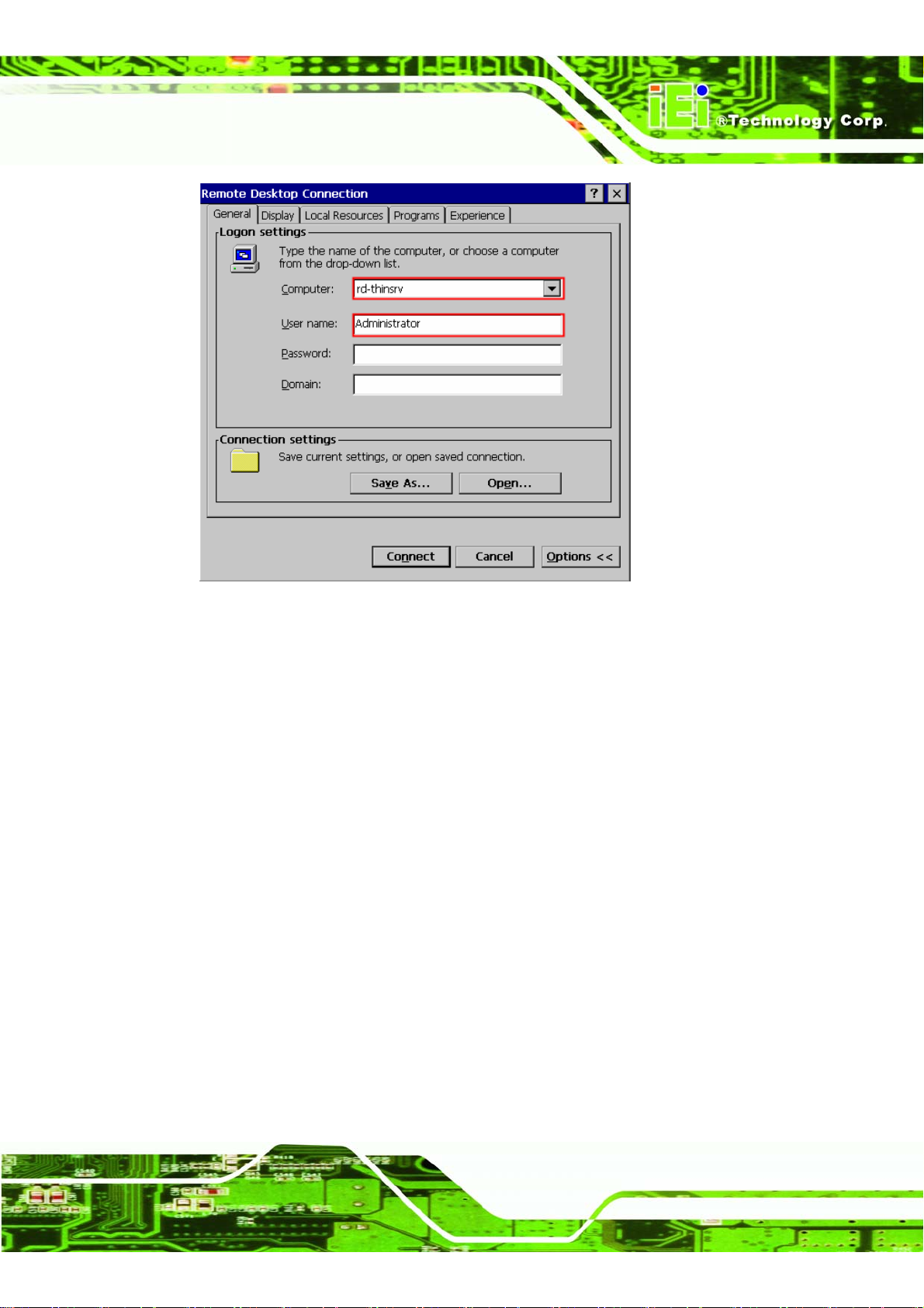
Step 3: Enter the user name and password to connect to the computer.
Page 18
Page 33
IMK-571R Software and Programming Guides
Figure 1–31: Remote Desktop Extended Interface
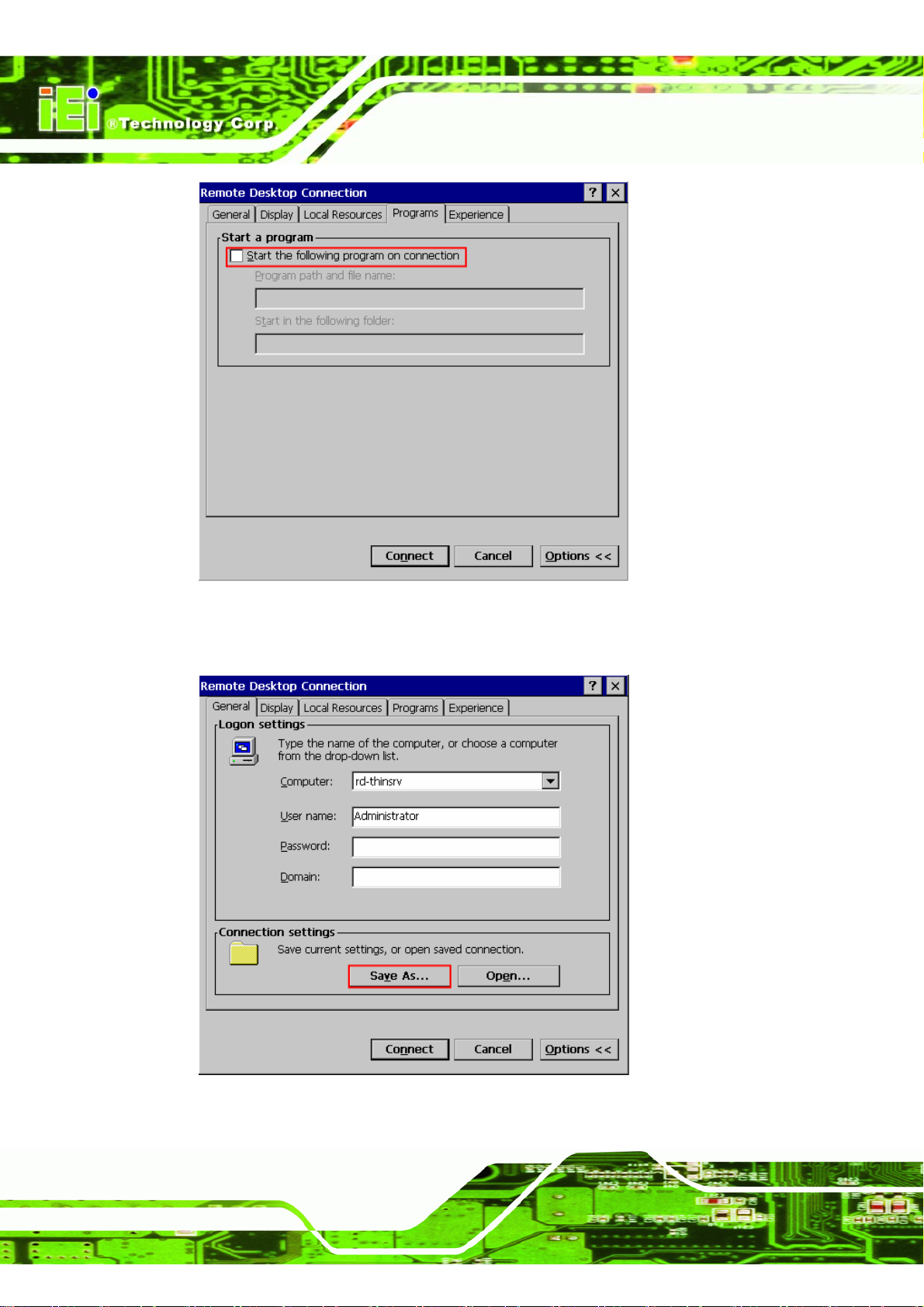
Step 4: Select Start Programs as the default application to start when you connect or
specify an application name. If you select to specify an application, you can also
specify a working directory.
Page 19
Page 34
IMK-571R Software and Programming Guides
Figure 1–32: Remote Desktop Programs Tab
Step 5: Click Save As to save the new connection.
Page 20
Figure 1–33: Remote Desktop General Tab
Page 35
IMK-571R Software and Programming Guides
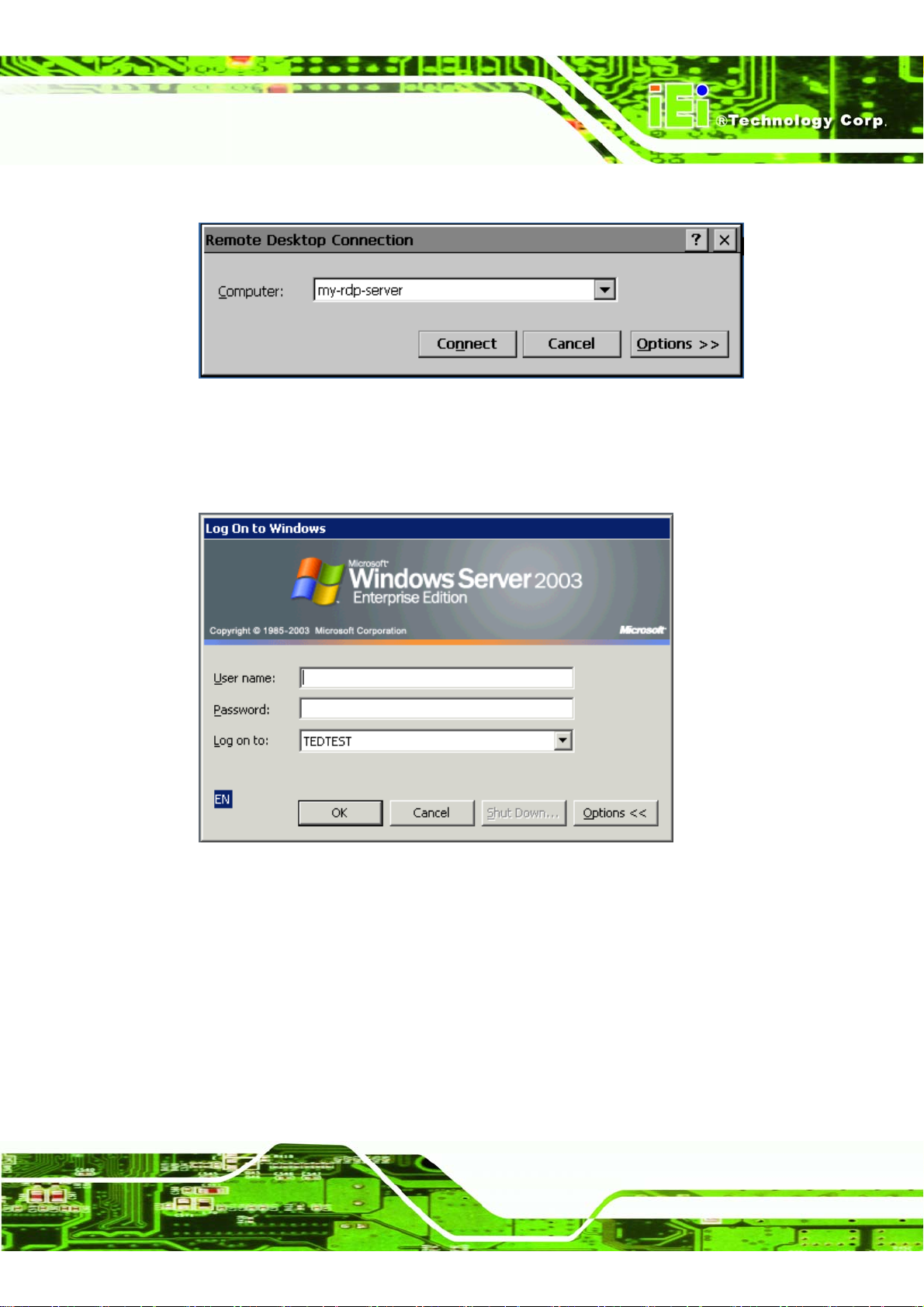
Step 6: Select the connection you created in Step 2. Then click Connect.
Figure 1–34: Remote Desktop Connection
Step 7: Enter the [User name], [Password] and [Domain] of the computer to connect to,
and click Connect.Step 0:
Figure 1–35: Windows Server 2003 Logon
1.4.3 Software-based Input Panel
A large-sized onscreen keyboard can be used for entering information.
Step 1: Click the SIP icon.
Page 21
Page 36
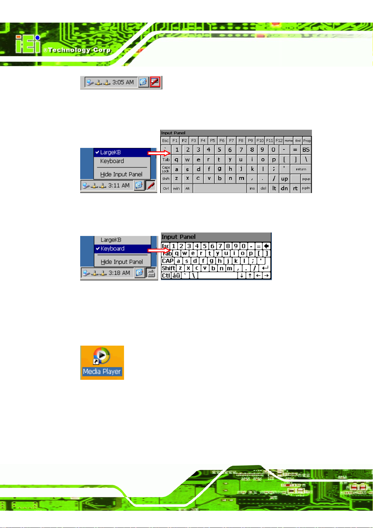
Figure 1–36: Software Keyboard Icon
Step 2: Select LargeKB.
Figure 1–37: Large Software Keyboard
Step 3: Or select Keyboard.Step 0:
IMK-571R Software and Programming Guides
Figure 1–38: Normal Software Keyboard
1.4.4 Media Player
Step 1: Double-click the Media Player icon.Step 0:
Figure 1–39: Media Player Desktop Icon
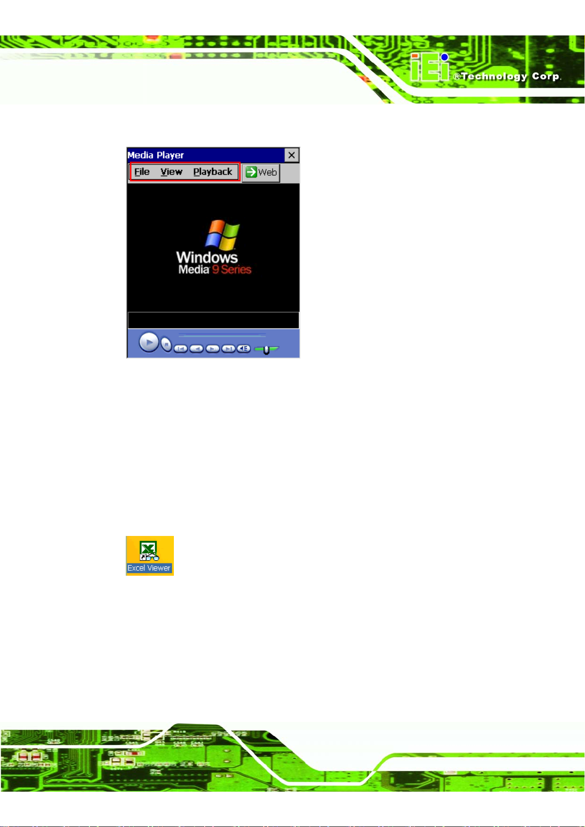
File: Use [Open], [Close], [Play lists], [Favorites] functions to control and manage the
Media File.
View: To control the appearance of the Media Player panel.
Page 22
Page 37
IMK-571R Software and Programming Guides
Playback: To control the playing status of Media Player.
Figure 1–40: Windows Media Player
1.4.5 File Viewer
File View enables you to view files created for various Microsoft® programs. You cannot
edit these files.
A File Viewer includes the following applications.
Microsoft® Excel Viewer: View, print and copy Excel documents.
Figure 1–41: Microsoft® Excel Desktop Icon
Microsoft® Word Viewer: View, print and copy Word documents.
Page 23
Page 38
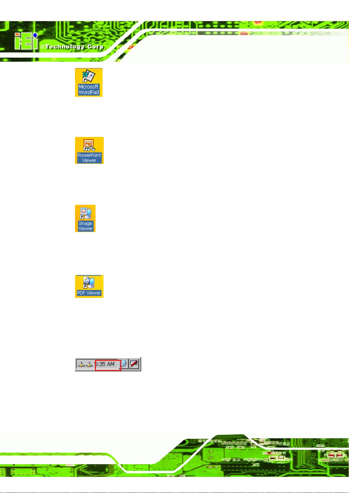
Figure 1–42: Microsoft® WordPad Desktop Icon
Microsoft® PowerPoint Viewer: View, print and copy PowerPoint documents.
Figure 1–43: Microsoft® PowerPoint Viewer Desktop Icon
Microsoft® Image Viewer: View, print and copy Image File.
IMK-571R Software and Programming Guides
Figure 1–44: Microsoft®® Image Viewer Desktop Icon
Microsoft® PDF Viewer: View, print and copy PDF documents.
Figure 1–45: Microsoft® PDF Viewer Desktop Icon
1.4.6 Setup System Time
Step 1: Double Click the Time to set the system time of your device.
Figure 1–46: System Time
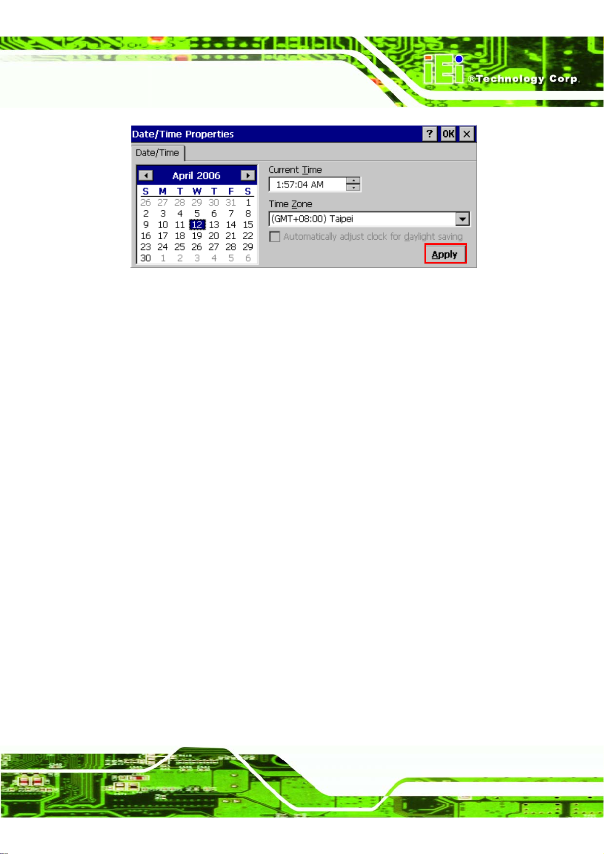
Step 2: Setting the Date/Time, Current Time, Time Zone.
Page 24
Step 3: Click Apply to complete setting.Step 0:
Page 39
IMK-571R Software and Programming Guides
Figure 1–47: Date/Time Properties
1.5 IEI CEUTILITY 1.0
1.5.1 Launching IEI CEUTILITY 1.0
To launch the utility, select Start Æ Programs ÆIEIÆIEI CEUTILITY 1.0. (the target
execution file is IEI_CEUTILITY.exe in “SYSTEM” dir ectory in your default SD Memory
Card file sy stem).
1.5.2 General Settings
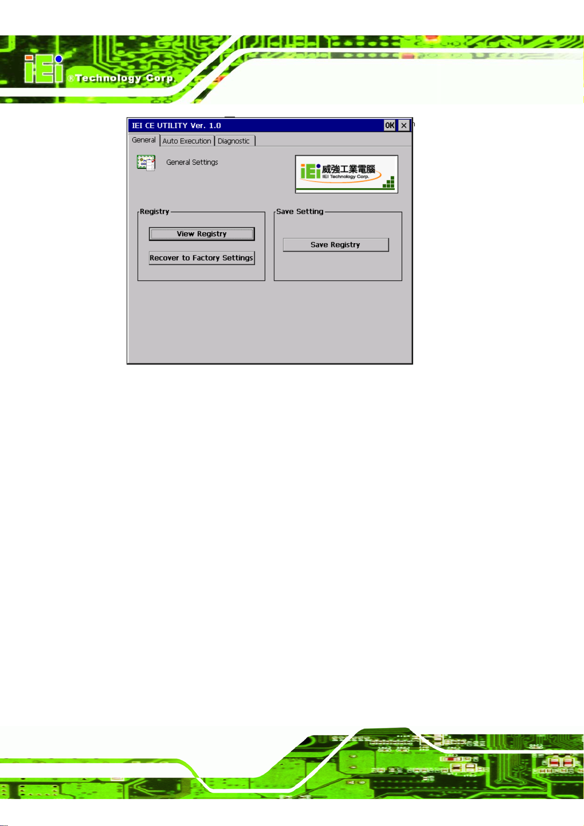
On this page, you can configure and save the Registry. The steps are illustrated as below:
Page 25
Page 40
IMK-571R Software and Programming Guides
Figure 1–48: IEI CE Utility
1.5.2.1 Registry Settings
You can view your device registry keys and values by clicking the “View Registry” button.
If you want to restore system registry to default factory settings, click “Recover to Factory
Settings”, before you do this, make sure all custom applications are no longer associated
with any user-defined registry keys, since these keys cannot be recovered again and
would be erased.
1.5.2.2 Save Registry Settings
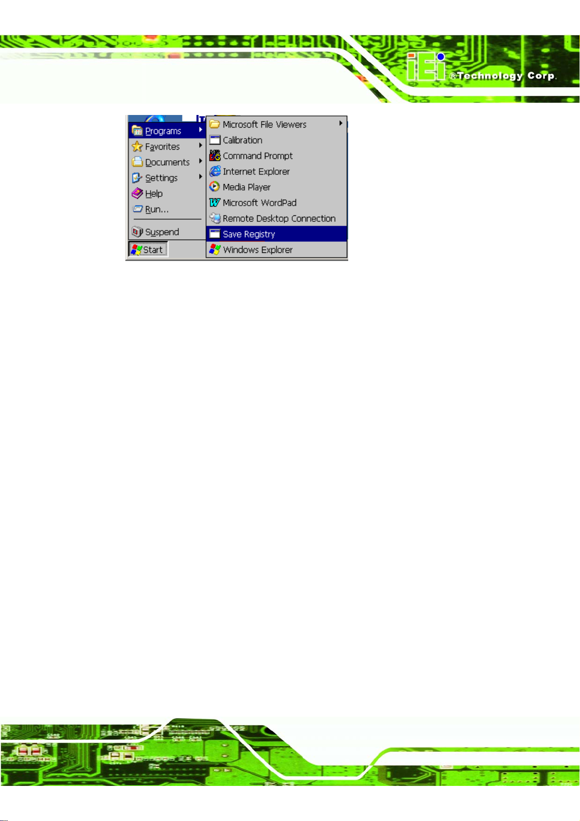
Same function as Save Registry in the Start Menu.
Page 26
Page 41
IMK-571R Software and Programming Guides
Figure 1–49: Save Registry
Saves all changes to non-volatile memory so they are not lost when the system is
restarted.
1.5.3 Auto Execution
Programs can be set to load when the device is turned on. The programs are loaded from
the top of the list to the bottom.
To add a new program to the list, double-click the last (empty) row or click the "Add"
button. Alternatively, click the "…" or double-click to select from the file dialog box.
Select and item and click "Edit" to change the path of an entry.
Highlight an item then click "Delete" to remove it from the list.
Adding an executable into the path list.
Page 27
Page 42
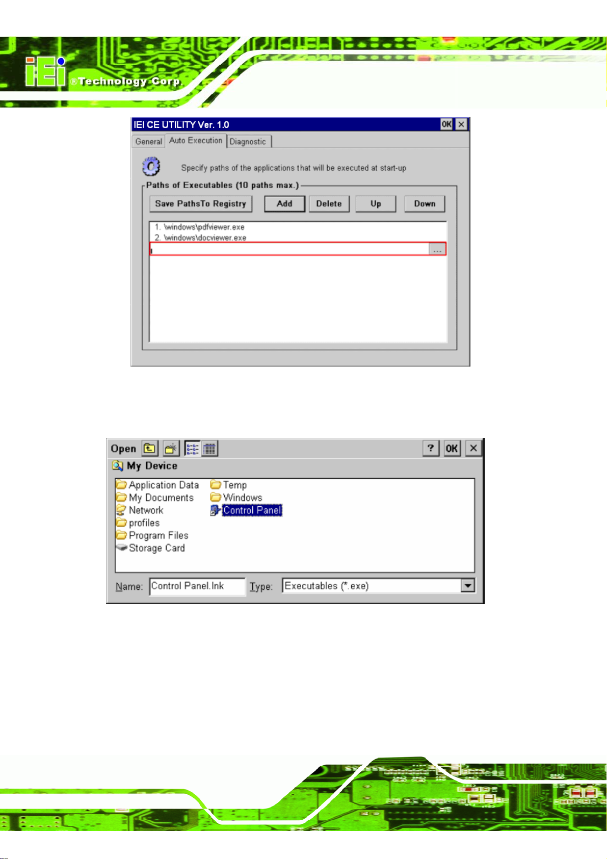
Figure 1–50: Auto Execution
IMK-571R Software and Programming Guides
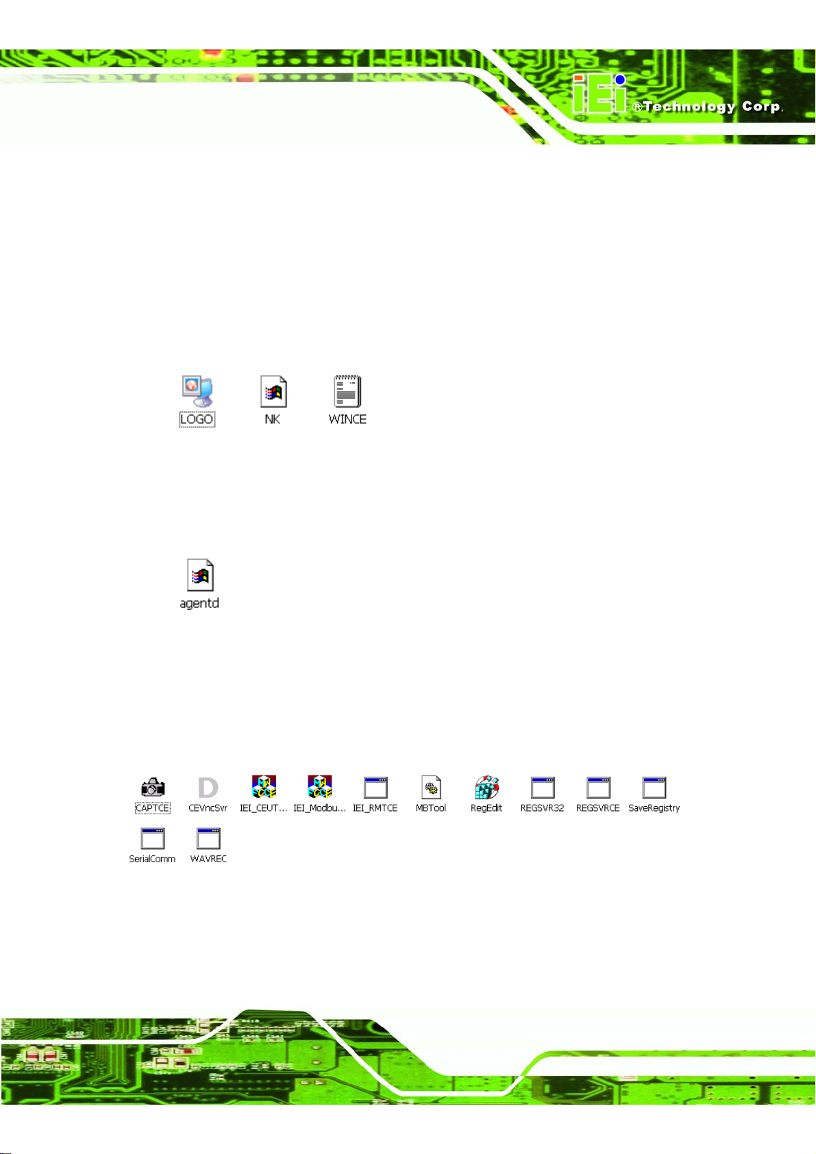
To chose an application path from the file dialog box
Figure 1–51: Auto Execution Choose Program Dialog
Page 28
Page 43
IMK-571R Software and Programming Guides
1.6
Contents of Default Secure Digital Card memory card
1.6.1 OS Image, Logo File and Configuration File
The Windows CE 5.0 OS Image file (NK.bin), the picture for boot up screen (LOGO.bmp)
and the configure file (WINCE.TXT) should be located in root of file system of SD Memory
Card. For details about the configuration file, please refer to section 2.7.
My DeviceÆ Storage Card.
Figure 1–52: OS Image, Startup Logo and Configuration File
Also in the storage card is “agentd.log”. This is a log file automatically generated by
IEI_RMTCE, the Windows CE agent of Remote Management tools.
Figure 1–53: IEI_RMTCE Log File
1.6.2 List of applications in system folder
A directory named “SYSTEM” in the default SD Card file system contains system files,
utilities, and sample applications. Please select My DeviceÆ Storage Card ÆSystem
Figure 1–54: System Directory
Page 29
Page 44
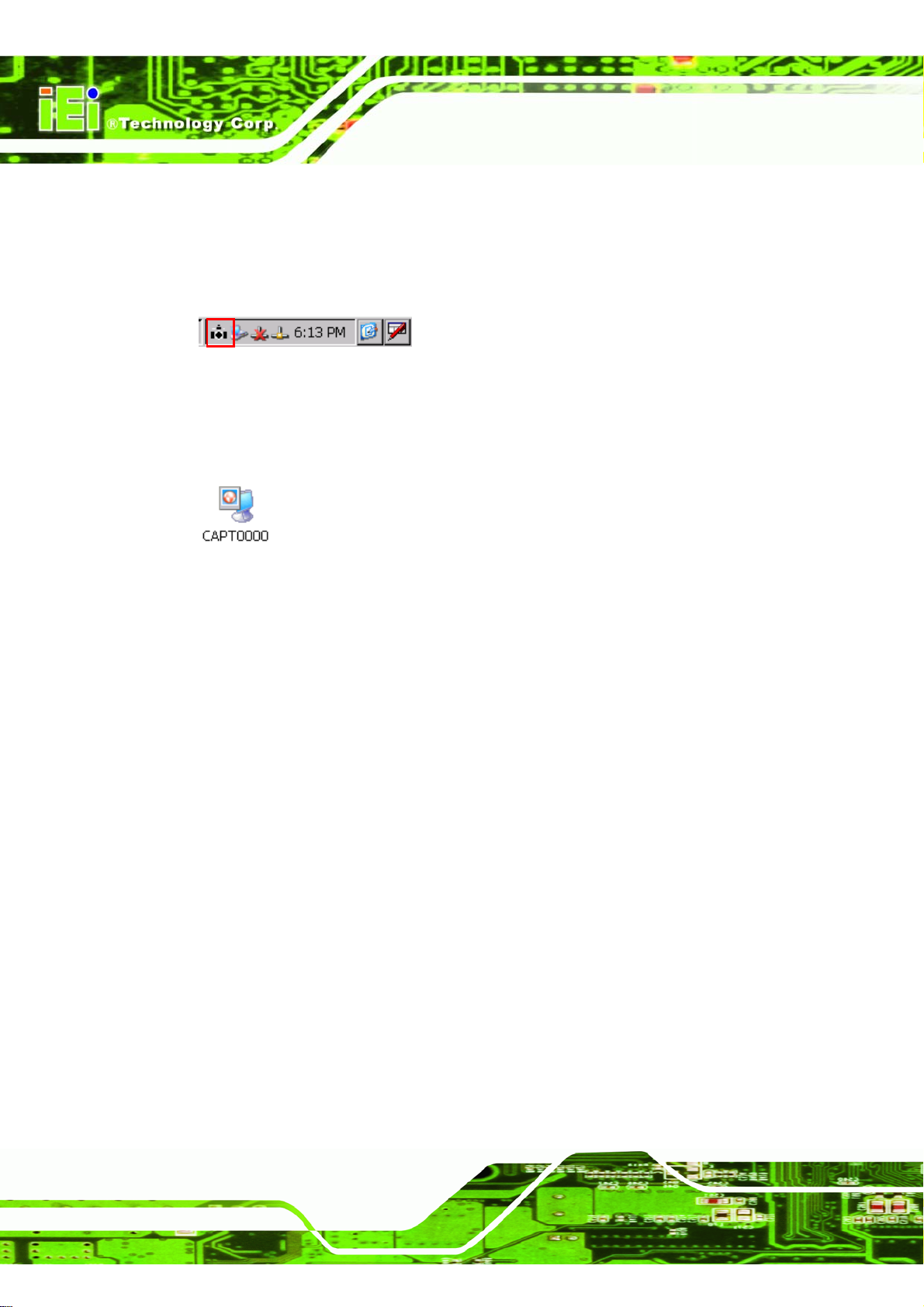
1.6.2.1 Screen Capture
The screen capture software will take a picture of what is on the screen. Double-click
“CAPTCE.exe” to start the application. It appears in the bottom right-hand corner.
Figure 1–55: Screen Capture Icon
Tap this icon to capture the screen to a bitmap file named “CAPT000n.bmp” in the
directory “My Device”.
Figure 1–56: Screen Capture
IMK-571R Software and Programming Guides
1.6.2.2 IEI_RMTCE & CEVncSvr
IEI_RMTCE.exe is the Windows CE agent of IEI Remote management tools. It is
executed automatically in Windows CE device side while your Windows CE device started,
and it would wait for communication with PC side remote manager of IEI Remote
Management tools. Please refer to Chapter 4.1.4. for details of IEI Remote
Management tools.
1.6.2.3 IEI_CEUTILITY
IEI Windows CE device utility for configuring, managing, updating, and diagnostics of y our
IEI ALCHEMY AU1250 RISC-based Windows CE 5.0 devices. Please refer to chapter 2.5.
for details.
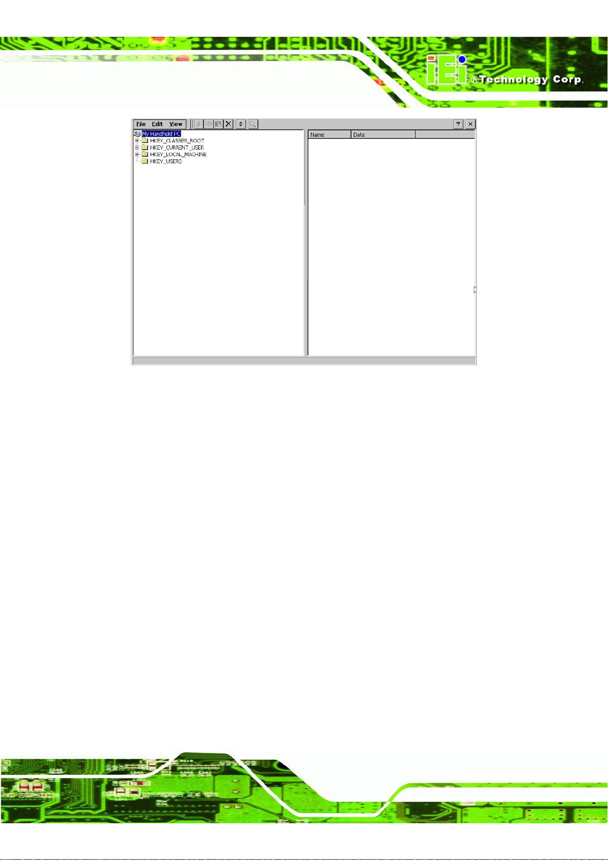
1.6.2.4 RegEdit
This program would help customers to view and edit the settings in your Windo ws CE
devices.
Page 30
Page 45
IMK-571R Software and Programming Guides
Figure 1–57: Registry Editor
1.6.2.5 REGSVR32 & REGSVRCE
Execute these at the DOS command prompt.
REGSVR32:
Function: Register or Unregister a DLL.
Syntax: REGSVR32 [/U] [/S] [/C] [/I: [Command_Line]] DLL_Name
REGSVR32 [/U] [/S] [/C] /N /I: [Command_Line] DLL_Name
Switches: /u -Unregister Server.
/s -Silent ;no dialogue boxes.
/c -Console output.
/n -Don't call DllRegisterServer
/i -Call DllInstall (or DllUninstall if /u is specified)
Command Line An optional command line for DllInstall.
REGSVRCE:
Function: Register or Unregister a DLL.
Page 31
Page 46
Syntax: REGSVRCE [/U] [/S]: [Command_Line]] DLL_Name
Switches: /u -Unregister Server.
1.6.2.6 Save Registry
Saves any settings made to the registry. If not saved, settings will return to their original
values when the system is reset.
IMK-571R Software and Programming Guides
/s -Silent; display no message boxes.
Figure 1–58: Save Registry
1.7 Configuration File
1.7.1 Overview
The configure file (WINCE.txt) is located in the root directory of SD Memory Card. It loads
and erases the EEPROM, adjusts the screen resolution and the COM2 mode.
Page 32
Page 47
IMK-571R Software and Programming Guides
============================================================================
offset value
============================================================================
* 0x00 0x00 // load registry from EEPROM
* 0x01 0x00 // erase registry in EEPROM
* 0x02 0x01 // display type: 0x01 = LTM04C380K (640 x 480)
// 0x0a = G104SN03 (800 x 600)
// 0x0d = FG070050DNCWAG01 (800 x 480)
* 0x03 0x00 //com2 mode: 0x00 = RS-232
EOF
The asterisk (*) indicates a line with a setting. The offset value should not be changed, but
the value can be changed according to required settings. Anything after a double slash (//)
is a comment.
1.7.2 Offset 0x00: Load Registry From EEPROM
0x00: loads default registry and skips loading from EEPROM.
0x01: loads registry from EEPROM.
1.7.3 Offset 0x01: Erase Registry in EEPROM
0x00: current registry is not erased.
0x01: registry erased during boot.
If the system hangs after boot, try setting this to 0x01, then restarting the system to
erase the registry.
1.7.4 Offset 0x02: Display Type
Don't change this value, if the setting does not matc h the screen resolution, the image
won't display properly.
Page 33
Page 48
IMK-571R Software and Programming Guides
Chapter
2
2 Using the Remote
Management Tool
Page 34
Page 49
IMK-571R Software and Programming Guides
2.1 About IEI Remote Management Tools
2.1.1 Overview
IEI Remote Management Tools allow simple, centralized control of multiple Windo ws CE
devices. These tools are developed specifically for I EI XScale PXA270 Windows CE 5.0
devices, IPXA270-DK01 development kits and IEI RMI Alchemy AU1250 Windows CE 5.0
devices.
2.1.2 Important Features of the IEI Remote Management Tools
Managing IEI Windows CE devices remotely
Automatic search and verification of available IEI Windows CE devices in the
network
Remote wakeup, restart & shutdown
Remote modification of thin client settings
Remote adding and deleti ng of RD P settings
Monitor settings of thin clients including device name, IP address, MAC
address, firmware version and agent program
Supports firmware update for single or multiple devices via FTP
Provides current status and event record
Current status monitoring
2.1.3 System Requirement
The IEI Remote Management Tools can be installed in the following OS:
®
Windows
Windows
Windows
XP Pro
®
2000/ Pro/ Server
®
2003/ Server
2.1.4 Concept
The IEI RMT(Remote Management Tools) includes two main categories:
Step 1: IEI Remote Manager: is installed on the PC with Microsoft® Windows or
Windows Server.
Page 35
Page 50
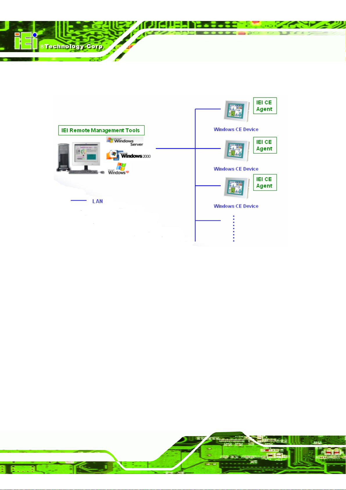
Step 2: IEI CE Agent: is installed in the SD Memory Card file system. This starts
automatically when the system is started. Step 0:
IMK-571R Software and Programming Guides
Figure 2–1: Remote Management Tools Overview
The following sections describe how to setup the remote management tool.
2.2 To Install IEI Remote Management Tools
To install the remote management tool.
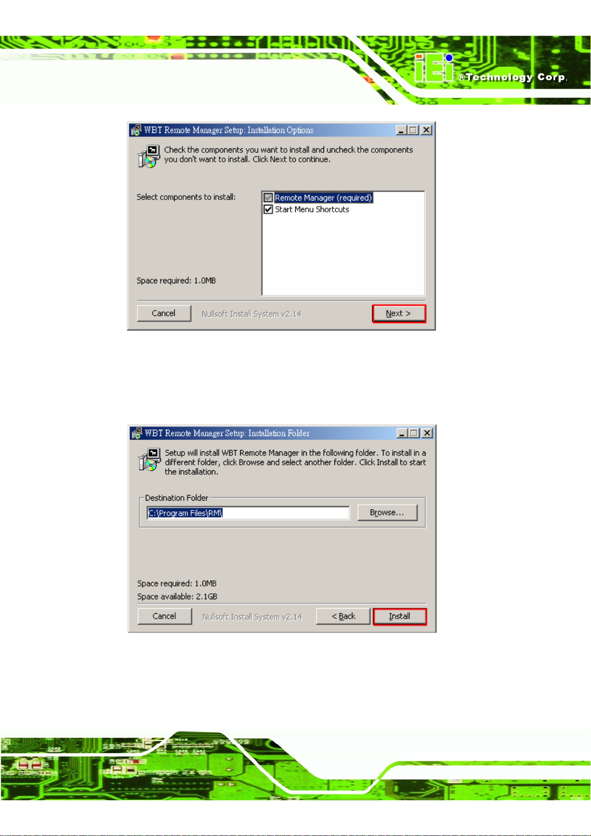
Step 1: Run IEI Remote Management Tools setup from the CD-ROM (\IEI Remote
Management Tools\ IEI_RMT.exe). Select the components to install and click
Next.
Page 36
Page 51
IMK-571R Software and Programming Guides
Figure 2–2: Remote Management Setup Installation Options
Step 2: Specify the destination folder that the program is installed to and click Install. (If
unsure, leave the default)
Figure 2–3: Remote Management Setup Installation Folder
Step 3: When installation completes, click Close.Step 0:
Page 37
Page 52
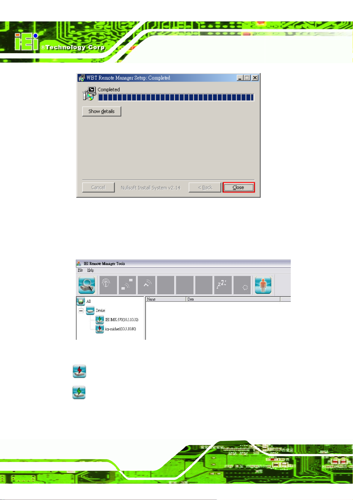
Figure 2–4: Remote Management Setup Completed
IMK-571R Software and Programming Guides
2.3 Remote Management Tools
IEI Windows CE devices online/ offline status
Figure 2–5: Remote Management
device is offline now
device is online now
Page 38
Page 53
IMK-571R Software and Programming Guides
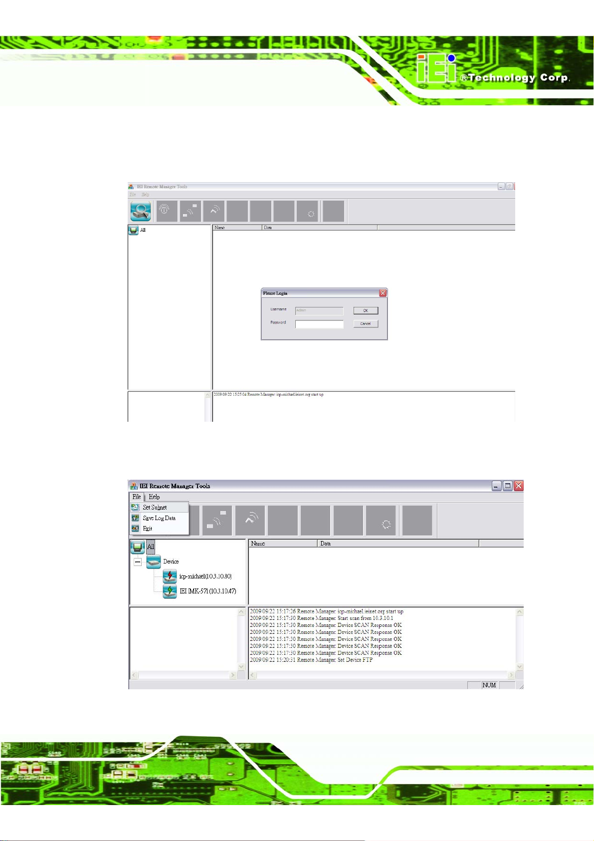
Step 1: After installing IEI Remote Management Tools run the program. The following
window will be shown: Default Password: Admin
Figure 2–6: Remote Management
Step 2: Select Set Subnet from File on the toolbar.
Figure 2–7: Remote Management Set Subnet
Page 39
Page 54
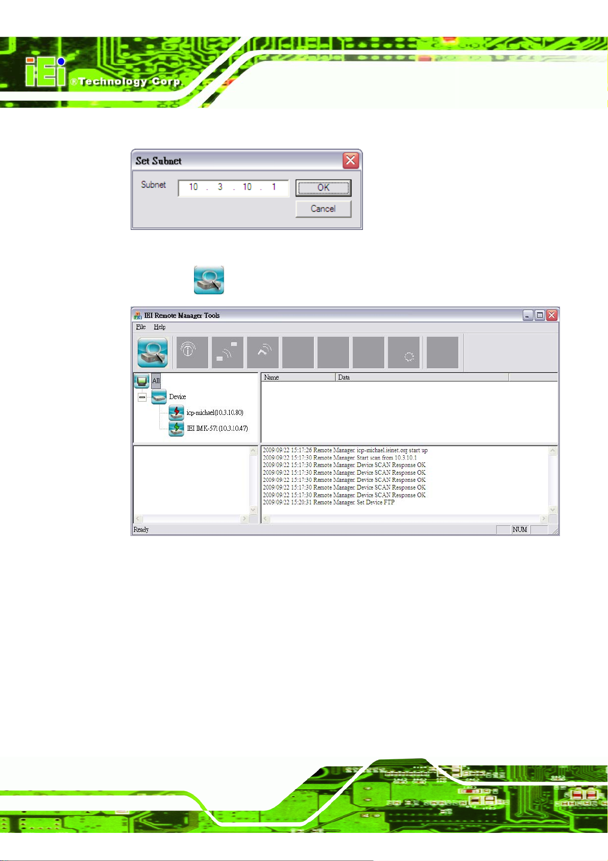
Step 3: Enter the subnet for monitoring IEI Windows CE devices.
Figure 2–8: Remote Management Set Subnet
IMK-571R Software and Programming Guides
Step 4: Click
Figure 2–9: Remote Management Device Search
to search for all available IEI Windows CE devices in the subnet.
2.4 Wake up/ Configure/ Update/ Connect an IEI Windows CE
device
Page 40
The IEI Remote Management Tools can be used to wake up, configure, update and
connect to IEI Windows CE devices remotely.
Page 55
IMK-571R Software and Programming Guides
2.4.1 Connect Remote Device
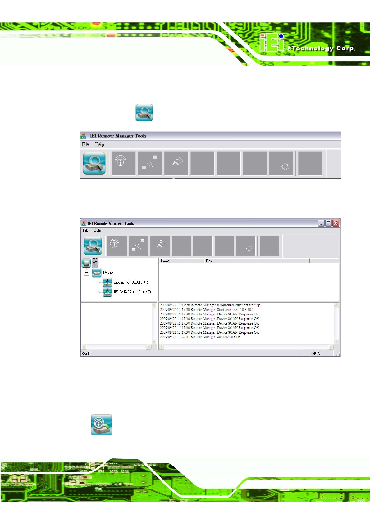
Step 5: To connect to an IEI Windows CE device, run the IEI Remote Management
Tools. Click
Figure 2–10: Search for Devices
Step 6: The devices will be shown on the left column.Step 0:
to search for all available IEI Windows CE devices.
Figure 2–10: Device List
2.4.2 Configure an IEI Windows CE device
To configure an IEI Windows CE device, select the device on the left column and then
click
(Terminal Property) on the toolbar.(After you pass the security check.)
Page 41
Page 56
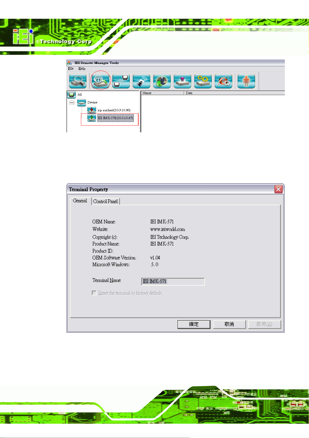
Figure 2–112: Terminal Properties
2.4.2.1 General
You can view the general information of the device in this page.
IMK-571R Software and Programming Guides
Figure 2–123: Terminal Properties General Tab
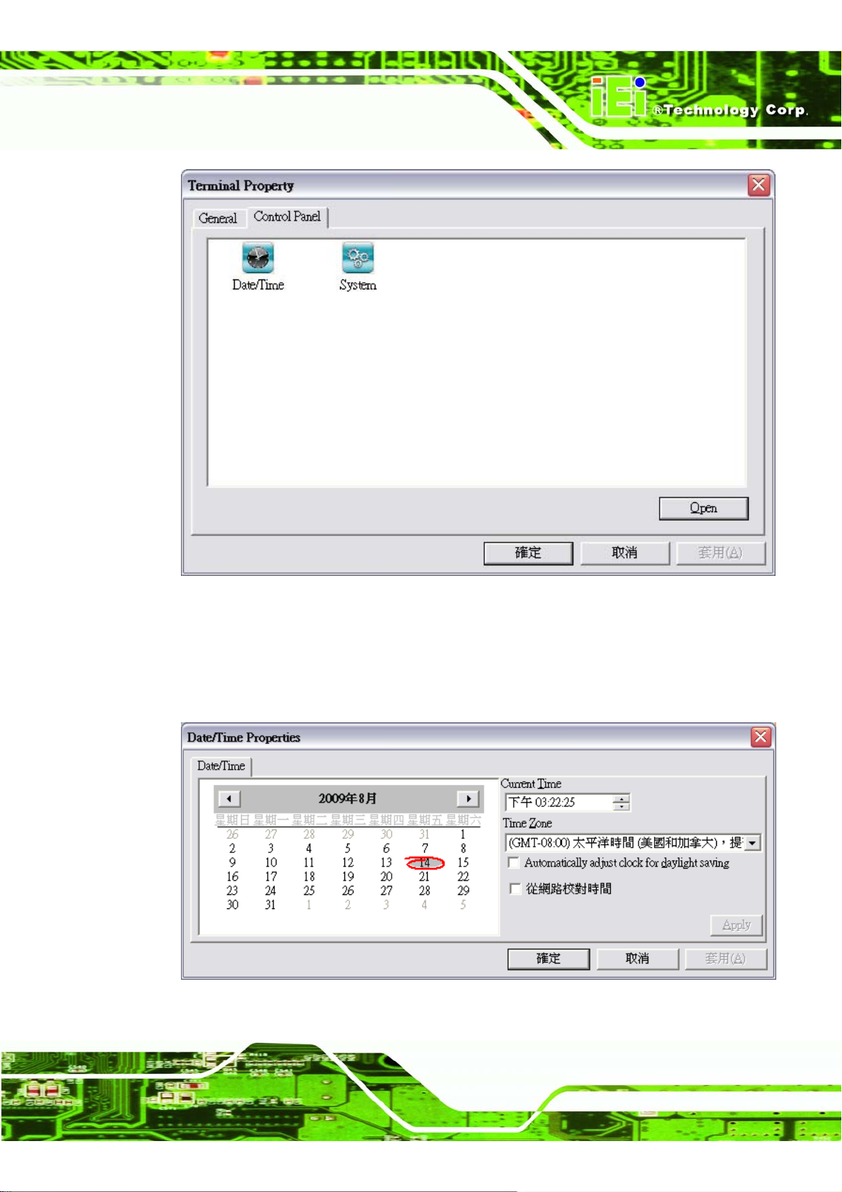
2.4.2.2 Control Panel
Control Panel enables you to modify functions available for a device .
Page 42
Page 57
IMK-571R Software and Programming Guides
Figure 2–15: Terminal Properties Control Panel Tab
2.4.2.2.1 Date & Time
Set the time of the device.
Figure 2–16: Set Device Time
Page 43
Page 58
IMK-571R Software and Programming Guides
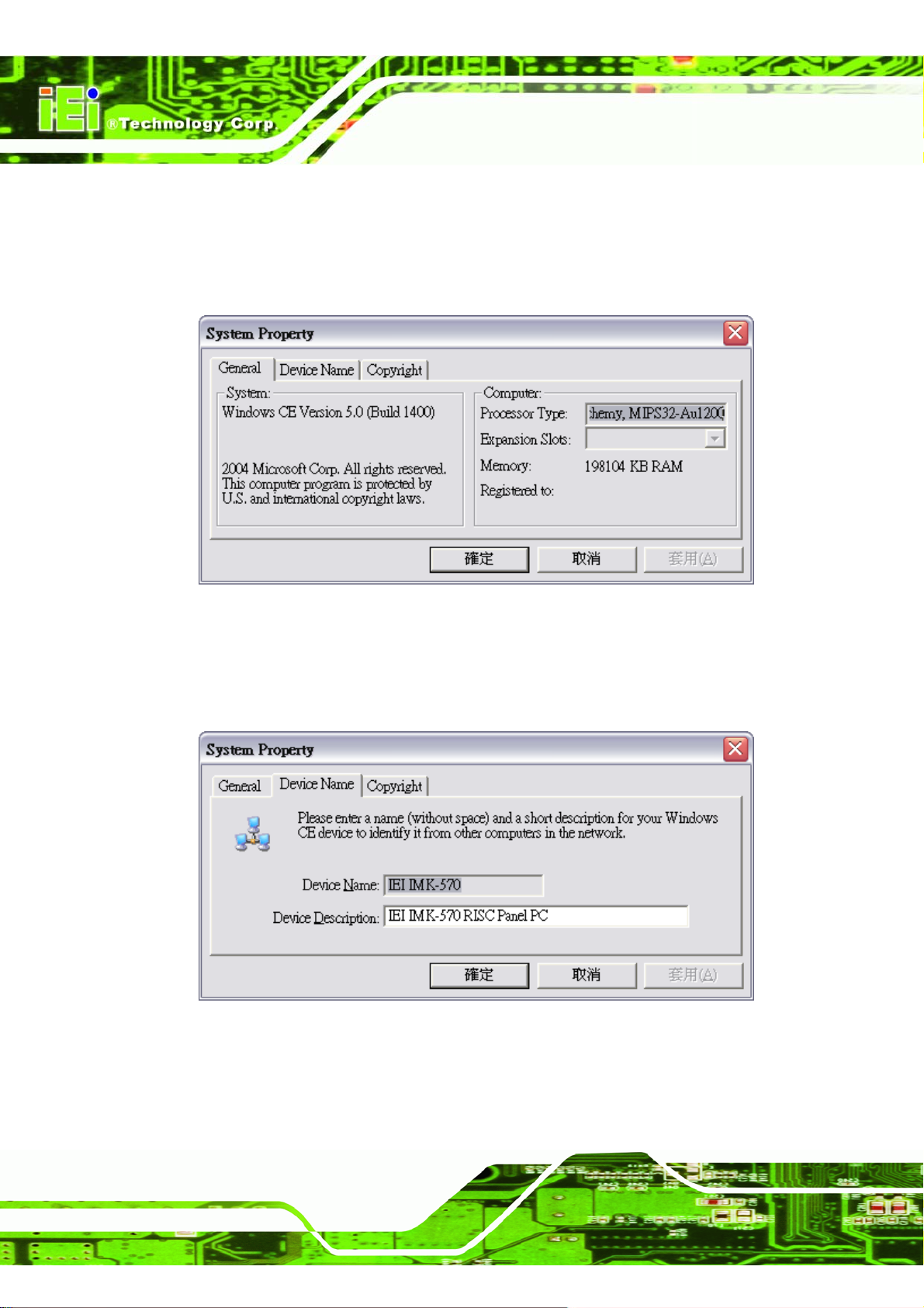
2.4.2.2.2 System Property
General
This section displays device information.
Figure 2–17: System Property General Tab
2.4.2.2.3 Device Name
This section shows name of the device. You can enter a description here.
Figure 2–18: System Property Device Name Tab
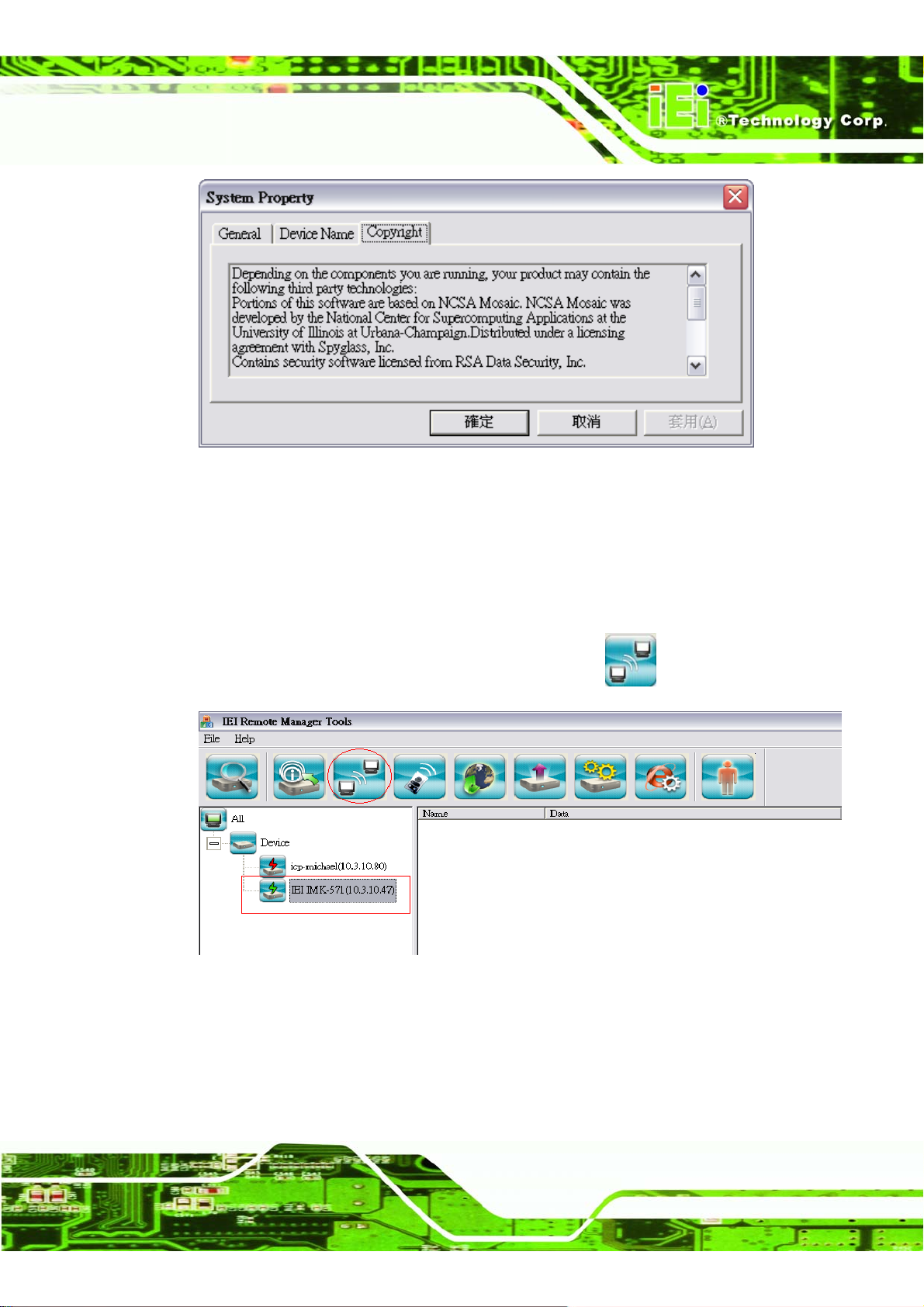
2.4.2.2.4 Copyright
Page 44
This section displays the copyright of the device.
Page 59
IMK-571R Software and Programming Guides
Figure 2–19: System Property Copyright Tab
2.4.2.3 Define Terminal Connection of an IEI Windows CE Device
Please follow the steps below to configure RDP connection of Thin Client via Remote
Manager.
Step 1: Select the device name on the left column and click
Figure 2–20: RDP Connection Properties
Step 2: The following screen appears.
(RDP).
Page 45
Page 60
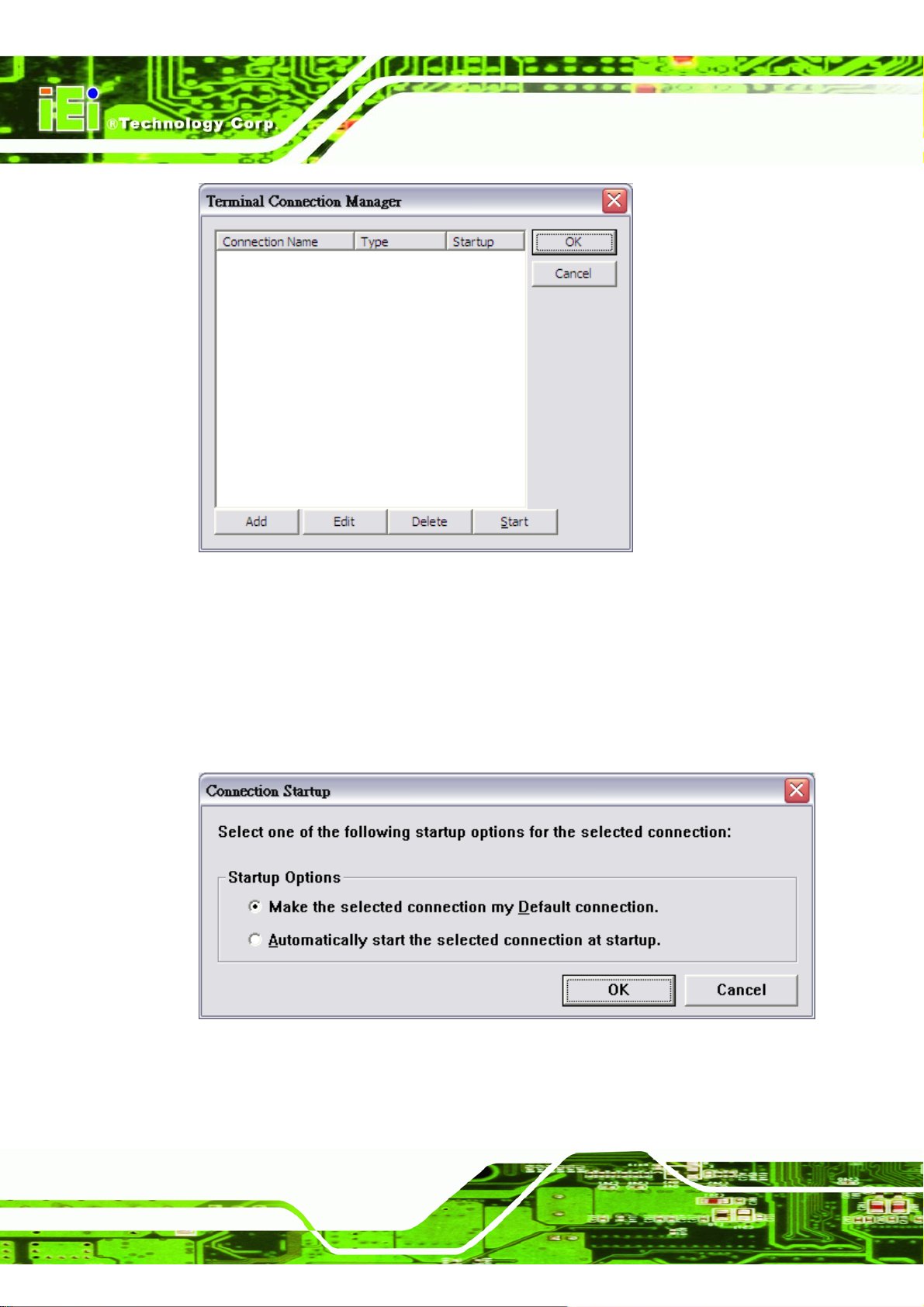
Figure 2–21: Terminal Connection Manager
IMK-571R Software and Programming Guides
Step 3: Click Add to add a new connection.
Step 4: To edit an existing connection, select the item and click Edit.
Step 5: To set the startup option for the connection, click Start. Select the startup option
and click OK.
Figure 2–22: Connection Startup
Page 46
Step 6: To delete a connection, select the item and click Delete.
Page 61
IMK-571R Software and Programming Guides
Step 7: After completing the settings, click OK to confirm or Cancel to quit.Step 0:
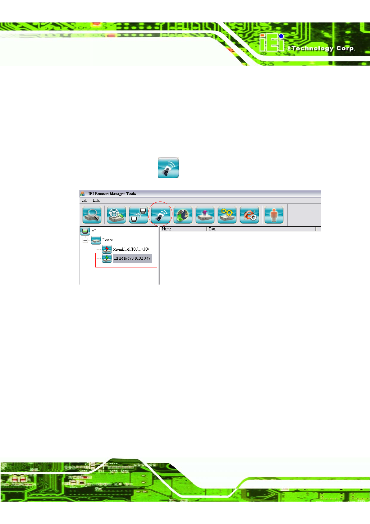
2.4.2.4 Remote Desktop Display
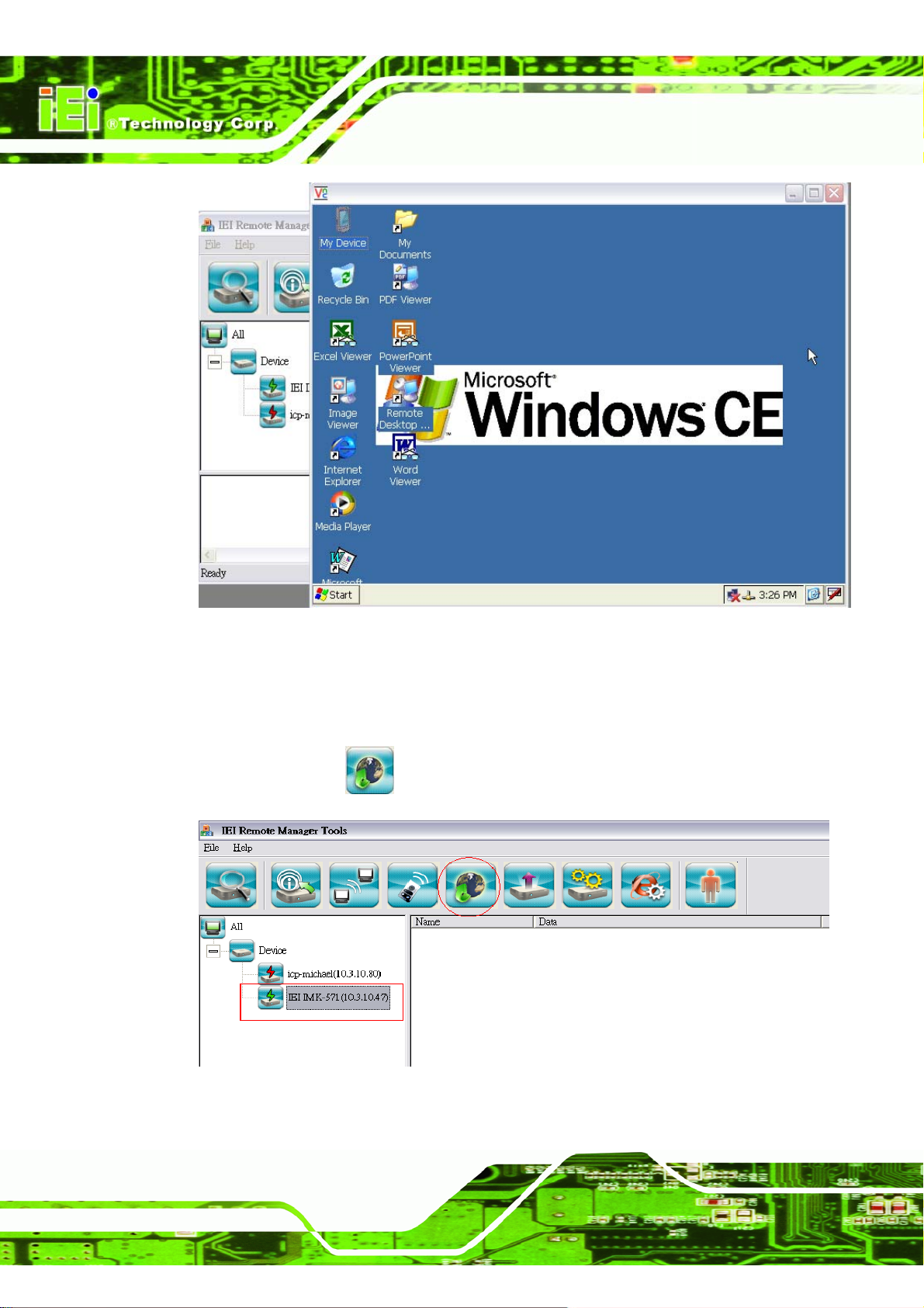
You can use VNC to view a real time desktop display of any connected IEI Windows CE
devices directly and control their mouse and keyboard just like being at the terminal.
Step 1: To use the VNC function, run Remote Manager. Select a connected IEI Windows
CE device and click
Figure 2–23: VNC Connection Properties
Step 2: The desktop of the connected dev ic e is shown in a new window.Step 0:
(VNC) on the toolbar.
Page 47
Page 62
IMK-571R Software and Programming Guides
Figure 2–24: Client PC VNC Viewer
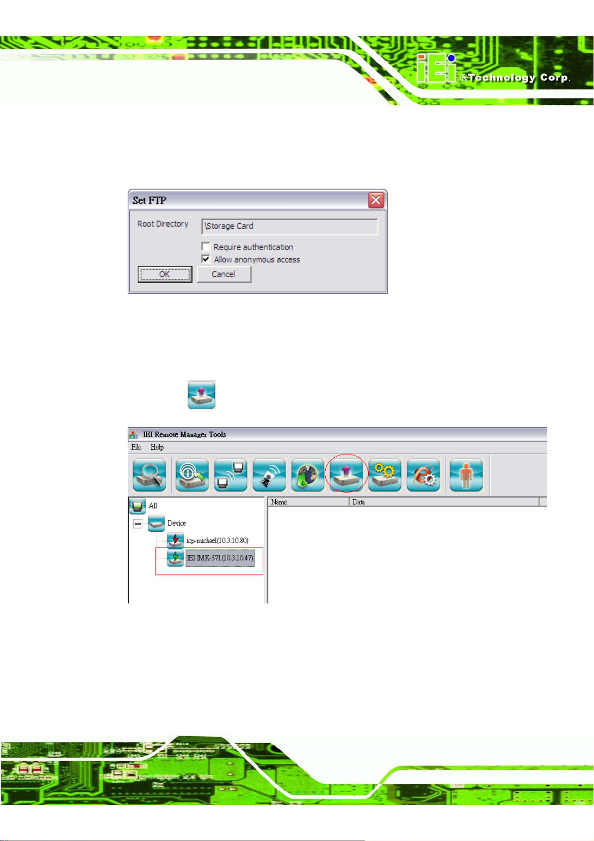
2.4.2.5 Configure FTP Settings of an IEI Windows CE device
Step 1: This option is used to configure FTP settings of devices. Select a device on the
left and click
(FTP) on the toolbar.
Page 48
Figure 2–25: FTP Connection Settings
Page 63
IMK-571R Software and Programming Guides
Step 2: The root directory of FTP service will be shown. Select the authentication
method and click OK.
Step 3: The Windows CE device will automatically reset so changes take effect.Step 0:
Figure 2–26: Set FTP Directory
2.4.2.6 Update an IEI Windows CE device
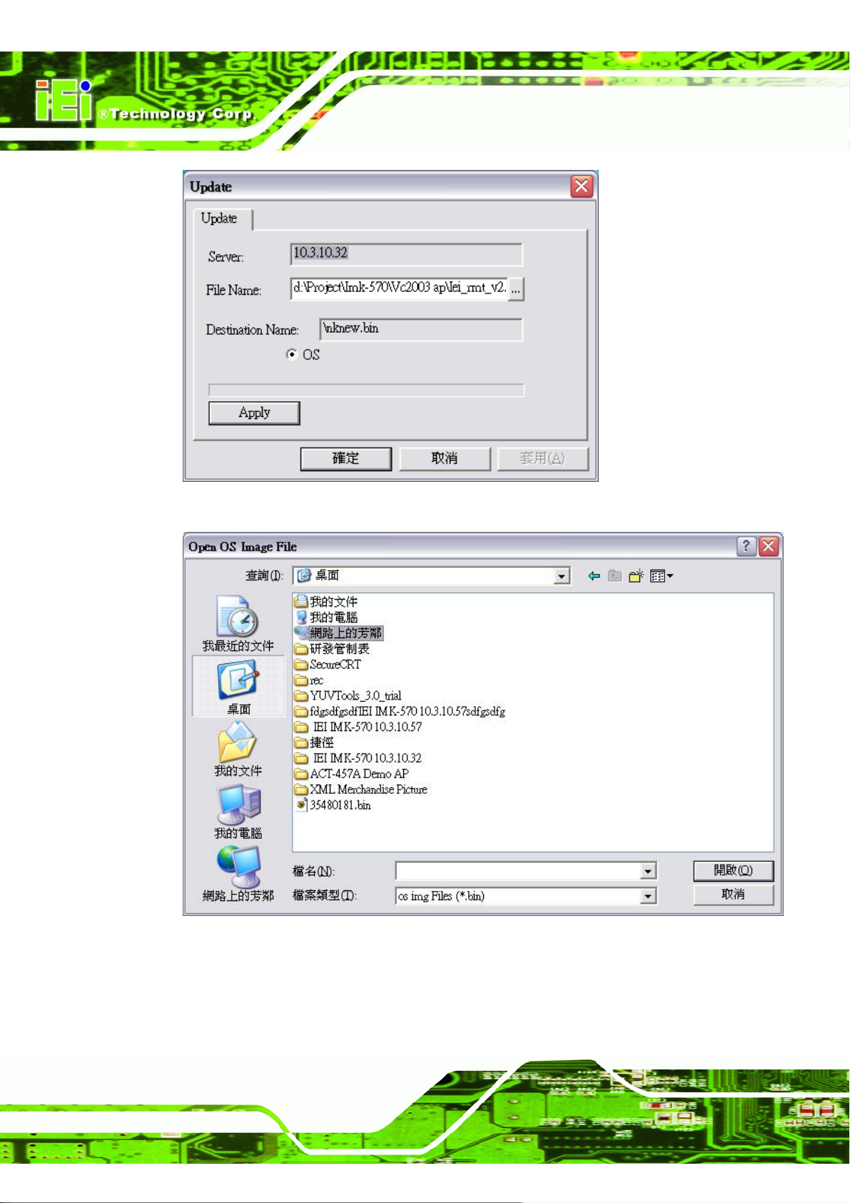
Step 1: To update an IEI Windows CE device, select a device on the left column and
click
Figure 2–27: Device Update
Step 2: Select to update BIOS or OS of the device.
Step 3: Select the appropriate file for updating and click Apply.Step 0:
(UPDATE).
Page 49
Page 64
IMK-571R Software and Programming Guides
Figure 2–28: Device Update Dialog
Page 50
Figure 2–29: Browse for System Image
Page 65
IMK-571R Software and Programming Guides
2.4.2.7 Record Logs for WBT
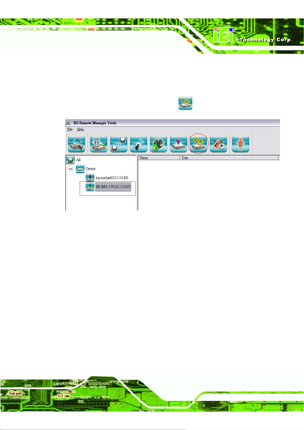
Step 1: This function enables network administrator to download log records of the thin
client and check against the logs in case of any device error. To download the
log file, select a connected client and click
Figure 2–30: System Logs
Step 2: When the following screen appears, browse and select the location to save the
file. Click Apply then OK to confirm.Step 0:
(LOG) on the toolbar.
Page 51
Page 66
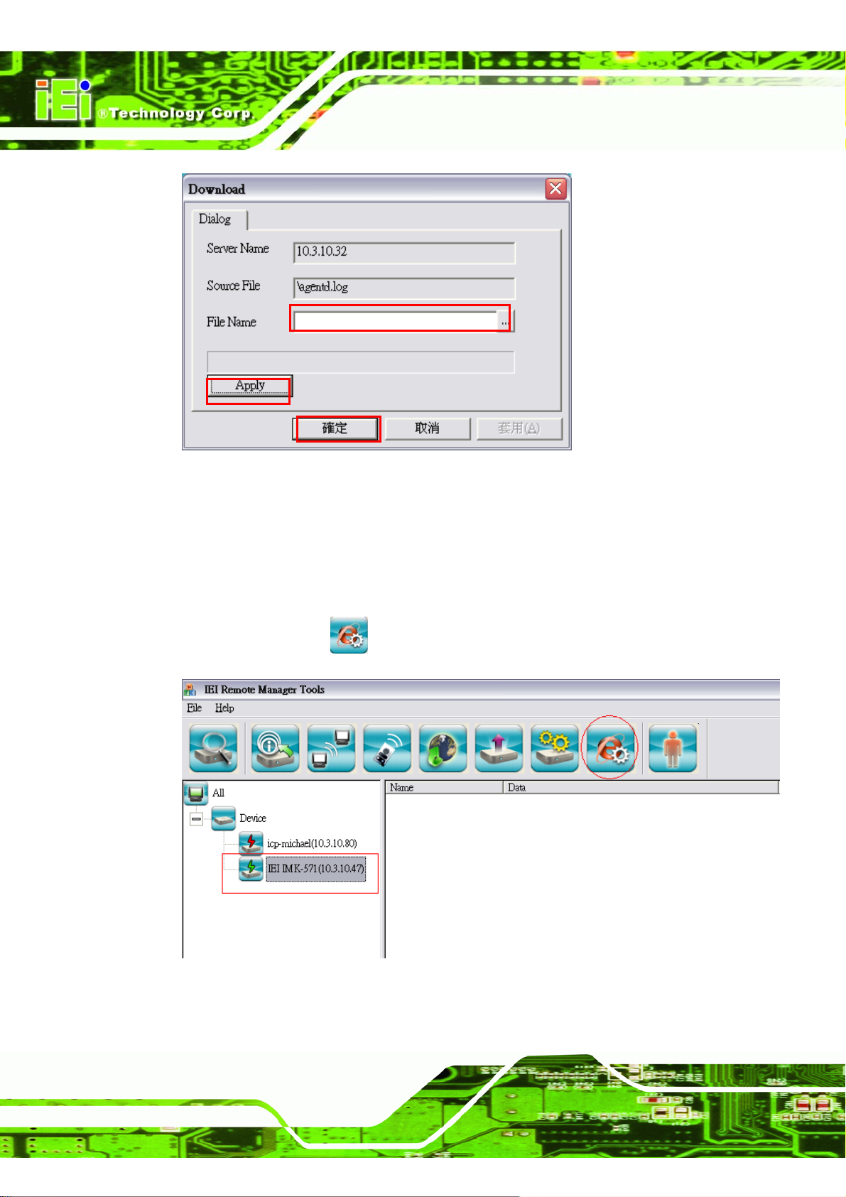
Figure 2–31: Log Download Dialog
IMK-571R Software and Programming Guides
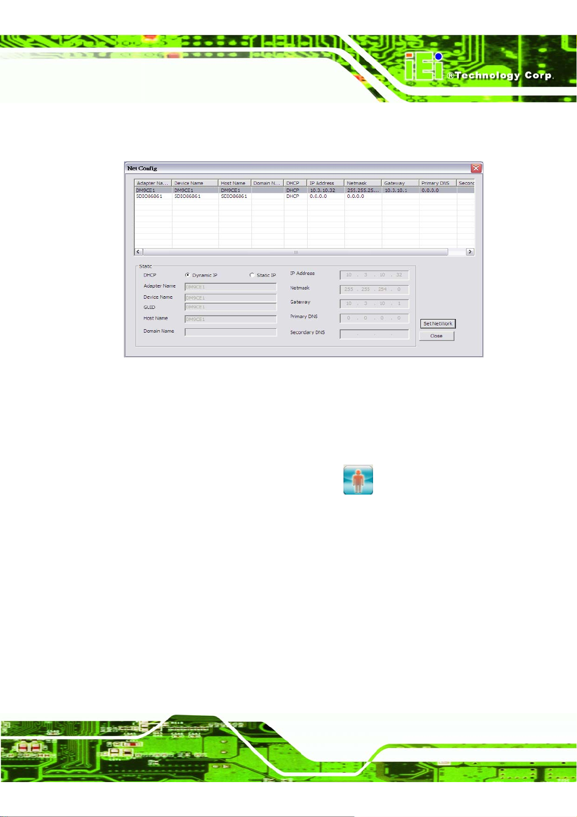
2.4.2.8 Network Parameter Configuration
Step 1: This function enables network administrator to set up the network parameter of
indicate devices. To set up the parameter of indicate devices, select a connected
client and click
(NetConfig) on the toolbar.
Page 52
Figure 2–32: Network parameter configuration
Page 67
IMK-571R Software and Programming Guides
Step 2: When the following screen appears, browse and set up the network parameter
of indicate devices. Click Set Network to confirm.Step 0:
Figure 2–33:Net Config Dialog
2.4.2.9 Account management
Step 1: This function enables network administrator to add or modify account
information of indicate devices. To add or modify account information of indicate
devices, select a connected client and click
(Account) on the toolbar.
Page 53
Page 68
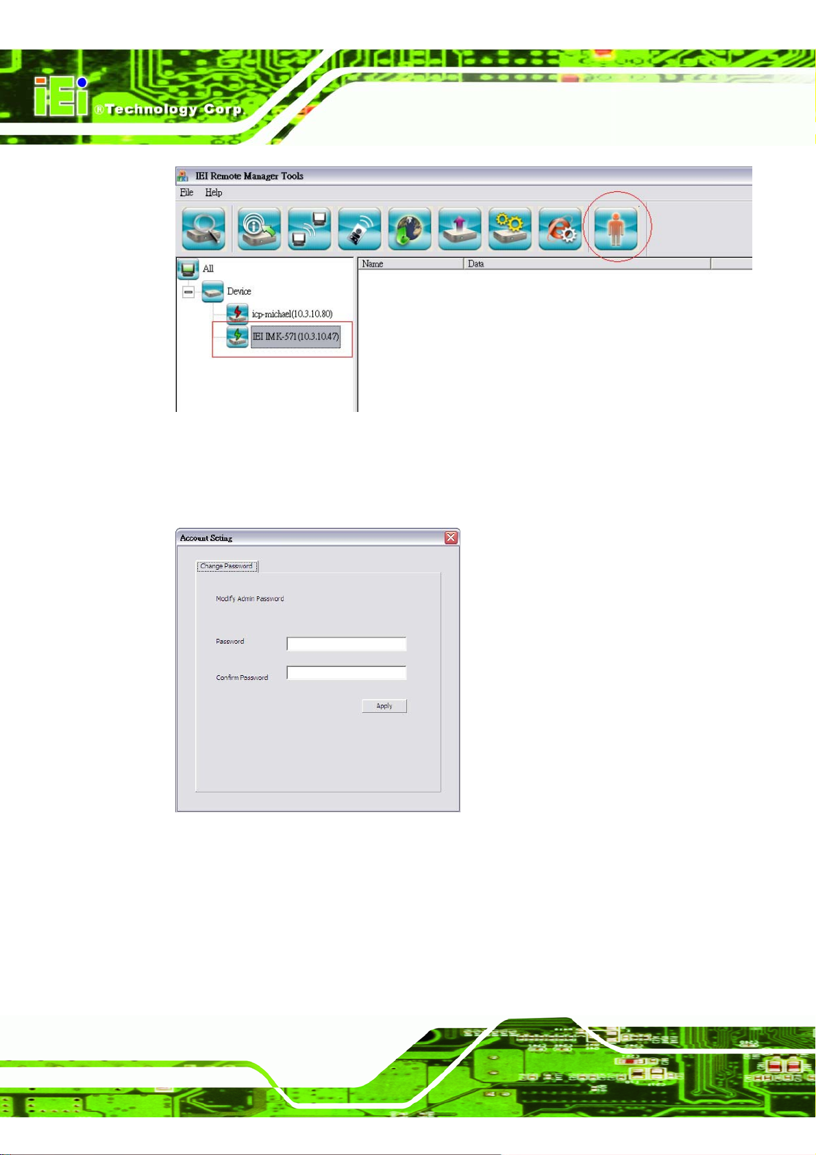
Figure 2–34: Account management
Step 2: When the following screen appears, modify Administrator’s password. Click
Apply to confirm.
IMK-571R Software and Programming Guides
Page 54
Figure 2–35:Account Setting Dialog -> change Admin password
Page 69
IMK-571R Software and Programming Guides
3 IMK Runtime Demo
Chapter
3
Page 55
Page 70
3.1 Demo Path
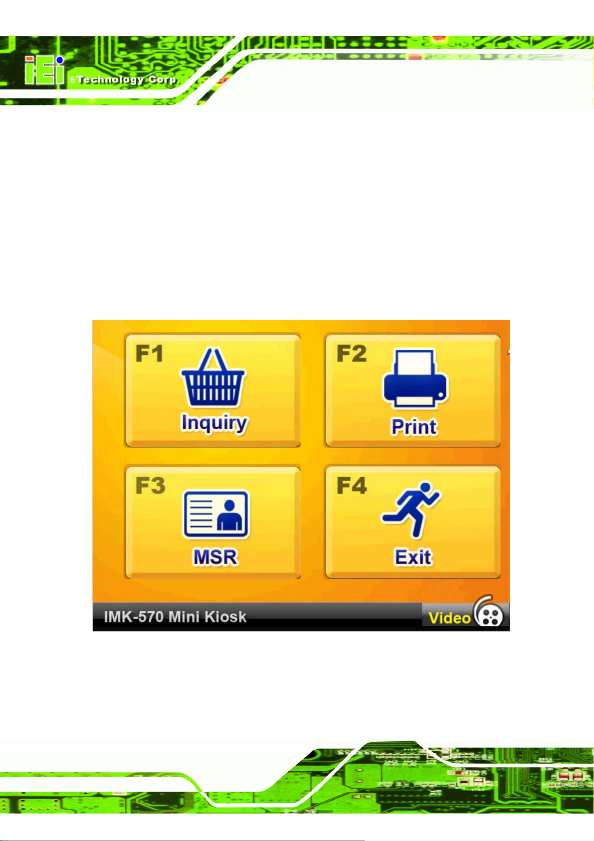
Run the IMK demonstration from the path shown below:
/Storage Card/Demo/IMK Runtime Demo.exe
3.2 Main Page
Button Video Go to Video Demo Frame.
Button F1 Go to Barcode Demo Frame.
Button F2 Go to Printer Demo Frame.
Button F3 Go to MSR Demo Frame.
Button F4 Go to Exit Frame.
IMK-571R Software and Programming Guides
Page 56
Figure 3–1: Main Screen
Page 71
IMK-571R Software and Programming Guides
3.3 Video Player
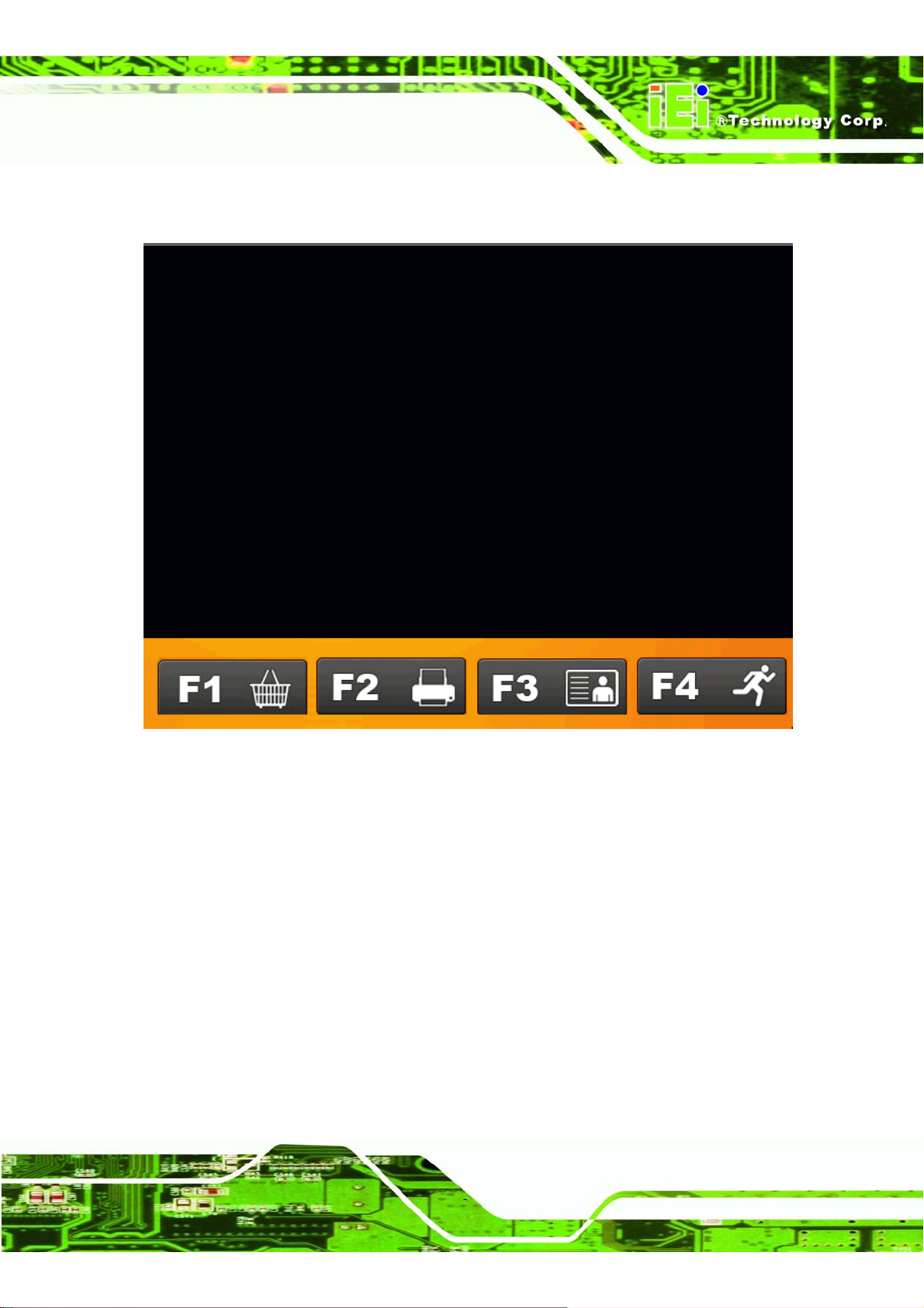
Figure 3–2: Play Video
Page 57
Page 72
IMK-571R Software and Programming Guides
3.4 Button F1: Barcode Demo.
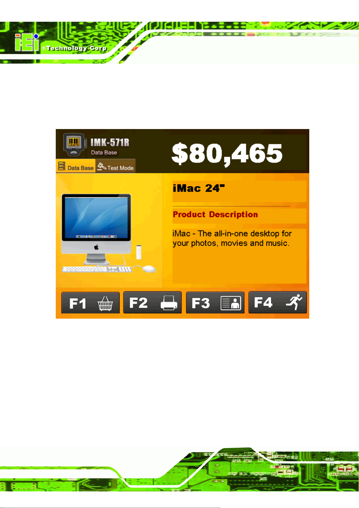
“Select” Data Base – Search barcode in data base(XML) and display in this screen.
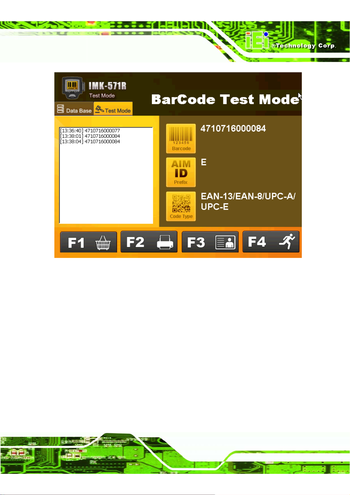
“Select” Test Mode – List barcode and compare with AIM ID data base.
Page 58
Figure 3–3: Barcode Demo
Page 73
IMK-571R Software and Programming Guides
Figure 3–4: Barcode Demo - Test Mode
Page 59
Page 74
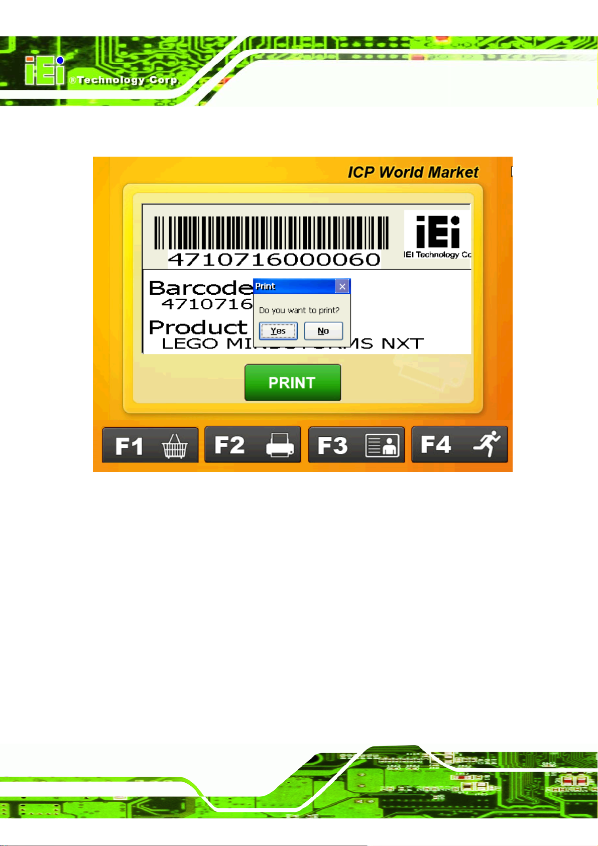
IMK-571R Software and Programming Guides
3.5 Button F2: Printer Demo
Page 60
Figure 3–5: Main Screen
Page 75
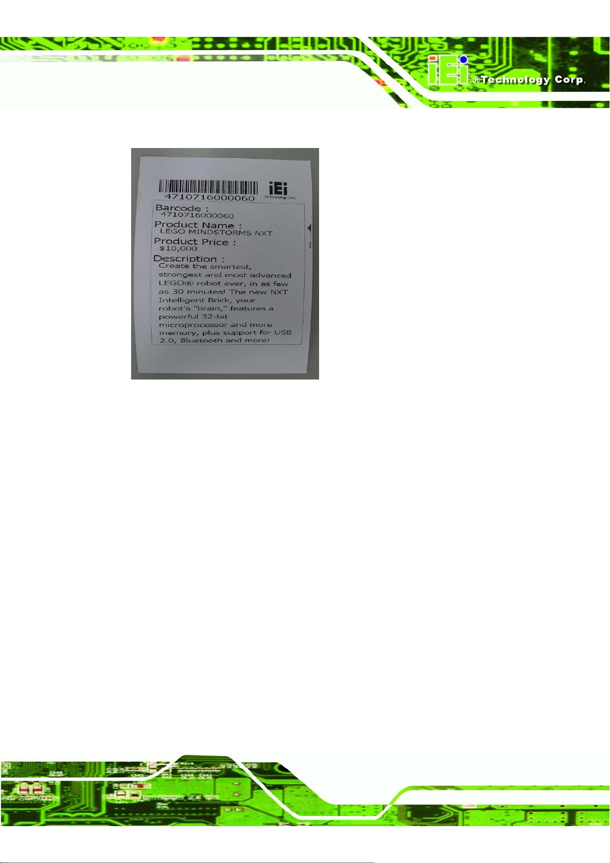
IMK-571R Software and Programming Guides
Print Result
Figure 3–6: Main Screen
Page 61
Page 76

IMK-571R Software and Programming Guides
3.6 Button F3: MSR Demo.
Page 62
Figure 3–7: MSR Demo Screen
Page 77
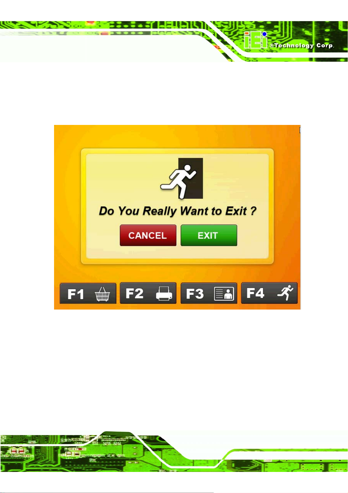
IMK-571R Software and Programming Guides
3.7 Button F4: Exit
“Select” Exit button - Exit to WinCE.
”Select” Cancel button - Go back to IMK Runtime Demo Main Frame.
Figure 3–8: Exit
Notice : If you confront trouble when compiling IMK Runtime Demo source
code, please refer to solution in Chapter 9 FAQ
Page 63
Page 78
IMK-571R Software and Programming Guides
Chapter
4
4 XML Merchandise
Manager
Page 64
Page 79
IMK-571R Software and Programming Guides
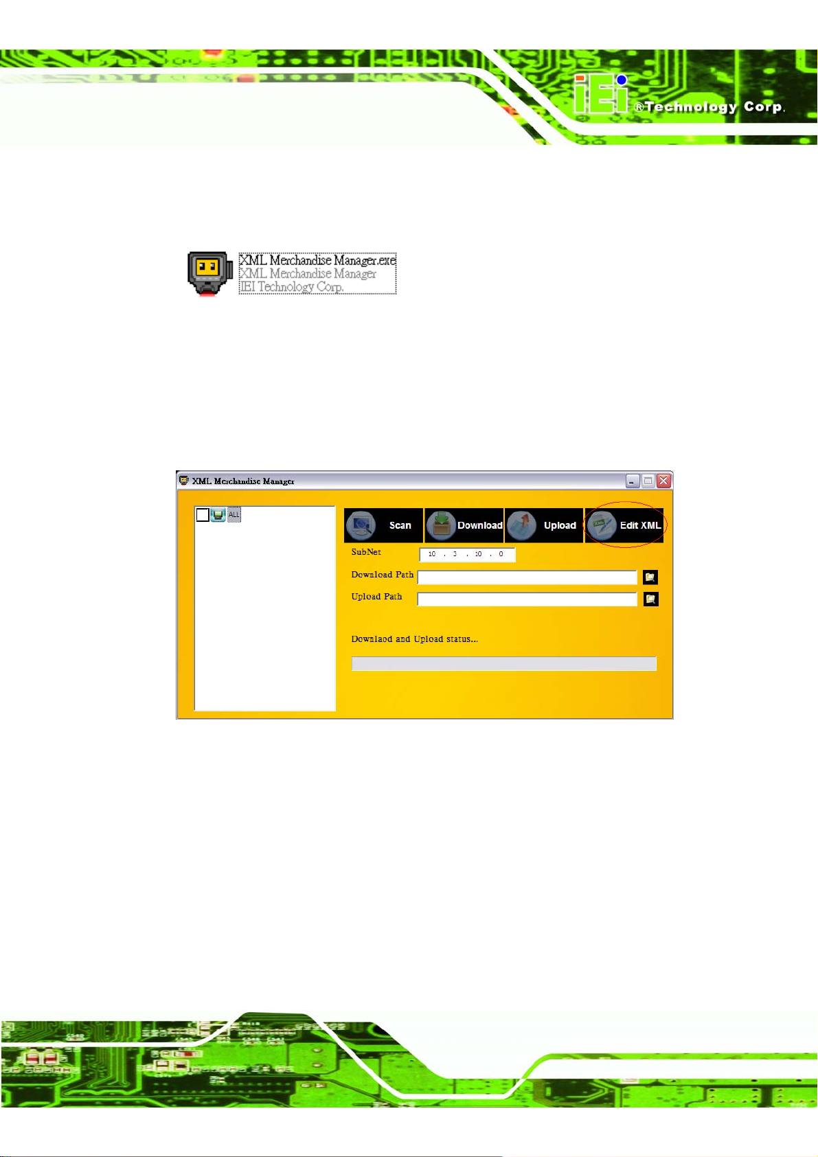
4.1 Starting the XM L Merchandise Manager
Double-click the XML Merchandise Manager.exe icon to start the program.
Figure 4–1: XML Merchandise Manager Icon
4.2 Modifying the XML File
Step 3: Click "Edit XML" to select the location of the XML file containing the product
information.
Figure 4–2: Main Window
Page 65
Page 80
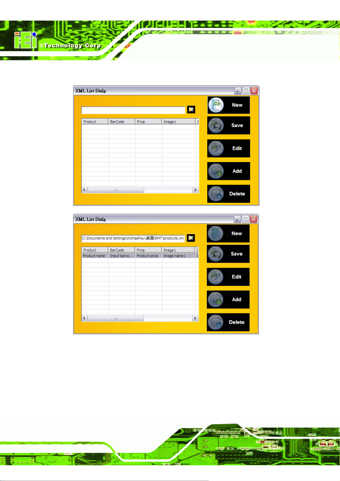
Step 4: Click the "New" button to pick the location where the XML file will be created.
IMK-571R Software and Programming Guides
Page 66
Figure 4–3: Create a New XML File
Page 81
IMK-571R Software and Programming Guides
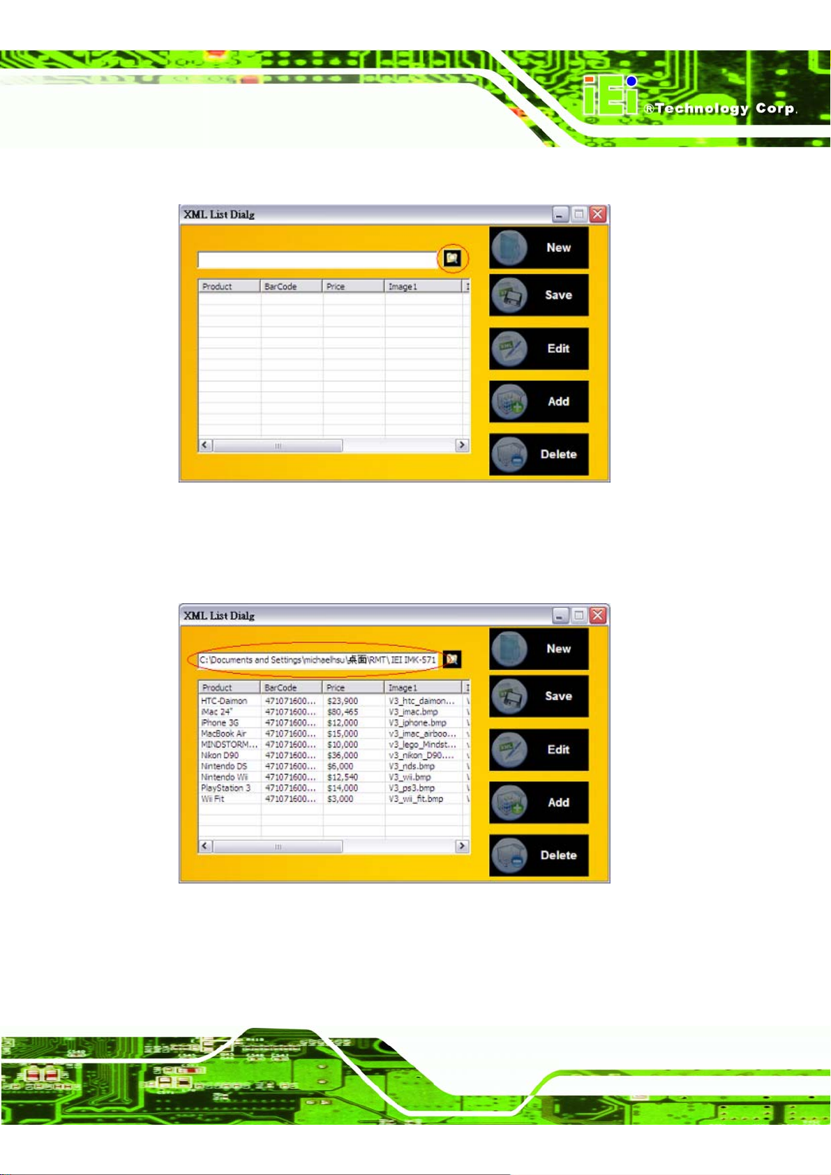
Step 5: Click the "Folder" button to pick the XML file.
Figure 4–4: XML List Dialog
Step 6: The location of the XML file is selected and the product information contained in
the file is displayed in the space below.
Figure 4–5: XML File Product List
Page 67
Page 82
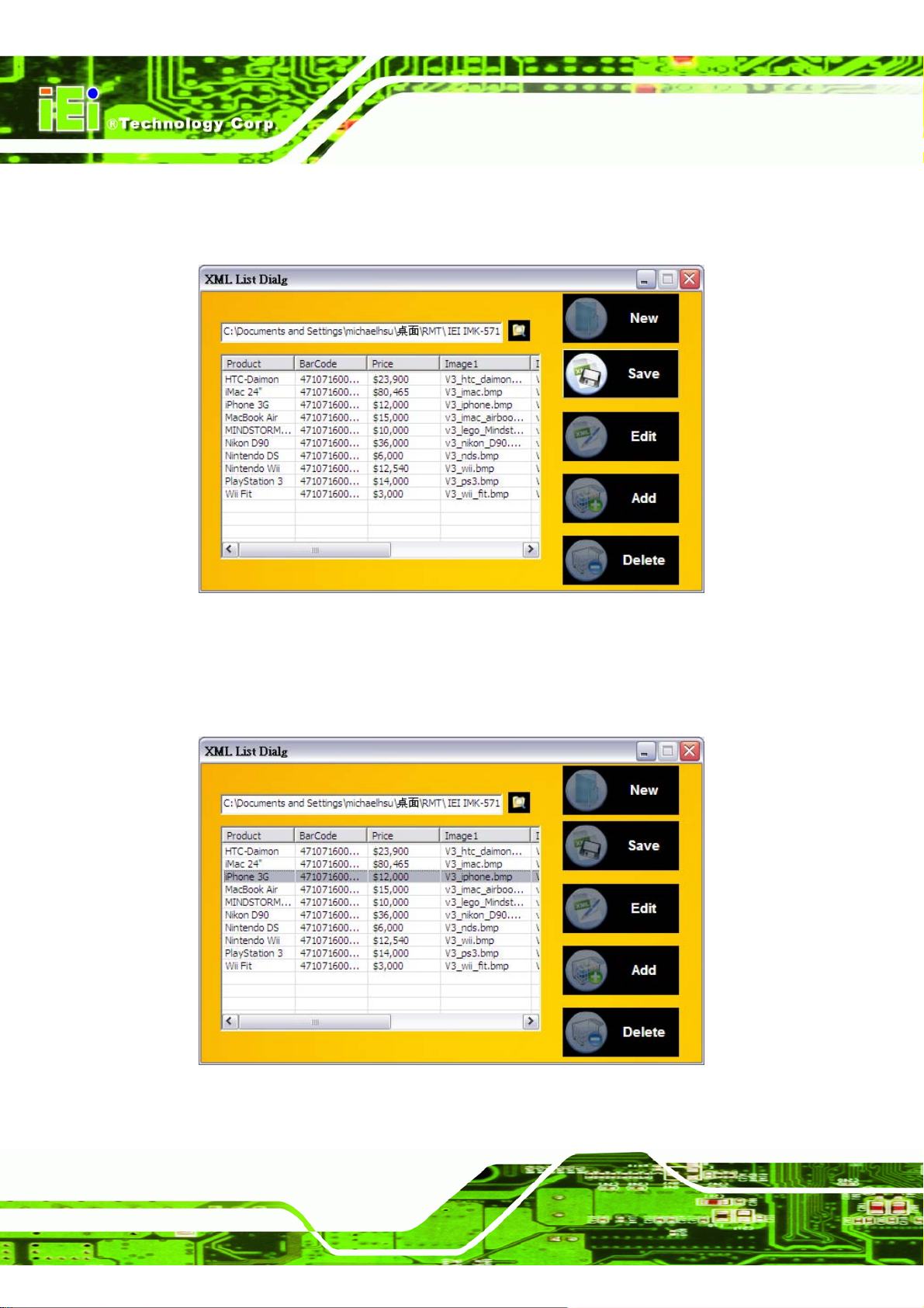
Step 7: Click Save to save any changes. These changes are only saved to the local
copy of the XML file.
IMK-571R Software and Programming Guides
Figure 4–6: Save Local XML Product File
Step 8: Double-click a product item, or selec t a product item and click "Edit" to change
the information for that item.
Page 68
Figure 4–7: Edit Product Information
Page 83
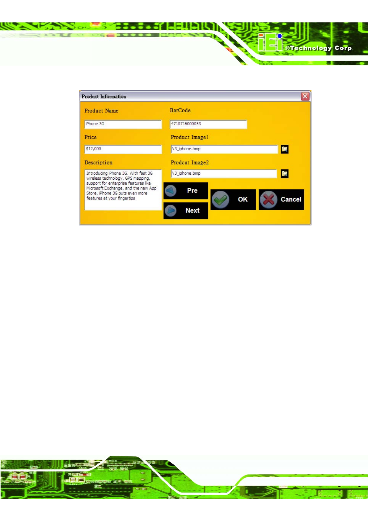
IMK-571R Software and Programming Guides
Step 9: Edit the product information in the dialog box.
Figure 4–8: Update Product Information
Page 69
Page 84
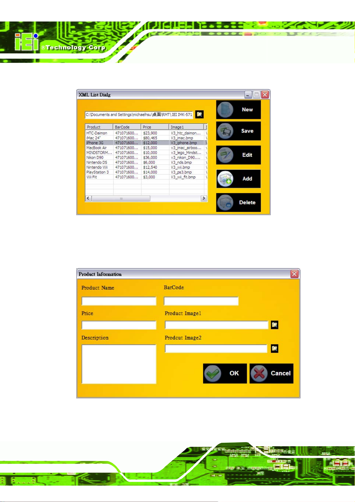
Step 10: Click the "Add" button to add new product information.
IMK-571R Software and Programming Guides
Figure 4 –9: Add New Product
Step 11:
Enter the new product informatio n an d c lic k OK to apply the s et ting s .
Page 70
Figure 4–10: Add New Product Dialog
Page 85
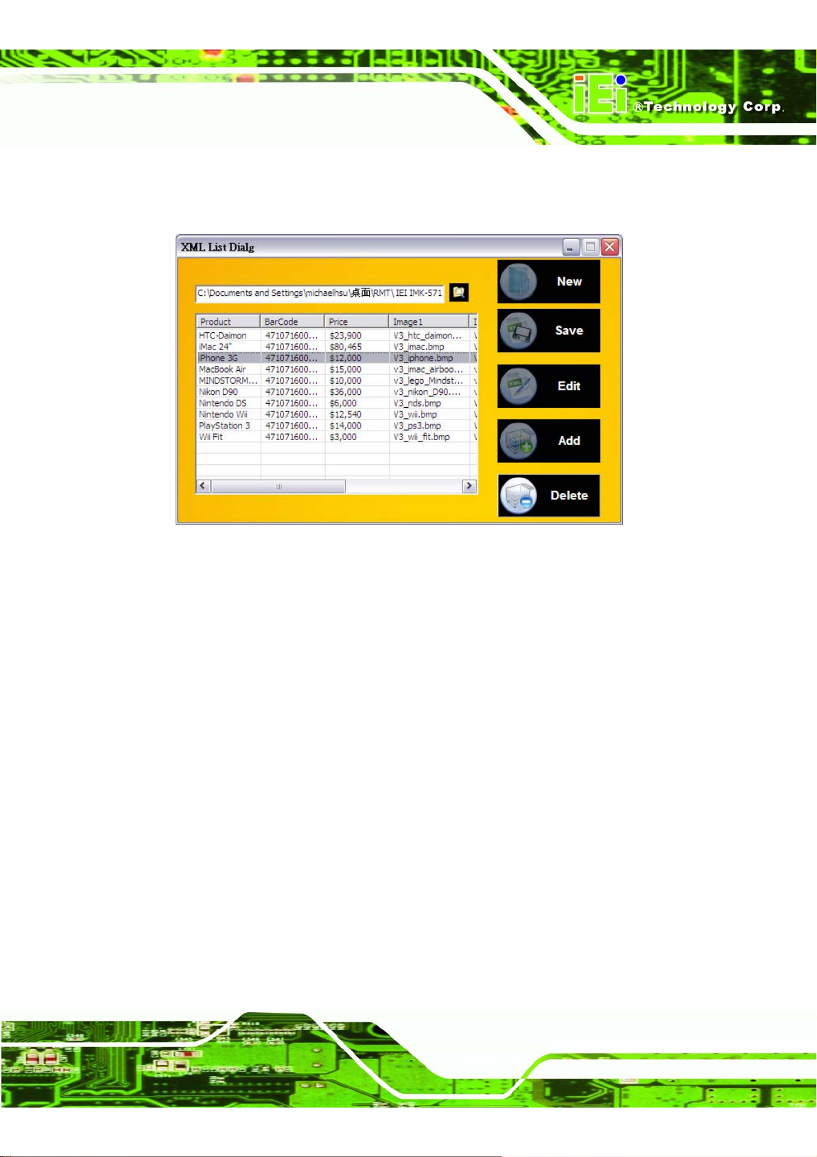
IMK-571R Software and Programming Guides
Step 12: Click Delete to delete the selected product. If no product is selected, the first
item in the list will be deleted. Step 0:
Figure 4–11: Delete Product from XML File
Page 71
Page 86
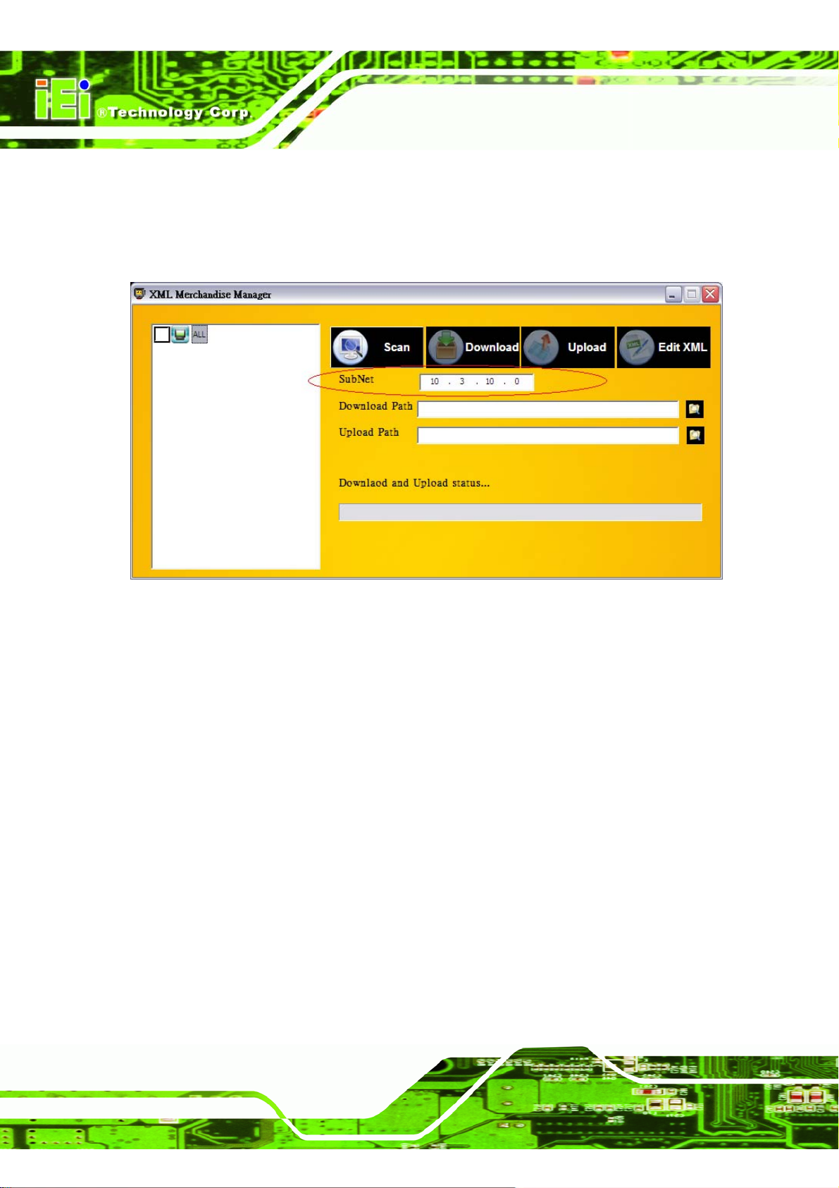
IMK-571R Software and Programming Guides
4.3 Scanning for XML Files on the Network Subnet
Step 1: The subnet is automatically selected according to the current network settings.
To select a different subnet, just change this value.
Figure 4–12: Scan Subnet
Page 72
Page 87
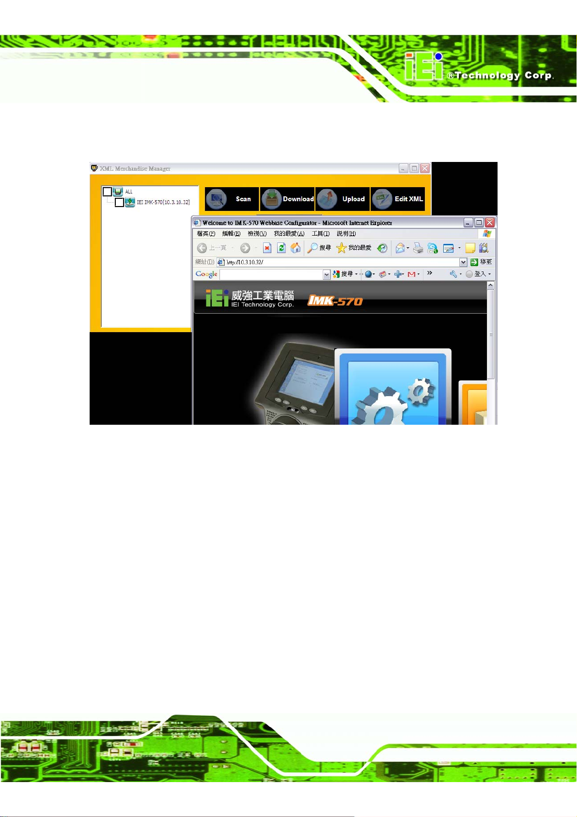
IMK-571R Software and Programming Guides
Step 2: Double-click a list itemDouble-click any list item to get a popup of the target
computer's IMK web browser-based configuration tool.Step 0:
Figure 4–13: Web Interface
Page 73
Page 88
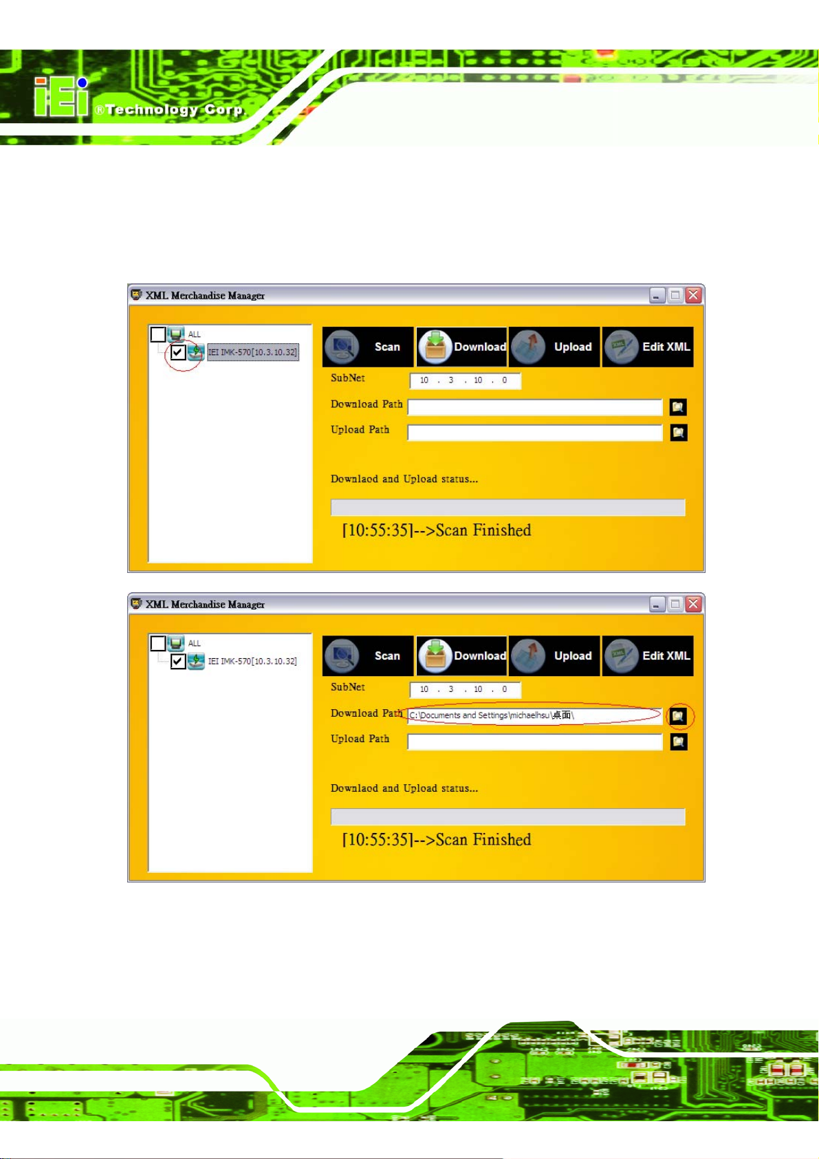
IMK-571R Software and Programming Guides
4.4 Downloading XML Files from IMK-571R
Step 1: Click the download button to start downloading the selected items.
Step 2: Select the current Download location of the XML files
Figure 4–14: Remote File List
Page 74
Page 89
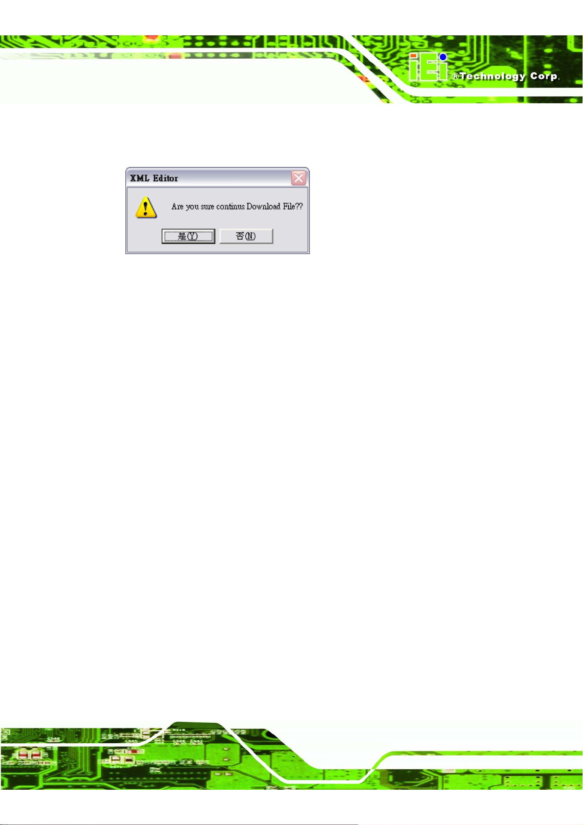
IMK-571R Software and Programming Guides
Step 3: Confirm the download of the XML files. Click Yes to download the files or No to
go back.
Figure 4–15: Download Confirmation
Page 75
Page 90
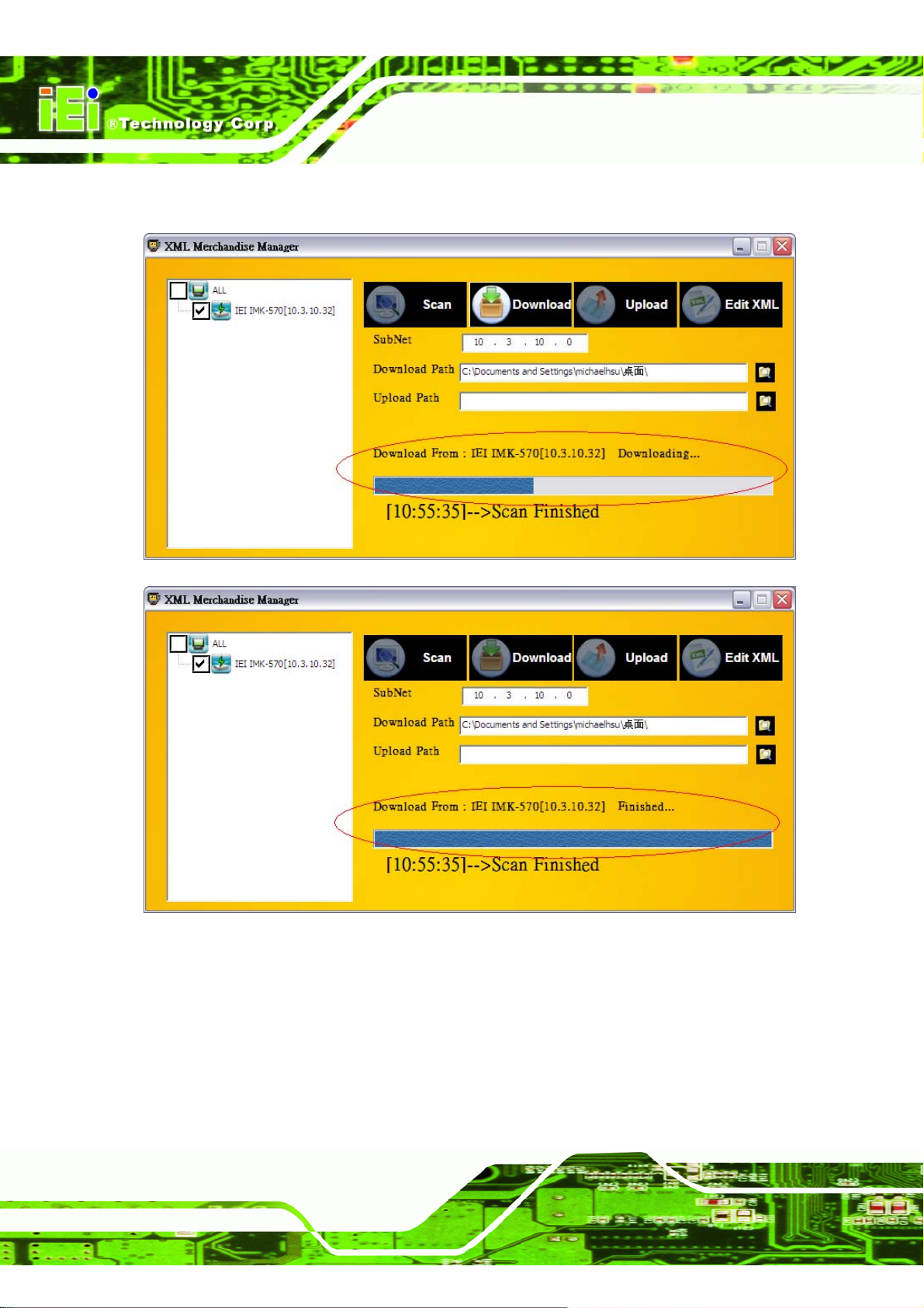
Step 4: The download progress is shown in the progress column.Step 0:
IMK-571R Software and Programming Guides
Page 76
Figure 4–16: Download Progress
Page 91
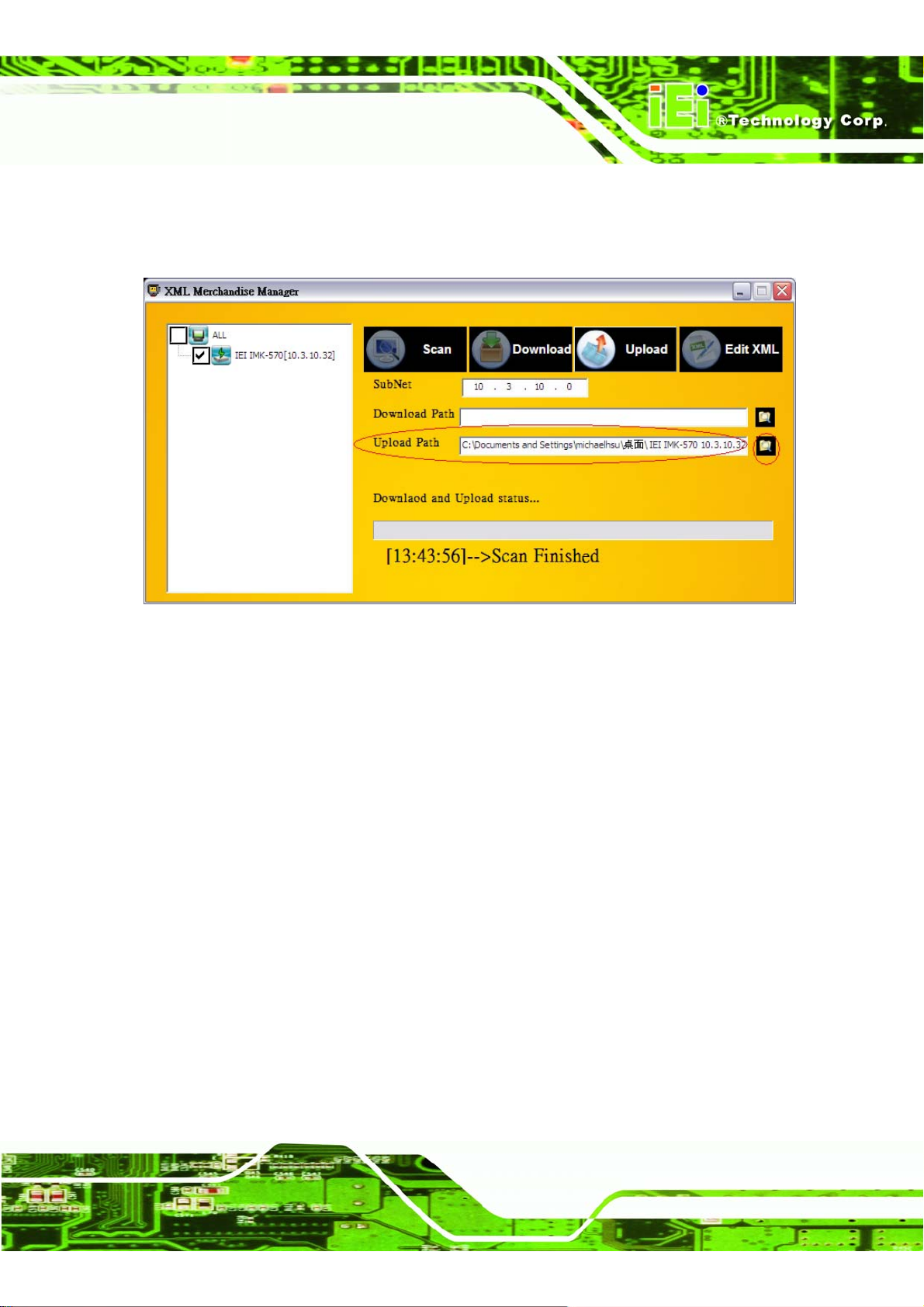
IMK-571R Software and Programming Guides
4.5 Uploading XML Files to IMK-571R
Step 1: Select the path of the XML file to upload.
Figure 4–17: Local Product File Selection
Page 77
Page 92
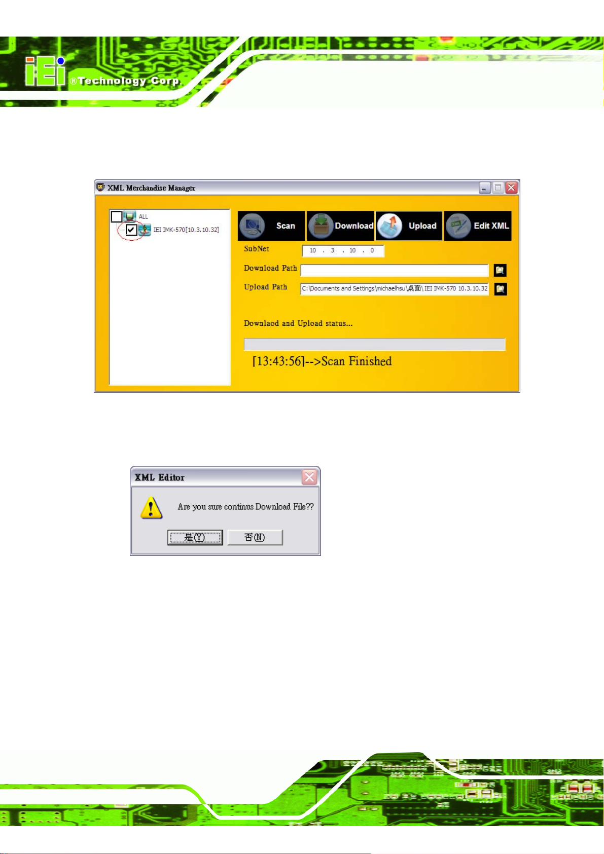
Step 2: Select the target computer to upload to.
Step 3: Click the upload button to start uploading.
IMK-571R Software and Programming Guides
Figure 4–18: Product File Upload
Step 4: Click Yes to start uploading the file or No to cancel.Step 0:
Figure 4–19: Product Upload Confirmation
Page 78
Page 93
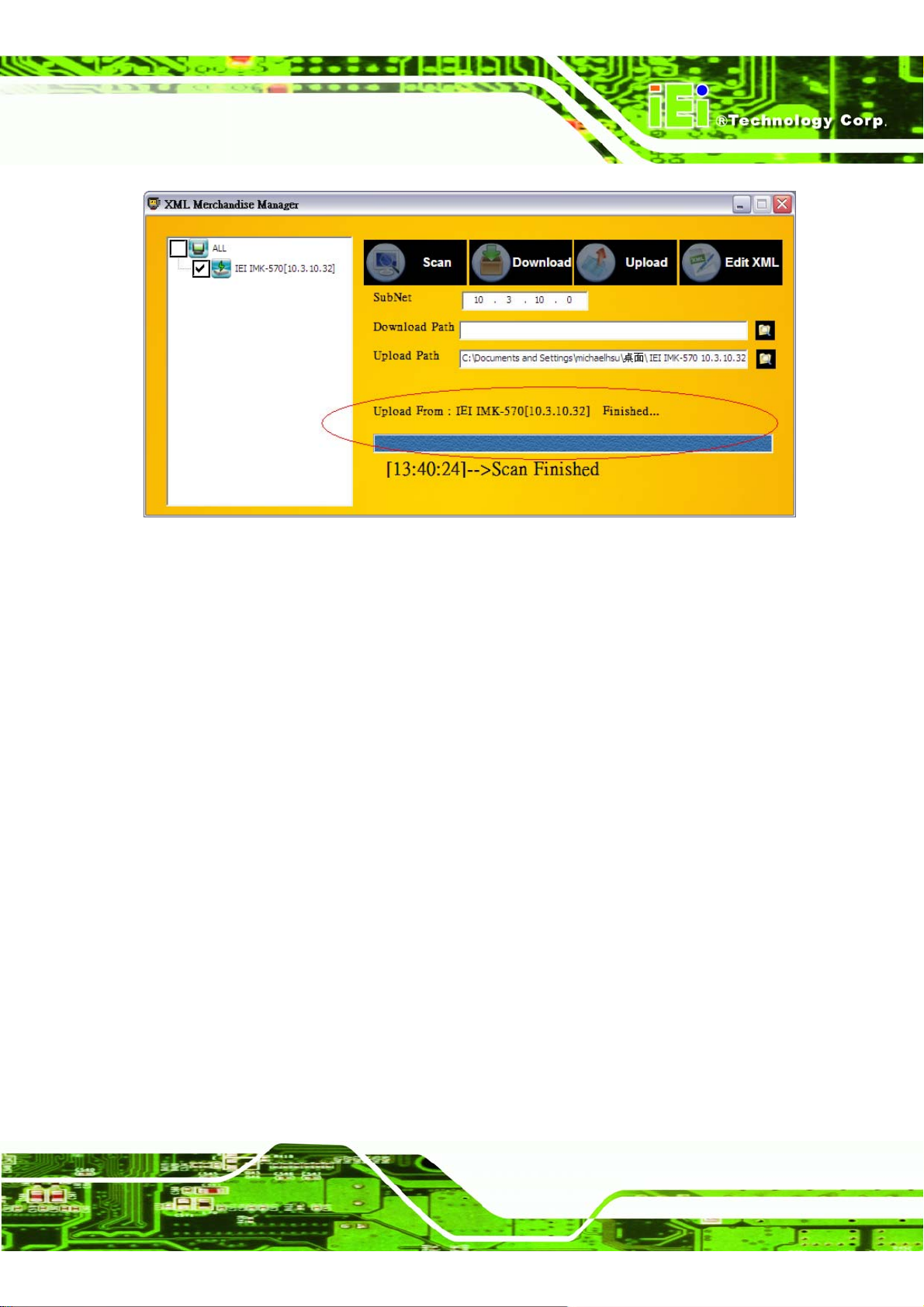
IMK-571R Software and Programming Guides
Figure 4–20: Upload Progress Bar
Page 79
Page 94
IMK-571R Software and Programming Guides
Chapter
5
5 IMK Web Interface
Page 80
Page 95
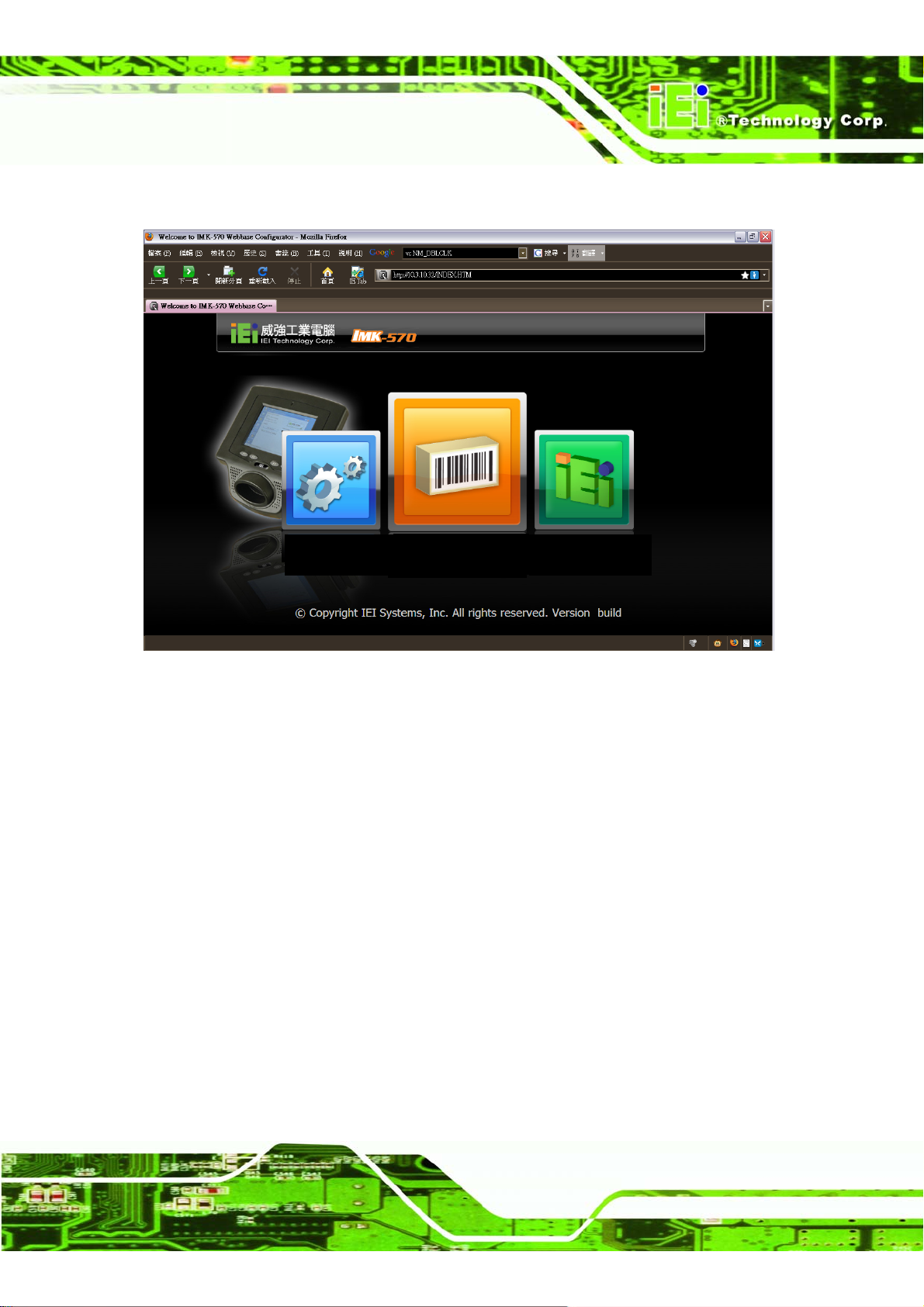
IMK-571R Software and Programming Guides
5.1 IMK Web Interface Main Page
System
Settings
Figure 5–1: Main Screen
Barcode
Settings
IEI
Website
Page 81
Page 96
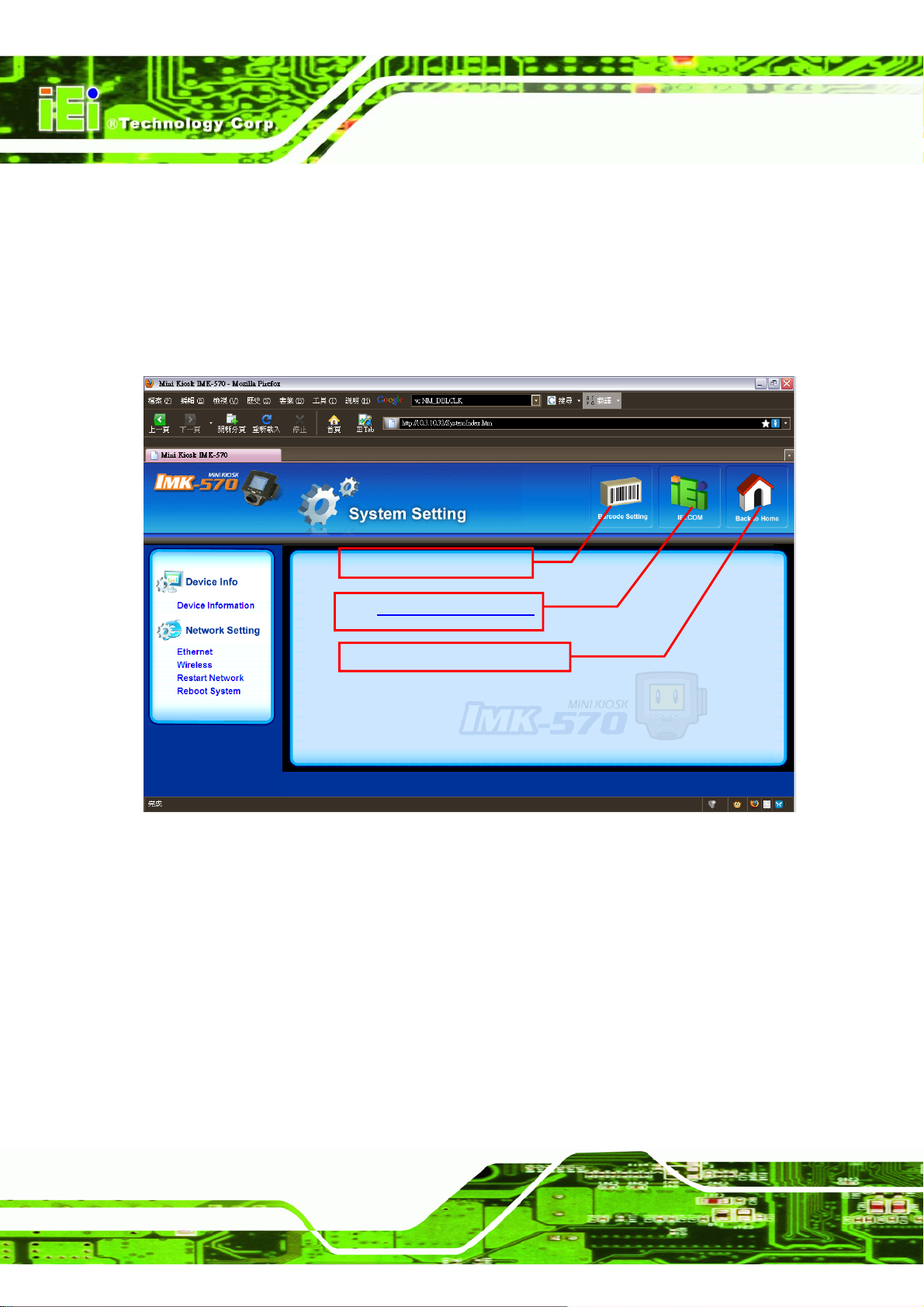
IMK-571R Software and Programming Guides
5.2 System Settings Pages
Adjust the main settings of the IMK-571R.
5.2.1 Main Page
The main system settings page.
Go to barcode settings page
Go to http://www.ieiworld.com
Return to the main settings page.
Figure 5–2: Main System Settings Page
Page 82
Page 97
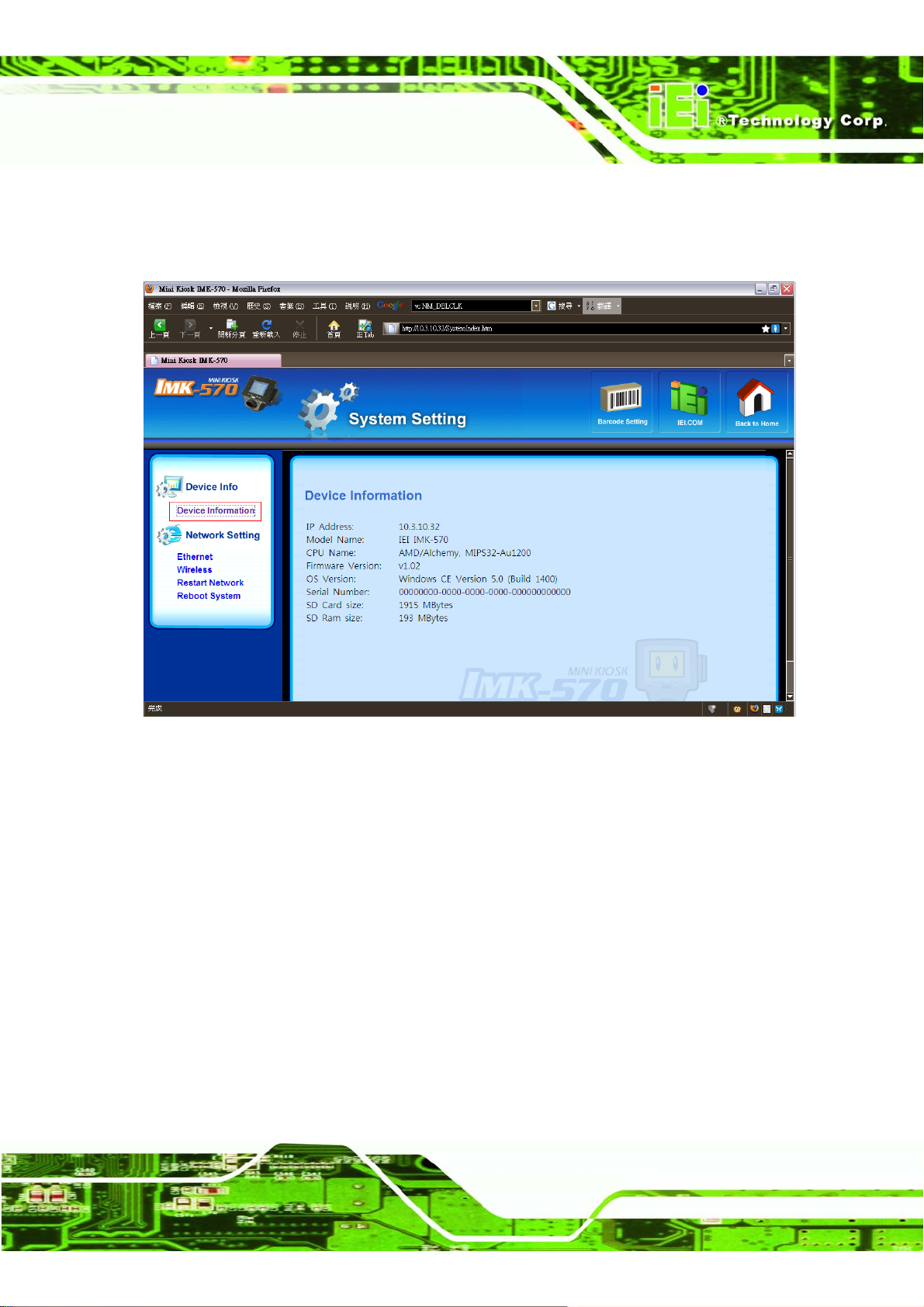
IMK-571R Software and Programming Guides
5.2.2 Device Information
Displays general system information.
Figure 5–3: Device Information (System Settings Page)
Page 83
Page 98
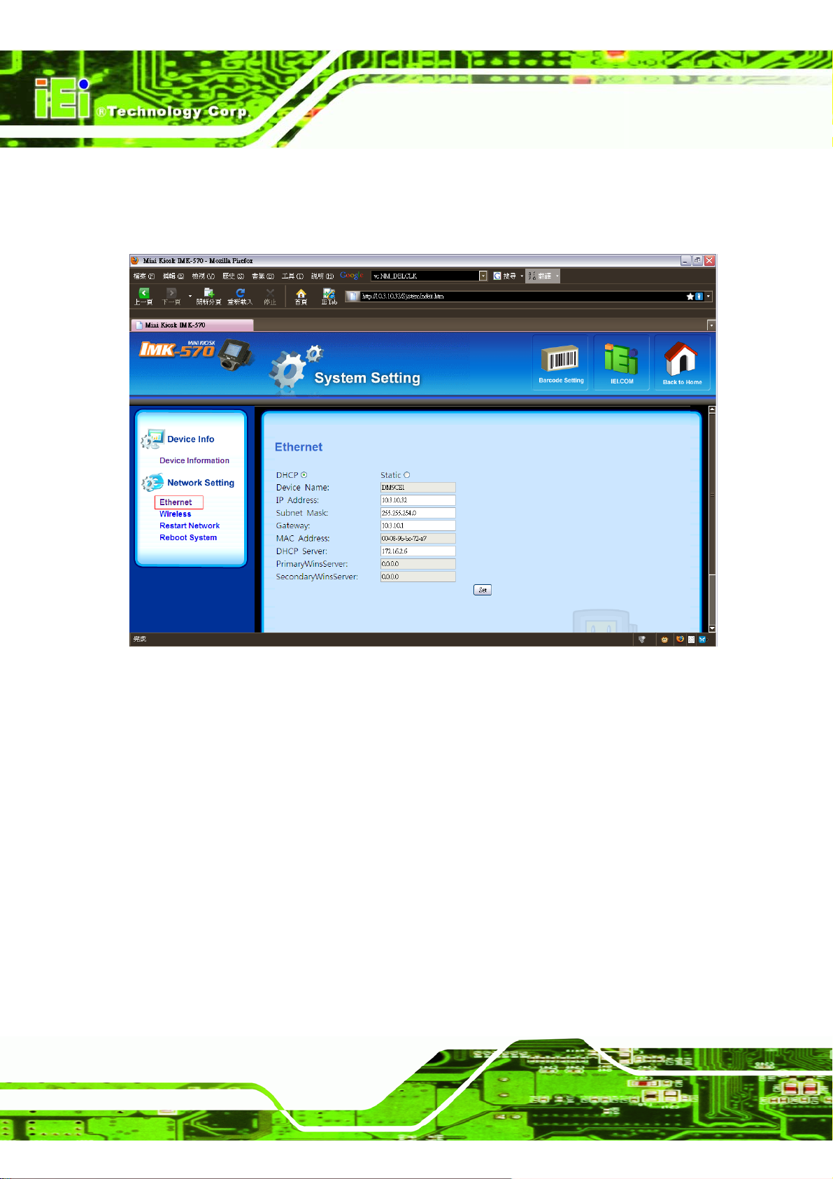
5.2.3 Ethernet
Shows Ethernet settings.
IMK-571R Software and Programming Guides
Page 84
Figure 5–4: Ethernet (System Settings Page)
Page 99
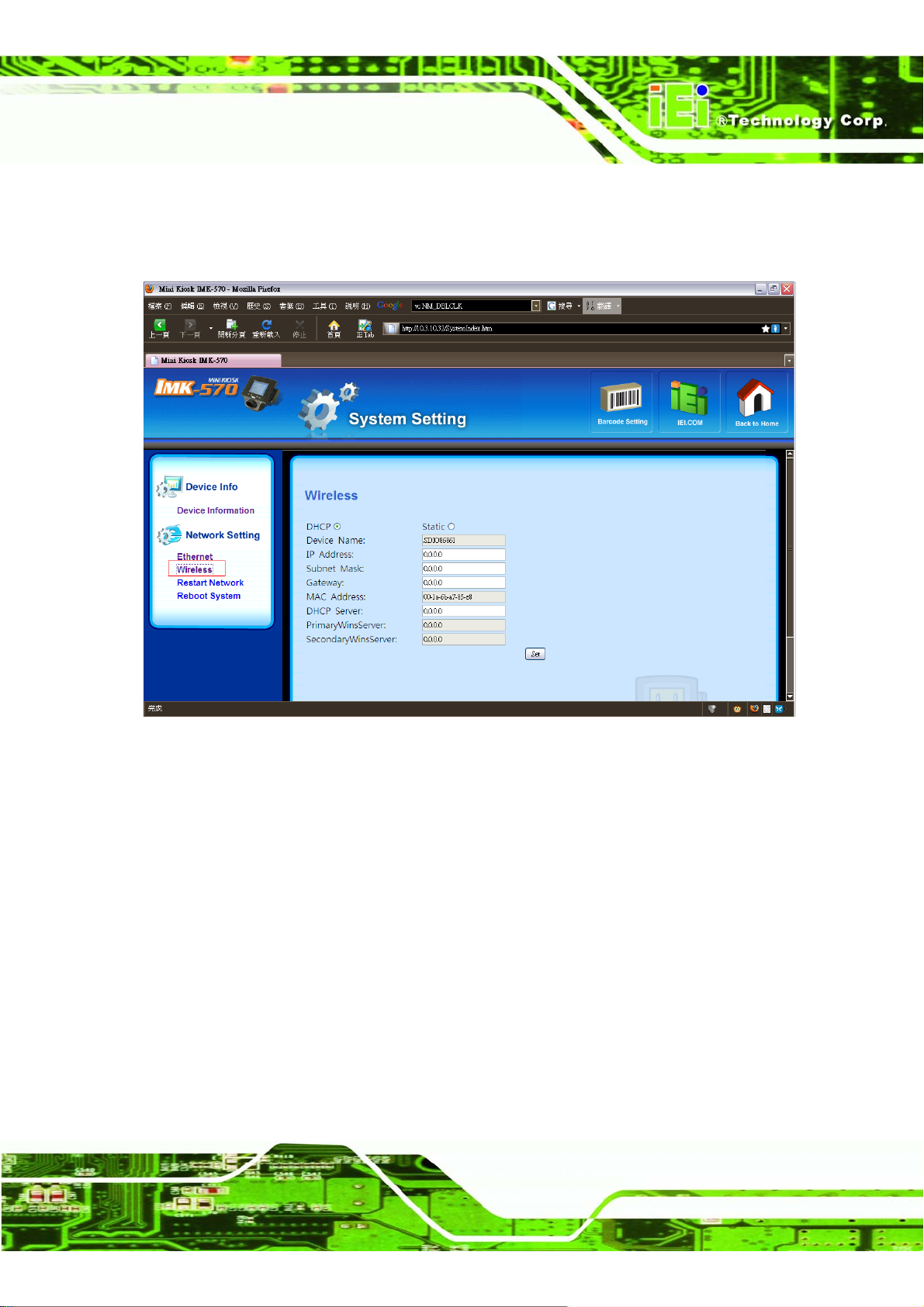
IMK-571R Software and Programming Guides
5.2.4 Wireless
Show the target device’s Wireless information.
Figure 5–5: Wireless (System Settings Page)
Page 85
Page 100
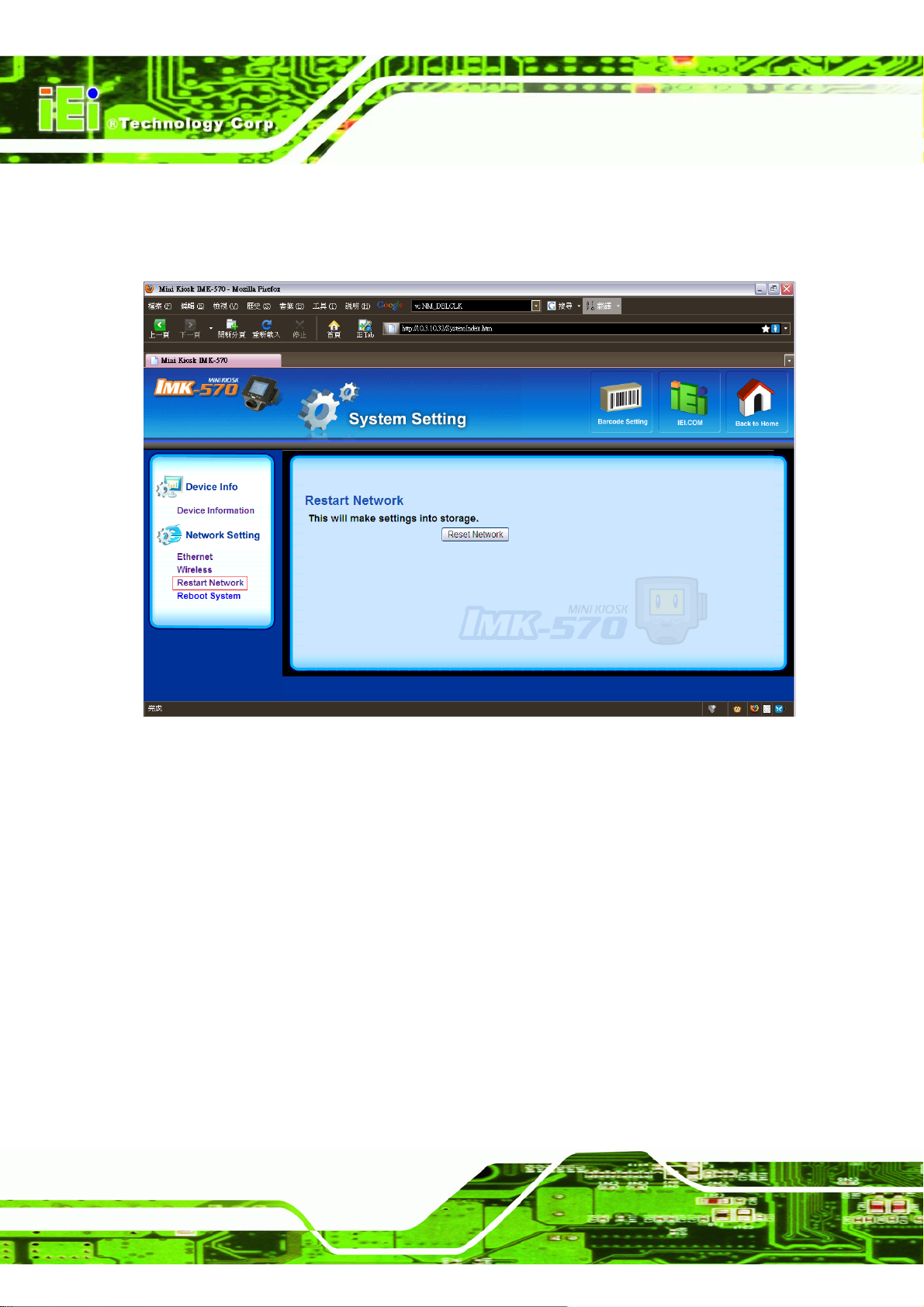
5.2.5 Restart Network
Reset the network connection on the connected IMK-571R.
IMK-571R Software and Programming Guides
Page 86
Figure 5–6: Restart Network (System Settings Page)
 Loading...