

Page 1
HYPER-RK39 SBC
Page I
HYPER-RK39
MODEL:
Pico-ITX SBC with Rockchip RK3399 Processor,
Rev. 1.00 - September 14, 2018
HYPER-RK39 CPU Card
2 GB LPDDR3, 16 GB eMMC Flash, HDMI, eDP, GbE LAN,
PCIe Mini, USB 3.1, USB 2.0, COM and RoHS
User Manual
Page 2
HYPER-RK39 SBC
Page II
Date Version Changes
September 14, 2018 1.00 Initial release
Revision
Page 3

HYPER-RK39 SBC
Page III
Copyright
COPYRIGHT NOTICE
The information in this document is subject to change without prior notice in order to
improve reliability, design and function and does not represent a commitment on the part
of the manufacturer.
In no event will the manufacturer be liable for direct, indirect, special, incidental, or
consequential damages arising out of the use or inability to use the product or
documentation, even if advised of the possibil ity of such damages.
This document contains proprietary information protected by copyright. All rights are
reserved. No part of this manual may be reproduced by any mechanical, electronic, or
other means in any form without prior written permission of the manufacturer.
TRADEMARKS
All registered trademarks and product names mentioned herein are used for identification
purposes only and may be trademarks and/or registered trademarks of their respective
owners.
Page 4
HYPER-RK39 SBC
Page IV
Manual Conventions
WARNING
Warnings appear where overlooked details may cause damage to the
equipment or result in personal injury. Warnings should be taken
seriously.
CAUTION
Cautionary messages should be heeded to help red uce the chance of
losing data or damaging the product.
NOTE
These messages inform the reader of essent ial but non-critical
information. These messages should be read carefully as any directions
or instructions contained therein can help avoid making mistakes.
Page 5

HYPER-RK39 SBC
Page V
Table of C ont ents
1 INTRODUCTION .......................................................................................................... 1
1.1 INTRODUCTION ........................................................................................................... 2
1.2 FEATURES ................................................................................................................... 3
1.3 CONNECTORS ............................................................................................................. 4
1.4 DIMENSIONS ............................................................................................................... 5
1.5 DATA FLOW ................................................................................................................ 6
1.6 TECHNICAL SPECIFICATIONS ...................................................................................... 7
2 UNPACKING ................................................................................................................. 9
2.1 ANTI-STATIC PRECAUTIONS ...................................................................................... 10
2.2 UNPACKING PRECAUTIONS ....................................................................................... 10
2.3 PACKING LIST ............................................................................................................ 11
2.4 OPTIONAL ITEMS ...................................................................................................... 12
3 CONNECTORS ........................................................................................................... 14
3.1 PERIPHERAL INTERFACE CONNECTORS ..................................................................... 15
3.1.1 HYPER-RK39 Layout ....................................................................................... 15
3.1.2 Peripheral Interface Connectors ..................................................................... 16
3.1.3 External Interface Panel Connectors ............................................................... 17
3.2 INTERNAL PERIPHERAL CONNECTORS ...................................................................... 17
3.2.1 Antenna Connectors ......................................................................................... 17
3.2.2 Battery Connector ............................................................................................ 18
3.2.1 Camera Connector ........................................................................................... 19
3.2.1 Debug Port ....................................................................................................... 20
3.2.1 Earphone Connector ........................................................................................ 21
3.2.1 eDP Connector ................................................................................................. 22
3.2.2 General Purpose I/O Connector ...................................................................... 23
3.2.1 microSD Slot .................................................................................................... 24
3.2.1 PCIe Mini Card Slot ........................................................................................ 24
3.2.2 Power Connector ............................................................................................. 26
3.2.1 Power Button Connector .................................................................................. 27
Page 6

HYPER-RK39 SBC
Page VI
3.2.2 Power Key Connector ...................................................................................... 28
3.2.1 Reset Button ..................................................................................................... 28
3.2.1 Speaker Connector ........................................................................................... 29
3.3 EXTERNAL PERIPHERAL INTERFACE CONNECTOR PANEL ......................................... 30
3.3.1 HDMI Connector ............................................................................................. 30
3.3.2 LAN Connector ................................................................................................ 31
3.3.1 RS-232/422/485 Serial Port Connector (COM1) ............................................ 32
3.3.2 USB Connectors ............................................................................................... 33
4 INSTALLATION ......................................................................................................... 35
4.1 ANTI-STATIC PRECAUTIONS ...................................................................................... 36
4.2 INSTALLATION CONSIDERATIONS .............................................................................. 36
4.3 FULL-SIZE PCIE MINI CARD INSTALLATION ............................................................. 38
4.4 CHASSIS INSTALLATION ............................................................................................ 40
4.4.1 Airflow .............................................................................................................. 40
4.4.2 Heat Sink Installation ...................................................................................... 40
4.4.3 Motherboard Installation ................................................................................. 41
4.5 AVAILABLE DRIVERS ................................................................................................ 42
4.5.1 Driver Download ............................................................................................. 42
5 ANDROID OS .............................................................................................................. 44
5.1 HOME SCREEN ......................................................................................................... 45
5.1.1 Adding a Home Screen ..................................................................................... 45
5.1.2 Switching between Home Screens .................................................................... 46
5.1.3 Favorites Tray .................................................................................................. 46
5.1.4 Adding Shortcuts .............................................................................................. 47
5.1.5 Arranging the Home Screen ............................................................................. 49
5.2 NAVIGATION BUTTONS ............................................................................................. 50
5.3 STATUS BAR ............................................................................................................. 51
6 UBUNTU OS ................................................................................................................ 53
6.1 DESKTOP .................................................................................................................. 54
6.2 MENU ....................................................................................................................... 55
6.3 NETWORK CONNECTION .......................................................................................... 56
6.4 MANAGING APPLICATIONS ....................................................................................... 57
Page 7

HYPER-RK39 SBC
Page VII
A REGULATORY COMPLI AN CE .............................................................................. 59
B PRODUCT DISPOSAL .............................................................................................. 61
C HAZARDOUS MATERIALS DISCLOSURE ......................................................... 63
Page 8

HYPER-RK39 SBC
Page VIII
List of Figures
Figure 1-1: HYPER-RK39 ............................................................................................................... 2
Figure 1-2: Connectors (Front Side) ............................................................................................. 4
Figure 1-3: Connectors (Solder Side) ........................................................................................... 4
Figure 1-4: Dimensions (mm) ........................................................................................................ 5
Figure 1-5: Data Flow Diagram ...................................................................................................... 6
Figure 3-1: Connector and Jumper Locations (Front Side) ..................................................... 15
Figure 3-2: Connector and Jumper Locations (Solder Side) ................................................... 15
Figure 3-3: Antenna Connector Location ................................................................................... 17
Figure 3-4: Battery Connector Location ..................................................................................... 18
Figure 3-5: Camera Connector Location .................................................................................... 19
Figure 3-6: Debug Port Location ................................................................................................. 20
Figure 3-7: Earphone Connector Location ................................................................................ 21
Figure 3-8: eDP Connector Location .......................................................................................... 22
Figure 3-9: General Purpose Connector Locations .................................................................. 23
Figure 3-10: microSD Slot Location ............................................................................................ 24
Figure 3-11: PCIe Mini Card Slot Location ................................................................................. 24
Figure 3-12: Power Connector Location .................................................................................... 26
Figure 3-13: Power Button Connector Location ........................................................................ 27
Figure 3-14: Power Key Connector Location ............................................................................. 28
Figure 3-15: Reset Button Location ............................................................................................ 29
Figure 3-16: Speaker Connector Pinouts ................................................................................... 29
Figure 3-17: External Peripheral Interface Conn ector .............................................................. 30
Figure 3-18: HDMI Connector ...................................................................................................... 31
Figure 3-19: LAN Connector ........................................................................................................ 32
Figure 3-20: Serial Port Pinouts .................................................................................................. 33
Figure 3-21: External USB Type-A Ports .................................................................................... 33
Figure 3-22: External USB 3.1 Type-C Port ................................................................................ 34
Figure 4-1: Removing the Retention Screw ............................................................................... 38
Figure 4-2: Inserting the Full-size PCIe Mini Card into the Slot at an Angle .......................... 39
Figure 4-3: Securing the Full-size PCIe Mini Card .................................................................... 39
Figure 4-4: Heat Sink Installation ................................................................................................ 41
Page 9

HYPER-RK39 SBC
Page IX
Figure 4-5: IEI Resource Download Center ................................................................................ 42
Figure 4-1: Adding a Home Screen ............................................................................................. 45
Figure 4-2: Multiple Home Screens ............................................................................................. 46
Figure 4-3: Favorites Tray ............................................................................................................ 46
Figure 4-4: All Apps/WIDGETS Page .......................................................................................... 48
Figure 4-5: Trash an Item on Home Screen ............................................................................... 49
Figure 4-6: Navigation Buttons ................................................................................................... 50
Figure 4-7: Status Bar .................................................................................................................. 51
Figure 4-8: Notification List and System Status ........................................................................ 52
Figure 4-1: Ubuntu Desktop ........................................................................................................ 54
Figure 4-2: Ubuntu Menu ............................................................................................................. 55
Figure 4-3: Ubuntu NetworkManager .......................................................................................... 56
Figure 4-4: Ubuntu Software ....................................................................................................... 57
Figure 4-5: Removing Software ................................................................................................... 58
Page 10

HYPER-RK39 SBC
Page X
List of Tables
Table 1-1: Technical Specifications .............................................................................................. 8
Table 3-1: Peripheral Interface Connectors ............................................................................... 16
Table 3-2: Rear Panel Connectors .............................................................................................. 17
Table 3-3: Battery Connector Pinouts ........................................................................................ 19
Table 3-4: Camera Connector Pinouts ....................................................................................... 20
Table 3-5: Debug Port Pinouts .................................................................................................... 20
Table 3-6: Earphone Connector Pinouts .................................................................................... 21
Table 3-7: eDP Connector Pinouts .............................................................................................. 22
Table 3-8: General Purpose Connector (CN11) Pinouts ........................................................... 23
Table 3-9: General Purpose Connector (CN16) Pinouts ........................................................... 23
Table 3-10: PCIe Mini Card Slot Pinouts .................................................................................... 25
Table 3-11: Power Connector Pinouts ........................................................................................ 26
Table 3-12: Power Button Connector Pinouts ........................................................................... 27
Table 3-13: Power Key Connector Pinouts ................................................................................ 28
Table 3-14: Speaker Connector Pinouts .................................................................................... 29
Table 3-15: HDMI Connector Pinouts ......................................................................................... 31
Table 3-16: LAN Pinouts .............................................................................................................. 31
Table 3-17: COM1 Pinouts ........................................................................................................... 32
Table 4-1: Navigation Buttons ..................................................................................................... 50
Page 11

HYPER-RK39 SBC
Page 1
Chapter
1
1 Introduction
Page 12

HYPER-RK39 SBC
Page 2
1.1 Introduction
Figure 1-1: HYPER-RK39
The HYPER-RK39 series is a single bard computer in Pico-ITX form factor with an
on-board Rockchip RK3399 SoC and 1866 MHz 2 GB LPDDR3 memory. It is a platform
that supports Android 7.1 and Ubuntu 16.04 OS.
The HYPER-RK39 series includes one HDMI connector and one eDP connector for
display. One RJ-45 GbE connector provides the system with smooth connections to an
external LAN.
Expansion and I/O include one full-size PCIe Mini slot, one USB 3.1 Type-C port, one
USB 3.1 port, one USB 2.0 port and digital I/O pin headers. Serial device connectivity is
provided by the external RS-232/422/485 connector.
Page 13

HYPER-RK39 SBC
Page 3
1.2 Features
Some of the HYPER-RK39 motherboard features are listed below:
Pico-ITX motherboard supports Rockchip RK3399 on-boa rd SoC
HDMI and eDP support dual display
On-board 1866 MHz 2 GB LPDDR3 memory
16 GB eMMC NAND flash and one microSD slot
802.11a/b/g/n/ac Wi-Fi and Bluetooth v4.1
GbE LAN supported by Realtek RTL8211E controller
Optional WWAN by t he full-size PCIe Mini slot
Equipped MIPI CSI interface for camera
One external RS-232/422/485 connector
Two USB 3.1 ports (Type-A + Type-C) and one USB 2.0 port
Support Android 7.1 and Ubuntu 16.04 OS
Page 14

HYPER-RK39 SBC
Page 4
1.3 Connectors
The connectors on the HYPER-RK39 are shown in the figure below.
Figure 1-2: Connectors (Front Side)
Figure 1-3: Connectors (Solder Side)
Page 15
HYPER-RK39 SBC
Page 5
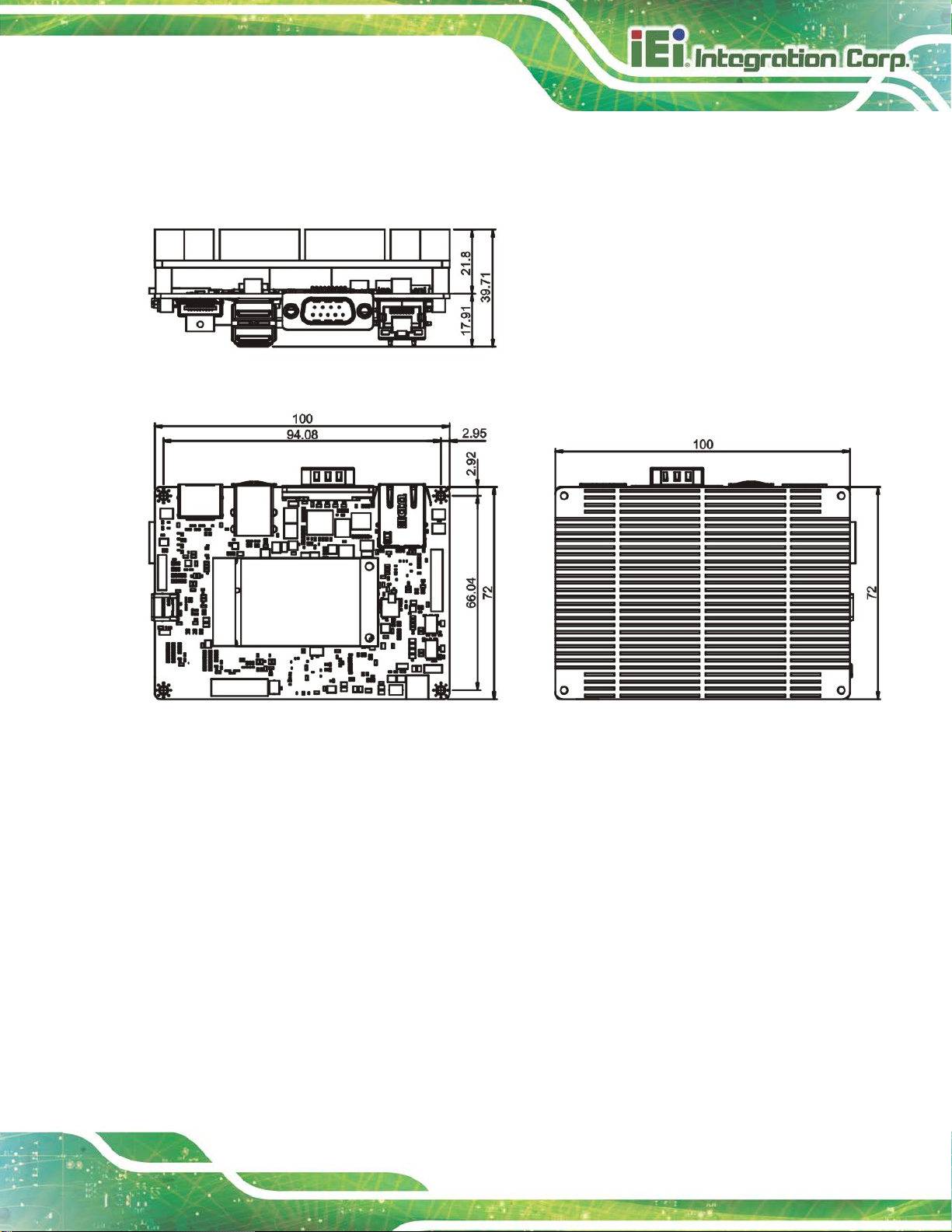
1.4 Dimensions
The dimensions of the HYPER-RK39 series are listed in Figure 1-4.
Figure 1-4: Dimensions (mm)
Page 16
HYPER-RK39 SBC
Page 6
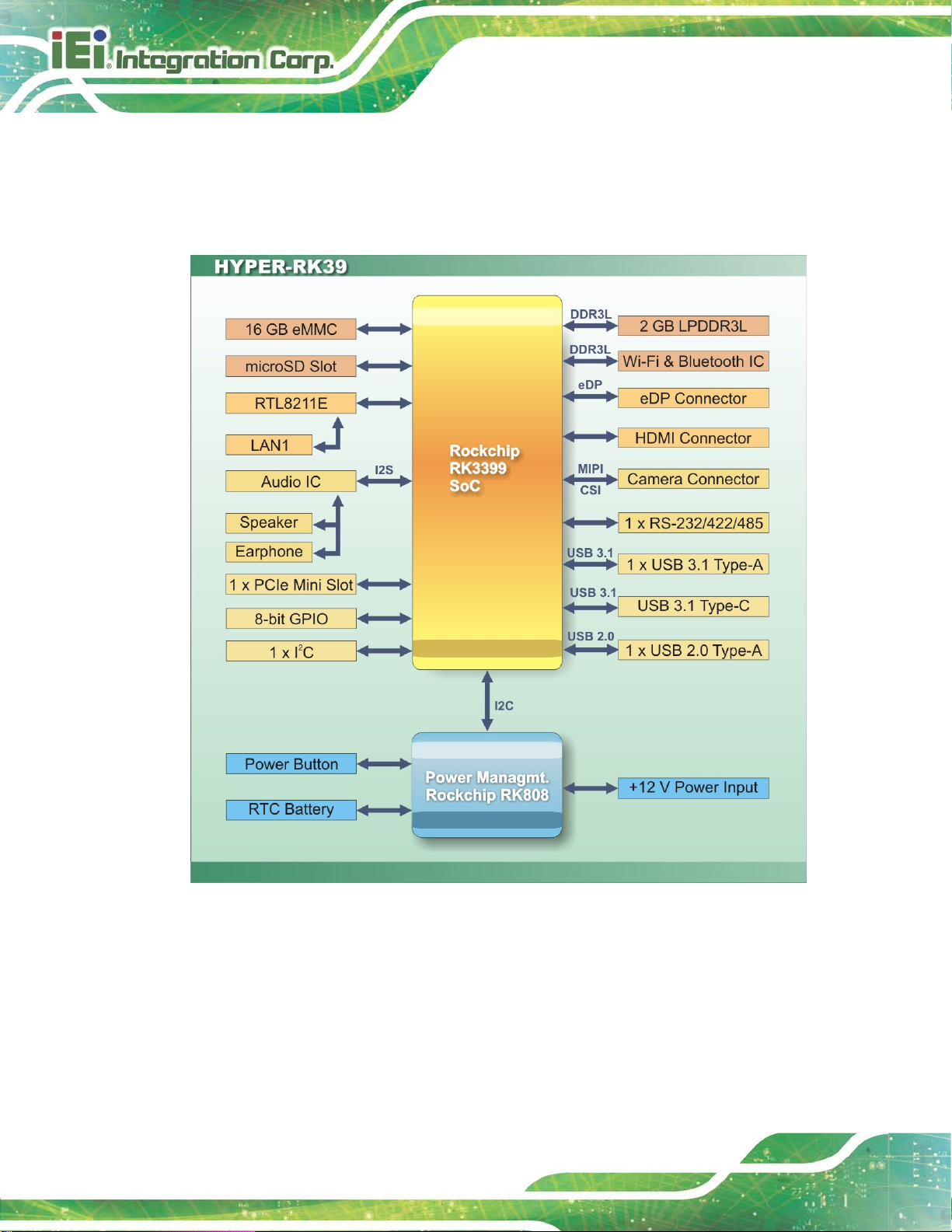
1.5 Data Flow
Figure 1-5 shows the data flow between the system chipset, the CPU and other
components installed on the motherboard.
Figure 1-5: Data Flow Diagram
Page 17
HYPER-RK39 SBC
Page 7
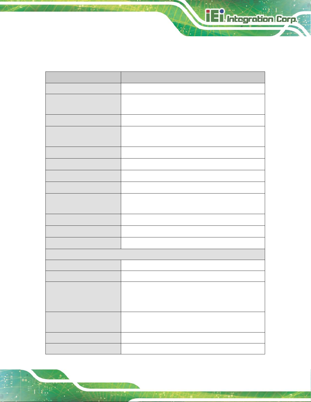
1.6 Technical Specifications
HYPER-RK39 technical specifications are listed below.
Specification HYPER-RK39
Form Factor Pico-ITX
SoC Rockchip RK3399 on-board SoC
(dual-core Cortex-A72 + quad-core Cortex-A53, 64-bit)
Memory 2 GB 1866 MHz LPDDR3L on-board memory
Storage 1 x microSD card slot
16 GB eMMC NAND flash
Wireless LAN 802.11a/b/g/n/ac
Bluetooth Bluetooth v4.1
Ethernet Realtek RTL8211E GbE transceiver
WWAN Optional by PCIe Mini LTE module
Display Output 1 x HDMI output port
1 x eDP port
Digital I/O 8-bit digital I/O (4 in and 4 out)
Supported OS Android 7.1 or Linux Ubuntu 16.04
Watchdog Timer Yes
I/O Interface
Serial Port 1 x RS-232/422/485 by DB-9
Ethernet 1 x RJ-45 GbE port
USB Ports 1 x USB 3.1 Type-A
1 x USB 3.1 Type-C (for OS update)
1 x USB 2.0 Type-A
Audio Connector 1 x Speaker connector by 2-pin header
Camera 1 x Camera connector (MIPI CSI)
I2C 1 x I2C
1 x Earphone (Line-in/line-out) connector by 10-pin wafer
Page 18
HYPER-RK39 SBC
Page 8
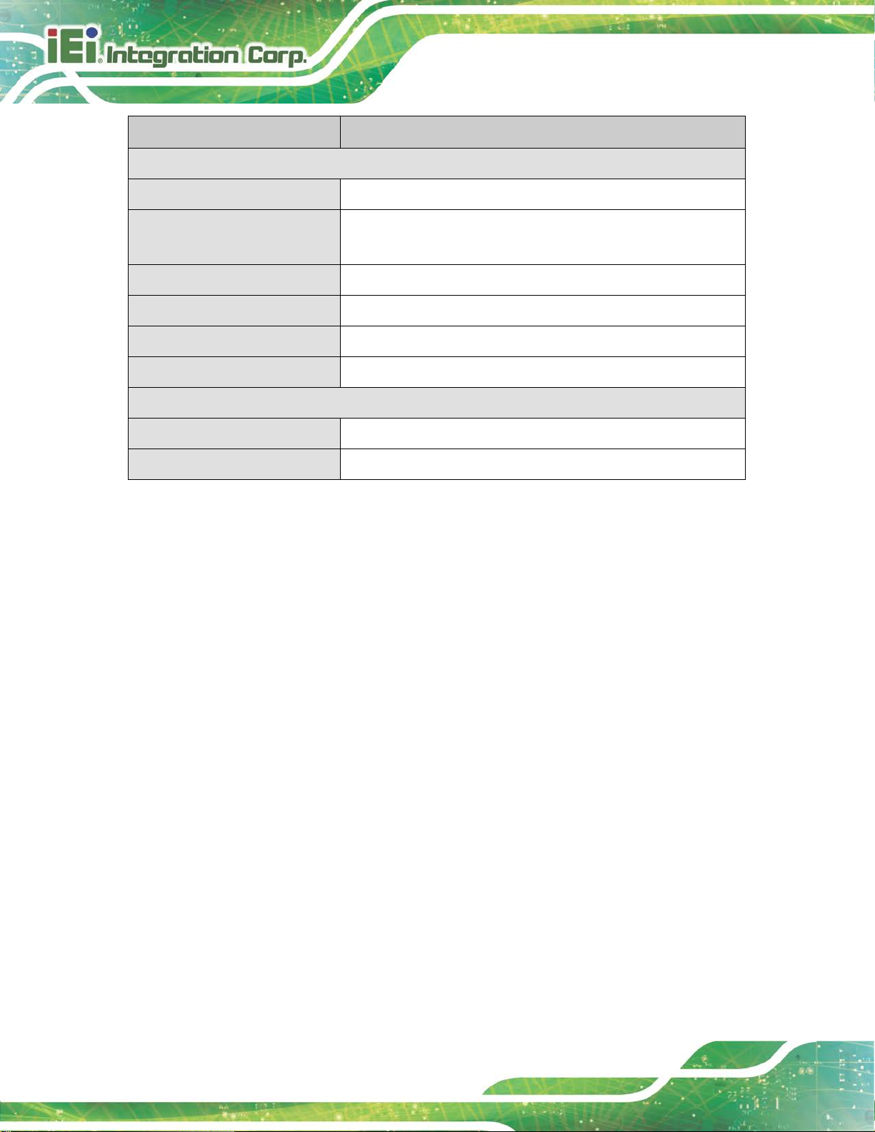
Specification HYPER-RK39
Environmental and Power Specifications
Power Supply 12 V DC input power (2-pin wafer)
Power Consumption
Operating Temperature -10°C ~ 50°C with air flow
Storage Temperature -20°C ~ 60°C
Humidity 10% ~ 95%, non-condensing
Safety CE, FCC
Physical Specifications
Dimensions 100 mm x 72 mm
Weight GW/NW 600 g / 250 g
Table 1-1: Technical Specifications
+12 V @ 3.0 A (Rockchip RK3399 SoC with 2 GB 1866 MHz
LPDDR3 memory)
Page 19

HYPER-RK39 SBC
Page 9
Chapter
2
2 Unpacking
Page 20
HYPER-RK39 SBC
Page 10
2.1 Anti-static Precautions
WARNING!
Static electricity can destroy certain elect ronics. Make sur e to follow the
ESD precautions to prevent damage to the product, and injury to the
user.
Make sure to adhere to the following guidelines:
Wear an anti-static wristband: Wearing an anti-static wristband can prevent
electrostatic discharge.
Self-grounding: Touch a grounded conductor every few minutes to discharge
any excess static buildup.
Use an anti-static pad: When configuring any circuit board, place it on an
anti-static mat.
Only handle the edges of the PCB: Don't touch the surface of the
motherboard. Hold the motherboard by the edges when handling.
2.2 Unpacking Precautions
When the HYPER-RK39 is unpacked, please do the following:
Follow the antistatic guidelines above.
Make sure the packing box is facing upwards when opening.
Make sure all the packing list items are present .
Page 21
HYPER-RK39 SBC
Page 11
2.3 Packing List
NOTE:
If any of the components listed in the checklist below are missing, do not
proceed with the installation. Contact the IEI reseller or vendor the
HYPER-RK39 was purchased from or contact an IEI sales represe ntative
directly by sending an email to sales@ieiworld.com
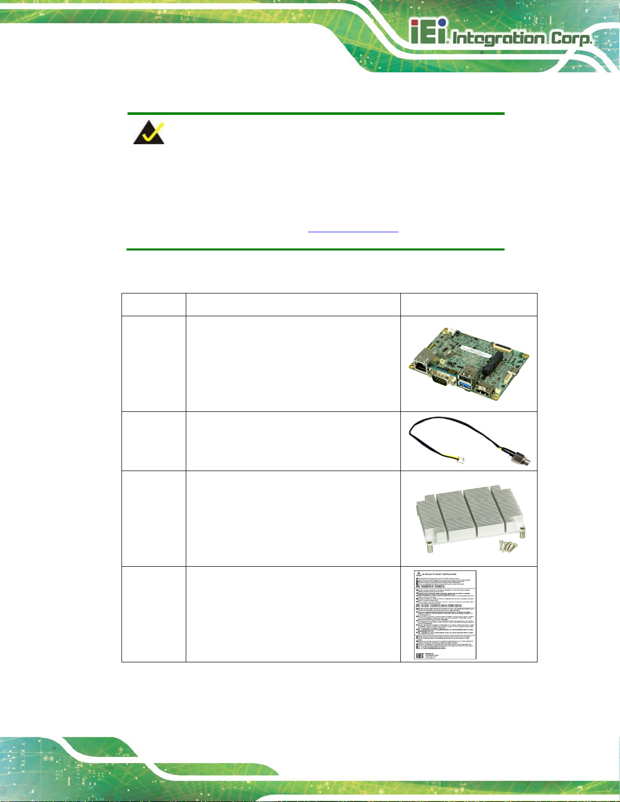
The HYPER-RK39 is shipped with the following components:
Quantity Item and Part Number Image
1 HYPER-RK39 single board computer
1 Power cable
1 Heat sink with four M3*10 screws
.
1 QIG
Page 22
HYPER-RK39 SBC
Page 12
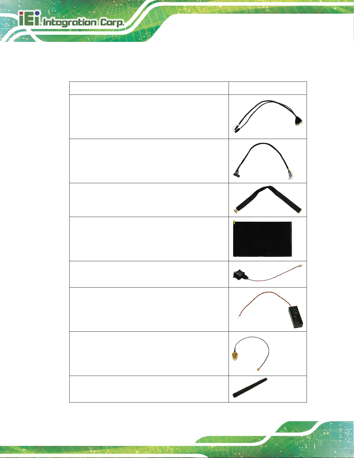
2.4 Optional Items
The following are optional components which may be separately purchased:
Item and Part Number Image
GPIO cable, 250mm, p=2.54 mm
(P/N: 32133-030000-100-RS)
Audio cable, 200mm, Jack:Ø3.5
(P/N: 32107-005200-100-RS)
eDP cable, 300 mm, p=0.5 mm
(P/N: 32602-030700-100-RS)
11.6" ePD LCD-TFT panel (1920x1080, 280cd/m2)
(P/N: 23000-01160PS01-RS)
Power switch cable , 200 mm, p=1.25 mm
(P/N: 19S00-015600-100-RS)
1.5 W speaker with cable (300 mm)
(P/N: 19800-025000-100-RS)
IPEX to SMA RF cable, 213 mm
(P/N: 32501-000705-100-RS)
Wi-Fi antenna, 108 mm
(P/N: 32505-004800-100-RS)
Page 23

HYPER-RK39 SBC
Page 13
Camera module, 2592x1944 sensor type
(P/N: 7I001-COC794A5SFE-RS)
60 W power adapter
(P/N: 63040-010060-120-RS)
L TE Antenna
(P/N: 32505-004200-100-RS)
LTE module* (PCIe Mini, WCDMA/HSPA+/LTE,
SIM7500A)
(P/N: 27552-000001-RS)
LTE module* (PCIe Mini, WCDMA/HSPA+/LTE,
SIM7500SA)
(P/N: 27552-000003-RS)
*A SIM card slot board shown below has to be installed with the LTE module:
Page 24

HYPER-RK39 SBC
Page 14
Chapter
3
3 Connectors
Page 25
HYPER-RK39 SBC
Page 15
3.1 Peripheral Interface Connectors
This chapter details all the internal and external connectors.
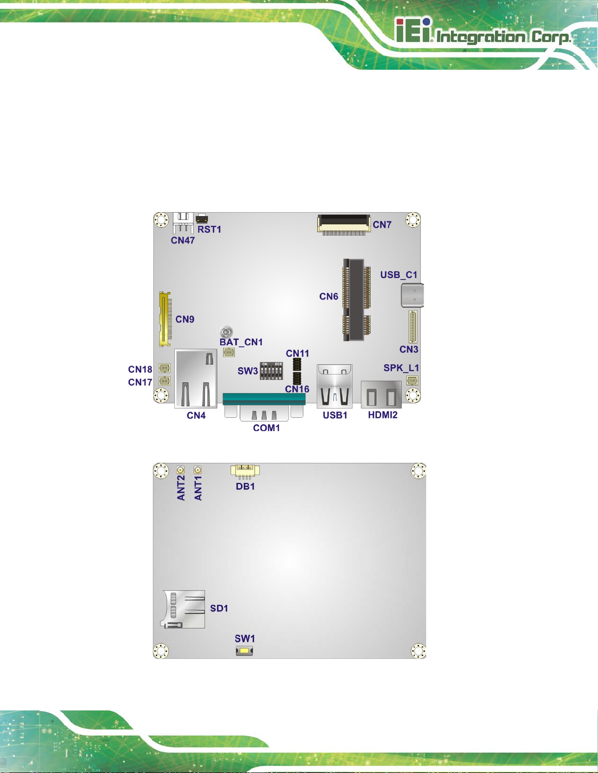
3.1.1 HYPER-RK39 Layout
The figures below show all the connectors and jump ers.
Figure 3-1: Connector and Jumper Locations (Front Side)
Figure 3-2: Connector and Jumper Locations (Solder Side)
Page 26

HYPER-RK39 SBC
Page 16
3.1.2 Peripheral Interface Connectors
The table below lists all the connectors on the board.
Connector Type Label
Antenna connector RF coaxial ANT1, ANT2
Battery connector 2-pin wafer BAT_CN1
Camera connector 30-pin FPC CN7
Debug port 4-pin wafer DB1
Earphone connector 10-pin wafer CN3
eDP connector 30-pin wire-to-board CN9
General purpose I/O connectors 10-pin header CN11, CN16
microSD slot microSD slot SD1
PCIe Mini slot Full-size PCIe Mini slot CN6
Power connector 2-pin wafer, 180° CN47
Power button connector 2-pin wafer CN17
Power key connector 2-pin wafer CN18
Reset button Push button RST1
Speaker connector 2-pin wafer SPK_L1
Programming switch
(for internal engineering use only)
Table 3-1: Peripheral Interface Connectors
Push button/DIP switch SW1, SW3
Page 27
HYPER-RK39 SBC
Page 17
3.1.3 External Interface Panel Connectors
The table below lists the connectors on the external I /O panel.
Connector Type Label
HDMI connector HDMI HDMI2
LAN connector RJ-45 CN4
RS-232/422/485 connector DB-9 COM1
USB 2.0 & USB 3.1 combo connector USB 2.0 & USB 3.1 USB1
USB 3.1 Type-C connector USB 3.1 Type-C USB_C1
Table 3-2: Rear Panel Connectors
3.2 Internal Peripheral Connectors
The section describes all of the connectors on the HYPER-RK39.
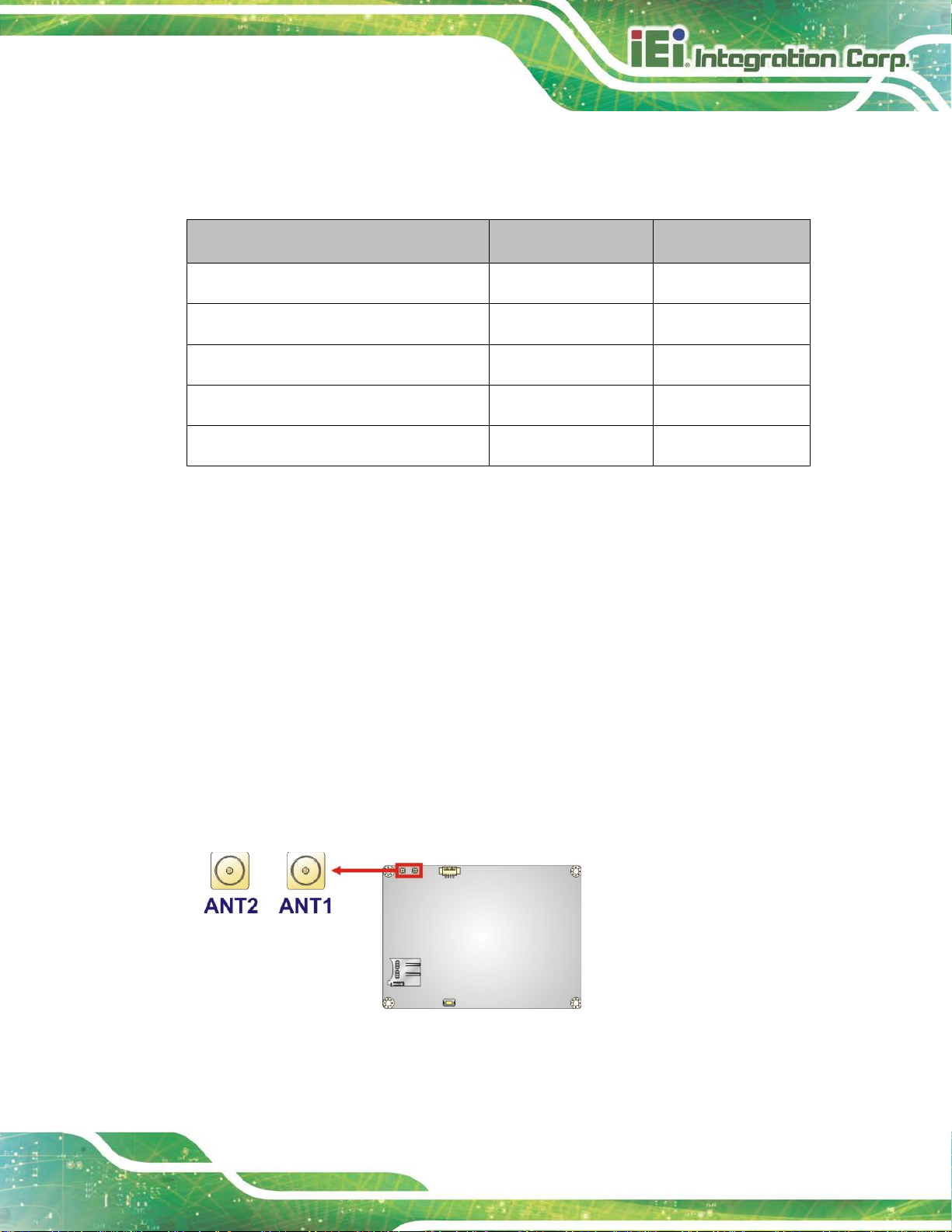
3.2.1 Antenna Connectors
CN Label:
CN Type:
CN Location:
The antenna connectors are connected to Wi-Fi RF cables.
ANT1, ANT2
RF coaxial connector
See Figure 3-3
Figure 3-3: Antenna Connector Location
Page 28

HYPER-RK39 SBC
Page 18
Risk of explosion if battery is replaced by an incorrect type. Only
Dispose of used batteries according to instructions and local
3.2.2 Battery Connector
CAUTION:
certified engineers should replace the on-board battery.
regulations.
NOTE:
It is recommended to attach the RTC battery onto the system chassis
in which the HYPER-RK39 is installed.
CN Label:
CN Type:
CN Location:
CN Pinouts:
The battery connector is connected to the system battery. The battery provides power to
the system clock to retain the time when power is turned off.
BAT_CN1
2-pin wafer, p=1.25 mm
See Figure 3-4
See Table 3-3
Figure 3-4: Battery Connector Location
Page 29

HYPER-RK39 SBC
Page 19
Pin Description
1 VBAT+
2 GND
Table 3-3: Battery Connector Pinouts
3.2.1 Camera Connector
CN Label: CN7
CN Type:
CN Location:
CN Pinouts:
The camera connector is connected to a camera module.
30-pin FPC, p=0.5 mm
See Figure 3-5
See Table 3-4
Figure 3-5: Camera Connector Location
PIN NO. DESCRIPTION PIN NO. DESCRIPTION
1 CAM LED- 16 NC
2 CAM LED+ 17 NC
3 2.8V 18 RESET
4 GND 19 NC
5 GND 20 NC
6 GND 21 NC
7 MIPI_D1_P 22 I2C SDA
8 MIPI_D1_N 23 I2C SCL
9 GND 24 Power down
10 MIPI_CLK_P 25 MCLK
Page 30

HYPER-RK39 SBC
Page 20
PIN NO. DESCRIPTION PIN NO. DESCRIPTION
11 MIPI_CLK_N 26 1.5V
12 GND 27 1.8V
13 MIPI_D0_P 28 GND
14 MIPI_D0_N 29 2.8V
15 GND 30 GND
Table 3-4: Camera Connector Pinouts
3.2.1 Debug Port
CN Label: DB1
CN Type:
CN Location:
CN Pinouts:
The debug port is for board debugging.
4-pin wafer, p=1.25 mm
See Figure 3-6
See Table 3-5
Figure 3-6: Debug Port Location
Pin Description
1 GND
2 RX
3 TX
4 GND
Table 3-5: Debug Port Pinouts
Page 31

HYPER-RK39 SBC
Page 21
3.2.1 Earphone Connector
CN Label: CN3
CN Type:
CN Location:
CN Pinouts:
10-pin wafer , p=1.00 mm
See Figure 3-7
See Table 3-6
The earphone connector connects to an earphone jack module.
Figure 3-7: Earphone Connector Location
Pin Description
1 NC
2 CPVREF
3 DET
4 MIC
5 Pull-down
6 HP R
7 GND
8 GND
9 HP L
10 NC
Table 3-6: Earphone Connector Pinouts
Page 32
HYPER-RK39 SBC
Page 22
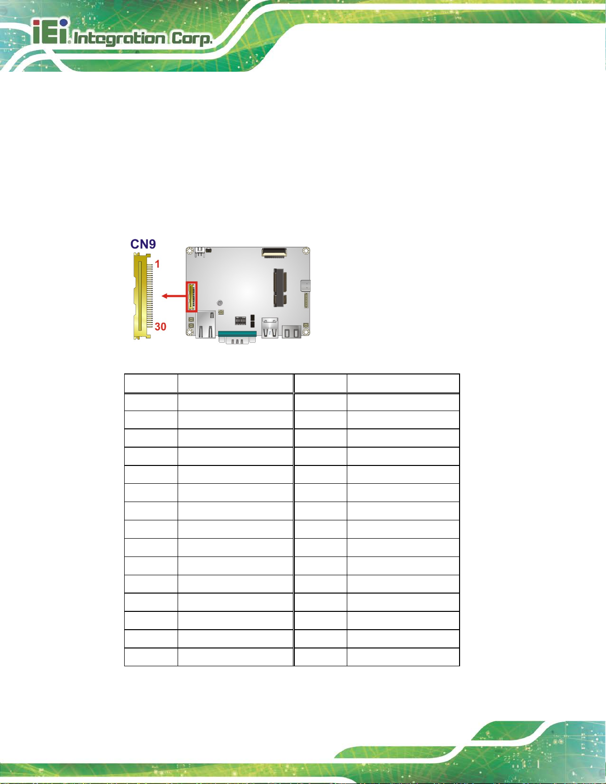
3.2.1 eDP Connector
CN Label: CN9
CN Type:
CN Location:
CN Pinouts:
30-pin wire-to-board, p=0.5 mm
See Figure 3-8
See Table 3-7
The eDP connector connects to an LCD panel.
Figure 3-8: eDP Connector Location
Pin Description Pin Description
1 NC 16 GND
2 GND 17 HPD
3 TX1N 18 GND
4 TX1P 19 GND
5 GND 20 GND
6 TX0N 21 GND
7 TX0P 22 LCD EN
8 GND 23 PWM
9 AUXP 24 I2C SDA
10 AUXN 25 I2C SCL
11 GND 26 12V
12 3V3 27 12V
13 3V3 28 12V
14 GND 29 12V
15 GND 30 GND
Table 3-7: eDP Connector Pinouts
Page 33
HYPER-RK39 SBC
Page 23
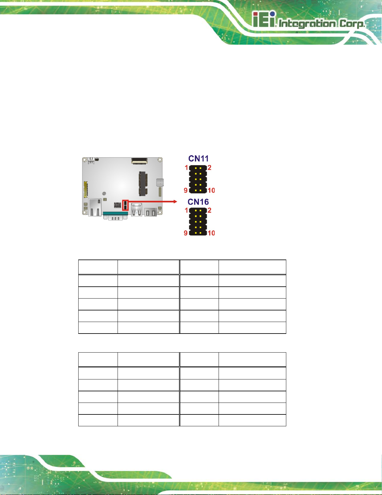
3.2.2 General Purpose I/O Connector
CN Label: CN11, CN16
CN Type:
CN Location:
CN Pinouts:
The general purpose I/O connector can control external devices.
Figure 3-9: General Purpose Connector Locations
PIN NO. DESCRIPTION PIN NO. DESCRIPTION
10-pin header, p=1.00 mm
See Figure 3-9
See Table 3-8 and Table 3-9
1 GPIO 2 NC
3 GPIO 4 NC
5 GPIO 6 NC
7 +5V 8 NC
9 GND 10 NC
Table 3-8: General Purpose Connector (CN11) Pinouts
PIN NO. DESCRIPTION PIN NO. DESCRIPTION
1 +3.3V 2 GPIO
3 GND 4 GPIO
5 I2C SDA 6 GPIO
7 I2C SCL 8 GPIO
9 NC 10 GPIO
Table 3-9: General Purpose Connector (CN16) Pinouts
Page 34
HYPER-RK39 SBC
Page 24
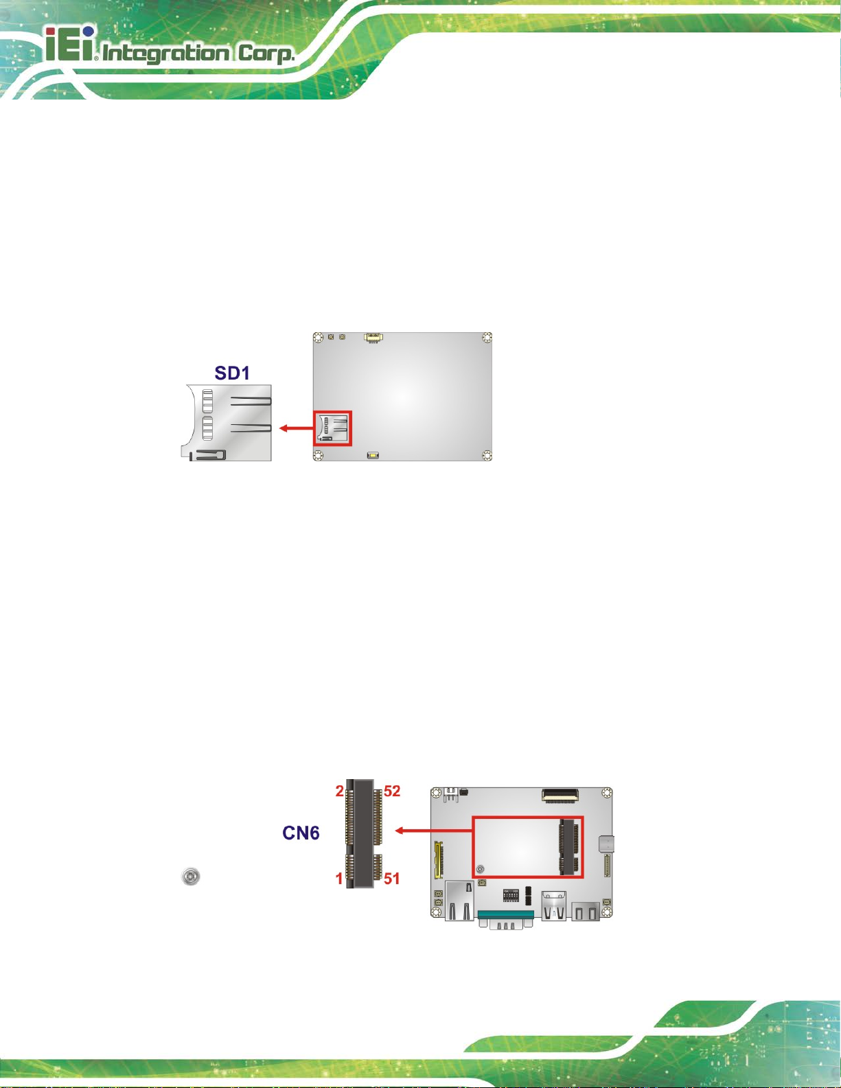
3.2.1 microSD Slot
CN Label: SD1
CN Type:
CN Location:
The microSD slot accepts microSD cards.
Figure 3-10: microSD Slot Location
microSD slot
See Figure 3-10
3.2.1 PCIe Mini Card Slot
CN Label: CN6
CN Type:
CN Location:
CN Pinouts:
The PCIe Mini card slot is for installing PCIe M i ni expansion cards.
Figure 3-11: PCIe Mini Card Slot Location
Full-size PCIe Mini card slot
See Figure 3-11
See Table 3-10
Page 35
HYPER-RK39 SBC
Page 25
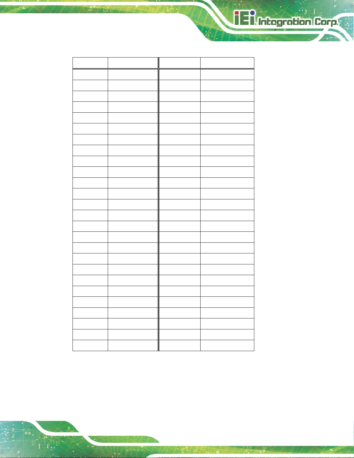
Pin Description Pin Description
1 NC 2 3.8V
3 NC 4 GND
5 NC 6 NC
7 NC 8 NC
9 GND 10 NC
11 NC 12 NC
13 NC 14 NC
15 GND 16 NC
17 NC 18 GND
19 NC 20 NC
21 GND 22 RESET
23 NC 24 NC
25 NC 26 GND
27 GND 28 NC
29 GND 30 NC
31 NC 32 NC
33 NC 34 GND
35 GND 36 USB D37 GND 38 USB D+
39 3.8V 40 GND
41 3.8V 42 NC
43 GND 44 NC
45 NC 46 NC
47 NC 48 NC
49 NC 50 GND
51 NC 52 3.8V
Table 3-10: PCIe Mini Card Slot Pinouts
Page 36
HYPER-RK39 SBC
Page 26
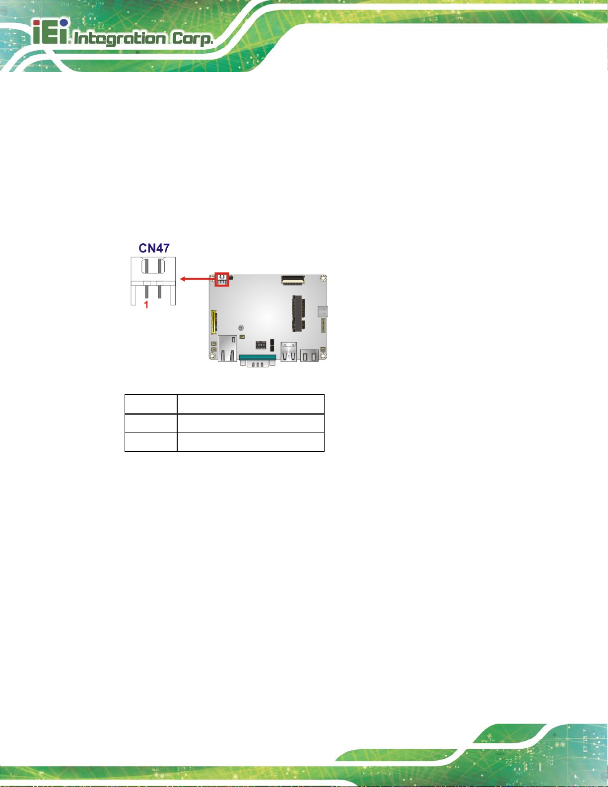
3.2.2 Power Connector
CN Label:
CN Type:
CN Location:
CN Pinouts:
The power connector provides +12 V power to the board.
Figure 3-12: Power Connector Location
Pin Description
CN47
2-pin wafer, p=2.5 mm
See Figure 3-12
See Table 3-11
1 DC +12 V
2 GND
Table 3-11: Power Connector Pinouts
Page 37
HYPER-RK39 SBC
Page 27
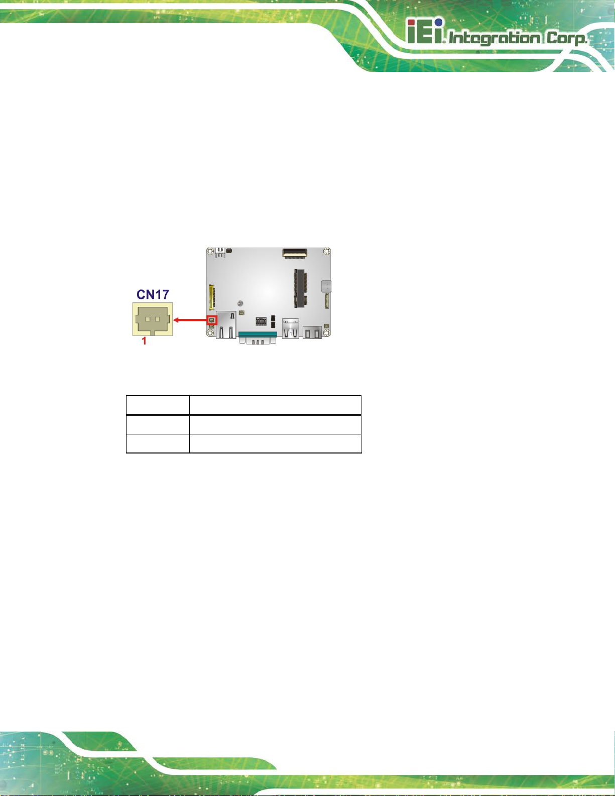
3.2.1 Power Button Connector
CN Label: CN17
CN Type:
CN Location:
CN Pinouts:
The power button connector is connected to a powe r switch on the system chassis.
Figure 3-13: Power Button Connector Location
2-pin wafer, p=1.25 mm
See Figure 3-13
See Table 3-12
Pin Description
1 GND
2 Power ON
Table 3-12: Power Button Connector Pinouts
Page 38
HYPER-RK39 SBC
Page 28
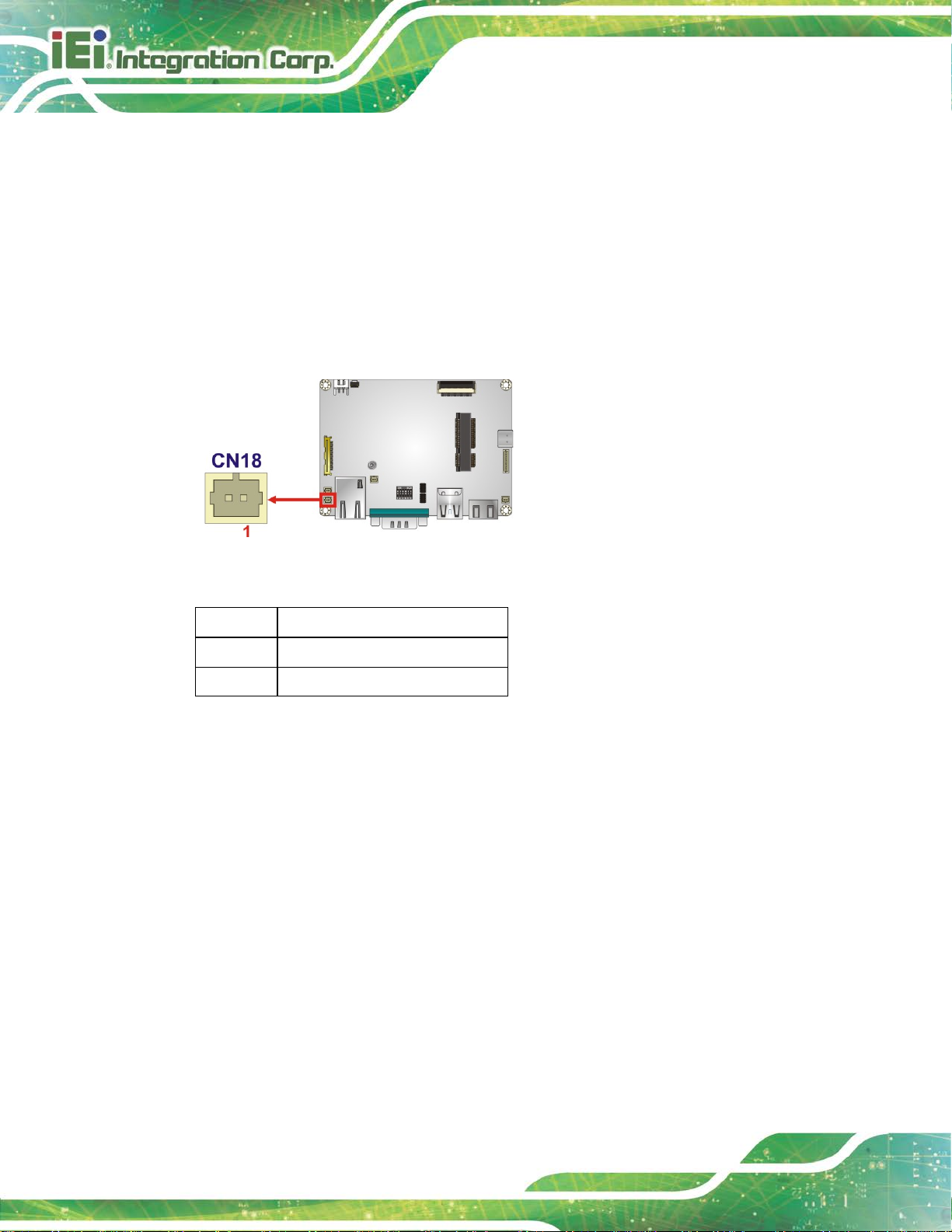
3.2.2 Power Key Connector
CN Label: CN18
CN Type:
CN Location:
CN Pinouts:
The power key connector is connected to a power key.
Figure 3-14: Power Key Connector Location
2-pin wafer , p=1.25 mm
See Figure 3-14
See Table 3-13
Pin Description
1 GND
2 EN
Table 3-13: Power Key Connector Pinouts
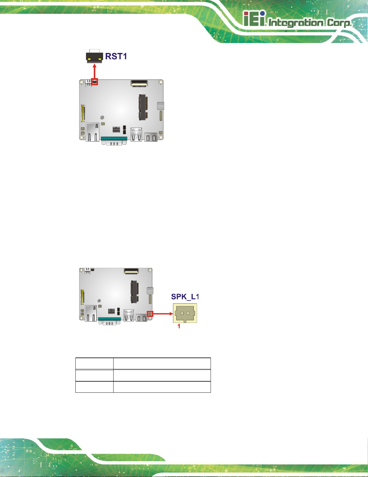
3.2.1 Reset Button
CN Label: RST1
CN Type:
CN Location:
Push the reset button to restart the system.
Push button
See Figure 3-15
Page 39
HYPER-RK39 SBC
Page 29
Figure 3-15: Reset Button Location
3.2.1 Speaker Connector
CN Label: SPK_L1
CN Type:
CN Location:
CN Pinouts:
This connector is connected to a speaker.
Figure 3-16: Speaker Connector Pinouts
2-pin wafer , p=1.25 mm
See Figure 3-16
See Table 3-14
Pin Description
1 Speaker+
2 Speaker-
Table 3-14: Speaker Connector Pinouts
Page 40
HYPER-RK39 SBC
Page 30
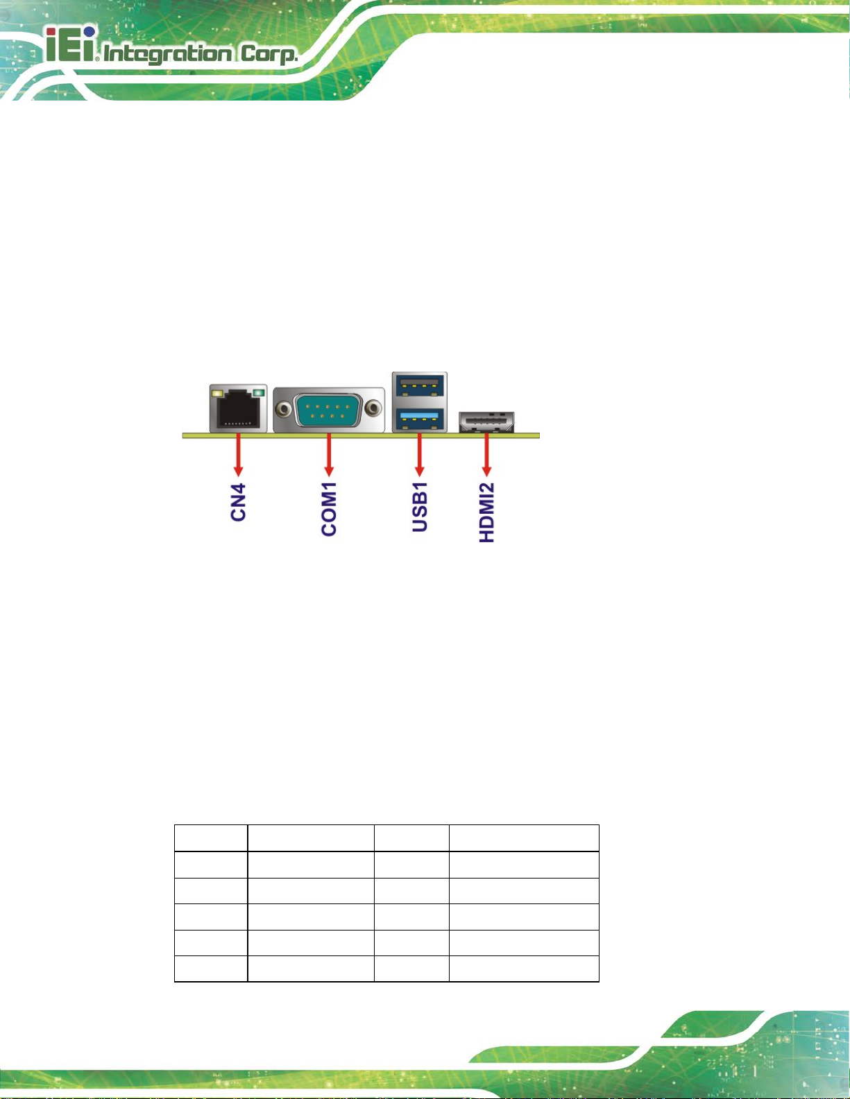
3.3 External Peripheral Interface Connector Panel
Figure 3-17 shows the HYPER-RK39 external peripheral interface connector (EPIC)
panel. The EPIC panel consists of the following:
1 x HDMI connector
1 x GbE LAN connector
1 x RS-232/422/485 connector
1 x USB 2.0 connector
1 x USB 3.1 connector
Figure 3-17: External Peripheral Interface Co nn ector
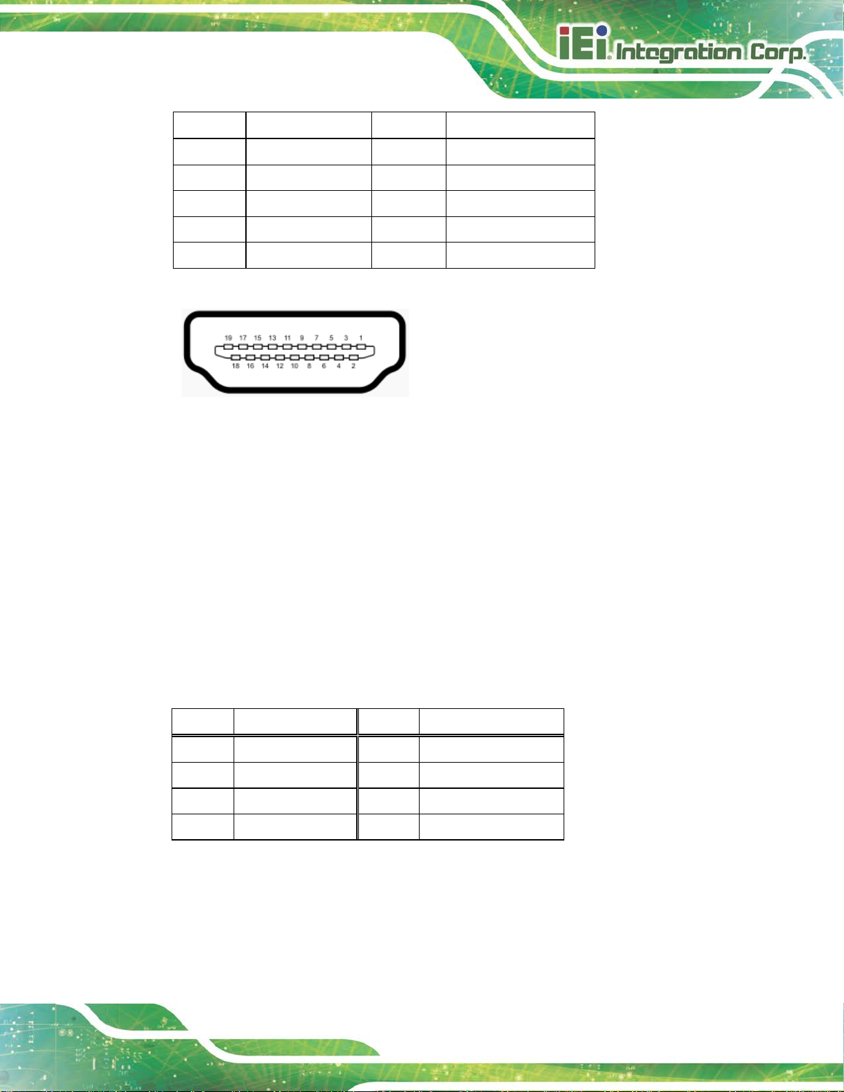
3.3.1 HDMI Connector
CN Label: HDMI2
CN Type:
CN Location:
CN Pinouts:
The HDMI connector can connect to an HDMI device.
Pin Description Pin Description
1 HDMI_DATA2 2 GND
3 HDMI_DATA2# 4 HDMI_DATA1
5 GND 6 HDMI_DATA1#
7 HDMI_DATA0 8 GND
HDMI
See Figure 3-17
See Table 3-15
9 HDMI_DATA0# 10 HDMI_CLK
Page 41
HYPER-RK39 SBC
Page 31
Pin Description Pin Description
11 GND 12 HDMI_CLK#
13 N/C 14 N/C
15 HDMI_SCL 16 HDMI_SDA
17 GND 18 +5V
19 HDMI_HPD
Table 3-15: HDMI Connector Pinouts
Figure 3-18: HDMI Connector
3.3.2 LAN Connector
CN Label: CN4
CN Type:
CN Location:
CN Pinouts:
The LAN connector connects to a local network.
RJ-45
See Figure 3-17
See Figure 3-19 and Table 3-16
Pin Description Pin Description
1 LAN_MDI0+ 7 LAN_MDI2+
2 LAN_MDI0- 8 LAN_MDI23 LAN_MDI1+ 9 LAN_MDI3+
4 LAN_MDI1- 10 LAN_MDI3-
Table 3-16: LAN Pinouts
Page 42

HYPER-RK39 SBC
Page 32
Figure 3-19: LAN Connector
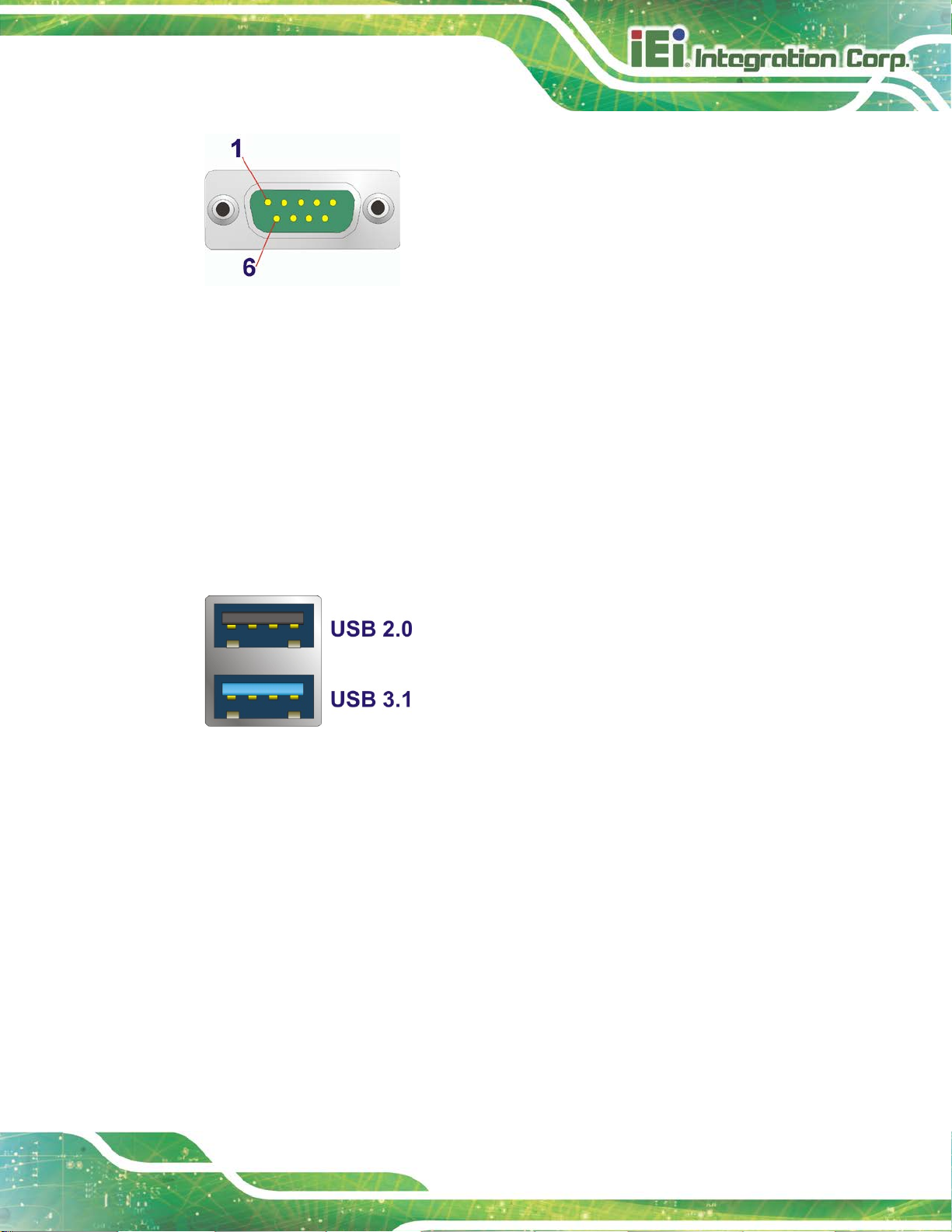
3.3.1 RS-232/422/485 Serial Port Connector (COM1)
CN Label: COM1
CN Type:
CN Location:
CN Pinouts:
DB-9 connector
See Figure 3-17
See Table 3-17 and Figure 3-20
The pinouts for RS-232, RS-422 and RS-485 communication are shown below.
Pin RS-232 RS-422 RS-485
1 -- TX- D2 RX TX+ D+
3 TX RX+ -4 -- RX- -5 GND -- -6 -- -- -7 -- -- -8 -- -- -9 -- -- --
Table 3-17: COM1 Pinouts
Page 43
HYPER-RK39 SBC
Page 33
Figure 3-20: Serial Port Pinouts
3.3.2 USB Connectors
CN Label: USB1
CN Type:
CN Location:
The HYPER-RK39 has one external USB 3.1 Gen 1 port and one USB 2.0 port. The USB
connector can be connected to a USB 2.0 or USB 3.1 device.
Figure 3-21: External USB Type-A Ports
USB 3.1 Gen1 Type-A and USB 2.0 Type-A
See Figure 3-17
CN Label: USB_C1
CN Type:
USB 3.1 Gen1 Type-C
CN Location:
The HYPER-RK39 also has one external USB 3.1 Type-C port that supports USB Type-C
devices.
See Figure 3-22
Page 44

HYPER-RK39 SBC
Page 34
Figure 3-22: External USB 3.1 Type-C Port
Page 45

HYPER-RK39 SBC
Page 35
Chapter
4
4 Installation
Page 46

HYPER-RK39 SBC
Page 36
Failure to take ESD precautions during the installation of the
4.1 Anti-static Precautions
WARNING:
HYPER-RK39 may result in permanent damage to the HYPER-RK39
and severe injury to the user.
Electrostatic discharge (ESD) can cause serious damage to electronic components,
including the HYPER-RK39. Dry climates are especially susceptible to ESD. It is therefore
critical that whenever the HYPER-RK39 or any other electrical component is handled, the
following anti-static precautions are strictly adhered to.
Wear an anti-static wristband: Wearing a simple anti-static wristband can
help to prevent ESD from damaging the board.
Self-grounding Before handling the board, touch any grounded conducting
material. During the time the board is handled, f requently touch any
conducting materials that are connected to the ground.
Use an anti-static pad: When configuring the HYPER-RK39, place it on an
anti-static pad. This reduces the possibility of ESD damaging the
HYPER-RK39.
Only handle the edges of the PCB: When handling the PCB, hold the PCB
by the edges.
4.2 Installation Considerations
NOTE:
The following installation notices and installation considerations should
be read and understood before installation. All installation notices must
be strictly adhered to. Failing to adhere to these precautions may lead
to severe damage and injury to the person performing the installation.
Page 47

HYPER-RK39 SBC
Page 37
WARNING:
The installation instructions described in this manual should be carefully
followed in order to prevent damage to the HYPER-RK39, component s and
injury to the user.
Before and during the installation please DO the following:
Read the user manual:
o The user manual provides a complete description of the HYPER-RK39
installation instructions and configuration opt i ons.
Wear an electrostatic discharge cuff (ESD):
o Electronic components are easily damaged by ESD. Wearing a n ESD cuff
removes ESD from the body and helps prevent ESD damage.
Place the HYPER-RK39 on an antistatic pad:
o When installing or configuring the motherboa rd, pl ace it on an antistatic
pad. This helps to prevent potential ESD damage.
Turn all power to t he HYPER-RK39 off:
o When working with the HYPER-RK39, make sure that it is disconnected
from all power supplies and that no elect ricity is b eing f ed into the sy stem.
Before and during the installation of the HYPER-RK39:
DO NOT remove any of the stickers on the PCB board. These st i ckers are
required for warranty validation.
DO NOT use the product before ve rifying all the cables an d powe r conne ctors
are properly connected.
DO NOT allow screws to come in contact with the PCB circuit, connector pins,
or its components.
Page 48
HYPER-RK39 SBC
Page 38
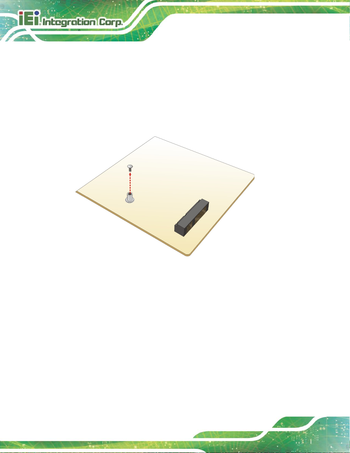
4.3 Full-size PCIe Mini Card Installation
The PCIe Mini card slot allows installation of either a full-size PCIe Mini card. To install a
full-size PCIe Mini card, please follow the steps below.
Step 1: Locate the PCIe Mini card slot. See Chapter 3.
Step 2: Remove the retention screw. Remove the retention sc rew as shown in
Figure 4-1.
Figure 4-1: Removing the Retention Screw
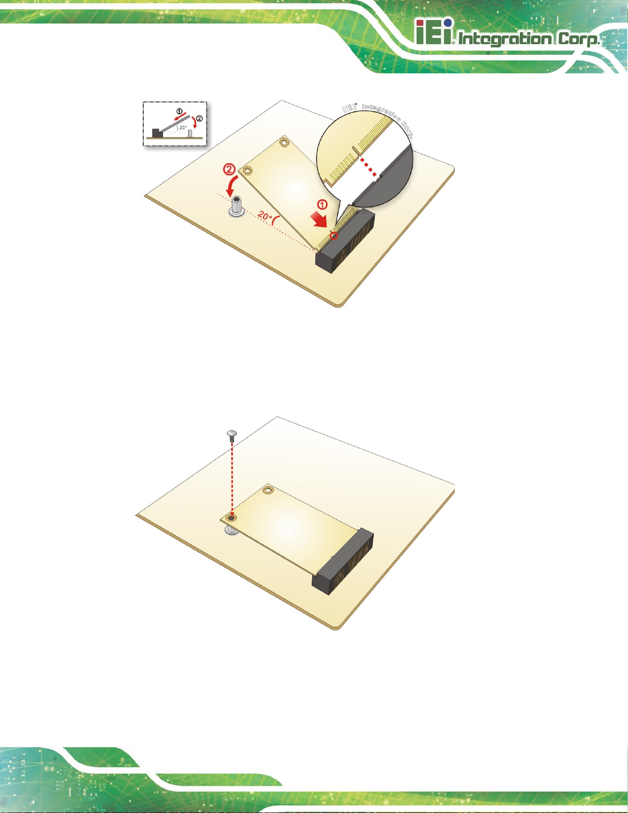
Step 3: Insert into the socket at an angle. Line up the notch on the card w ith t he notch
on the slot. Slide the PCIe Mini card into the socket at an angle of a bout 20º
(Figure 4-2).
Page 49
HYPER-RK39 SBC
Page 39
Figure 4-2: Inserting the Full-size PCIe Mini Card into the Slot at an Angle
Step 4: Secure the full-size PCIe Mini card. Secure the full-size PCIe Mini card with
the retention screw previously removed (Figure 4-3). Step 0:
Figure 4-3: Securing the Full-size PCIe Mini Card
Page 50
HYPER-RK39 SBC
Page 40
keeping components within recommended
operating temperatures. The chassis should have fans and vents as
4.4 Chassis Installation
4.4.1 Airflow
WARNING:
Airflow is critical for
necessary to keep things cool.
The HYPER-RK39 must be installed in a chassis with ventilation holes on the sides
allowing airflow to travel through the heat sink surface. In a system with an individual
power supply unit, the cooling fan of a power supply can also help generate airflow
through the board surface.
4.4.2 Heat Sink Installation
WARNING:
1. Never run the HYPER-RK39 without the heat sink secured to the
board. The heat sink ensures the system remains cool.
2 The plastic sheet attached on the thermal pad of the heat sink must
be removed before installation.
A heat sink is shipped with the HYPER-RK39. The heat sink must be installed on to the
HYPER-RK39 before operation. The following figure shows how to install the heat sink.
Page 51

HYPER-RK39 SBC
Page 41
Figure 4-4: Heat Sink Installation
4.4.3 Motherboard Installation
To install the HYPER-RK39 motherboard into the chassis please refer to the reference
material that came with the chassis.
Page 52
HYPER-RK39 SBC
Page 42
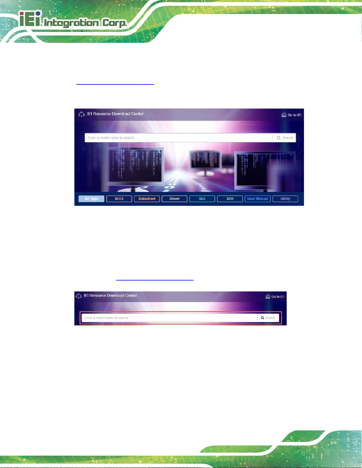
Figure 4-5: IEI Resource Download Center
4.5 Available Drivers
All the drivers for the HYPER-RK39 are available on IEI Resource Download Center
(https://download.ieiworld.com
relevant software, utilities, and documentation.
4.5.1 Driver Download
). Type HYPER-RK39 and press Enter to find all the
To download drivers from IEI Resource Download Center, follow the steps below.
Step 1: Go to https://download.ieiworld.com
Step 2: All product-related software, utilities, and documentation will be listed. You can
choose Driver to filter the result.
. Type HYPER-RK39 and press Enter.
Page 53

HYPER-RK39 SBC
Page 43
its content. On Windows 7 system, an additional tool (such as Virtual
Step 3: Click the driver file name on the page and you will be prompted with the
following window. You can download the entire ISO file (
arrow to find an individual driver and click the file name to download (
), or click the small
).
NOTE:
To install software from the downloaded ISO image file in Windows 8,
8.1 or 10, double-click the ISO file to mount it as a virtual drive to view
CD-ROM Control Panel from Microsoft) is needed to mount the file.
Page 54

HYPER-RK39 SBC
Page 44
Chapter
5
5 Android OS
Page 55
HYPER-RK39 SBC
Page 45
The HYPER-RK39 may come with Android OS pre-installed. This chapter introduces the
user interface and basic functions of Android OS in stalled in the HYPER-RK39.
5.1 Home Screen
Android OS supports multiple home screens allowing users to customize the screen with
widgets, apps and shortcuts. The following sections describe the basic technique to
manage the home screen.
5.1.1 Adding a Home Screen
To add a home screen, touch and hold an app/widget icon. The fol l owing screen appears,
indicating that a new home screen is available. Drag and relea se the icon to the new home
screen.
Figure 4-1: Adding a Home Screen
Page 56
HYPER-RK39 SBC
Page 46
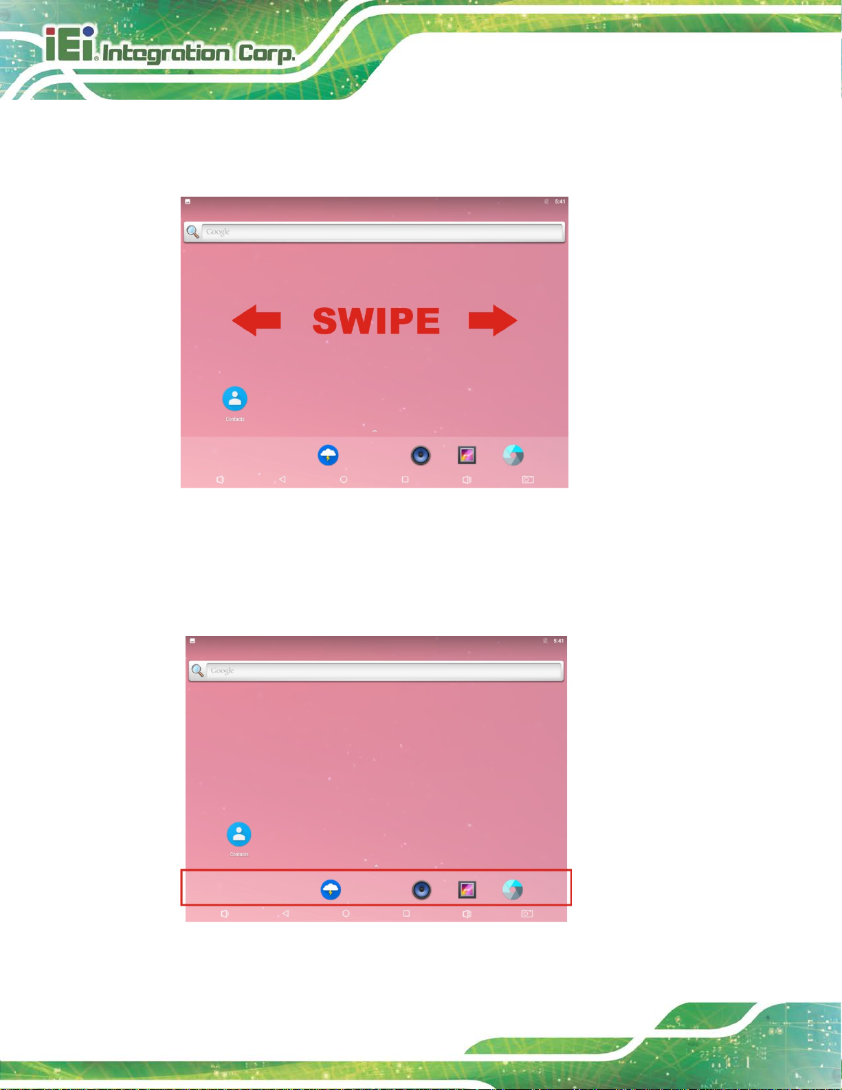
5.1.2 Switching between Home Screens
Swipe right or left to switch between home screens.
Figure 4-2: Multiple Home Screens
5.1.3 Favorites Tray
The Favorites tray at the bottom of each home screen allows users to keep the most
important or frequently used shortcuts.
Figure 4-3: Favorites Tray
Page 57

HYPER-RK39 SBC
Page 47
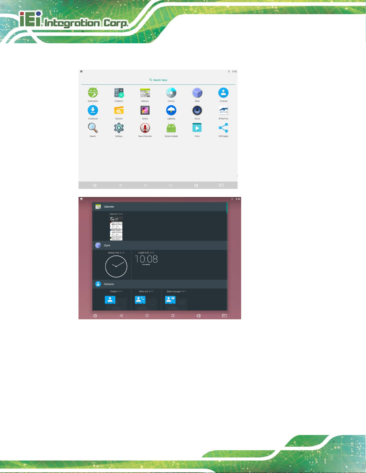
5.1.4 Adding Shortcuts
To add app or widget shortcuts on the home s cr een, follow the steps below.
Step 1: To add an app shortcut, tap the up arrow on the home screen to access the
All Apps page.
To add a widget shortcut, touch and hold the background of a home screen, then
tap WIDGETS.
Page 58
HYPER-RK39 SBC
Page 48
Step 2: Touch and hold an app icon or a widget, and drag it to the home screen.
Figure 4-4: All Apps/WIDGETS Page
Page 59
HYPER-RK39 SBC
Page 49
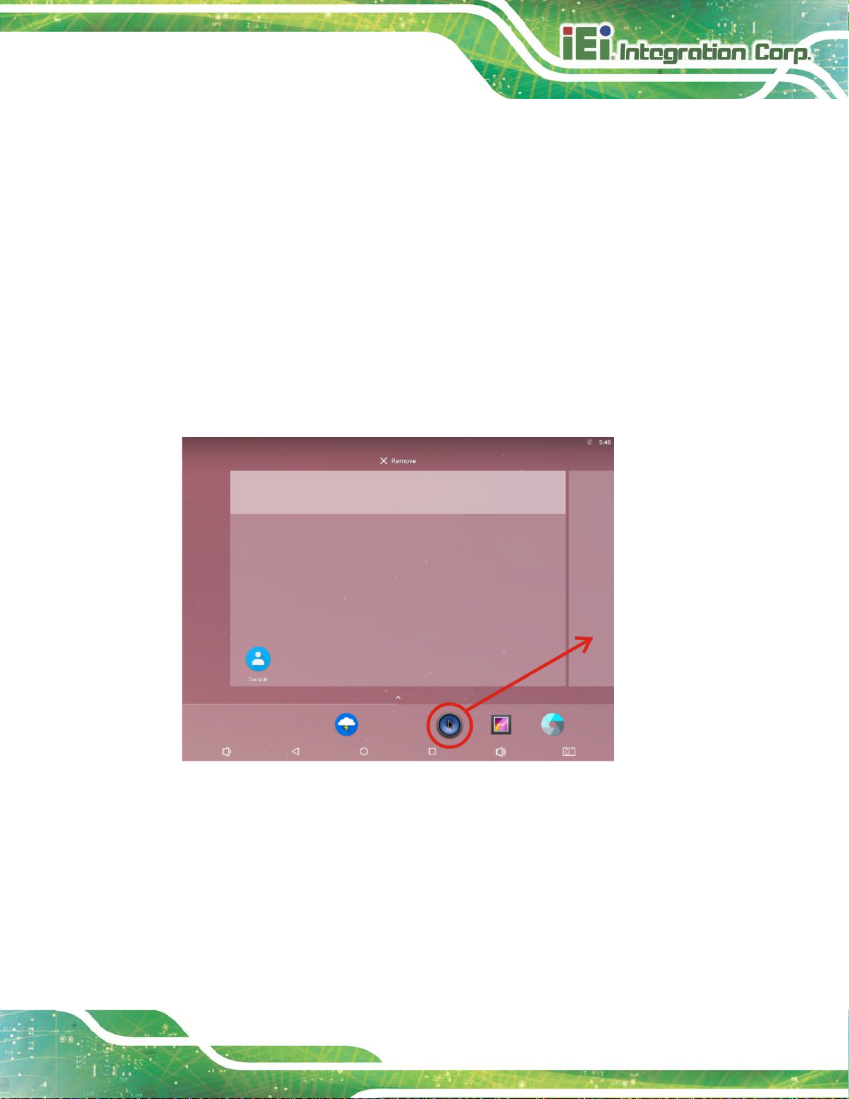
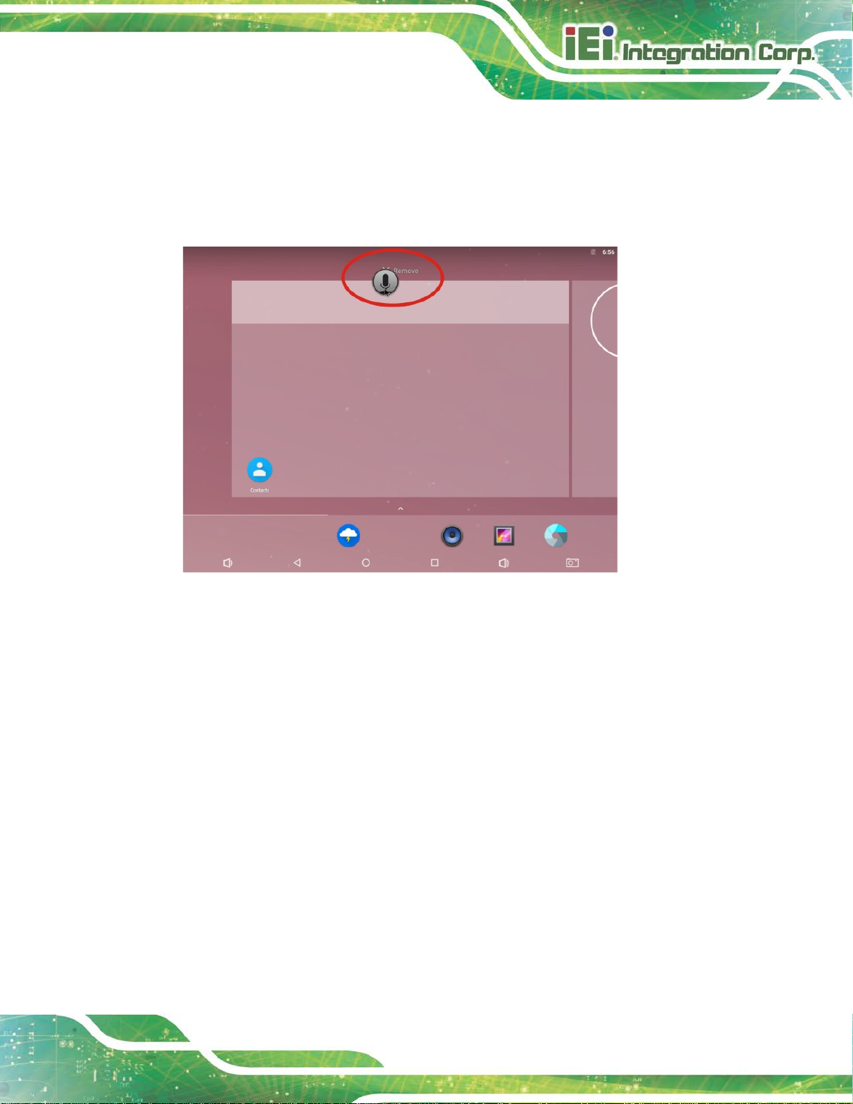
5.1.5 Arranging the Home Screen
The items on the home screen can be moved and deleted. Touch and hold an item on the
home screen and drag it where you want. To trash the item on the screen, drag it to the
Remove icon. Release the icon when it turns gray.
Figure 4-5: Trash an Item on Home Screen
Page 60

HYPER-RK39 SBC
Page 50
5.2 Navigation Buttons
The navigation buttons shown in Figure 4-8 c an always be found at the bottom of every
screen.
Figure 4-6: Navigation Buttons
Buttons Description
Table 4-1: Navigation Buttons
Tap to turn t he volume down.
Tap to return to the previous screen.
Tap to return to the home screen.
Tap to display all the recently used applications.
Tap to turn t he volume up.
Tap to take a screenshot.
Page 61

HYPER-RK39 SBC
Page 51
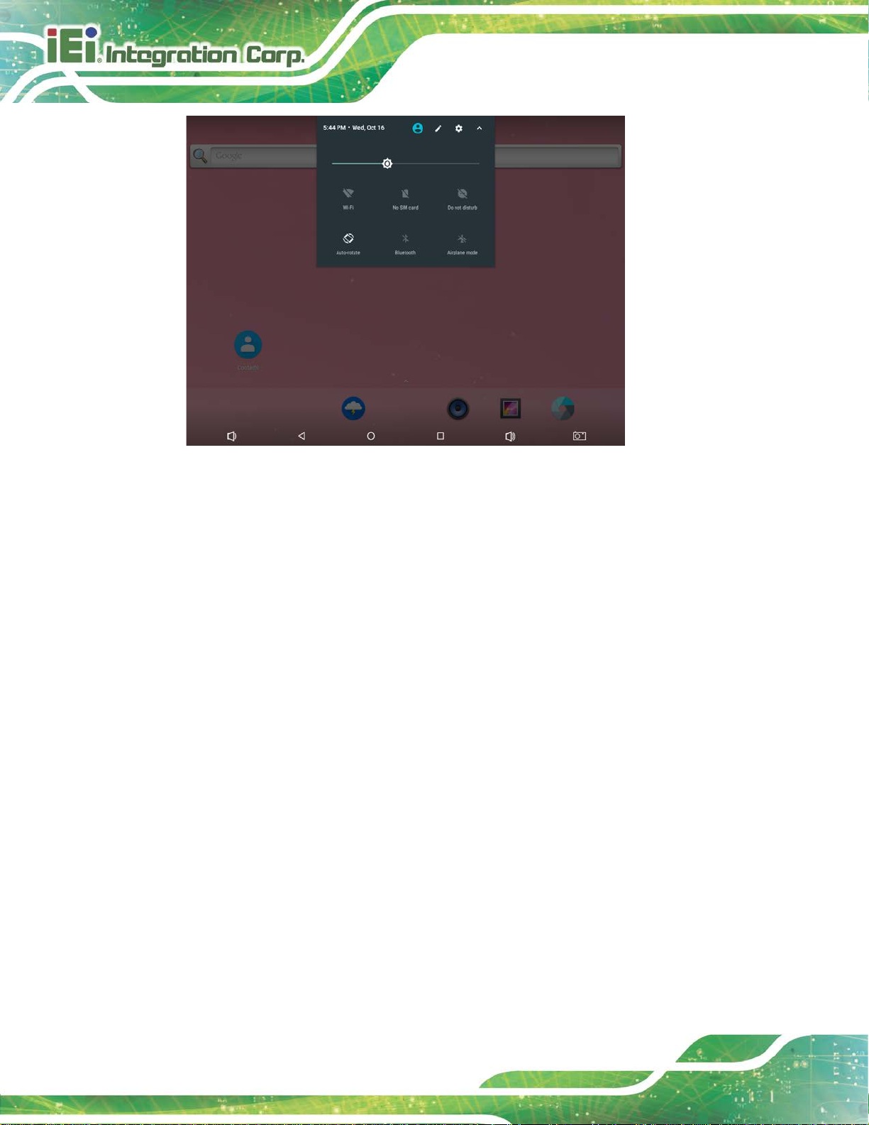
5.3 Status Bar
The status bar on the top of the screen (Figure 4-9) displays system status, such as
battery level or signal strength.
Figure 4-7: Status Bar
Swipe down from the status bar to view notification and status details (Figure 4-10).
Page 62
HYPER-RK39 SBC
Page 52
Figure 4-8: Notification List and System Status
Page 63

HYPER-RK39 SBC
Page 53
Chapter
6
6 Ubuntu OS
Page 64
HYPER-RK39 SBC
Page 54
The HYPER-RK39 may come with Ubuntu 16.04 OS pre-installed. This chapter introduces
the user interface and basic functions of Ubuntu OS installed in the HYPER-RK39.
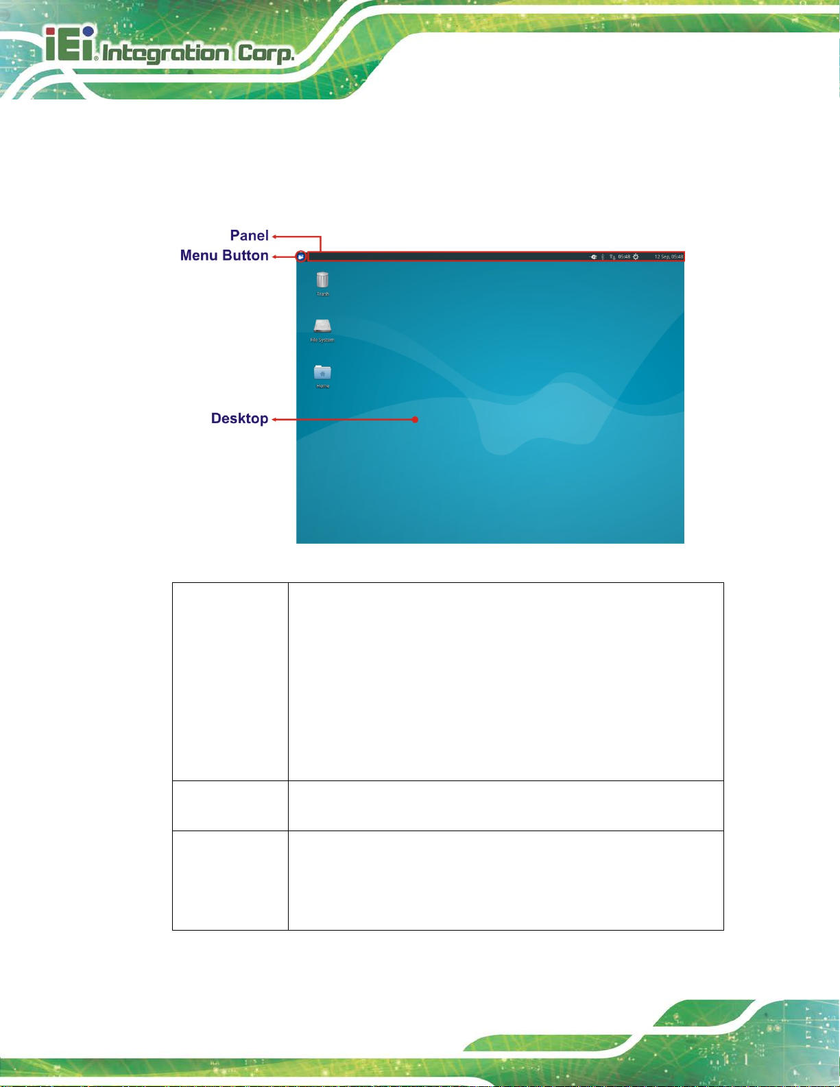
6.1 Desktop
Figure 4-1: Ubuntu Desktop
Panel It is used for starting and switching applications and for receiving information
about the system. It includes:
- Clock: displays the date and time.
- Notification Area: contains indicators which provide system information,
including network connectivity, power management and system settings.
The position of the panel, the items it contains and the Menu ar e all
customizable by right-clicking on the Panel and select Panel → Panel
Preferences.
Menu Button Clicking on the menu b utton will open the Menu, offering many choices of
applications. (See the following section for details.)
Desktop The default desktop has just three icons on it: Home (where all personal data
are stored), File System (which is the root of the filesystem) and Trash. The
desktop can be customized by right-clicking in a blank area and choosing
Desktop Settings.
Page 65

HYPER-RK39 SBC
Page 55
6.2 Menu
Figure 4-2: Ubuntu Menu
The Menu is an application launcher. After clicking on the Menu Button , a list of favorite
applications is displayed. The user can browse through all of installed applications by
clicking on the category buttons on the side. Additionally, the Menu keeps a list of the last
ten applications that the user has launched from it .
Along the bottom of the Menu window are icons for Settings Manager, Lock Screen and
Log Out.
Page 66
HYPER-RK39 SBC
Page 56
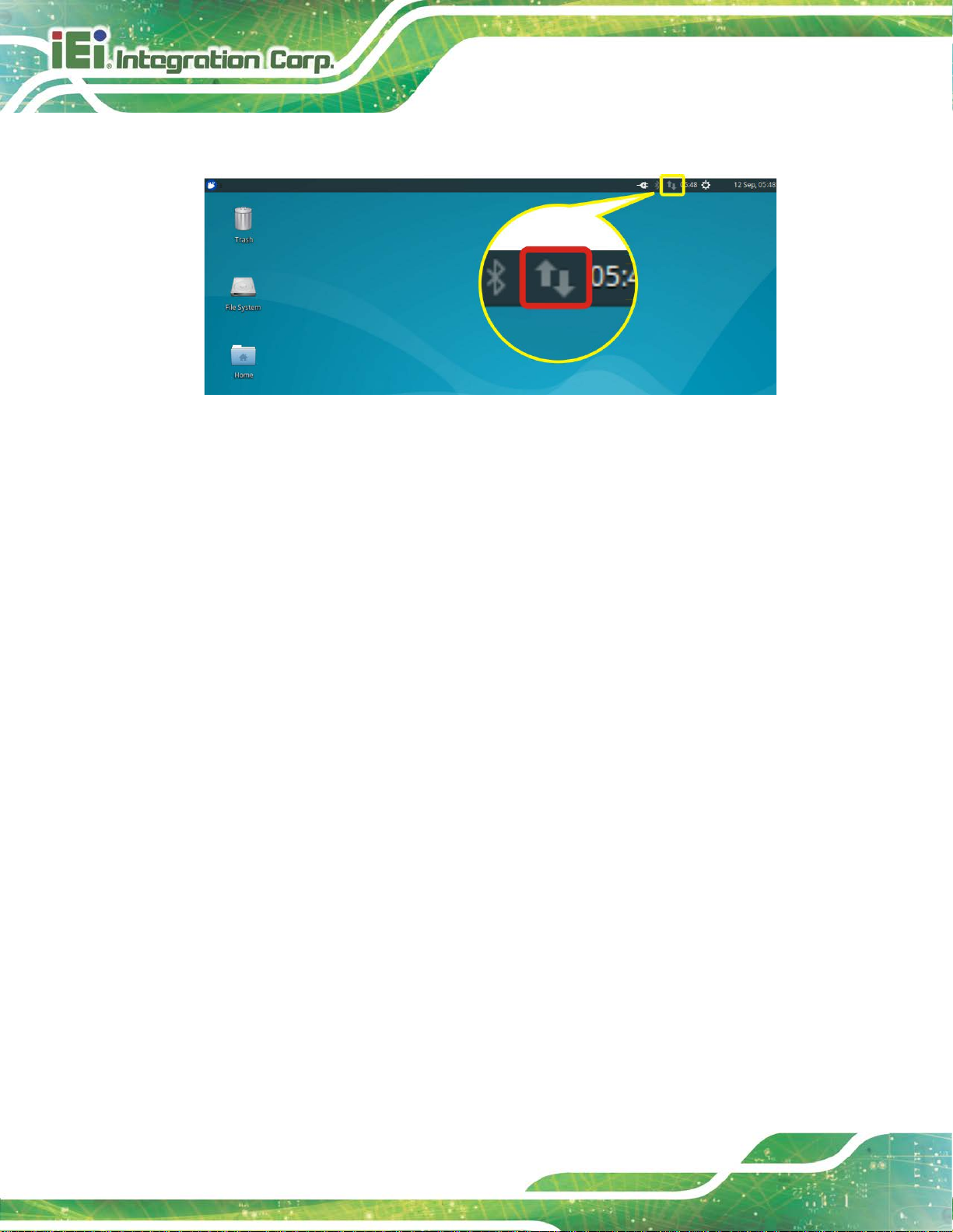
6.3 Network Connection
Figure 4-3: Ubuntu NetworkManager
Ubuntu uses NetworkManager to manage wired and wireless connections.
NetworkManager will automatically use a wired network, if one is available.
To see all available connections, click the NetworkManager icon. To connect to a network,
click the network name. To disconnect from a network, click the NetworkManager icon,
and select Disconnect. To disable (and re-enable) wired and/or wireless connections all
together, click the NetworkManager icon, then select Enable Networking and Enable
Wi-Fi.
To configure the connections, click the NetworkManager icon and select Edit. In the
dialog, select the appropriate network and press Edit or press Add to set up new
networks.
Page 67
HYPER-RK39 SBC
Page 57
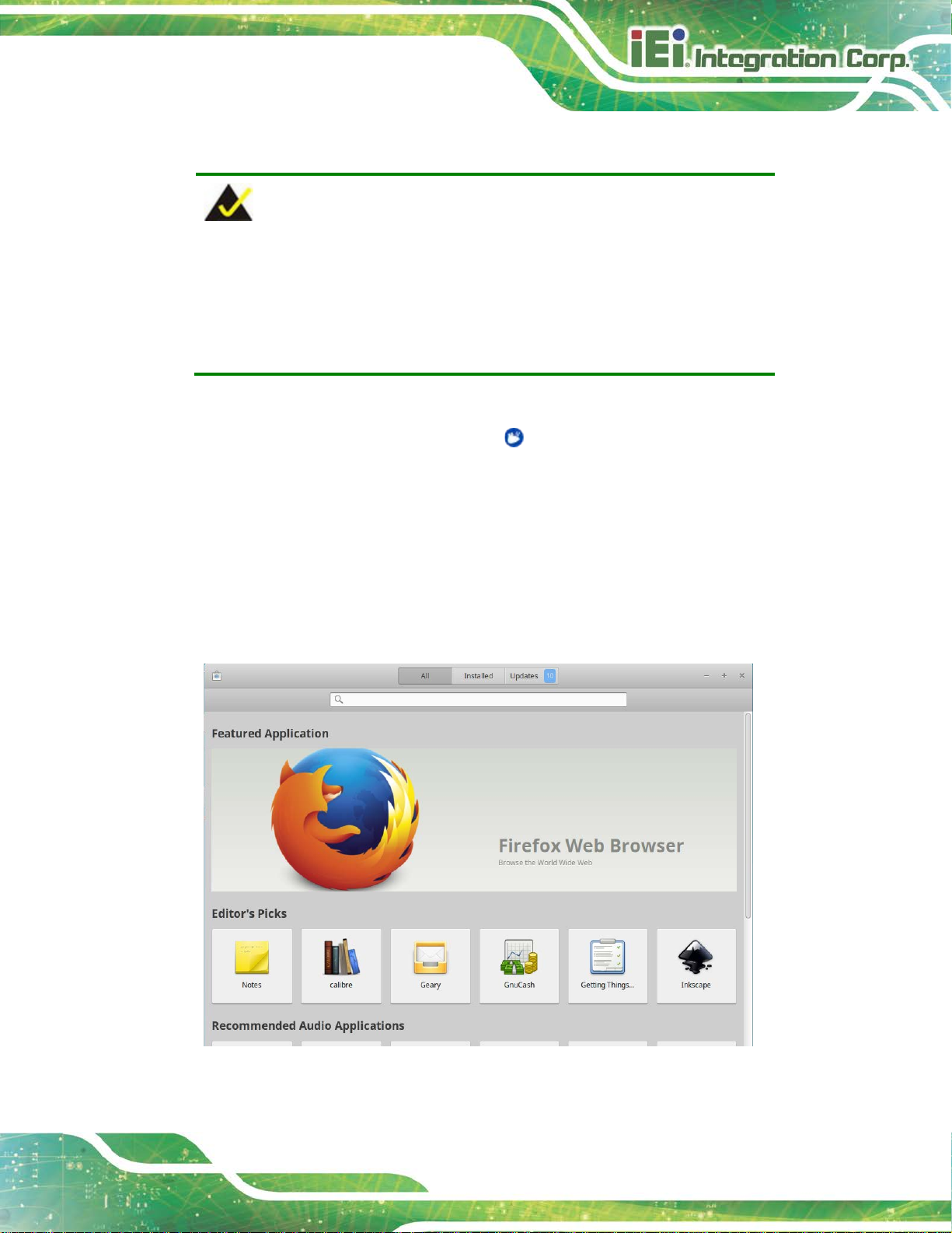
6.4 Managing Applications
NOTE:
1. To be able to install new software from the repositories, the system
must be connected to the Internet.
2. Administrative access is required to add and remov e sof tware.
The Ubuntu software repositories contain software for users to download. To access the
repositories, launch Software from the Menu .
Installing new software
Search for an application or select a category to f i nd an appl ication to install
From the application page, click Install
The user will be asked to enter the system password; once entered, installation
will begin
A shortcut to the application will be added to the Applications menu
Figure 4-4: Ubuntu Software
Page 68
HYPER-RK39 SBC
Page 58
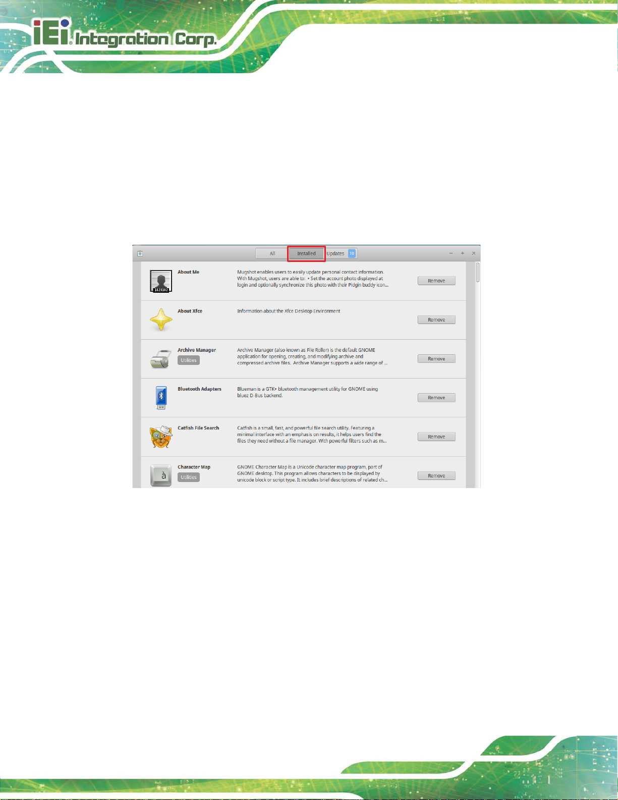
Removing software
Click Installed on the top panel
Find the application that you want to remove by using the search box or looking
through the installed applications
Select the application and click Remove
The user may be asked to enter the system password; once entered, the
application will be removed
Figure 4-5: Removing Software
Page 69

HYPER-RK39 SBC
Page 59
Appendix
A
A Regulatory Compliance
Page 70
HYPER-RK39 SBC
Page 60
This equipment complies with Part 15 of the FCC Rules. Operation is subject to the
commercial environment. This equipment generates, uses, and can radiate radio
frequency energy and, if not installed and used in accordance with the instruction
l, may cause harmful interference to radio communications. Operation of this
DECLARATION OF CONFORMITY
This equipment has been tested a nd found to com ply with specif ications f or CE marking.
If the user modifies and/or installs other devices in the equipment, the CE conformity
declaration may no longer apply.
FCC WARNING
following two conditions:
This device may not cause harmful interference, and
This device must accept any interference receiv ed, including interference
that may cause undesired operation.
This equipment has been tested and found to comply with the limits for a Class A digital
device, pursuant to part 15 of the FCC Rules. These limits are designed to provide
reasonable protection against harmful interference when the equipment is operated in a
manua
equipment in a residential area is likely to cause harmful interference in which case the
user will be required to correct the interference at his own expense.
Page 71

HYPER-RK39 SBC
Page 61
B Product Disposal
Appendix
B
Page 72
HYPER-RK39 SBC
Page 62
instructions and local
CAUTION:
Risk of explosion if battery is replaced by an incorrect type. Only
certified engineers should replace the on-board battery.
Dispose of used batteries according to
regulations.
Outside the European Union–If you wish to dispose of used electrical and
electronic products outside the Europea n Union, please contact your local
authority so as to comply with the correct dispo sal m ethod.
Within the European Union–The device that produces less waste and is
easier to recycle is classified as electroni c device in terms of the European
Directive 2012/19/EU (WEEE), and must not be di sposed of as domestic
garbage.
EU-wide legislation, as implemented in each Membe r State, require s that
waste electrical and electronic products carrying the mark (left) must be
disposed of separately from normal household waste. This includes
monitors and electrical accessories, such as signal cables or power
cords. When you need to dispose of your device, please follow the
guidance of your local authority, or ask the shop where you purchased the product. The
mark on electrical and electronic products only applies to the current European Union
Member States.
Please follow the national guidelines for elect rical and electronic product disposal.
Page 73

HYPER-RK39 SBC
Page 63
Appendix
C
C Hazardous Materials
Disclosure
Page 74
HYPER-RK39 SBC
Page 64
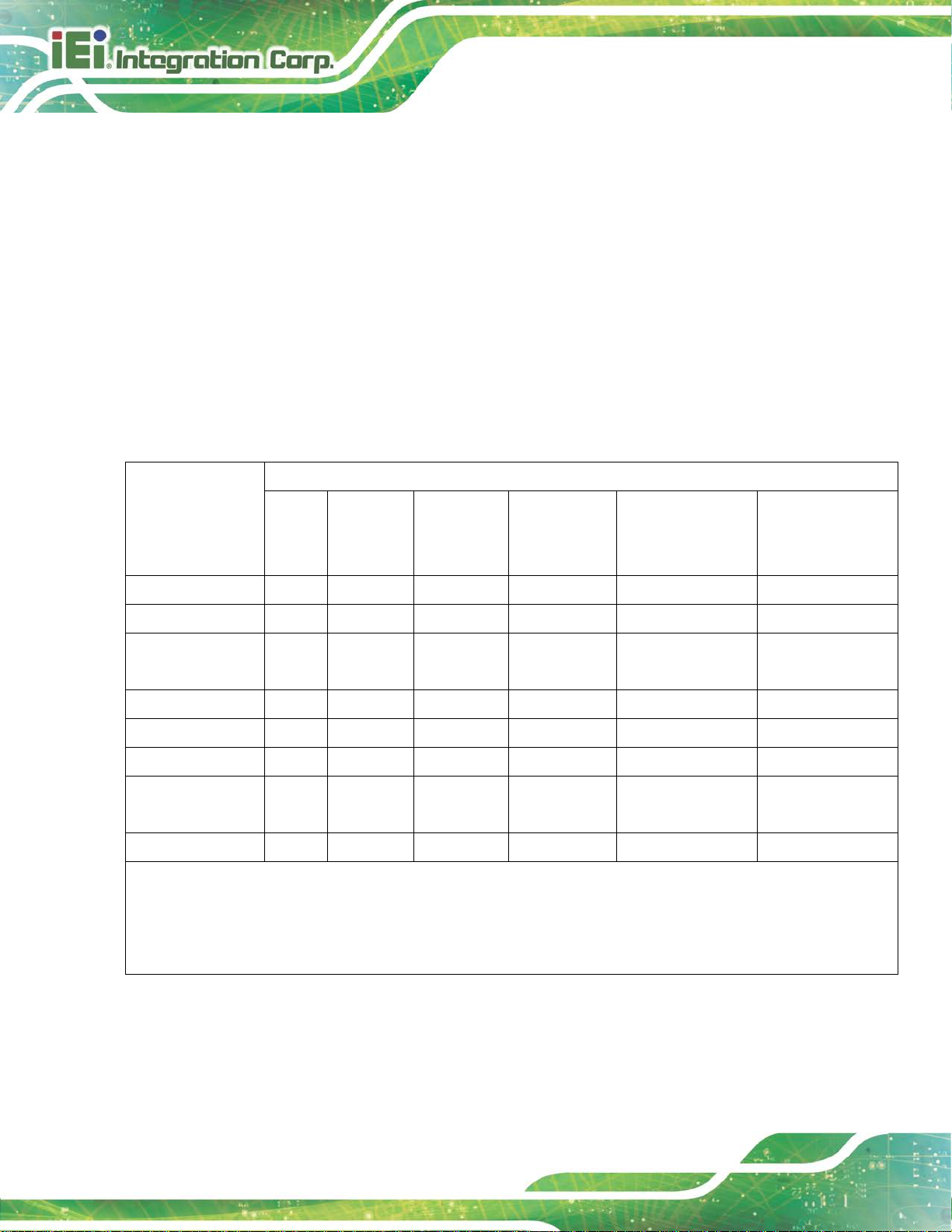
The details provided in this appendix are to ensure that the product is compliant with the
Peoples Republic of China (China) RoHS standards. The table below acknowledges the
presences of small quantities of certain material s in the product, and is applicable t o China
RoHS only.
A label will be placed on each product to indicate the estimated “Environmentally Friendly
Use Period” (EFUP). This is an estimate of the number of years that these substances
would “not leak out or undergo abrupt change.” This product may contain replaceable
sub-assemblies/components which have a shorter EFUP such as batteries and lamps.
These components will be separately marked.
Please refer to the following table.
Part Name Toxic or Hazardous Substances and Elements
Lead
(Pb)
Housing
Display
Printed Circuit
Board
Metal Fasteners
Cable Assembly
Fan Assembly
Power Supply
Assemblies
Battery
O: This toxic or hazardous substance is contained in all of the homogeneous materials for the part is below the lim it
requirement in SJ/T11363-2006 (now replaced by GB/T 26572-2011).
X: This toxic or hazardou s substance is contained in at least one of the ho mogeneous materials for this part is above
O O O O O O
O O O O O O
O O O O O O
O O O O O O
O O O O O O
O O O O O O
O O O O O O
O O O O O O
Mercury
(Hg)
Cadmium
(Cd)
Hexavalent
Chromium
(CR(VI))
Polybrominated
Biphenyls
(PBB)
Polybrominated
Diphenyl Ethers
(PBDE)
the limit requirement in SJ/T11363-2006 (now replaced by GB/T 26572-2011).
Page 75
HYPER-RK39 SBC
Page 65
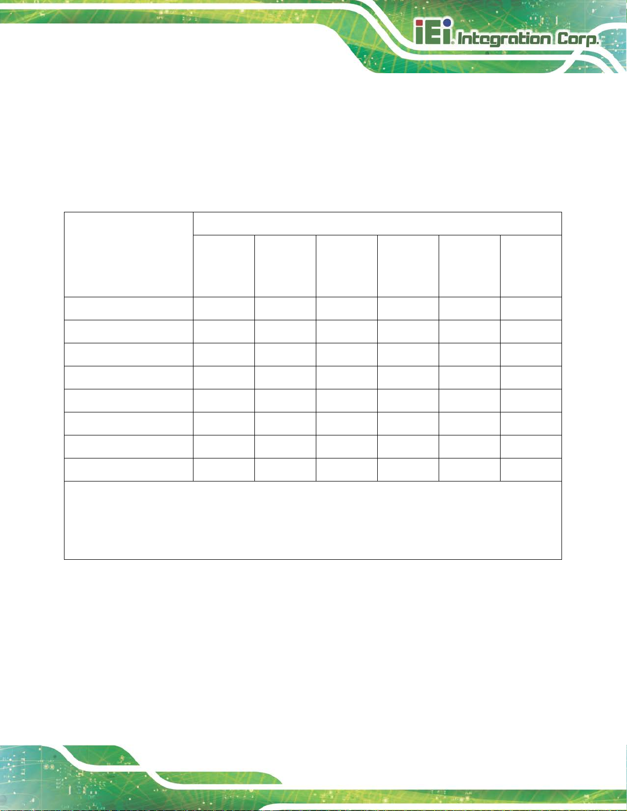
部件名称
有毒有害物质或元素
铅
汞
镉
六价铬
多溴联苯
多溴二苯
醚
壳体
显示
印刷电路板
金属螺帽
电缆组装
风扇组装
电力供应组装
电池
此附件旨在确保本产品符合中国 RoHS 标准。以下表格标示此产品中某有毒物质的含量符
合中国 RoHS 标准规定的限量要求。
本产品上会附有”环境友好使用期限”的标签,此期限是估算这些物质”不会有泄漏或突变”的
年限。本产品可能包含有较短的环境友好使用期限的可替换元件,像是电池或灯管,这些元
件将会单独标示出来。
(Pb)
O: 表示该有毒有害物质在该部件所有物质材料中的含量均在 SJ/T 11363-2006 (现由 GB/T 26572-2011 取代)
标准规定的限量要求以下。
O O O O O O
O O O O O O
O O O O O O
O O O O O O
O O O O O O
O O O O O O
O O O O O O
O O O O O O
(Hg)
(Cd)
(CR(VI))
(PBB)
(PBDE)
X: 表示该有毒有害物质至少在该部件的某一均质材料中的含量超出 SJ/T 11363-2006 (现由 GB/T
26572-2011 取代) 标准规定的限量要求。
 Loading...