

Page 1

HYPER-BW
Page I
HYP E R-BW
MODEL:
Re v. 1.02 - 13 December, 2017
P ICO-ITX SBC supports Intel® 14nm Pentium®/Celeron® on-board SoC,
d u a l Min i HDMI, M.2 2242, GbE, USB 3.0, S ATA 6Gb/s , COM,
Audio and RoHS
User Manual
Page 2

HYPER-BW
Page II
Re vis ion
Date Version Changes
13 December, 2017 1.02 Updated Section 1.5: Dimensions
6 July, 2017 1.01 Updated Section 1.2: Model Variations
Updated Section 1.7: Technical Specifications
27 June, 2016 1.00 Initial release
Page 3

HYPER-BW
Page III
Copyright
COPYRIGHT NOTICE
The information in this document is subject to change without prior notice in order to
improve reliability, design and function and does not represent a commitment on the part
of the manufacturer.
In no event will the manufacturer be liable for direct, indirect, special, incidental, or
consequential damages arising out of the use or inability to use the product or
documentation, even if advised of the possibility of such damages.
This document contains proprietary information protected by copyright. All rights are
reserved. No part of this manual may be reproduced by any mechanical, electronic, or
other means in any form without prior written permission of the manufacturer.
TR ADEMARKS
All registered trademarks and product names mentioned herein are used for identification
purposes only and may be trademarks and/or registered trademarks of their respective
owners.
Page 4

HYPER-BW
Page IV
Manual Conventions
WARNING
Warnings appear where overlooked details may cause damage to the
equipment or result in personal injury. Warnings should be taken
seriously.
C AUTIO N
Cautionary messages should be heeded to help reduce the chance of
losing data or damaging the product.
NOTE
These messages inform the reader of essential but non-critical
information. These messages should be read carefully as any directions
or instructions contained therein can help avoid making mistakes.
HOT SURFACE
This symbol indicates a hot surface that should not be touched without
taking care.
Page 5

HYPER-BW
Page V
Table of Contents
1 INTRODUCTION .......................................................................................................... 1
1.1 INTRODUCTION ........................................................................................................... 2
1.2 MODEL VARIATIONS ................................................................................................... 2
1.3 FEATURES ................................................................................................................... 3
1.4 CONNECTORS ............................................................................................................. 4
1.5 DIMENSIONS ............................................................................................................... 6
1.6 DATA FLOW ................................................................................................................ 8
1.7 TECHNICAL SPECIFICATIONS ...................................................................................... 9
2 UNPACKING ................................................................................................................ 11
2.1 ANTI-STATIC PRECAUTIONS ...................................................................................... 12
2.2 UNPACKING PRECAUTIONS ....................................................................................... 12
2.3 PACKING LIST ........................................................................................................... 13
2.4 OPTIONAL ITEMS ...................................................................................................... 14
3 CONNECTORS ........................................................................................................... 15
3.1 PERIPHERAL INTERFACE CONNECTORS ..................................................................... 16
3.1.1 HYPER-BW Layout .......................................................................................... 16
3.1.2 Peripheral Interface Connectors ..................................................................... 17
3.1.3 External Interface Panel Connectors ............................................................... 18
3.2 INTERNAL PERIPHERAL CONNECTORS ...................................................................... 18
3.2.1 AT/ATX Mode Select Switch ............................................................................. 18
3.2.2 Audio Connector .............................................................................................. 19
3.2.3 Battery Connector ............................................................................................ 20
3.2.4 BIOS FW Connector ........................................................................................ 21
3.2.5 Buzzer Connector ............................................................................................. 21
3.2.6 Clear CMOS Button ......................................................................................... 22
3.2.7 CPU Fan Connector ........................................................................................ 23
3.2.8 DDR3L SO-DIMM Slot .................................................................................... 24
3.2.9 Debug Connector ............................................................................................. 24
3.2.10 EC FW Connector .......................................................................................... 25
Page 6

HYPER-BW
Page VI
3.2.11 Front Panel Connector ................................................................................... 26
3.2.12 LAN LED Connector ...................................................................................... 27
3.2.13 M.2 2242 (B key) Socket ................................................................................ 28
3.2.14 RS-232 Serial Port Connector ....................................................................... 28
3.2.15 SATA 6Gb/s Drive Connector ........................................................................ 29
3.2.16 SATA Power Connector .................................................................................. 30
3.2.17 SMBus Connector .......................................................................................... 31
3.2.18 USB Connector .............................................................................................. 31
3.3 EXTERNAL PERIPHERAL INTERFACE CONNECTOR PANEL ......................................... 32
3.3.1 HDMI Connectors ............................................................................................ 33
3.3.2 LAN Connector ................................................................................................ 34
3.3.3 Power Connector ............................................................................................. 34
3.3.4 USB Connectors ............................................................................................... 35
4 INSTALLATION ......................................................................................................... 36
4.1 ANTI-STATIC PRECAUTIONS ...................................................................................... 37
4.2 INSTALLATION CONSIDERATIONS .............................................................................. 37
4.3 SO-DIMM INSTALLATION ....................................................................................... 39
4.4 INTERNAL PERIPHERAL DEVICE CONNECTIONS ........................................................ 40
4.4.1 SATA Drive Connection ................................................................................... 40
4.4.2 Single RS-232 Cable ........................................................................................ 41
4.5 HEAT SINK ENCLOSURE ............................................................................................ 42
5 BIOS .............................................................................................................................. 43
5.1 INTRODUCTION ......................................................................................................... 44
5.1.1 Starting Setup ................................................................................................... 44
5.1.2 Using Setup ...................................................................................................... 44
5.1.3 Getting Help ..................................................................................................... 45
5.1.4 Unable to Reboot after Configuration Changes .............................................. 45
5.1.5 BIOS Menu Bar ................................................................................................ 45
5.2 MAIN ........................................................................................................................ 46
5.3 ADVANCED ............................................................................................................... 47
5.3.1 ACPI Settings ................................................................................................... 48
5.3.2 IT8528 Super IO Configuration ....................................................................... 49
5.3.2.1 Serial Port 1 Configuration ....................................................................... 49
Page 7

HYPER-BW
Page VII
5.3.3 iWDD H/W Monitor ......................................................................................... 51
5.3.3.1 Smart Fan Mode Configuration ................................................................ 52
5.3.4 RTC Wake Settings ........................................................................................... 55
5.3.5 Serial Port Console Redirection ...................................................................... 56
5.3.5.1 Console Redirection Settings .................................................................... 57
5.3.6 iEi Feature ....................................................................................................... 59
5.3.7 CPU Configuration .......................................................................................... 60
5.3.8 SATA Configuration ......................................................................................... 61
5.3.9 USB Configuration ........................................................................................... 62
5.4 CHIPSET ................................................................................................................... 63
5.4.1 North Bridge Configuration ............................................................................. 64
5.4.1.1 Intel IGD Configuration ............................................................................ 64
5.4.2 Southbridge Configuration .............................................................................. 67
5.4.2.1 PCI Express Configuration ....................................................................... 68
5.4.2.2 M.2 Socket PCIEx1 .................................................................................. 69
5.5 SECURITY ................................................................................................................. 70
5.6 BOOT ........................................................................................................................ 71
5.7 EXIT ......................................................................................................................... 73
A REGULATORY COMPLIANCE .............................................................................. 75
B PRODUCT DISPOSAL .............................................................................................. 77
C BIOS OPTIONS .......................................................................................................... 79
D TERMINOLOGY ....................................................................................................... 82
E WATCHDOG TIMER ................................................................................................. 86
F HAZARDOUS MATERIALS DISCLOSURE .......................................................... 89
Page 8

HYPER-BW
Page VIII
Lis t o f Figu re s
Figure 1-1: HYPER-BW ................................................................................................................... 2
Figure 1-2: Connectors (Front Side)
Figure 1-3: Connectors (Solder Side)
Figure 1-4: Dimensions (mm)
Figure 1-5: Data Flow Diagram
Figure 3-1: Connector and Jumper Locations (Front)
Figure 3-2: Connector and Jumper Locations (Rear)
Figure 3-3: AT/ATX Mode Select Switch Location
Figure 3-4: Audio Connector Location
Figure 3-5: Battery Connector Location
Figure 3-6: BIOS FW Connector Location
Figure 3-7: Buzzer Connector Location
Figure 3-8: Clear CMOS Button Location
Figure 3-9: CPU Fan Connector Location
Figure 3-10: DDR3L SO-DIMM Slot Location
Figure 3-11: Debug Port Connector Location
Figure 3-12: EC FW Connector Location
Figure 3-13: Front Panel Connector Location
............................................................................................. 4
........................................................................................... 5
........................................................................................................ 7
...................................................................................................... 8
..............................................................16
...............................................................16
....................................................................19
.......................................................................................19
.....................................................................................20
..................................................................................21
.....................................................................................22
...................................................................................23
..................................................................................23
.............................................................................24
............................................................................25
....................................................................................26
...........................................................................26
Figure 3-14: LAN LED Connector Locations
Figure 3-15: M.2 2242 (B key) Socket Location
Figure 3-16: RS-232 Serial Port Connector Location
Figure 3-17: SATA 6Gb/s Drive Connector Location ................................................................30
Figure 3-18: SATA Power Connector Location
Figure 3-19: SMBus Connector Location
Figure 3-20: USB Connector Location
Figure 3-21: External Peripheral Interface Connector
Figure 3-22: HDMI Connector
Figure 3-23: LAN Connector
Figure 4-1: SO-DIMM Installation
Figure 4-2: SATA Drive Cable Connection
Figure 4-3: Single RS-232 Cable Installation
.............................................................................27
.........................................................................28
................................................................29
.........................................................................30
...................................................................................31
........................................................................................32
..............................................................33
......................................................................................................33
........................................................................................................34
................................................................................................39
.................................................................................40
.............................................................................41
Page 9

HYPER-BW
Page IX
Figure 4-4: Heat Sink Retention Screws .....................................................................................42
Page 10

HYPER-BW
Page X
Lis t o f Ta ble s
Table 1-1: HYPER-BW Model Variations ...................................................................................... 2
Table 1-2: Technical Specifications
Table 3-1: Peripheral Interface Connectors
Table 3-2: Rear Panel Connectors
Table 3-3: AT/ATX Mode Select Switch Settings
Table 3-4: Audio Connector Pinouts
Table 3-5: Battery Connector Pinouts
Table 3-6: BIOS FW Connector Pinouts
Table 3-7: Buzzer Connector Pinouts
Table 3-8: Clear CMOS Button Settings
Table 3-9: CPU Fan Connector Pinouts
Table 3-10: Debug Port Connector Pinouts
Table 3-11: EC FW Connector Pinouts
Table 3-12: Front Panel Connector Pinouts
Table 3-13: LAN LED Connector Pinouts
Table 3-14: RS-232 Serial Port Connector Pinouts
Table 3-15: SATA Power Connector Pinouts
Table 3-16: SMBus Connector Pinouts
............................................................................................10
...............................................................................17
..............................................................................................18
.......................................................................18
..........................................................................................20
........................................................................................20
.....................................................................................21
.........................................................................................22
.....................................................................................22
.....................................................................................23
...............................................................................25
.......................................................................................26
...............................................................................27
...................................................................................27
...................................................................29
.............................................................................30
......................................................................................31
Table 3-17: USB Connector Pinouts
Table 3-18: HDMI Connector Pinouts
Table 3-19: LAN Pinouts
Table 3-20: Connector LEDs
Table 3-21: Power Connector Pinouts
Table 3-22: USB 2.0 & USB 3.0 Port Pinouts
Table 5-1: BIOS Navigation Keys
...........................................................................................32
.........................................................................................33
..............................................................................................................34
........................................................................................................34
........................................................................................35
.............................................................................35
................................................................................................45
Page 11

HYPER-BW
Page XI
BIO S Me n u s
BIOS Menu 1: Main .......................................................................................................................46
BIOS Menu 2: Advanced
BIOS Menu 3: ACPI Configuration
BIOS Menu 4: Super IO Configuration
BIOS Menu 5: Serial Port 1 Configuration Menu
BIOS Menu 6: Hardware Monitor
BIOS Menu 7: Smart Fan Mode Configuration
BIOS Menu 8: RTC Wake Settings
BIOS Menu 9: Serial Port Console Redirection
BIOS Menu 10: Console Redirection Settings
BIOS Menu 11: IEI Feature
BIOS Menu 12: CPU Configuration
BIOS Menu 13: IDE
BIOS Menu 14: USB Configuration
BIOS Menu 15: Chipset
BIOS Menu 16: Northbridge Chipset Configuration
BIOS Menu 17: Integrated Graphics
BIOS Menu 18: Southbridge Chipset Configuration
Configuration ...............................................................................................61
..............................................................................................................47
..............................................................................................48
........................................................................................49
.......................................................................49
.................................................................................................51
..........................................................................52
..............................................................................................55
.........................................................................56
...........................................................................57
...........................................................................................................59
.............................................................................................60
.............................................................................................62
................................................................................................................63
..................................................................64
...........................................................................................65
.................................................................67
BIOS Menu 19: PCI Express Configuration
BIOS Menu 20: PCI Express Configuration
BIOS Menu 21: Security
BIOS Menu 22: Boot
BIOS Menu 23:Exit
...............................................................................68
...............................................................................69
...............................................................................................................70
.....................................................................................................................71
........................................................................................................................73
Page 12

HYPER-BW
Page 1
Chapter
1
1 Introduction
Page 13

HYPER-BW
Page 2
1.1 Introduction
Figure 1-1: HYPER-BW
The HYPER-BW is a PICO-ITX motherboard. It accepts an Intel® Pentium®/Celeron®
on-board SoC and supports one 204-pin 1333/1600 MHz single-channel DDR3L SDRAM
unbuffered SO-DIMM module up to 8 GB.
The HYPER-BW includes two mini HDMI ports. Expansion and I/O include one USB 2.0
connector and one USB 3.0 connector on the rear panel, two USB 2.0 connectors by pin
header and one SATA 6Gb/s connector. Serial device connectivity is provided by one
internal RS-232 connector. One RJ-45 Ethernet connector provides the system with
smooth connections to an external LAN.
1.2 Model Variations
The model variations of the HYPER-BW Series are listed below.
Model No. SoC
HYPER-BW-N4
HYPER-BW-N3
HYPER-BW-N2
HYPER-BW-N1
HYPER-BW-E8-ECO
Intel® Pentium® 14nm quad-core N3710 up to 2.56GHz (6W)
Intel® Celeron® 14nm quad-core N3160 up to 2.24GHz (6W)
Intel® Celeron® 14nm dual-core N3060 up to 2.48GHz (6W)
Intel® Celeron® 14nm dual-core N3010 up to 2.24GHz (4W)
Intel® Celeron® 14nm quad-core x5-E8000 up to 2.00GHz (5W)
Table 1-1: HYPER-BW Model Variations
Page 14

HYPER-BW
Page 3
1.3 Features
Some of the HYPER-BW motherboard features are listed below:
Pico-ITX SBC supports Intel® 14nm Pentium®/Celeron® on-board SoC
IEI jumper-less function
Dual independent display support
1333/1600 MHz 1.35V DDR3L SDRAM up to 8 GB supported
COM, USB 3.0, SATA 6Gb/s and Audio support
1 x M.2 2242 B key slot for expansion possibility
IEI One Key Recovery solution allows you to create rapid OS backup and
recovery
Page 15

HYPER-BW
Page 4
1.4 Connectors
The connectors on the HYPER-BW are shown in the figure below.
Figure 1-2: Connectors (Front Side)
Page 16

HYPER-BW
Page 5
Figure 1-3: Connectors (Solder Side)
Page 17
HYPER-BW
Page 6
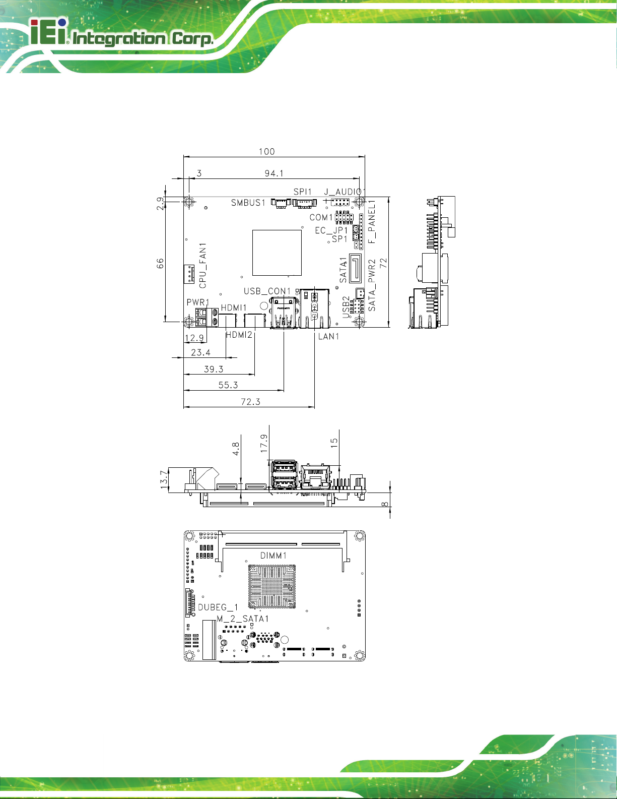
1.5 Dimensions
The dimensions of the board are listed below:
Page 18

HYPER-BW
Page 7
Figure 1-4: Dimensions (mm)
Page 19

HYPER-BW
Page 8
1.6 Data Flow
Figure 1-5 shows the data flow between the system chipset, the CPU and other
components installed on the motherboard.
Figure 1-5: Data Flow Diagram
Page 20

HYPER-BW
Page 9
1.7 Technical Specifications
HYPER-BW technical specifications are listed below.
Specification HYP ER -BW
SoC
BIO S
Me m o ry
Graphics
Intel® Pentium® N3710 on-board SoC (up to 2.56GHz,
quad-core, 2MB cache, TDP=6W)
Intel® Celeron® N3160 on-board SoC (up to 2.24GHz,
quad-core, 2MB cache, TDP=6W)
Intel® Celeron® N3060 on-board SoC (up to 2.48GHz,
dual-core, 2MB cache, TDP=6W)
Intel® Celeron® N3010 on-board SoC (up to 2.24GHz,
dual-core, 2MB cache, TDP=4W)
Intel® Celeron® x5-E8000 on-board SoC (up to 2.00GHz,
quad-core, 2MB cache, TDP=5W)
AMI UEFI BIOS
One 204-pin 1333/1600 MHz single-channel DDR3L SDRAM
unbuffered SO-DIMM slot support up to 8 GB
Intel® HD Graphics Gen 8 Engine with 16 low-power
execution units, supporting DX11.1, OpenGL 4.2 and
OpenCL1.2
Display Output
Ethernet
EC IT8587
Watchdog Timer
I/O In te r f a c e
Audio Connector
Ethernet
Se r ia l Po r ts
Dual independent display
2 x Mini HDMI (up to 3840x2160@30Hz)
LAN1: Realtek RTL8111 controller
Software programmable support 1~255 sec. system reset
1 x HD Audio by 10-pin (2x5) header
One RJ-45 port
1 x RS-232 (by pin header)
Page 21

HYPER-BW
Page 10
Specification HYP ER -BW
USB P orts
Front Panel
LAN LED
FAN
Expansion
Storage
Se r ia l ATA
Environmental and Power Specifications
Power Supply
1 x USB 3.0 (on rear I/O)
3 x USB 2.0 (1 on rear I/O, 2 by pin header)
1 x Front panel (1x10 pin, power LED, HDD LED, power
button, reset button)
1 x 2-pin (1x2) header
1 x Smart fan connector (1x4 pin)
1 x M.2 2242 (B Key)
1 x SATA 6G/s with 5V SATA power connector (No RAID)
(SATA port0)
12V DC input only
1 x Power terminal block (1x2 pin)
Support AT/ AT X m od e
Power Consumption
Operating Temperature
Storage Temperature
Hu m idity
Vibra tio n
Physical Specifications
Dim e nsions
We ig ht GW/NW
Table 1-2: Technical Specifications
12V@1.52A (Intel® Pentium® processor N3710 with 8 GB
1600 MHz DDR3L memory)
-20°C ~ 60°C
-30°C ~ 70°C
5% ~ 95%, non-condensing
3G
100 mm x 72 mm
600 g / 250 g
Page 22

HYPER-BW
Page 11
Chapter
2
2 Unpacking
Page 23

HYPER-BW
Page 12
2.1 An ti-static Precautions
WARNING!
Static electricity can destroy certain electronics. Make sure to follow the
ESD precautions to prevent damage to the product, and injury to the
user.
Make sure to adhere to the following guidelines:
Wear an anti-static wristband: Wearing an anti-static wristband can prevent
electrostatic discharge.
Self-grounding: Touch a grounded conductor every few minutes to discharge
any excess static buildup.
Use an anti-static pad: When configuring any circuit board, place it on an
anti-static mat.
Only handle the edges of the PCB: Don't touch the surface of the
motherboard. Hold the motherboard by the edges when handling.
2.2 Unpacking Precautions
When the HYPER-BW is unpacked, please do the following:
Follow the antistatic guidelines above.
Make sure the packing box is facing upwards when opening.
Make sure all the packing list items are present.
Page 24

HYPER-BW
Page 13
2.3 P a c kin g Lis t
NOTE:
If any of the components listed in the checklist below are missing, do not
proceed with the installation. Contact the IEI reseller or vendor the
HYPER-BW was purchased from or contact an IEI sales representative
directly by sending an email to
The HYPER-BW is shipped with the following components:
Quantity Item and Part Number Im a g e
1 1 x HYPER-BW single board computer with
specific heat sink
1 SATA with power cable kit
(P/N: 32801-000201-300-RS)
1 RS-232 cable
sales@iei.com.tw.
(P/N: 32205-002700-200-RS)
1 Utility CD
1 One Key Recovery CD
 Loading...