

Page 1

HYPER-AL SBC
Page I
HYPER-AL
MODEL:
Pico-ITX SBC with 14nm Intel® Celeron® N3350 SoC,
Rev. 1.01 - September 10, 2018
HYPER-AL CPU Card
HDMI, LVDS, Dual PCIe GbE, USB 3.0, M.2 Slots,
SATA 6Gb/s, RS-232, HD Audio and RoHS
User Manual
Page 2

HYPER-AL SBC
Page II
Revision
Date Version Changes
September 10, 2018 1.01 Modify Section 3.2.2: LVDS LCD Connector
June 8, 2018 1.00 Initial release
Page 3

HYPER-AL SBC
Page III
Copyright
COPYRIGHT NOTICE
The information in this document is subject to change without prior notice in order to
improve reliability, design and function and does not represent a commitment on the part
of the manufacturer.
In no event will the manufacturer be liable for direct, indirect, special, incidental, or
consequential damages arising out of the use or inability to use the product or
documentation, even if advised of the possibil ity of such damages.
This document contains proprietary information protected by copyright. All rights are
reserved. No part of this manual may be reproduced by any mechanical, electronic, or
other means in any form without prior written permission of the manufacturer.
TRADEMARKS
All registered trademarks and product names mentioned herein are used for identification
purposes only and may be trademarks and/or registered trademarks of their respective
owners.
Page 4

HYPER-AL SBC
Page IV
Manual Conventions
WARNING
Warnings appear where overlooked details may cause damage to the
equipment or result in personal injury. Warnings should be taken
seriously.
CAUTION
Cautionary messages should be heeded to help red uce the chance of
losing data or damaging the product.
NOTE
These messages inform the reader of essent ial but non-critical
information. These messages should be read carefully as any directions
or instructions contained therein can help avoid making mistakes.
Page 5

HYPER-AL SBC
Page V
Table of Contents
1 INTRODUCTION .......................................................................................................... 1
1.1 INTRODUCTION ........................................................................................................... 2
1.2 FEATURES ................................................................................................................... 3
1.3 CONNECTORS ............................................................................................................. 4
1.4 DIMENSIONS ............................................................................................................... 5
1.5 DATA FLOW ................................................................................................................ 6
1.6 TECHNICAL SPECIFICATIONS ...................................................................................... 7
2 UNPACKING ................................................................................................................. 9
2.1 ANTI-STATIC PRECAUTIONS ...................................................................................... 10
2.2 UNPACKING PRECAUTIONS ....................................................................................... 10
2.3 PACKING LIST ............................................................................................................ 11
2.4 OPTIONAL ITEMS ...................................................................................................... 12
3 CONNECTORS ........................................................................................................... 13
3.1 PERIPHERAL INTERFACE CONNECTORS ..................................................................... 14
3.1.1 HYPER-AL Layout ........................................................................................... 14
3.1.2 Peripheral Interface Connectors ..................................................................... 15
3.1.3 External Interface Panel Connectors ............................................................... 16
3.2 INTERNAL PERIPHERAL CONNECTORS ...................................................................... 16
3.2.1 Audio Connector .............................................................................................. 16
3.2.2 Battery Connector ............................................................................................ 17
3.2.1 Buzzer Connector ............................................................................................. 18
3.2.2 DDR3L SO-DIMM Socket ................................................................................ 19
3.2.3 Digital I/O Connector ...................................................................................... 20
3.2.1 Front Panel Connector .................................................................................... 21
3.2.2 LVDS LCD Connector ..................................................................................... 22
3.2.3 LVDS Backlight Inverter Connector ................................................................ 23
3.2.4 M.2 Slot, A-key ................................................................................................. 24
3.2.1 M.2 Slot, B-key ................................................................................................. 26
3.2.2 RS-232 Serial Port Connector ......................................................................... 28
Page 6

HYPER-AL SBC
Page VI
3.2.3 SATA 6Gb/s Connector..................................................................................... 29
3.2.4 SATA Power Connector .................................................................................... 29
3.2.5 SPI Flash Connector ........................................................................................ 30
3.2.6 USB 2.0 Connector .......................................................................................... 31
3.3 EXTERNAL PERIPHERAL INTERFACE CONNECTOR PANEL ......................................... 32
3.3.1 HDMI Connector ............................................................................................. 32
3.3.2 LAN Connectors ............................................................................................... 33
3.3.3 USB 3.0 Connectors ......................................................................................... 34
3.3.1 Power Connector (Power Adapter) ................................................................. 35
4 INSTALLATION ......................................................................................................... 36
4.1 ANTI-STATIC PRECAUTIONS ...................................................................................... 37
4.2 INSTALLATION CONSIDERATIONS .............................................................................. 37
4.3 SO-DIMM INSTALLATION ....................................................................................... 39
4.4 M.2 MODULE INSTALLATION .................................................................................... 39
4.5 SYSTEM CONFIGURATION ......................................................................................... 41
4.5.1 AT/A TX Mode Select Switch ............................................................................. 41
4.5.1 LVDS Voltage Selection ................................................................................... 42
4.6 CHASSIS INSTALLATION ............................................................................................ 43
4.6.1 Airflow .............................................................................................................. 43
4.6.2 Heat Spreader Installation ............................................................................... 43
4.6.3 Motherboard Installation ................................................................................. 43
4.7 INTERNAL PERIPHERAL DEVICE CONNECTIONS ........................................................ 44
4.7.1 SATA Drive Connection ................................................................................... 44
5 BIOS .............................................................................................................................. 46
5.1 INTRODUCTION ......................................................................................................... 47
5.1.1 Starting Setup ................................................................................................... 47
5.1.2 Using Setup ...................................................................................................... 47
5.1.3 Getting Help ..................................................................................................... 48
5.1.4 Unable to Reboot after Configuration Changes .............................................. 48
5.1.5 BIOS Menu Bar ................................................................................................ 48
5.2 MAIN ........................................................................................................................ 49
5.3 ADVANCED ............................................................................................................... 50
5.3.1 ACPI Settings ................................................................................................... 51
Page 7

HYPER-AL SBC
Page VII
5.3.2 iWDD H/W Monitor ......................................................................................... 52
5.3.3 iWDD Super IO Configuration ........................................................................ 53
5.3.3.1 Serial Port 1 Configuration ....................................................................... 53
5.3.4 USB Configuration ........................................................................................... 55
5.3.5 CPU Configuration .......................................................................................... 56
5.3.6 RTC Wake Settings ........................................................................................... 58
5.3.7 Power Saving Configuration ............................................................................ 59
5.3.8 Serial Port Console Redirection ...................................................................... 60
5.3.8.1 Legacy Console Redirection Settings ....................................................... 61
5.3.9 IEI Feature ....................................................................................................... 62
5.4 CHIPSET ................................................................................................................... 63
5.4.1 North Bridge Configuration ............................................................................. 64
5.4.1.1 Intel IGD Configuration ............................................................................ 64
5.4.1.2 LCD Control ............................................................................................. 66
5.4.2 South Bridge Configuration ............................................................................. 68
5.4.2.1 HD-Audio Configuration .......................................................................... 69
5.4.2.2 PCI Express Configuration ....................................................................... 70
5.4.2.2.1 M2_CN1 ............................................................................................ 71
5.4.2.3 SATA Configuration .................................................................................. 72
5.5 SECURITY ................................................................................................................. 73
5.6 BOOT ........................................................................................................................ 74
5.7 SAVE & EXIT ............................................................................................................ 76
6 SOFTWARE DRIVERS .............................................................................................. 78
6.1 AVAILABLE DRIVERS ................................................................................................ 79
6.2 DRIVER DOWNLOAD ................................................................................................ 79
A REGULATORY COMPLIANCE .............................................................................. 82
B PRODUCT DISPOSAL .............................................................................................. 84
C BIOS MENU OPTIONS ............................................................................................. 86
D DIGITAL I/O INTERFACE ....................................................................................... 89
E WA TCHDOG TIMER ................................................................................................. 92
F HAZARDOUS MATERIALS DISCLOSU RE .......................................................... 95
Page 8

HYPER-AL SBC
Page VIII
List of Figures
Figure 1-1: HYPER-AL .................................................................................................................... 2
Figure 1-2: Connectors (Front Side) ............................................................................................. 4
Figure 1-3: Connectors (Solder Side) ........................................................................................... 4
Figure 1-4: Dimensions with Heat Spreader (mm) ...................................................................... 5
Figure 1-5: Data Flow Diagram ...................................................................................................... 6
Figure 3-1: Connector and Jumper Locations (Front Side) ..................................................... 14
Figure 3-2: Connector and Jumper Locations (Solder Side) ................................................... 14
Figure 3-3: Audio Connector Location ....................................................................................... 16
Figure 3-4: Battery Connector Location ..................................................................................... 18
Figure 3-5: Buzzer Connector Location ..................................................................................... 19
Figure 3-6: DDR3L SO-DIMM Socket Location .......................................................................... 19
Figure 3-7: Digital I/O Connector Location ................................................................................ 20
Figure 3-8: Front Panel Connector Location ............................................................................. 21
Figure 3-9: LVDS Connector Location ........................................................................................ 22
Figure 3-10: Backlight Inverter Connector Location ................................................................. 23
Figure 3-11: M.2 A-key Slot Location .......................................................................................... 24
Figure 3-12: M.2 B-key Slot Location .......................................................................................... 26
Figure 3-13: RS-232 Serial Port Connector Location ................................................................ 28
Figure 3-14: SATA 6Gb/s Connector Location .......................................................................... 29
Figure 3-15: SATA Power Connector Location ......................................................................... 30
Figure 3-16: SPI Flash Connector Location ............................................................................... 30
Figure 3-17: USB Connector Location ........................................................................................ 31
Figure 3-18: External Peripheral Interface Conn ector .............................................................. 32
Figure 3-19: HDMI Connector ...................................................................................................... 33
Figure 3-20: LAN Connector ........................................................................................................ 34
Figure 3-21: USB 3.0 Port Pinout Locations .............................................................................. 35
Figure 3-22: Power Input Connector ........................................................................................... 35
Figure 4-1: SO-DIMM Installation ................................................................................................ 39
Figure 4-2: Inserting the M.2 Module into the Slot at an Angle ............................................... 40
Figure 4-3: Securing the M.2 Module .......................................................................................... 40
Figure 4-4: AT/ATX Mode Select Switch Location .................................................................... 41
Page 9

HYPER-AL SBC
Page IX
Figure 4-5: LVDS Voltage Selection Jumper Location ............................................................. 42
Figure 4-6: SATA Drive Cable Connection ................................................................................. 45
Figure 6-1: IEI Resource Download Center ................................................................................ 79
Page 10

HYPER-AL SBC
Page X
List of Tables
Table 1-1: Technical Specifications .............................................................................................. 8
Table 3-1: Peripheral Interface Connectors ............................................................................... 15
Table 3-2: Rear Panel Connectors .............................................................................................. 16
Table 3-3: Audio Connector Pinouts .......................................................................................... 17
Table 3-4: Battery Connector Pinouts ........................................................................................ 18
Table 3-5: Buzzer Connector Pinouts ......................................................................................... 19
Table 3-6: Digital I/O Connector Pinouts .................................................................................... 20
Table 3-7: Front Panel Connector Pinouts ................................................................................. 21
Table 3-8: LVDS Connector Pinouts ........................................................................................... 23
Table 3-9: Backlight Inverter Connector Pinouts ...................................................................... 24
Table 3-10: M.2 A-Key Slot Pinouts ............................................................................................ 26
Table 3-11: M.2 B-Key Slot Pinouts ............................................................................................ 27
Table 3-12: RS-232 Serial Port Connector Pinouts ................................................................... 28
Table 3-13: SATA Power Connector Pinouts ............................................................................. 30
Table 3-14: SPI Flash Connector Pinouts .................................................................................. 31
Table 3-15: USB Connector Pinouts ........................................................................................... 31
Table 3-16: HDMI Connector Pinouts ......................................................................................... 33
Table 3-17: LAN Pinouts .............................................................................................................. 33
Table 3-18: USB 3.0 Port Pinouts ................................................................................................ 34
Table 4-1: AT/ATX Mode Select Switch Settings ....................................................................... 41
Table 4-2: LVDS Voltage Selection Jumper Settings ................................................................ 42
Table 5-1: BIOS Navigation Keys ................................................................................................ 48
Page 11

HYPER-AL SBC
Page XI
List of BIOS Menus
BIOS Menu 1: Main ....................................................................................................................... 49
BIOS Menu 2: Advanced .............................................................................................................. 50
BIOS Menu 3: ACPI Settings ....................................................................................................... 51
BIOS Menu 4: iWDD H/W Monitor ............................................................................................... 52
BIOS Menu 5: iWDD Super IO Configuration ............................................................................. 53
BIOS Menu 6: Serial Port 1 Configuration ................................................................................. 53
BIOS Menu 7: USB Configuration ............................................................................................... 55
BIOS Menu 8: CPU Configuration ............................................................................................... 56
BIOS Menu 9: RTC Wake Settings .............................................................................................. 58
BIOS Menu 10: Power Saving Configuration ............................................................................. 59
BIOS Menu 11: Serial Port Console Redirection ....................................................................... 60
BIOS Menu 12: Legacy Console Redirection Settings ............................................................. 61
BIOS Menu 13: IEI Feature ........................................................................................................... 62
BIOS Menu 14: Chipset ................................................................................................................ 63
BIOS Menu 15: North Bridge Configuration .............................................................................. 64
BIOS Menu 16: Intel IGD Configuration ...................................................................................... 65
BIOS Menu 17: LCD Control ........................................................................................................ 66
BIOS Menu 18: South Bridge Configuration .............................................................................. 68
BIOS Menu 19: HD-Audio Configuration .................................................................................... 69
BIOS Menu 20: PCI Express Configuration ............................................................................... 70
BIOS Menu 21: M2_CN1 ............................................................................................................... 71
BIOS Menu 22: SATA Configuration ........................................................................................... 72
BIOS Menu 23: Security ............................................................................................................... 73
BIOS Menu 24: Boot ..................................................................................................................... 74
BIOS Menu 25: Save & Exit .......................................................................................................... 76
Page 12

Page 13

HYPER-AL SBC
Page 1
Chapter
1
1 Introduction
Page 14

HYPER-AL SBC
Page 2
1.1 Introduction
Figure 1-1: HYPER-AL
The HYPER-AL series is a single bard computer in Pico-ITX form factor. It has an
on-board 14nm Intel
1867/1600 MHz single-channel DDR3 Low Voltage (DDR3L) SDRAM SO-DIMM slot with
up to 8.0 GB of memory.
The HYPER-AL series includes one HDMI connector and one 18-bit/24-bit LVDS
connector for display. Two RJ-45 GbE connectors provide the system with smooth
connections to an external LAN.
Expansion and I/O include two M.2 slots, two USB 3.0 connectors on the rear panel, two
USB 2.0 connectors by pin header and one SATA 6Gb/s connector. Serial device
connectivity is provided by the internal RS-232 connector.
®
Celeron® N3350 processor, and supports one 204-pin
Page 15

HYPER-AL SBC
Page 3
1.2 Features
Some of the HYPER-AL motherboard features are listed below:
Pico-ITX motherboard supports 14nm Intel
HDMI and internal LVDS support independent display
One 1867/1600 MHz DDR3L SO-DIMM slot supports up to 8 GB of memory
Dual GbE LAN support
One SATA 6Gb/s connector with 5 V power output
Two USB 3.0 external connectors
Flexible expansions by M.2 A-key 2230 slot and M.2 B-key 2242 slot
One internal RS-232 connector
12 V only single voltage design for AT/ATX power by DC-IN jack
IEI One Key Recovery solution allows you to create rapid OS backup and
recovery
®
Celeron® N3350 on-board SoC
Page 16

HYPER-AL SBC
Page 4
1.3 Connectors
The connectors on the HYPER-AL are shown in the figure below.
Figure 1-2: Connectors (Front Side)
Figure 1-3: Connectors (Solder Side)
Page 17

HYPER-AL SBC
Page 5
1.4 Dimensions
The dimensions of the HYPER-AL series are listed in Figure 1-4.
Figure 1-4: Dimensions with Heat Spreader (mm)
Page 18

HYPER-AL SBC
Page 6
1.5 Data Flow
Figure 1-5 shows the data flow between the system chipset, the CPU and other
components installed on the motherboard.
ii
Figure 1-5: Data Flow Diagram
Page 19

HYPER-AL SBC
Page 7
1.6 Technical Specifications
HYPER-AL technical specifications are listed below.
Specification HYPER-AL
Form Factor Pico-ITX
SoC Intel® Celeron® N3350 on-board SoC
(up to 2.4 GHz, dual-core, 2 MB cache, TDP=6 W)
BIOS AMI UEFI BIOS
Memory
Graphics
Display Output 1 x HDMI
Ethernet Dual Realtek RTL8111H PCIe GbE controller
Digital I/O 8-bit digital I/O by 10-pin (2x5) header
Embedded Controller ITE IT8587VG
Watchdog Timer Software programmable support 1~255 sec. system reset
I/O Interface
Audio Connector 1 x Front audio by 10-pin (2x5) header
Ethernet 2 x RJ-45 GbE port
Front Panel
One 204-pin 1867/1600 MHz single-channel DDR3L SDRAM
SO-DIMM slot (system max. 8 GB)
9th generation Intel® HD Graphics with 18 execution units,
supporting 4K codec decode & encode for HEVC 4, H.264,
VP8, SVC and MVC
1 x 18-bit/24-bit single-channel LVDS
1 x Front panel by 10-pin (2x5) header
(power LED, HDD LED, power button, reset button)
Serial Ports 1 x RS-232 by 9-pin (1x9) wafer
USB Ports 2 x USB 3.0 on rear I/O
2 x USB 2.0 by 8-pin (2x4) header
Storage 1 x SATA 6Gb/s with 5 V SATA power connector
Expansion 1 x M.2 2230 slot (A key, PCIe + USB signal)
1 x M.2 2242 slot (B key, SATA + USB signal)
Page 20

HYPER-AL SBC
Page 8
Specification HYPER-AL
Environmental and Power Specifications
Power Supply 12 V DC input power (AT/ATX support)
Power Consumption
Operating Temperature -20°C ~ 60°C
Storage Temperature -10°C ~ 70°C
Humidity 5% ~ 95%, non-condensing
Physical Specifications
Dimensions 100 mm x 72 mm
Weight GW/NW 600 g / 250 g
Table 1-1: Technical Specifications
+12 V @ 2.36 A (Intel® Celeron® N3350 processor with 8 GB
1600 MHz DDR3L memory)
Page 21

HYPER-AL SBC
Page 9
Chapter
2
2 Unpacking
Page 22

HYPER-AL SBC
Page 10
2.1 Anti-static Precautions
WARNING!
Static electricity can destroy certain elect ronics. Make sur e to follow the
ESD precautions to prevent damage to the product, and injury to the
user.
Make sure to adhere to the following guidelines:
Wear an anti-static wristband: Wearing an anti-static wristband can prevent
electrostatic discharge.
Self-grounding: Touch a grounded conductor every few minutes to discharge
any excess static buildup.
Use an anti-static pad: When configuring any circuit board, place it on an
anti-static mat.
Only handle the edges of the PCB: Don't touch the surface of the
motherboard. Hold the motherboard by the edges when handling.
2.2 Unpacking Precautions
When the HYPER-AL is unpacked, please do the following:
Follow the antistatic guidelines above.
Make sure the packing box is facing upwards when opening.
Make sure all the packing list items are present .
Page 23

HYPER-AL SBC
Page 11
2.3 Packing List
NOTE:
If any of the components listed in the checklist below are missing, do not
proceed with the installation. Contact the IEI reseller or vendor the
HYPER-AL was purchased from or contact an IEI sales representative
directly by sending an email to sales@ieiworld.com
The HYPER-AL is shipped with the following components:
Quantity Item and Part Number Image
1 HYPER-AL single board computer
1 COM port cable
1 SATA and power cable
.
1 Heat spreader
4 Brass male-female spacer
(M3*20mm, thread: 6mm)
Page 24

HYPER-AL SBC
Page 12
1 Quick Installation Guide
2.4 Optional Items
The following are optional components which may be separately purchased:
Item and Part Number Image
Dual USB port cable, 210mm, p=2.0 mm
(P/N: 32001-008600-200-RS)
Audio kit, 7.1 channel
(P/N: AC-KIT-892HD-R10)
Page 25

HYPER-AL SBC
Page 13
Chapter
3
3 Connectors
Page 26

HYPER-AL SBC
Page 14
3.1 Peripheral Interface Connectors
This chapter details all the internal and external connectors.
3.1.1 HYPER-AL Layout
The figures below show all the connectors and jump ers.
Figure 3-1: Connector and Jumper Locations (Front Side)
Figure 3-2: Connector and Jumper Locations (Solder Side)
Page 27

HYPER-AL SBC
Page 15
3.1.2 Peripheral Interface Connectors
The table below lists all the connectors on the board.
Connector Type Label
Audio connector 10-pin header AUDIO1
Battery connector 2-pin wafer BT1
Buzzer connector 2-pin wafer SP1
DDR3L SO-DIMM socket 204-pin DDR3 DIMM1
Digital I/O connector 10-pin header DIO1
Front panel connector 10-pin header F_PANEL1
LVDS connector 20-pin crimp LVDS1
LVDS backlight inverter connector 6-pin wafer INV_CN1
M.2 slot, A-key M.2 A-key 2230 slot M2_CN1
M.2 slot, B-key M.2 B-key 2242 slot M2_1
RS-232 serial port connector 9-pin wafer COM1
SATA 6Gb/s connector 7-pin SATA connector SATA1
SATA power connector 2-pin wafer SATA_PWR1
SPI Flash connector 6-pin wafer JSPI1
USB 2.0 connector 8-pin header USB2-1
Table 3-1: Peripheral Interface Connectors
Page 28

HYPER-AL SBC
Page 16
3.1.3 External Interface Panel Connectors
The table below lists the connectors on the external I /O panel.
Connector Type Label
HDMI connector HDMI HDMI1
LAN connectors RJ-45 LAN1, LAN2
Power input connector Power jack CN5
USB 3.0 connectors USB 3.0 USB3-1
Table 3-2: Rear Panel Connectors
3.2 Internal Peripheral Connectors
The section describes all of the connectors on the HYPER-AL.
3.2.1 Audio Connector
CN Label:
CN Type:
CN Location:
CN Pinouts:
The audio connector is connected to external audio devices including speakers and
microphones for the input and output of audio signals to and from the system.
AUDIO1
10-pin header, p=2.00 mm
See Figure 3-3
See Table 3-3
Figure 3-3: Audio Connector Location
Page 29

HYPER-AL SBC
Page 17
Risk of explosion if battery is replaced by an incorrect type. Only
according to instructions and local
PIN NO. DESCRIPTION PIN NO. DESCRIPTION
1 SYNC 2 BCLK
3 SDO 4 SPKR
5 SDI 6 RTS
7 +V5S 8 GND
9 +V12S 10 N/A
Table 3-3: Audio Connector Pinouts
3.2.2 Battery Connector
CAUTION:
certified engineers should replace the on-board bat tery.
Dispose of used batteries
regulations.
NOTE:
It is recommended to attach the RTC battery onto the system chassis
in which the HYPER-AL is installed.
CN Label:
CN Type:
CN Location:
BT1
2-pin wafer, p=1.25 mm
See Figure 3-4
CN Pinouts:
See Table 3-4
Page 30

HYPER-AL SBC
Page 18
The battery connector is connected to the system battery. The battery provides power to
the system clock to retain the time when power is turned off.
Figure 3-4: Battery Connector Location
Pin Description
1 VBAT+
2 GND
Table 3-4: Battery Connector Pinouts
3.2.1 Buzzer Connector
NOTE:
If you cannot find a good place to put a buzzer on the HYPER-AL, it is
recommended to attach the buzzer onto the system chassis in which
the HYPER-AL is installed.
CN Label: SP1
CN Type:
CN Location:
2-pin wafer, p=1.25 mm
See Figure 3-5
CN Pinouts:
The buzzer connector is connected to a buzzer.
See Table 3-5
Page 31

HYPER-AL SBC
Page 19
Figure 3-5: Buzzer Connector Location
Pin Description
1 BU_PWR
2 PC_BEEP
Table 3-5: Buzzer Connector Pinouts
3.2.2 DDR3L SO-DIMM Socket
CN Label: DIMM1
CN Type:
CN Location:
The SO-DIMM slot is for installing DDR3L SO-DIMMs.
Figure 3-6: DDR3L SO-DIMM Socket Location
204-pin DDR3L SO-DIMM socket
See Figure 3-6
Page 32

HYPER-AL SBC
Page 20
3.2.3 Digital I/O Connector
CN Label: DIO1
CN Type:
CN Location:
CN Pinouts:
The 8-bit digital I/O connector provides programmable input and output for external
devices.
Figure 3-7: Digital I/O Connector Location
10-pin header, p=2.00 mm
See Figure 3-7
See Table 3-6
PIN NO. DESCRIPTION PIN NO. DESCRIPTION
1 GND 2 VCC +5V
3 DOUT3 4 DOUT2
5 DOUT1 6 DOUT0
7 DIN3 8 DIN2
9 DIN1 10 DIN0
Table 3-6: Digital I/O Connector Pinouts
Page 33

HYPER-AL SBC
Page 21
3.2.1 Front Panel Connector
CN Label: F_PANEL1
CN Type:
CN Location:
CN Pinouts:
10-pin header, p=2.00 mm
See Figure 3-8
See Table 3-7
The front panel connector connects to the indicator LEDs and buttons on the computer's
front panel.
Figure 3-8: Front Panel Connector Location
Function Pin Description Function Pin Description
Power Button
HDD LED 5 HDD_LED+ 10 RESET-
Table 3-7: Front Panel Connector Pinouts
1 PWR_BTN+ HDD LED 6 HDD_LED2 PWR_BTN-
Power LED
3 N/A 8 PWR_LED4 GND
Reset
7 PWR_LED+
9 RESET+
Page 34

HYPER-AL SBC
Page 22
3.2.2 LVDS LCD Connecto r
CAUTION:
1. The LVDS connector is disabled by def ault . To ena ble LV DS, pl ease
enter BIOS menu, and go to “Chipset North Bridge Configuration
LCD Control” to configure it (refer to Section 5.4.1.2).
2. Pin 16 on the LVDS cable must be GROUND; otherwise the system
will not display through LVDS even the LV DS cable is connected to the
HYPER-AL and the LVDS BIOS option is enabled.
CN Label: LVDS1
CN Type:
CN Location:
CN Pinouts:
The LVDS connector is for an LCD panel connecte d to the board.
Figure 3-9: LVDS Connector Location
20-pin crimp, p=1.25 mm
See Figure 3-9
See Table 3-8
Page 35

HYPER-AL SBC
Page 23
Pin Description Pin Description
1 GND 2 GND
3 LVDSA_DATA1- 4 LVDSA_DATA05 LVDSA_DATA1+ 6 LVDSA_DATA0+
7 GND 8 GND
9 LVDSA_CLK- 10 LVDSA_DATA211 LVDSA_CLK+ 12 LVDSA_DATA2+
13 GND 14 GND
15 LVDSA_DATA3- 16 LVDS Detect (GND)*
17 LVDSA_DATA3+ 18 +VCC_LCD
19 GND 20 +VCC_LCD
*LVDS Detect must be connected to GND.
Table 3-8: LVDS Connector Pinouts
3.2.3 LVDS Backli ght Inverter Connector
CN Label: INV_CN1
CN Type:
CN Location:
CN Pinouts:
The backlight inverter connector provide s power to an LCD panel.
Figure 3-10: Backlight Inverter Connector Location
6-pin wafer, p=1.25 mm
See Figure 3-10
See Table 3-9
Page 36

HYPER-AL SBC
Page 24
Pin Description
1 +12 V
2 +12 V
3 BACKLIGHT ENABLE
4 BRIGHTNESS
5 GND
6 GND
3.2.4 M.2 Slot, A-key
CN Label: M2_CN1
CN Type:
CN Location:
CN Pinouts:
The M.2 slot is keyed in the A position and accepts 2230 size of M.2 modules. The M.2
slot supports PCI Express and USB signals.
Table 3-9: Backlight Inverter Connector Pinouts
M.2 A-key slot
See Figure 3-11
See Table 3-10
Figure 3-11: M.2 A-key Slot Location
Pin Description Pin Description
1 GND 2 +3.3V
3 USB_DATA7+ 4 +3.3V
Page 37

HYPER-AL SBC
Page 25
Pin Description Pin Description
5 USB_DATA7- 6 NC
7 GND 16 NC
17 NC 18 GND
19 NC 20 NC
21 NC 22 NC
23 GND 24 GND
25 NC 26 NC
27 NC 28 NC
29 GND 30 GND
31 NC 32 NC
33 GND 34 NC
35 PCIE_TXP3 36 GND
37 PCIE_TXN3 38 NC
39 GND 40 NC
41 PCIE_RXP3 42 NC
43 PCIE_RXN3 44 NC
45 GND 46 NC
47 CLK_PCIE_M2.2_2_P 48 NC
49 CLK_PCIE_M2.2_2_N 50 NC
51 GND 52 PCIRST#
53 NC 54 +3.3V
55 NC 56 +3.3V
57 GND 58 NC
59 NC 60 NC
61 NC 62 NC
63 GND 64 NC
65 NC 66 NC
67 NC 68 NC
69 GND 70 NC
71 NC 72 +3.3V
73 NC 74 +3.3V
75 GND
Page 38

HYPER-AL SBC
Page 26
Pin Description Pin Description
Table 3-10: M.2 A-Key Slot Pinouts
3.2.1 M.2 Slot, B-key
CN Label: M2_1
CN Type:
CN Location:
CN Pinouts:
M.2 B-key slot
See Figure 3-12
See Table 3-11
The M.2 slot is keyed in the B position and accepts 2242 size of M.2 modules. The M.2
slot supports SATA and USB signals.
Figure 3-12: M.2 B-key Slot Location
Pin Description Pin Description
1 GND 2 +3.3V
3 GND 4 +3.3V
5 GND 6 NC
7 USB_DATA6+ 8 NC
9 USB_DATA6- 10 NC
11 NC 20 NC
21 NC 22 NC
23 GND 24 NC
25 NC 26 NC
Page 39

HYPER-AL SBC
Page 27
Pin Description Pin Description
27 NC 28 NC
29 USB3_RX2_N 30 NC
31 USB3_RX2_P 32 NC
33 GND 34 NC
35 USB3P0_TXDNM2 36 NC
37 USB3P0_TXDPM2 38 GND
39 GND 40 NC
41 M1_SATA_RX1+_C 42 NC
43 M1_SATA_RX1-_C 44 NC
45 GND 46 NC
47 M1_SATA_TX1+_C 48 NC
49 M1_SATA_TX1-_C 50 NC
51 GND 52 NC
53 NC 54 GND
55 NC 56 NC
57 GND 58 NC
59 NC 60 NC
61 NC 62 NC
63 GND 64 NC
65 NC 66 NC
67 Reset 68 NC
69 NC 70 +3.3V
71 GND 72 +3.3V
73 GND 74 +3.3V
75 GND
Table 3-11: M.2 B-Key Slot Pinouts
Page 40

HYPER-AL SBC
Page 28
3.2.2 RS-232 Serial Port Connector
CN Label: COM1
CN Type:
CN Location:
CN Pinouts:
The serial connector provides a RS-232 connection.
Figure 3-13: RS-232 Serial Port Connector Location
9-pin wafer, p=1.25 mm
See Figure 3-13
See Table 3-12
PIN NO. DESCRIPTION PIN NO. DESCRIPTION
1 DCD 2 DSR
3 RXD 4 RTS
5 TXD 6 CTS
7 DTR 8 RI
9 GND
Table 3-12: RS-232 Serial Port Connector Pinouts
Page 41

HYPER-AL SBC
Page 29
3.2.3 SATA 6Gb/s Connector
CN Label:
SATA1
CN Type:
CN Location:
The SATA 6Gb/s connector is connected to a SATA 6Gb/s device. The SATA 6Gb/s
device transfers data at speeds as high as 6Gb/s.
Figure 3-14: SATA 6Gb/s Connector Location
7-pin SATA connector
See Figure 3-14
3.2.4 SATA Pow er Connector
CN Label:
CN Type:
CN Location:
CN Pinouts:
The SATA power connector provides +5 V power output to the SATA connector.
SATA_PWR1
2-pin wafer, p=2.00 mm
See Figure 3-15
See Table 3-13
Page 42

HYPER-AL SBC
Page 30
Figure 3-15: SATA Power Connector Location
Pin Description
1 +5V
2 GND
Table 3-13: SATA Power Connector Pinouts
3.2.5 SPI Flash Connector
CN Label: JSPI1
CN Type:
CN Location:
CN Pinouts:
The 6-pin SPI Flash connector is used to flash the B IOS.
6-pin wafer , p=1.25 mm
See Figure 3-16
See Table 3-14
Figure 3-16: SPI Flash Connector Location
Page 43

HYPER-AL SBC
Page 31
Pin Description
1 VCC
2 SPI_CS
3 SPI_SO
4 SPI_CLK
5 SPI_SI
6 GND
Table 3-14: SPI Flash Connector Pinouts
3.2.6 USB 2.0 Connector
CN Label:
CN Type:
CN Location:
CN Pinouts:
USB2-1
8-pin header, p=2.00 mm
See Figure 3-17
See Table 3-15
The USB connector provides two USB 2.0 ports by dual-port USB cable.
Figure 3-17: USB Connector Location
PIN NO. DESCRIPTION PIN NO. DESCRIPTION
1 USB_VCC 2 GND
3 DATA- 4 DATA+
5 DATA+ 6 DATA7 GND 8 USB_VCC
Table 3-15: USB Connector Pinouts
Page 44

HYPER-AL SBC
Page 32
3.3 External Peripheral Interface Connector Panel
Figure 3-18 shows the HYPER-AL external peripheral interface connector (EPIC) panel.
The EPIC panel consists of the following:
1 x HDMI connector
2 x GbE LAN connector
1 x Power input connector
2 x USB 3.0 connector
Figure 3-18: External Peripheral Interface Co nn ector
3.3.1 HDMI Connector
CN Label: HDMI1
CN Type:
CN Location:
CN Pinouts:
The HDMI connector can connect to an HDMI device.
Pin Description Pin Description
1 HDMI_DATA2 2 GND
3 HDMI_DATA2# 4 HDMI_DATA1
5 GND 6 HDMI_DATA1#
HDMI
See Figure 3-18
See Table 3-16
7 HDMI_DATA0 8 GND
9 HDMI_DATA0# 10 HDMI_CLK
Page 45

HYPER-AL SBC
Page 33
Pin Description Pin Description
11 GND 12 HDMI_CLK#
13 N/C 14 N/C
15 HDMI_SCL 16 HDMI_SDA
17 GND 18 +5V
19 HDMI_HPD
Table 3-16: HDMI Connector Pinouts
Figure 3-19: HDMI Connector
3.3.2 LAN Connectors
CN Label: LAN1, LAN2
CN Type:
CN Location:
CN Pinouts:
The LAN connector connects to a local network.
RJ-45
See Figure 3-18
See Figure 3-20 and Table 3-17
Pin Description Pin Description
1 LAN_MDI0+ 7 LAN_MDI2+
2 LAN_MDI0- 8 LAN_MDI23 LAN_MDI1+ 9 LAN_MDI3+
4 LAN_MDI1- 10 LAN_MDI3-
Table 3-17: LAN Pinouts
Page 46

HYPER-AL SBC
Page 34
Figure 3-20: LAN Connector
3.3.3 USB 3.0 Connectors
CN Label: USB3-1
CN Type:
CN Location:
CN Pinouts:
USB 3.0 ports
See Figure 3-18
Table 3-18
See
The HYPER-AL has two external USB 3.0 ports. The USB connector can be connected to
a USB 2.0 or USB 3.0 device. The pinouts of USB 3.0 connectors are shown below.
Pin Description Pin Description
1 USB_VCC 10 USB_VCC
2 USB2_D0- 11 USB2_D03 USB2_D0+ 12 USB2P0_D0+
4 GND 13 GND
5 USB3P0_RXDN1 14 USB3P0_RXDN2
6 USB3P0_RXDP1 15 USB3P0_RXDP2
7 GND 16 GND
8 USB3P0_TXDN1 17 USB3P0_TXDN2
9 USB3P0_TXDP1 18 USB3P0_TXDP2
Table 3-18: USB 3.0 Port Pinouts
Page 47

HYPER-AL SBC
Page 35
Figure 3-21: USB 3.0 Port Pinout Locations
3.3.1 Power Connector (Power Adapter)
CN Label: CN5
CN Type:
CN Location:
CN Pinouts:
The connector supports the 12V power adapter.
Power jack
See Figure 3-18
See Figure 3-22
Figure 3-22: Power Input Connector
Page 48

HYPER-AL SBC
Page 36
Chapter
4
4 Installation
Page 49

HYPER-AL SBC
Page 37
Failure to take ESD precautions during the installation of the
4.1 Anti-static Precautions
WARNING:
HYPER-AL may result in permanent damage to the HYPER-AL and
severe injury to the user.
Electrostatic discharge (ESD) can cause serious damage to electronic components,
including the HYPER-AL. Dry climates are especially susceptible to ESD. It is therefore
critical that whenever the HYPER-AL or any other electrical component is handled, the
following anti-static precautions are strictly adhered to.
Wear an anti-static wristband: Wearing a simple anti-static wristband can
help to prevent ESD from damaging the board.
Self-grounding Before handling the board, touch any grounded conducting
material. During the time the board is handled, f requently touch any
conducting materials that are connected to the ground.
Use an anti-static pad: When configuring the HYPER-AL, place it on an
anti-static pad. This reduces the possibility of ESD damaging the HYPER-AL.
Only handle the edges of the PCB: When handling the PCB, hold the PCB
by the edges.
4.2 Installation Considerations
NOTE:
The following installation notices and installation considerations should
be read and understood before installation. All instal l ation notices must
be strictly adhered to. Failing to adhere to these precautions may lead
to severe damage and injury to the person performing the installation.
Page 50

HYPER-AL SBC
Page 38
The installation instructions described in this manual should be carefully
WARNING:
followed in order to prevent damage to the HYPER-AL, HYPER-AL
components and injury to the user.
Before and during the installation please DO the following:
Read the user manual:
o The user manual provides a complete description of the HYPER-AL
installation instructions and configuration opt i ons.
Wear an electrostatic discharge cuff (ESD):
o Electronic components are easily damaged by ESD. Wearing an ESD cuff
removes ESD from the body and helps prevent ESD damage.
Place the HYPER-AL on an antistatic pad:
o When installing or configuring the motherboa rd, pl ace it on an antistatic
pad. This helps to prevent potential ESD damage.
Turn all power to t he HYPER-AL off:
o When working with the HYPER-AL, make sure that i t is disconnecte d from
all power supplies and that no electricity is being fed into the system.
Before and during the installation of the HYPER-AL DO NOT:
Remove any of the stickers on the PCB board. These stickers a re requir ed for
warranty validation.
Use the product before verifying all the cables and power connectors are
properly connected.
Allow screws to come in contact with the PCB circuit, connector pins, or its
components.
Page 51

HYPER-AL SBC
Page 39
4.3 SO-DIMM Installation
To install an SO-DIMM, please follow the step s below and refer to Figure 4-1.
Figure 4-1: SO-DIMM Installation
Step 1: Locate the SO-DIMM socket. Place the board on an anti-static mat.
Step 2: Align the SO-DIMM with the socket. Align the notch on the memory with the
notch on the memory socket.
Step 3: Insert the SO-DIMM. Push the memory in at a 20º angle. (See Figure 4-1)
Step 4: Seat the SO-DIMM. Gently push downwards and the arms clip into place. (See
Figure 4-1)
4.4 M.2 Module Installation
To install an M.2 module, please follow the steps below.
Step 1: Locate the M.2 module slot. See Chapter 3. Remove the on-board retention
screw.
Step 2: Line up the notch on the module with the notch on the slot. Slide t he M.2 module
into the socket at an angle of about 20º (Figure 4-2).
Page 52

HYPER-AL SBC
Page 40
Figure 4-2: Inserting the M.2 Module into the Slot at an Angle
Step 3: Secure the M.2 module with an M2*3 retention screw (Figure 4-3).
Figure 4-3: Securing the M.2 Module
Page 53
HYPER-AL SBC
Page 41
4.5 System Configuration
The system configuration is controlled by buttons, jumpers and switches. The system
configuration should be performed before instal lation.
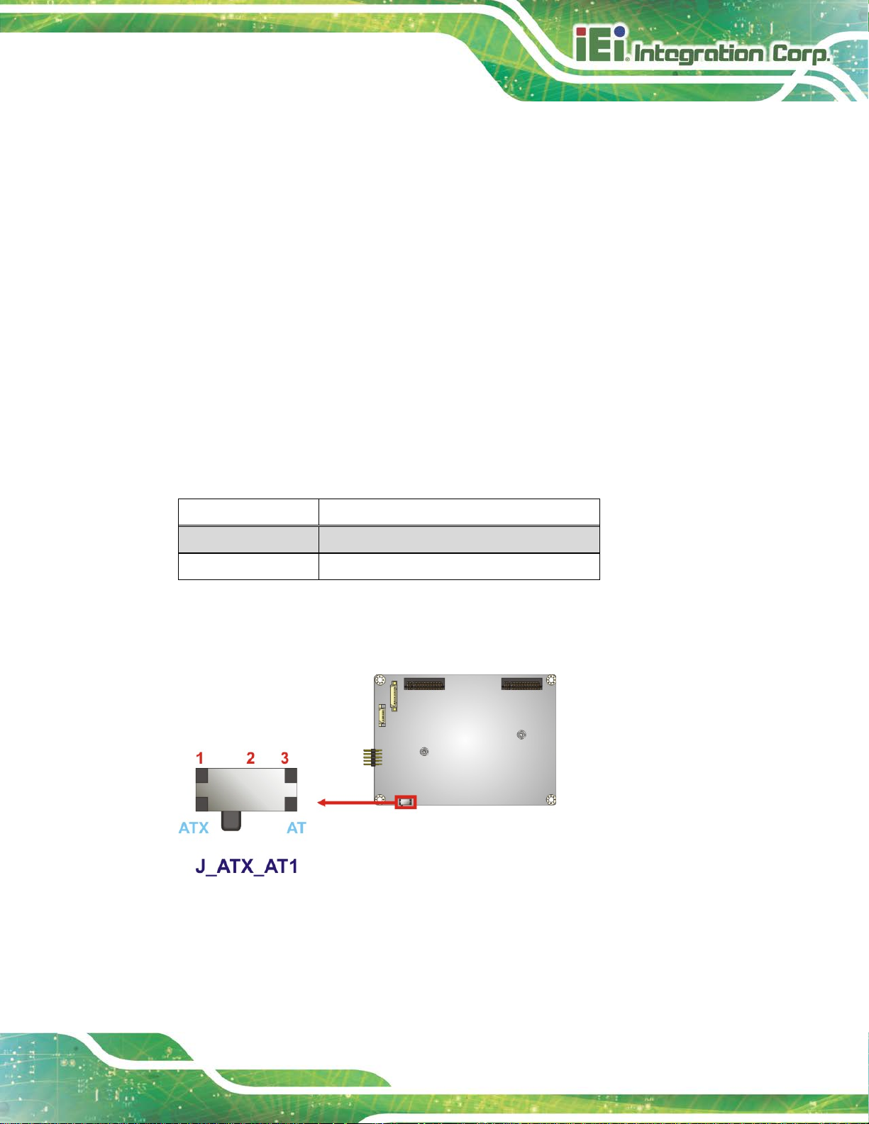
4.5.1 AT/ATX Mode Select Switch
CN Label:
CN Type:
CN Location:
CN Settings:
The AT/ATX mode select switch specifies the systems power mode as AT or ATX.
AT/ATX mode select switch settings are shown in Table 4-1.
Setting Description
Short 1-2 ATX Mode (Default)
Short 2-3 AT Mode
Table 4-1: AT/ATX Mode Select Switch Settings
The location of the AT/ATX mode select switch is shown in Figure 4-4 below.
J_ATX_AT1
Switch
See Figure 4-4
See Table 4-1
Figure 4-4: A T/A TX Mode Select Switch Location
Page 54

HYPER-AL SBC
Page 42
4.5.1 LVDS Voltage Selection
WARNING:
Incorrect voltages can destroy the LCD panel. Make sure to select a
voltage that matches the voltage required by the LCD panel.
Jumper Label: J_VLVDS1
Jumper Type:
Jumper Settings:
Jumper Location:
The LCD voltage selection jumper sets the voltage of the power supplied of the LCD
panel.
Setting Description
Short 1-3 Backlight Enable +3.3 V
Short 2-4 Set the voltage level of pane l to +3.3 V
Short 3-5 Backlight Enable +5 V
Short 4-6 Set the voltage level of panel to +5 V
Table 4-2: LVDS Voltage Selection Jumper Settings
6-pin header, p=2.00 mm
See Table 4-2
See Figure 4-5
Figure 4-5: LVDS Voltage Selection Jumper Location
Page 55

HYPER-AL SBC
Page 43
components within recommended
operating temperatures. The chassis should have fans and vents as
secured to the
4.6 Chassis Installation
4.6.1 Airflow
WARNING:
Airflow is critical for keeping
necessary to keep things cool.
The HYPER-AL must be installed in a chassis with ventilation holes on the sides allowing
airflow to travel through the heat sink surface. In a system with an individual power supply
unit, the cooling fan of a power supply can also help generate airflow through the board
surface.
4.6.2 Heat Spreader Installation
WARNING:
Never run the HYPER-AL without the heat spreader
board. The heat spreader ensures the system remains cool and does
not need addition heat sinks to cool the system.
A heat spreader is shipped with the HYPER-AL. The heat spreader must be installed on to
the HYPER-AL before operation.
4.6.3 Motherboard Installation
To install the HYPER-AL motherboard into the chassis please refer to the reference
material that came with the chassis.
Page 56

HYPER-AL SBC
Page 44
4.7 Internal Peripheral Device Connections
This section outlines the installation of peri pheral devices to the onboard connectors.
4.7.1 SATA Drive Connection
The HYPER-AL is shipped with one SATA cable. To connect the SATA drive to the
connector, please follow the steps below.
Step 1: Locate the SA TA connector and the SATA power connector. The locations of
the connectors are shown in Chapter 3.
Step 2: Insert the cable connector. Insert the cable connector into the on-board SATA
drive connector and the SATA power connector. See Figure 4-6.
NOTE:
The connector locations in the following diagram are just for reference.
For the exact locations, please see Section 3.2.3 and Section 3.2.4.
Page 57

HYPER-AL SBC
Page 45
Figure 4-6: SATA Drive Cable Connection
Step 3: Connect the cable to the SATA disk. Connect the connector on the other end
of the cable to the connector at the back of t he SATA drive. See Figure 4-6.
Step 4: To remove the SATA cable from the SATA connector, press the clip on the
connector at the end of the cable. Step 0:
Page 58

HYPER-AL SBC
Page 46
Chapter
5
5 BIOS
Page 59

HYPER-AL SBC
Page 47
Some of the BIOS options may vary throughout the life cycle of the
5.1 Introduction
The BIOS is programmed onto the BIOS chip. The BI OS setup pro gram allows changes to
certain system settings. This chapter outli nes t he options that can be changed.
NOTE:
product and are subject to change without prior notice .
5.1.1 Starting Setup
The UEFI BIOS is activated when the computer is turned on. The setup program can be
activated in one of two ways.
1. Press the D
2. Press the D
appears on the screen. 0.
If the message disappears before the D
and try again.
ELETE or F2 key as soon as the system is turned on or
ELETE or F2 key when the “Press Del to enter SETUP” message
ELETE or F2 key is pressed, restart the computer
5.1.2 Using Setup
Use the arrow keys to highlight items, press ENTER to select, use the PageUp and
PageDown keys to change entries, press F1 for help and press E
keys are shown in Table 5-1.
Key Function
Up arrow Move to previous item
Down arrow Move to next item
Left arrow Move to the item on the left hand side
SC to quit. Navigation
Right arrow Move to the item on the right hand side
+ Increase the numeric value or make changes
Page 60

HYPER-AL SBC
Page 48
Key Function
- Decrease the numeric value or make change s
F1 key General help, only for Status Page Setup Menu and Option
Page Setup Menu
F2 key Load previous values.
F3 key Load optimized def aul ts
F4 key Save changes and Ex i t BIOS
Esc key Main Menu – Quit and not save changes into CMOS
Status Page Setup Menu and Option Page Setup Menu --
Exit current page and return to Main Menu
Table 5-1: BIOS Navigation Keys
5.1.3 Getting Help
When F1 is pressed a small help window describing the appropriate keys to use and the
possible selections for the highlighted item appears. To ex it the Help Window press E
the F1 key again.
5.1.4 Unable to Reboot after Configuration Changes
If the computer cannot boot after changes to the system configuration is made, clear
CMOS defaults by disconnecting the battery from the battery connector described in
Section 3.2.2.
5.1.5 BIOS Menu Bar
The menu bar on top of the BIOS screen has the foll owing main items:
Main – Changes the basic system configuration.
Advanced – Changes the advanced system settings.
Chipset – Changes the chipset settings.
SC or
Security – Sets User and Supervisor Passwords.
Boot – Changes the system boot configuration.
Save & Exit – Selects exit options and loads default settings
Page 61

HYPER-AL SBC
Page 49
Aptio Setup Utility – Copyright (C) 2018 American Megatrends, Inc.
Main
Advanced
Chipset
Security
Boot
Save & Exit
Version 2.18.1263. Copyright (C) 2018 American Megatrends, Inc.
The following sections completely describe the configuration options found in the menu
items at the top of the BIOS screen and listed above.
5.2 Main
The Main BIOS menu (BIOS Menu 1) appears when the BIOS Setup program is entered.
The Main menu gives an overview of the basic syste m i nformation.
BIOS Information
BIOS Vendor American Megatrends
Core Version 5.12
Compliency UEFI 2.5; PI 1.4
Project Version B495AR11.BIN
Build Date and Time 06/04/2018 21:16:43
iWDD Vendor iEi
iWDD Version B4950510.bin
Platform firmware Information
BXT SOC B1
MRC Version 0.56
PUNIT FW 2E
PMC FW 03.29
TXE FW 3.1.50.2222
ISH FW 4.1.0.3364
GOP 0.0.0036
Memory Information
Total Memory 2048 MB
Memory Speed 1600 MHz
Access Level Administrator
System Date [Fri 01/01/2010]
System Time [00:10:30]
Set the Date. Use Tab to
switch between Data
elements.
---------------------
: Select Screen
↑ ↓: Select Item
Enter Select
+/-: Change Opt.
F1: General Help
F2: Previous Values
F3: Optimized Defaults
F4: Save & Exit
ESC: Exit
BIOS Menu 1: Main
System Date [xx/xx/xx]
Use the System Date option to set the system date. Manually enter the day, month and
year.
Page 62

HYPER-AL SBC
Page 50
Aptio Setup Utility – Copyright (C) 2018 American Megatrends, Inc.
Main
Advanced
Chipset
Security
Boot
Save & Exit
Version 2.18.1263. Copyright (C) 2018 American Megatrends, Inc.
System Time [xx:xx:xx]
Use the System Time option to set the system time. Manually enter the hours, minutes
and seconds.
5.3 Advanced
Use the Advanced menu (BIOS Menu 2) to configure the CPU and peripheral devices
through the following sub-menus:
WARNING!
Setting the wrong values in the sections below may cause the system
to malfunction. Make sure that the settings made are compatible with
the hardware.
> ACPI Settings
> iWDD H/W Monitor
> iWDD Super IO Configuration
> USB Configuration
> CPU Configuration
> RTC Wake Settings
> Power Saving Configuration
> Serial Port Console Redirection
> iEi Feature
BIOS Menu 2: Advanced
System ACPI Parameters.
----------------------
: Select Screen
↑ ↓: Select Item
Enter Select
F1 General Help
F2 Previous Values
F3 Optimized Defaults
F4 Save
ESC Exit
Page 63

HYPER-AL SBC
Page 51
Aptio Setup Utility – Copyright (C) 2018 American Megatrends, Inc.
Advanced
ESC: Exit
Version 2.18.1263. Copyright (C) 2018 American Megatrends, Inc.
S3 (Suspend to
off. Power to the RAM is maintained. The
computer returns slower to a working state, but
5.3.1 ACPI Settings
The ACPI Settings menu (BIOS Menu 3) configures the Advanced Configuration and
Power Interface (ACPI) options.
ACPI Settings
ACPI Sleep State [S3 (Suspend to RAM]
BIOS Menu 3: ACPI Settings
ACPI Sleep State [S3 (Suspend to RAM)]
Use the ACPI Sleep State option to specify the sleep state the system enters when it is
not being used.
----------------------
: Select Screen
↑ ↓: Select Item
Enter Select
+/-: Change Opt.
F1: General Help
F2: Previous Values
F3: Optimized Defaults
F4: Save & Exit
RAM)
DEFAULT
The caches are flushed and the CPU is powered
more power is saved.
Page 64

HYPER-AL SBC
Page 52
Aptio Setup Utility – Copyright (C) 2018 American Megatrends, Inc.
Advanced
ESC Exit
Version 2.18.1263. Copyright (C) 2018 American Megatrends, Inc.
5.3.2 iWDD H/W Monitor
The iWDD H/W Monitor menu (BIOS Menu 4) contains the fan configuration submenus
and displays operating temperature, fan speeds and system voltages.
PC Health Status
CPU temperature :+30 °C
CPU_CORE :+0.765 V
+12V :+12.032 V
+DDR :+1.278 V
+5VSB :+5.014 V
+3.3V :+3.288 V
+3.3VSB :+3.313 V
BIOS Menu 4: iWDD H/W Monitor
PC Health Status
The following system parameters and values are shown. The system parameters that are
monitored are:
---------------------
: Select Screen
↑ ↓: Select Item
Enter Select
+ - Change Opt.
F1 General Help
F2 Previous Values
F3 Optimized Defaults
F4 Save & Exit
System Temperatures
Voltages
o CPU_CORE
o +12V
o +DDR
o +5VSB
o +3.3V
o +3.3VSB
Page 65

HYPER-AL SBC
Page 53
Aptio Setup Utility – Copyright (C) 2018 American Megatrends, Inc.
Advanced
Version 2.18.1263. Copyright (C) 2018 American Megatrends, Inc.
Aptio Setup Utility – Copyright (C) 2018 American Megatrends, Inc.
Advanced
ESC Exit
Version 2.18.1263. Copyright (C) 2018 American Megatrends, Inc.
5.3.3 iWDD Super IO Configuration
Use the iWDD Super IO Configuration menu (BIOS Menu 5) to set or change the
configurations for the serial ports.
iWDD Super IO Configuration
Super IO Chip iWDD
> Serial Port 1 Configuration
BIOS Menu 5: iWDD Super IO Configuration
5.3.3.1 Serial Port 1 Configuration
Use the Serial Port 1 Configuration menu (BIOS Menu 6) to configure the serial port 1.
Set Parameters of Serial
Port 1 (COMA)
---------------------
: Select Screen
↑ ↓: Select Item
Enter Select
F1 General Help
F2 Previous Values
F3 Optimized
Defaults
F4 Save
ESC Exit
Serial Port 1 Configuration
Serial Port [Enabled]
Device Settings IO=3F8h; IRQ=4
Change Settings [Auto]
BIOS Menu 6: Serial Port 1 Configuration
Enable or Disable Serial
Port (COM)
---------------------
: Select Screen
↑ ↓: Select Item
Enter Select
F1 General Help
F2 Previous Values
F3 Optimized
Defaults
F4 Save
Page 66

HYPER-AL SBC
Page 54
Serial Port [Enabled]
Use the Serial Port option to enable or disable the serial port.
Disabled
Enabled DEFAULT
Change Settings [IO=3F8h; IRQ=4]
Use the Change Settings option to change the serial port IO port address and interrupt
address.
Auto DEFAULT
IO=3F8h; IRQ=4
IO=3F8h;
IRQ=4, 10, 11
IO=2F8h;
IRQ=4, 10, 11
Disable the serial port
Enable the serial port
The serial port IO port address and interrupt
address are automatically detected.
Serial Port I/O port address is 3F8h and the
interrupt address is IRQ4
Serial Port I/O port address is 3F8h and the
interrupt address is IRQ4, 10, 11
Serial Port I/O port address is 2F8h and the
interrupt address is IRQ4, 10, 11
IO=3E8h;
IRQ=4, 10, 11
IO=2E8h;
IRQ=4, 10, 11
Serial Port I/O port address is 3E8h and the
interrupt address is IRQ4, 10, 11
Serial Port I/O port address is 2E8h and the
interrupt address is IRQ4, 10, 11
Page 67

HYPER-AL SBC
Page 55
Aptio Setup Utility – Copyright (C) 2018 American Megatrends, Inc.
Advanced
disables legacy support
ESC Exit
Version 2.18.1263. Copyright (C) 2018 American Megatrends, Inc.
5.3.4 USB Configuration
Use the USB Configuration menu (BIOS Menu 7) to read USB configuration information
and configure the USB settings.
USB Configuration
USB Devices:
1 Keyboard
Legacy USB Support [Enabled]
BIOS Menu 7: USB Configuration
USB Devices
Enables Legacy USB
support. AUTO option
if no USB devices are
connected. DISABLE
option will keep USB
devices available only
for EFI applications.
---------------------
: Select Screen
↑ ↓: Select Item
Enter Select
F1 General Help
F2 Previous Values
F3 Optimized
Defaults
F4 Save
The USB Devices Enabled field lists th e US B devices that are enabled on the system
Legacy USB Support [Enabled]
Use the Legacy USB Support BIOS option to enable USB mouse and USB keyboard
support. Normally if this option is not enable d, any a t tached USB m ouse o r USB keyboa rd
does not become available until a USB comp atible operat ing syst em is fully bo oted with all
USB drivers loaded. When this option is enabled, any attached USB mouse or USB
keyboard can control the system even when there is no USB driver loaded onto the
system.
Enabled DEFAULT
Legacy USB support enabled
Page 68

HYPER-AL SBC
Page 56
Aptio Setup Utility – Copyright (C) 2018 American Megatrends, Inc.
Advanced
Version 2.18.1263. Copyright (C) 2018 American Megatrends, Inc.
Disabled
Auto
Legacy USB support disabled
Legacy USB support disabled if no USB devices are
connected
5.3.5 CPU Configuration
Use the CPU Configuration menu (BIOS Menu 8) to view detailed CPU specifications
and configure the CPU.
CPU Configuration
Intel(R) Celeron(R) CPU N3350 @ 1.10GHz
CPU Signature 506C9
Microcode Patch 2E
Max CPU Speed 1100 MHz
Min CPU Speed 800 MHz
Processor Cores 2
Intel HT Technology Not Supported
Intel VT-x Technology Supported
L1 Data Cache 24 KB x 2
L1 Code Cache 32 KB x 2
L2 Cache 1024 KB x 2
L3 Cache Not Present
EIST [Enabled]
C-States [Disabled]
Intel Virtualization Technology [Disabled]
VT-d [Disabled]
Enable/Disable Intel
SpeedStep
----------------------
: Select Screen
↑ ↓: Select Item
Enter Select
F1 General Help
F2 Previous Values
F3 Optimized
Defaults
F4 Save
ESC Exit
BIOS Menu 8: CPU Configuration
EIST [Enabled]
Use the EIST option to enable or disable the Intel
Disabled
Enabled DEFAULT
Disables the Intel
Enables the Intel
®
Speed Step Technology.
®
Speed Step Technology.
®
Speed Step Technology.
Page 69

HYPER-AL SBC
Page 57
C-States [Disabled]
Use the C-States option to enable or disable the C-states.
Disabled DEFAULT
Enabled
Intel Virtualization Technology [Disabled]
Use the Intel Virtualization Technology option to enable or disable virtualization on the
system. When combined with third party software, Intel
several OSs to run on the same system at the same time.
Disabled DEFAULT
Enabled
VT-d [Disabled]
Use the VT-d BIOS option to enable or disabled VT-d support.
Disabled DEFAULT
Disables the C-state
Enables the C-state
Disables Intel
Enables Intel
Disable VT-d support.
®
®
Virtualization Technology.
®
Virtualization technology allows
Virtualization Technology.
Enabled
Enable VT-d support.
Page 70

HYPER-AL SBC
Page 58
Aptio Setup Utility – Copyright (C) 2018 American Megatrends, Inc.
Advanced
ESC Exit
Version 2.18.1263. Copyright (C) 2018 American Megatrends, Inc.
real time clock (RTC) cannot generate a wake
every day at the specified time. Besides, the
n be
5.3.6 RTC Wake Settings
The RTC Wake Settings menu (BIOS Menu 9) conf igure s RTC wake event .
Wake system with Fixed Time [Disabled]
BIOS Menu 9: RTC Wake Settings
Wake system with Fixed Time [Disabled]
Use the Wake system with Fixed Time option to enable or disable the system wake on
Enable or disable System
wake on alarm event. When
enabled, System will
wake on the
date::hr::min::sec
specified
----------------------
: Select Screen
↑ ↓: Select Item
Enter Select
F1 General Help
F2 Previous Values
F3 Optimized Defaults
F4 Save
alarm event.
Disabled D
Enabled
EFAULT
The
event
If selected, the Wake up every day option appears
allowing you to enable to disable the sy st em t o wake
following options appear with values that ca
selected:
Wake up date
Wake up hour
Wake up minute
Page 71

HYPER-AL SBC
Page 59
Aptio Setup Utility – Copyright (C) 2018 American Megatrends, Inc.
Advanced
ESC Exit
Version 2.18.1263. Copyright (C) 2018 American Megatrends, Inc.
5.3.7 Power Saving Configuration
Use the Power Saving Configuration menu (BIOS Menu 10) to configure system to
reduce power consumption in system off state.
Wake up second
After setting the alarm, the computer turns itself on
from a suspend state when the alarm goes off.
Power Saving Configuration
Power Saving Function [Disabled]
BIOS Menu 10: Power Saving Configuration
Power Saving Function(ERP) [Disabled]
Use the Power Saving Function BIOS option to enable or disable the power saving
function.
Enable or Disable to
reduce power consumption
in system off state.
---------------------
: Select Screen
↑ ↓: Select Item
Enter Select
F1 General Help
F2 Previous Values
F3 Optimized
Defaults
F4 Save
Disabled DEFAULT
Enabled
Power saving function is disabled.
Power saving function is enabled. It will reduce power
consumption when the system is of f.
Page 72

HYPER-AL SBC
Page 60
Aptio Setup Utility – Copyright (C) 2018 American Megatrends, Inc.
Advanced
ESC Exit
Version 2.18.1263. Copyright (C) 2018 American Megatrends, Inc.
5.3.8 Serial Port Console Redirection
The Serial Port Console Redirection menu (BIOS Menu 11) allows the console
redirection options to be configured. Console redirection allows users to maintain a
system remotely by re-directing keyboard input and text output through the serial port .
COM1
Console Redirection [Disabled]
> Console Redirection Settings
Legacy Console Redirection
> Legacy Console Redirection Settings
BIOS Menu 11: Serial Port Console Redirection
Console Redirection [Disabled]
Use Console Redirection option to enable or disable the con sole redirection function.
Disabled DEFAULT
Disabled the console redirection function
Console Redirection
Enable or Disable
---------------------
: Select Screen
↑ ↓: Select Item
Enter Select
F1 General Help
F2 Previous Values
F3 Optimized
Defaults
F4 Save
Enabled
Enabled the console redirection function
Page 73

HYPER-AL SBC
Page 61
Aptio Setup Utility – Copyright (C) 2018 American Megatrends, Inc.
Advanced
Version 2.18.1263. Copyright (C) 2018 American Megatrends, Inc.
5.3.8.1 Legacy Console Redirection Settings
The Legacy Console Redirection Settings menu (BIOS Menu 12) allows the legacy
console redirection options to be configured.
Legacy Serial Redirection Port [COM1]
BIOS Menu 12: Legacy Console Redirection Settings
Legacy Serial Redirection Port [COM1]
Use the Legacy Serial Redirection Port option to specify a COM port to display
redirection of legacy OS and legacy OPROM mes sages. The options include:
Select a COM port to
display redirection of
Legacy OS and Legacy
OPROM Messages
---------------------
: Select Screen
↑ ↓: Select Item
Enter Select
F1 General Help
F2 Previous Values
F3 Optimized
Defaults
F4 Save
ESC Exit
COM1 D
EFAULT
Page 74

HYPER-AL SBC
Page 62
Aptio Setup Utility – Copyright (C) 2018 American Megatrends, Inc.
Advanced
crashes. Please install
service before enabling
ESC Exit
Version 2.18.1263. Copyright (C) 2018 American Megatrends, Inc.
5.3.9 IEI Feature
Use the IEI Feature menu (BIOS Menu 13) to configure One Key Recovery function.
iEi Feature
Auto Recovery Function [Disabled]
BIOS Menu 13: IEI Feature
Auto Recovery Function [Disabled]
Auto Recovery Function
Reboot and recover
system automatically
within 10 min, when OS
Auto Recovery API
this function
----------------------
: Select Screen
↑ ↓: Select Item
Enter Select
F1 General Help
F2 Previous Values
F3 Optimized Defaults
F4 Save
Use the Auto Recovery Function BIOS option to enable or disable the auto r ecovery
function of the IEI One Key Recovery.
Disabled DEFAULT
Enabled
Auto recovery function disabled
Auto recovery function enabled
Page 75

HYPER-AL SBC
Page 63
Aptio Setup Utility – Copyright (C) 2018 American Megatrends, Inc.
Main
Advanced
Chipset
Security
Boot
Save & Exit
ESC Exit
Version 2.18.1263. Copyright (C) 2018 American Megatrends, Inc.
5.4 Chipset
Use the Chipset menu (BIOS Menu 14) to access the north bridge and south bridge
configuration menus
WARNING!
Setting the wrong values for the Chipset B IOS selections in the Chipset
BIOS menu may cause the system to malfunction.
> North Bridge
> South Bridge
BIOS Menu 14: Chipset
North Bridge Parameters
---------------------
: Select Screen
↑ ↓: Select Item
Enter Select
+/-: Change Opt.
F1 General Help
F2 Previous Values
F3 Optimized Defaults
F4 Save & Exit
Page 76

HYPER-AL SBC
Page 64
Aptio Setup Utility – Copyright (C) 2018 American Megatrends, Inc.
Chipset
Version 2.17.1249. Copyright (C) 2018 American Megatrends, Inc.
5.4.1 North Bridge Configuration
Use the North Bridge Configuration menu (BIOS Menu 15) to configure the Intel IGD
settings.
> Intel IGD Configuration
> LCD Control
Memory Information
Total Memory 2048 MB(LPDDR3)
DIMM1 2048 MB(LPDDR3)
BIOS Menu 15: North Bridge Configuration
Memory Information
The Memory Information lists a brief summary of the on-board memory. The fields in
Memory Information cannot be changed.
Intel IGD Configuration
---------------------
: Select Screen
↑ ↓: Select Item
Enter Select
+/-: Change Opt.
F1: General Help
F2: Previous Values
F3: Optimized Defaults
F4: Save & Exit
ESC: Exit
5.4.1.1 Intel IGD Configuration
Use the Intel IGD Configuration menu (BIOS Menu 16) to configure the video device
connected to the system.
Page 77

HYPER-AL SBC
Page 65
Aptio Setup Utility – Copyright (C) 2018 American Megatrends, Inc.
Chipset
Select which of IGD/PCI
ESC: Exit
Version 2.18.1263. Copyright (C) 2018 American Megatrends, Inc.
Enabled Integrated Graphics Device (IGD) when
IGD Configuration
Primary Display [IGD]
Integrated Graphics Device [Enable]
DVMT Pre-Allocated [256M]
DVMT Total Gfx Mem [MAX]
BIOS Menu 16: Intel IGD Configuration
Primary Display [IGD]
Graphics device should
be Primary Display.
---------------------
: Select Screen
↑ ↓: Select Item
Enter Select
+/-: Change Opt.
F1: General Help
F2: Previous Values
F3: Optimized Defaults
F4: Save & Exit
Use the Primary Display option to select the graphics controller used as the primary boot
device. Configuration option includes:
Integrated Graphics Device [Enable]
Use the Integrated Graphics Device option to enable or disable Integrated Graphics
Device (IGD).
DVMT Pre-Allocated [256MB]
Use the DVMT Pre-Allocated option to set the amount of system memory allo cated to the
integrated graphics processor when the system boots. The system memory allocated can
IGD
Disable
Enable DEFAULT
DEFAULT
Always disable IGD.
selected as the Primary Video Adaptor.
then only be used as graphics memory, and is no longer available to applications or the
operating system. Configuration option s are listed below:
Page 78

HYPER-AL SBC
Page 66
Aptio Setup Utility – Copyright (C) 2018 American Megatrends, Inc.
Chipset
ESC: Exit
Version 2.18.1263. Copyright (C) 2018 American Megatrends, Inc.
64M
128M
256M D
512M
DVMT Total Gfx Mem [MAX]
Use the DVMT Total Gfx Mem option to select DVMT5.0 total graphic memory size used
by the internal graphic device. The following options are available:
128M
256M
MAX D
EFAULT
EFAULT
5.4.1.2 LCD Control
Use the LCD Control submenu (BIOS Menu 17) to select a display device which will be
activated during POST.
LCD Control
Primary IGFX Boot Display [Auto]
LVDS Panel Detect [INSTALLED]
On board LVDS [Disabled]
Panel Setting
Backlight Control Mode [LED]
Backlight Control Type [PWM]
Backlight Control Voltage Level [3.3V]
LCD Panel Type [800x600 18bit]
BIOS Menu 17: LCD Control
Select the Video Device which
will be activated during POST.
This has no effect if external
graphics present. Secondary
boot display selection will
appear based on your
selection. VGA modes will be
supported only on primary
display.
---------------------
: Select Screen
↑ ↓: Select Item
Enter Select
+/-: Change Opt.
F1: General Help
F2: Previous Values
F3: Optimized Defaults
F4: Save & Exit
Page 79

HYPER-AL SBC
Page 67
Primary IGFX Boot Display [Auto]
Use the Primary IGFX Boot Display option to select the display device used by the
system when it boots. Configuration options are listed below.
Auto D
HDMI1
LVDS
On board LVDS [Disabled]
Use the On board LVDS option to enable or disable the LV DS connector.
Disabled DEFAULT
Enabled
Backlight Control Mode [LED]
Use the Backlight Control Mode option to specify the backlight control mode.
Configuration options are listed below.
LED D
CCFL
EFAULT
Disable LVDS.
Enabled LVDS.
EFAULT
Backlight Control Type [PWM]
Use the Backlight Control Type option to specify the backlight control type.
Configuration options are listed below.
PWM D
DC
Backlight Control Voltage Level [3.3V]
Use the Backlight Control Voltage Level option to specify the voltage of the power
supplied to the LCD panel. Configuration options are listed below.
3.3V D
5.0V
EFAULT
EFAULT
Page 80

HYPER-AL SBC
Page 68
Aptio Setup Utility – Copyright (C) 2018 American Megatrends, Inc.
Chipset
ESC: Exit
Version 2.18.1263. Copyright (C) 2018 American Megatrends, Inc.
LCD Panel Type [800x600 18bit]
Use the LCD Panel Type option to select the type of flat panel connected to the system.
Configuration options are listed below.
800x600 18bit
1024x768 18bit
1024x768 24bit
1280x768 18bit
1280x800 18bit
1280x960 18bit
1366x768 18bit
1366x768 24bit
DEFAULT
5.4.2 South Bridge Configuration
Use the South Bridge Configuration menu (BIOS Menu 18) to configure the south
bridge chipset.
Auto Power Button Function [Disable (ATX)]
> HD-Audio Configuration
> PCI Express Configuration
> SATA Configuration
Restore AC Power Loss [Last State]
HD-Audio Configuration
Settings.
---------------------
: Select Screen
↑ ↓: Select Item
Enter Select
+/-: Change Opt.
F1: General Help
F2: Previous Values
F3: Optimized Defaults
F4: Save & Exit
BIOS Menu 18: South Bridge Configuration
Restore on AC Power Loss [Last State ]
Use the Restore on AC Power Loss BIOS option to specify what state the system
returns to if there is a sudden loss of power to the system.
Page 81

HYPER-AL SBC
Page 69
Aptio Setup Utility – Copyright (C) 2018 American Megatrends, Inc.
Chipset
Audio
Version 2.18.1263. Copyright (C) 2018 American Megatrends, Inc.
Power Off
Power On
Last State DEFAULT
The system remains turned of f
The system turns on
The system returns to its previous state. If it was on, it
turns itself on. If it was off, it remains off.
5.4.2.1 HD-Audio Configuration
Use the HD-Audio Configuration menu (BIOS Menu 19) to configure the HD Audio.
HD-Audio Configuration
HD-Audio Support [Enable]
Enable/Disable HDSupport
---------------------
: Select Screen
↑ ↓: Select Item
Enter Select
F1 General Help
F2 Previous Values
F3 Optimized
Defaults
F4 Save
ESC Exit
BIOS Menu 19: HD-Audio Configuration
HD-Audio Support [Enable]
Use the HD-Audio Support option to enable or disable the High Definition Audio
controller.
Disable
Enable DEFAULT
The onboard HDA controller is disabled
The onboard HDA is detected automatically and enabled
Page 82

HYPER-AL SBC
Page 70
Aptio Setup Utility – Copyright (C) 2018 American Megatrends, Inc.
Chipset
Version 2.18.1263. Copyright (C) 2018 American Megatrends, Inc.
5.4.2.2 PCI Express Configuration
Use the PCI Express Configuration menu (BIOS Menu 20) to configure the PCI
Express.
PCI Express Configuration
> M2_CN1
BIOS Menu 20: PCI Express Configuration
Compliance Mode
Enable/Disable
---------------------
: Select Screen
↑ ↓: Select Item
Enter Select
F1 General Help
F2 Previous Values
F3 Optimized
Defaults
F4 Save
ESC Exit
Page 83

HYPER-AL SBC
Page 71
Aptio Setup Utility – Copyright (C) 2018 American Megatrends, Inc.
Chipset
Express Root
Auto: To disable unused root
Version 2.18.1263. Copyright (C) 2018 American Megatrends, Inc.
unused port automatically for the
5.4.2.2.1 M2_CN1
Use the M2_CN1 menus (BIOS Menu 21) to configure the M.2 A-key slot.
M2_CN1 [Enable]
PCIe Speed [Auto]
BIOS Menu 21: M2_CN1
M2_CN1 [Enable]
Control the PCI
Port.
port automatically for the
most optimum power savings.
Enable: Enable PCIe root port
Disable: Disable PCIe root
port
---------------------
: Select Screen
↑ ↓: Select Item
Enter Select
F1 General Help
F2 Previous Values
F3 Optimized Defaults
F4 Save
ESC Exit
Use the M2_CN1 option to enable or disable the M.2 A-key slot.
PCIe Speed [Auto]
Use the PCIe Speed option to configure the M.2 A-key slot speed.
Disabled
Enabled DEFAULT
Auto
Auto DEFAULT
Gen 1
Disables the M.2 A-key slot.
Enables the M.2 A-key slot.
Disables the
most optimum power savings.
Configure M.2 A-key speed to auto
Configure M.2 A-key slot speed to Gen1
Page 84

HYPER-AL SBC
Page 72
Aptio Setup Utility – Copyright (C) 2018 American Megatrends, Inc.
Chipset
Enables or Disables the
controller supports the
ESC Exit
Version 2.18.1263. Copyright (C) 2018 American Megatrends, Inc.
Gen 2
Configure M.2 A-key slot speed to Gen2
5.4.2.3 SATA Configuration
Use the SATA Configuration menu (BIOS Menu 22) to change and/or set the
configuration of the SATA devices installed in the system.
SATA Configuration
STAT Controller [Enable]
SATA Mode Selection [AHCI]
SATA1 Empty
Hot Plug [Disabled]
M2_1 Empty
Chipset SATA Controller.
The Chipset SATA
2 black internal SATA
ports (up to 3Gb/s
supported per port).
---------------------
: Select Screen
↑ ↓: Select Item
Enter Select
F1 General Help
F2 Previous Values
F3 Optimized
Defaults
F4 Save
STAT Controller [Enable]
Use the STAT Controller(s) option to enable or disable t he SATA device.
SATA Mode Selection [AHCI]
Use the SATA Mode Selection option to configure SATA devices as AHCI devices.
BIOS Menu 22: SATA Configuration
Enable DEFAULT
Disable
AHCI DEFAULT
Enables the SATA device.
Disables the SATA device.
Configures SATA devices as AHCI device.
Page 85

HYPER-AL SBC
Page 73
Aptio Setup Utility – Copyright (C) 2018 American Megatrends, Inc.
Main
Advanced
Chipset
Security
Boot
Save & Exit
Version 2.18.1263. Copyright (C) 2018 American Megatrends, Inc.
Hot Plug [Disabled]
Use the Hot Plug option to enable or disable the SATA device hot plug.
Disabled DEFAULT
Enabled
Disables the SATA device hot plug.
Enables the SATA device hot plug
5.5 Security
Use the Security menu (BIOS Menu 23) to set system and user passwords.
Password Description
If ONLY the Administrator’s password is set,
then this only limits access to Setup and is
only asked for when entering Setup
If ONLY the User’s password is set, then this
is a power on password and must be entered to
boot or enter Setup. In Setup the User will
have Administrator rights.
The password length must be:
Minimum length 3
Maximum length 20
Administrator Password
User Password
Set Administrator
Password
---------------------
: Select Screen
↑ ↓: Select Item
Enter Select
F1 General Help
F2 Previous Values
F3 Optimized
Defaults
F4 Save
ESC Exit
BIOS Menu 23: Security
Administrator Password
Use the Administrator Password to set or change a administrator password.
User Password
Use the User Password to set or change a user pass word.
Page 86

HYPER-AL SBC
Page 74
Aptio Setup Utility – Copyright (C) 2018 American Megatrends, Inc.
Main
Advanced
Chipset
Security
Boot
Save & Exit
Version 2.18.1263. Copyright (C) 2018 American Megatrends, Inc.
Allows the Number Lock on the keyboard to be
enabled automatically when the computer system
boots up. This allows the immediate use of the
the keyboard. To confirm this, the Number Lock LED
Does not enable the keyboard Number Lock
press the Number Lock key located on the upper
key pad. The Number
5.6 Boot
Use the Boot menu (BIOS Menu 24) to configure system boot options.
Boot Configuration
Bootup NumLock State [On]
Quiet Boot [Enabled]
Launch PXE OpROM [Disabled]
Option ROM Messages [Force BIOS]
UEFI Boot [Disabled]
Boot Option Priorities
BIOS Menu 24: Boot
Bootup NumLock State [On]
Use the Bootup NumLock State BIOS option to specify if the number lock setting must
be modified during boot up.
On DEFAULT
Select the keyboard
NumLock state
---------------------
: Select Screen
↑ ↓: Select Item
Enter Select
F1 General Help
F2 Previous Values
F3 Optimized Defaults
F4 Save
ESC Exit
Off
10-key numeric keypad located on the right side of
light on the keyboard is lit.
automatically. To use the 10-keys on the keyboard,
left-hand corner of the 10Lock LED on the keyboard lights up when the
Number Lock is engaged.
Page 87

HYPER-AL SBC
Page 75
Quiet Boot [Enabled]
Use the Quiet Boot BIOS option to select the scre en display when the system boots.
Disabled
Enabled DEFAULT
Launch PXE OpROM [Disabled]
Use the Launch PXE OpROM option to enable or disable boot option for legacy network
devices.
Disabled DEFAULT
Enabled
Option ROM Messages [Force BIOS]
Use the Option ROM Messages option to set the Option ROM display mode.
Force
BIOS
DEFAULT
Normal POST messages displayed
OEM Logo displayed instead of POST m essages
Ignore all PXE Option ROMs
Load PXE Option ROMs.
Sets display mode to force BIOS.
Keep
Current
UEFI Boot [Disabled]
Use the UEFI Boot option to enable or disable to boot f rom the UEFI devices.
Enabled
Disabled DEFAULT
Boot Option Priority
Use the Boot Option Priority function to set the system boot se quence from t he available
devices. The drive sequence also depends on the boot sequence in the individual device
section.
Sets display mode to current.
Boot from UEFI devices is enabled.
Boot from UEFI devices is disabled.
Page 88

HYPER-AL SBC
Page 76
Aptio Setup Utility – Copyright (C) 2018 American Megatrends, Inc.
Main
Advanced
Chipset
Security
Boot
Save & Exit
ESC Exit
Version 2.18.1263. Copyright (C) 2018 American Megatrends, Inc.
5.7 Save & Exit
Use the Save & Exit menu (BIOS Menu 25) to load default BIOS values, optimal failsafe
values and to save configuration changes.
Save Changes and Reset
Discard Changes and Reset
Restore Defaults
Save as User Defaults
Restore User Defaults
BIOS Menu 25: Save & Exit
Save Changes and Reset
Use the Save Changes and Reset option to save the changes made to the BIOS options
Reset the system after
saving the changes.
---------------------
: Select Screen
↑ ↓: Select Item
Enter Select
F1 General Help
F2 Previous Values
F3 Optimized
Defaults
F4 Save
and to exit the BIOS configuration setup program.
Discard Changes and Reset
Use the Discard Changes and Reset option to exit the system without saving the
changes made to the BIOS configuration setup program.
Restore Defaults
Use the Restore Defaults option to load the optimal default values for each of the
parameters on the Setup menus. F3 key can be used for this operation.
Page 89

HYPER-AL SBC
Page 77
Save as User Defaults
Use the Save as User Defaults option to save the changes done so far as user defaults.
Restore User Defaults
Use the Restore User Defaults option to restore t he user default s to all t he setup option s.
Page 90

HYPER-AL SBC
Page 78
Chapter
6
6 Software Drivers
Page 91

HYPER-AL SBC
Page 79
Figure 6-1: IEI Resource Download Center
6.1 Available Drivers
All the drivers for the HYPER-AL are available on IEI Resource Download Center
(https://download.ieiworld.com
software, utilities, and documentation.
6.2 Driver Download
). Type HYPER-AL and press Enter to find all the relevant
To download drivers from IEI Resource Download Center, follow the steps below.
Step 1: Go to https://download.ieiworld.com
Step 2: All product-related software, utilities, and documentation will be l i sted. You can
choose Driver to filter the result.
. Type HYPER-AL and press Enter.
Page 92

HYPER-AL SBC
Page 80
its content. On Windows 7 system, an additional tool (such as Virtual
Step 3: Click the driver file name on the page and you will be prompted with the
following window. You can download the entire ISO file (
arrow to find an individual driver and click the fil e name to download (
), or click the small
).
NOTE:
To install software from the downloaded ISO image file in Windows 8,
8.1 or 10, double-click the ISO file to mount it as a virtual drive to view
CD-ROM Control Panel from Microsoft) is needed to mount the file.
Page 93

HYPER-AL SBC
Page 81
Mode Driver
. If the KMDF is not installed, either
on the Intel TXE device in Device
NOTE:
The Intel TXE requires that Microsoft's “KernelFramework (KMDF) version 1.11 update for Windows 7” must be
installed first on Windows 7 OS
error 37 or error 28 may appear
Manager.
Please find the KMDF version 1.11 update for Windows 7 in the TXE
driver folder in the driver CD or click the following link to download it.
http://www.microsoft.com/en-us/download/details.aspx?id=38423
Page 94

HYPER-AL SBC
Page 82
Appendix
A
A Regulatory Compliance
Page 95

HYPER-AL SBC
Page 83
If the user modifies and/or installs other devices in the equipment, the CE conformity
This equipment complies with Part 15 of the FCC Rules. Operation is subject to the
device, pursuant to part 15 of the FCC Rules. These limits are designed to provide
radiate radio
frequency energy and, if not installed and used in accordance with the instruction
manual, may cause harmful interference to radio communications. Operation of this
DECLARATION OF CONFORMITY
This equipment has been tested a nd found to com ply with specifi cations for CE marking.
declaration may no longer apply.
FCC WARNING
following two conditions:
This device may not cause harmful interference, and
This device must accept any interference receiv ed, including interference
that may cause undesired operation.
This equipment has been tested and found to comply with the limits for a Class A digital
reasonable protection against harmful interference when the equipment is operated in a
commercial environment. This equipment generates, uses, and can
equipment in a residential area is likely to cause harmful interference in which case the
user will be required to correct the interference at his own expense.
Page 96

HYPER-AL SBC
Page 84
B Product Disposal
Appendix
B
Page 97

HYPER-AL SBC
Page 85
Dispose of used batteries according to instructions and local
CAUTION:
Risk of explosion if battery is replaced by an incorrect type. Only
certified engineers should replace the on-board battery.
regulations.
Outside the European Union–If you wish to dispose of used electrical and
electronic products outside the Europea n Union, please contact your local
authority so as to comply with the correct dispo sal m ethod.
Within the European Union–The device that produc es less waste and is
easier to recycle is classified as electroni c device in terms of the European
Directive 2012/19/EU (WEEE), and must not be di sposed of as domestic
garbage.
EU-wide legislation, as implemented in each Membe r State, require s that
waste electrical and electronic products carrying the mark (left) must be
disposed of separately from normal household waste. This includes
monitors and electrical accessories, such as signal cables or power
cords. When you need to dispose of your device, please follow the
guidance of your local authority, or ask the shop where you purchased the product. The
mark on electrical and electronic products only applies to the current European Union
Member States.
Please follow the national guidelines for elect rical and electronic product disposal.
Page 98

HYPER-AL SBC
Page 86
Appendix
C
C BIOS Menu Options
Page 99

HYPER-AL SBC
Page 87
System Date [xx/xx/xx] ........................................................................................................ 49
System Time [xx:xx:xx] ....................................................................................................... 50
ACPI Sleep State [S3 (Suspend to RAM)] .......................................................................... 51
PC Health Status .................................................................................................................. 52
Serial Port [Enabled] ............................................................................................................ 54
Change Settings [IO=3F8h; IRQ=4] .................................................................................... 54
USB Devices ......................................................................................................................... 55
Legacy USB Support [Enabled] .......................................................................................... 55
EIST [Enabled] ...................................................................................................................... 56
C-States [Disabled] .............................................................................................................. 57
Intel Virtualization Technology [Disabled] ........................................................................ 57
VT-d [Disabled] ..................................................................................................................... 57
Wake system with Fixed Time [Disabled] .......................................................................... 58
Power Saving Function(ERP) [Disabled] ........................................................................... 59
Console Redirection [Disabled] ......................................................................................... 60
Legacy Serial Redirection Port [COM1] ............................................................................. 61
Auto Recovery Function [Disabled] ................................................................................... 62
Memory Information ............................................................................................................ 64
Primary Display [IGD] .......................................................................................................... 65
Integrated Graphics Device [Enable] ................................................................................. 65
DVMT Pre-Allocated [256MB] .............................................................................................. 65
DVMT Total Gfx Mem [MAX] ................................................................................................ 66
Primary IGFX Boot Display [Auto] ..................................................................................... 67
On board LVDS [Disabled] .................................................................................................. 67
Backlight Control Mode [LED] ............................................................................................ 67
Backlight Control Type [PWM] ........................................................................................... 67
Backlight Control Voltage Level [3.3V] .............................................................................. 67
LCD Panel Type [800x600 18bit] ......................................................................................... 68
Restore on AC Power Loss [Last State] ............................................................................ 68
HD-Audio Support [Enable] ................................................................................................ 69
M2_CN1 [Enable] .................................................................................................................. 71
PCIe Speed [Auto] ................................................................................................................ 71
STAT Controller [Enable] .................................................................................................... 72
SATA Mode Selection [AHCI] .............................................................................................. 72
Hot Plug [Disabled] .............................................................................................................. 73
Page 100

HYPER-AL SBC
Page 88
Administrator Password ..................................................................................................... 73
User Password ..................................................................................................................... 73
Bootup NumLock State [On] ............................................................................................... 74
Quiet Boot [Enabled] ........................................................................................................... 75
Launch PXE OpROM [Disabled] ......................................................................................... 75
Option ROM Messages [Force BIOS] ................................................................................. 75
UEFI Boot [Disabled] ........................................................................................................... 75
Boot Option Priority ............................................................................................................. 75
Save Changes and Reset .................................................................................................... 76
Discard Changes and Reset ............................................................................................... 76
Restore Defaults .................................................................................................................. 76
Save as User Defaults ......................................................................................................... 77
Restore User Defaults ......................................................................................................... 77
 Loading...