

Page 1

FLEX-BX200-Q370
Page i
MODEL: MODEL:
FLEX-BX200-Q370
2U AI Box PC with 8th Gen. LGA1151 Intel® Core™ i7/i5/i3 and
Rev. 1.00 – October 4, 2018
eFLEX-BX200-Q370 Box PC
Pentium® Processor, DDR4, HDMI, USB 3.1, Dual GbE,
RS-232, M.2, Four SSD Bays, PCIe 3.0, RoHS Compliant,
User Manual
Page 2
FLEX-BX200-Q370
Page ii
Date Version Changes
October 4, 2018 1.00 Initial release
Revision
Page 3

FLEX-BX200-Q370
Page iii
Warning! To prevent the system from overheating, do not operate it in an area that
Safety Instructions
Warning! Read the user manual before connecting the system to the power
source.
Vorsicht! Bitte lesen Sie die Bedienungsanleitung, bevor Sie das System an eine
Stromquelle anschließen.
Attention! Avant de brancher le système à la source d'alimentation, consultez le
mode d'emploi.
Avvertenza! Consultare il manuale utente prima di collegare il sistema
all'alimentatore.
Atención! Lea atentamente este manual del usuario antes de operar la fuente de
alimentación.
警告!在將系統連接到電源之前,請仔細閱讀使用手冊。
警告!在将系统连接到电源之前,请仔细阅读使用手册。
exceeds the maximum operating temperature described in the user manual.
Vorsicht! Um eine Überhitzung des Systems zu vermeiden, betreiben Sie es
ausschließlich im zulässigen Betriebstemperaturbereich. Dieser ist in der
Bedienungsanleitung vermerkt.
Attention! Pour éviter la surchauffe du système, ne l'utilisez pas dans une zone
dont la température dépasse les limites décrits dans le mode d'emploi.
Avvertenza! Per evitare che il sistema si surriscaldi, non utilizzarlo in aree che
superino la temperatura massima d'esercizio descritta nel manuale utente.
Atención! Para evitar el excesivo calentamiento del sistema, no opere en las
condiciones de temperatura superior a lo recomendado en este manual del
usuario.
警告!為防止系統過熱,不要在使用手冊上記載的產品工作溫度範圍之外操作此系
統。
警告!为防止系统过热,不要在使用手册上记载的产品工作温度范围之外操作此系
统。
Page 4

FLEX-BX200-Q370
Page iv
Warning! Ultimate disposal of this product should be handled according to all
national laws and regulations.
Vorsicht! Die Entsorgung dieses Produkts sollte gemäß allen Bestimmungen und
Gesetzen des Landes erfolgen.
Attention! La mise au rebut ou le recyclage de ce produit sont généralement
soumis aux lois et/ou directives de respect de l'environnement. Renseignez-vous
auprès de l'organisme compétent.
Avvertenza! Lo smaltimento di questo prodotto deve essere eseguito secondo le
leggi e i regolamenti locali.
Atención! La disposición final de residuos de este producto se debe cumplir con
las normativas y leyes del país.
警告!本產品的廢棄處理應根據該國家的法律和規章進行。
警告!本产品的废弃处理应根据该国家的法律和规章进行。
Page 5

FLEX-BX200-Q370
Page v
Copyright
COPYRIGHT NOTICE
The information in this document is subject to change without prior notice in order to
improve reliability, design and function and does not represent a commitment on the part
of the manufacturer.
In no event will the manufacturer be liable for direct, indirect, special, incidental, or
consequential damages arising out of the use or inability to use the product or
documentation, even if advised of the possibil ity of such damages.
This document contains proprietary information protected by copyright. All rights are
reserved. No part of this manual may be reproduced by any mechanical, electronic, or
other means in any form without prior written permission of the manufacturer.
TRADEMARKS
All registered trademarks and product names mentioned herein are used for identification
purposes only and may be trademarks and/or registered trademarks of their respective
owners.
Page 6

FLEX-BX200-Q370
Page vi
Manual Conventions
WARNING
Warnings appear where overlooked details may cause damage to the
equipment or result in personal injury. Warnings should be taken
seriously.
CAUTION
Cautionary messages should be heeded to help red uce the chance of
losing data or damaging the product.
NOTE
These messages inform the reader of essent ial but non-critical
information. These messages should be read carefully as any directions
or instructions contained therein can help av oid m aking mistakes.
Page 7

FLEX-BX200-Q370
Page vii
Table of Contents
1 INTRODUCTION .......................................................................................................... 1
1.1 OVERVIEW .................................................................................................................. 2
1.2 MODEL VARIATIONS ................................................................................................... 3
1.3 FEATURES ................................................................................................................... 4
1.4 FRONT PANEL ............................................................................................................. 4
1.5 REAR PANEL ............................................................................................................... 5
1.6 BOTTOM PANEL .......................................................................................................... 5
1.7 TECHNICAL SPECIFICATIONS ...................................................................................... 6
1.8 OPTIONAL PANEL KIT SPECIFICATIONS ....................................................................... 8
1.8.1 15” ~ 18.5” Specifications................................................................................. 8
1.8.1 21.5” ~ 23.8” Specifications.............................................................................. 9
1.9 DIMENSIONS ............................................................................................................. 10
2 UNPACKING ................................................................................................................ 11
2.1 UNPACKING .............................................................................................................. 12
2.2 PACKING LIST ........................................................................................................... 12
2.3 OPTIONAL ITEMS ...................................................................................................... 13
3 INSTALLATION ......................................................................................................... 15
3.1 ANTI-STATIC PRECAUTIONS ...................................................................................... 16
3.2 INSTALLATION PRECAUTIONS ................................................................................... 16
3.3 INSTALLATION PROCEDURE ...................................................................................... 17
3.4 SOLID-STATE DRIVE INSTALLATION ......................................................................... 18
3.5 REMOVING THE TOP COVER ..................................................................................... 20
3.6 SOCKET LGA1151 CPU INSTALLATION (OPTIONAL) ............................................... 21
3.6.1 Socket LGA1151 Cooling Kit Installation (Optional) ...................................... 24
3.7 DIMM INSTALLATION (OPTIONAL) .......................................................................... 26
3.8 M.2 SSD INSTALLATION (OPTIONAL) ....................................................................... 27
3.9 EXPANSION CARD INSTALLATION (OPTIONAL) ......................................................... 29
3.10 MOUNTING THE SYSTEM ........................................................................................ 31
3.10.1 Wall Mount ..................................................................................................... 31
Page 8

FLEX-BX200-Q370
Page viii
3.10.2 Rack Mount .................................................................................................... 33
3.11 CONVERTING TO PANEL PC (OPTIONAL) ................................................................. 34
3.12 COM PORT CONNECTION ....................................................................................... 40
3.13 POWER-ON PROCEDURE ......................................................................................... 41
3.13.1 Installation Checklist ..................................................................................... 41
3.13.2 Power-on Procedure ...................................................................................... 41
3.14 SOFTWARE INSTALLATION ...................................................................................... 42
3.14.1 Driver Download ........................................................................................... 42
3.15 RAID CONFIGURATION .......................................................................................... 44
4 BIOS .............................................................................................................................. 47
4.1 INTRODUCTION ......................................................................................................... 48
4.1.1 Starting Setup ................................................................................................... 48
4.1.2 Using Setup ...................................................................................................... 48
4.1.3 Getting Help ..................................................................................................... 49
4.1.4 BIOS Menu Bar ................................................................................................ 49
4.2 MAIN ........................................................................................................................ 50
4.3 ADVANCED ............................................................................................................... 51
4.3.1 CPU Configuration .......................................................................................... 53
4.3.2 Thunderbolt Configuration .............................................................................. 55
4.3.3 Trusted Computing ........................................................................................... 56
4.3.4 ACPI Settings ................................................................................................... 57
4.3.5 iWDD H/W Monitor ......................................................................................... 58
4.3.5.1 Smart Fan Mode Configuration ................................................................ 59
4.3.6 F81866 Super IO Configuration ...................................................................... 61
4.3.6.1 Serial Port n Configuration ....................................................................... 62
4.3.7 RTC Wake Settings ........................................................................................... 63
4.3.8 Serial Port Console Redirection ...................................................................... 64
4.3.8.1 Legacy Console Redirection Settings ....................................................... 67
4.3.9 USB Configuration ........................................................................................... 68
4.3.10 NVMe Configuration ...................................................................................... 69
4.3.1 IEI QTS ............................................................................................................ 69
4.3.2 IEI Feature ....................................................................................................... 70
4.4 CHIPSET ................................................................................................................... 71
4.4.1 System Agent (SA) Configuration .................................................................... 72
Page 9

FLEX-BX200-Q370
Page ix
4.4.1.1 Memory Configuration ............................................................................. 73
4.4.1.2 Graphics Configuration ............................................................................. 74
4.4.1.3 PEG Port Configuration ............................................................................ 76
4.4.2 PCH-IO Configuration .................................................................................... 78
4.4.2.1 PCI Express Configuration ....................................................................... 80
4.4.2.2 SATA Configuration .................................................................................. 83
4.4.2.3 HD Audio Configuration ........................................................................... 85
4.5 SECURITY ................................................................................................................. 86
4.6 BOOT ........................................................................................................................ 87
4.7 SAVE & EXIT ............................................................................................................ 89
5 TROUBLESHOOTING AND MAINTENANCE ..................................................... 90
5.1 FLEX-BX200-Q370 SYSTEM MAINTENANCE OVERVIEW ....................................... 91
5.2 SYSTEM TROUBLESHOOTING .................................................................................... 91
5.2.1 The System Doesn’t Turn On ............................................................................ 91
5.2.2 The System Doesn’t Boot Up ............................................................................ 92
5.2.3 More Tr oubleshooting ...................................................................................... 92
5.3 COMPONENT REPLACEMENT .................................................................................... 93
6 INTERFACE CONNECTORS ................................................................................... 94
6.1 PERIPHERAL INTERFACE CONNECTORS ..................................................................... 95
6.2 INTERNAL PERIPHERAL CONNECTORS ...................................................................... 96
6.2.1 ATX Power Input Connector (ATX1) ............................................................... 97
6.2.2 Additional Power Connector (ATXPWR1) ....................................................... 98
6.2.3 Battery Connector (BAT1) ............................................................................... 98
6.2.4 Chassis Intrusion Connector (CHASSIS1) ....................................................... 98
6.2.5 CPU Power Connector (CPU12V1) ................................................................ 98
6.2.6 DIO Connector (DIO1) .................................................................................... 99
6.2.7 EC Debug Port (EC_DBG1) ............................................................................ 99
6.2.8 Fan Connector, CPU (CPU_FAN1) ................................................................. 99
6.2.9 Fan Connectors, System (SYS_FAN1, SYS_FAN2, SYS_FAN3) ..................... 100
6.2.10 I2C Connector (I2C1) ................................................................................... 100
6.2.11 Internal DisplayPort Connector (IDP1) ...................................................... 100
6.2.12 LED Connector, HDD (H_LED1) ................................................................ 101
6.2.13 LED Connector, Power (P_LED1) .............................................................. 101
Page 10

FLEX-BX200-Q370
Page x
6.2.14 LVDS Connector (LVDS1) ........................................................................... 101
6.2.15 LVDS Backlight Connector (INV1) .............................................................. 102
6.2.16 Mini SAS Connector (MINI_SAS1) .............................................................. 102
6.2.17 Power Button Connector (P_BTN1) ............................................................ 103
6.2.18 Touch Panel Connector (TS1) ...................................................................... 103
6.2.19 RS-232 Connector (COM2) ......................................................................... 104
6.2.20 RS-422/485 Connector (COM3) .................................................................. 104
6.2.21 SMBus Connector (SMB1) ........................................................................... 104
6.2.22 SPI Flash Connector (J_SPI1) ..................................................................... 105
6.2.23 SPI Flash (EC) Connector (J_EC1) ............................................................ 105
6.2.24 Speaker Connector (SPK1) .......................................................................... 105
6.2.25 TPM Connector (TPM1) .............................................................................. 106
6.2.26 USB 2.0 Connectors, Single (JUSB1, JUSB2) ............................................. 106
6.2.27 USB 2.0 Connectors, Dual (JUSB3) ............................................................ 107
6.2.1 USB DOM Connector (USB_DOM1) ............................................................ 107
6.3 JUMPERS ................................................................................................................. 107
6.3.1 Clear CMOS Jumper (J_CMOS1) ................................................................. 108
6.3.2 ME RTC Register Setting Jumper (ME_RTC1) ............................................. 108
A REGULATORY COMPLIANCE ............................................................................ 109
B SAFETY PRECAUTIONS ........................................................................................ 114
B.1 SAFETY PRECAUTIONS ............................................................................................ 115
B.1.1 General Safety Precautions ............................................................................ 115
B.1.2 Anti-static Precautions ................................................................................... 116
B.1.3 Product Disposal ............................................................................................ 117
B.2 MAINTENANCE AND CLEANING PRECAUTIONS ....................................................... 118
B.2.1 Maintenance and Cleaning ............................................................................. 118
B.2.2 Cleaning Tools ................................................................................................ 118
C BIOS MENU OPTIONS ........................................................................................... 120
C.1 BIOS CONFIGURATION OPTIONS ........................................................................... 121
D WATCHDOG TIMER .............................................................................................. 123
E PANEL KIT DIMENSIONS ..................................................................................... 126
E.1 FLEX-PLKIT-F15 ................................................................................................ 127
Page 11

FLEX-BX200-Q370
Page xi
E.2 FLEX-PLKIT-FW15 ............................................................................................. 128
E.3 FLEX-PLKIT-F17 ................................................................................................ 129
E.4 FLEX-PLKIT-FW19 ............................................................................................. 130
E.5 FLEX-PLKIT-FW22 ............................................................................................. 131
E.6 FLEX-PLKIT-FW24 ............................................................................................. 132
F HAZARDOUS MATERIALS DISCLOSURE ........................................................ 133
Page 12

FLEX-BX200-Q370
Page xii
List of Figures
Figure 1-1: FLEX-BX200-Q370 Series Box PC ............................................................................. 2
Figure 1-2: Front Panel .................................................................................................................. 4
Figure 1-3: Rear Panel .................................................................................................................... 5
Figure 1-4: Bottom Panel ............................................................................................................... 5
Figure 1-5: FLEX-BX200-Q370 Dimensions with Mounting Brackets (mm) ............................ 10
Figure 3-1: Unlock HDD Cover .................................................................................................... 18
Figure 3-2: Drive Tray Removal ................................................................................................... 18
Figure 3-3: SSD Retention Screws .............................................................................................. 19
Figure 3-4: SSD Installation ......................................................................................................... 19
Figure 3-5: Top Cover Retention Screw Removal ..................................................................... 20
Figure 3-6: Remove the Top Cover ............................................................................................. 21
Figure 3-7: Disengage the CPU Socket Load Lev er .................................................................. 22
Figure 3-8: Remove Protective Cover......................................................................................... 22
Figure 3-9: Insert the Socket LGA1151 CPU .............................................................................. 23
Figure 3-10: Close the Socket LGA1151 .................................................................................... 24
Figure 3-11: DIMM Installation ..................................................................................................... 26
Figure 3-12: M.2 Slot Locations .................................................................................................. 27
Figure 3-13: Removing the M.2 Module Retention Screw ........................................................ 27
Figure 3-14: Inserting the M.2 Module into the Slot at an Angle ............................................. 28
Figure 3-15: Securing the M.2 Module ........................................................................................ 28
Figure 3-16: PCIe Slot Locations ................................................................................................ 29
Figure 3-17: Blank Bracket Screw Removal .............................................................................. 30
Figure 3-18: Install and Secure Expansion Card ....................................................................... 30
Figure 3-19: Mounting Bracket Retention Screws .................................................................... 31
Figure 3-20: Mounting Bracket Retention Screws .................................................................... 32
Figure 3-21: Install Rack Mount Bracket .................................................................................... 33
Figure 3-22: Mounting Bracket Retention Screws .................................................................... 33
Figure 3-23: RS-232 Connector (COM1, COM2) ......................................................................... 40
Figure 3-24: Power Button ........................................................................................................... 41
Figure 3-25: IEI Resource Download Center .............................................................................. 42
Figure 3-26: RAID Configuration–BIOS Setting ......................................................................... 45
Page 13

FLEX-BX200-Q370
Page xiii
Figure 6-1: Main Board Layout Diagram (Front Side) ............................................................... 95
Page 14

FLEX-BX200-Q370
Page xiv
List of Tables
Table 1-1: Model Variations ........................................................................................................... 3
Table 1-2: Technical Specifications .............................................................................................. 7
Table 2-1: Package List ................................................................................................................ 13
Table 2-2: Optional Items ............................................................................................................. 14
Table 3-1: Panel Resolution and Voltage Jumper Settings ...................................................... 39
Table 3-2: RS-232 Connector Pinouts ........................................................................................ 40
Table 4-1: BIOS Navigation Keys ................................................................................................ 49
Table 6-1: Peripheral Interface Connectors ............................................................................... 97
Table 6-2: ATX Power Input Connector (ATX1) Pinouts ........................................................... 97
Table 6-3: Additional Power Connector (ATXPWR1) Pinouts .................................................. 98
Table 6-4: Battery Connector (BAT1) Pinouts ........................................................................... 98
Table 6-5: Chassis Intrusion Connector (CHASSIS1) Pinouts ................................................. 98
Table 6-6: CPU Power Connector (CPU12V1) ............................................................................ 98
Table 6-7: DIO Connector (DIO1 ) Pinouts .................................................................................. 99
Table 6-8: EC Debug Port (EC_DBG1) Pinouts .......................................................................... 99
Table 6-9: CPU Fan Connector (CPU_FAN1) Pinouts ............................................................... 99
Table 6-10: System Fan Connectors (SYS_FAN1, SYS_FAN2, SYS_FAN 3) Pi nouts ...........100
Table 6-11: I2C Connector (I2C1) Pinouts .................................................................................100
Table 6-12: Internal DisplayPort Connector (IDP1) Pinouts ...................................................100
Table 6-13: HDD LED Connector (H_LED1) Pinouts ...............................................................101
Table 6-14: Power LED Connector (P_LED1) Pinouts ............................................................101
Table 6-15: LVDS Connector (LVDS1) Pinouts ........................................................................102
Table 6-16: LVDS Backlight Connec tor (INV1) Pinouts ..........................................................102
Table 6-17: Mini SAS Connector (MINI_SAS1) Pinouts ..........................................................103
Table 6-18: Power Button Connector (P_BTN1) Pinouts ........................................................103
Table 6-19: Touch Panel Connector (TS1) Pinouts .................................................................103
Table 6-20: RS-232 Connector (COM2) Pinouts ......................................................................104
Table 6-21: RS-422/485 Connector (COM3) Pinou ts ...............................................................104
Table 6-22: SMBus Connector (SMB1) Pinouts .......................................................................104
Table 6-23: SPI Flash Connector (J_SPI1) Pinouts .................................................................105
Table 6-24: SPI Flash (EC) Connector (J_EC1) Pinouts .........................................................105
Page 15

FLEX-BX200-Q370
Page xv
Table 6-25: Speaker Connector (SPK1) Pinouts ......................................................................105
Table 6-26: TPM Connector (TPM1) Pinouts ............................................................................106
Table 6-27: Single USB 2.0 Connectors (JUSB1, JUS B2) Pinouts ........................................106
Table 6-28: Dual USB 2.0 Connector (J USB3) Pinouts ...........................................................107
Table 6-29: USB DOM Connector (USB_DOM1) Pinouts ........................................................107
Table 6-30: Jumpers ...................................................................................................................107
Table 6-31: Clear CMOS Jumper (J_CMOS1) Se ttings ...........................................................108
Table 6-32: ME RTC Register Jumper (ME_RTC1) Settings ...................................................108
Page 16

FLEX-BX200-Q370
Page xvi
List of BIOS Menus
BIOS Menu 1: Main ....................................................................................................................... 50
BIOS Menu 2: Advanced .............................................................................................................. 52
BIOS Menu 3: CPU Configuration ............................................................................................... 53
BIOS Menu 4: Thunderbolt Configuration.................................................................................. 55
BIOS Menu 5: Trusted Computing .............................................................................................. 56
BIOS Menu 6: ACPI Configuration .............................................................................................. 57
BIOS Menu 7: iWDD H/W Monitor ............................................................................................... 58
BIOS Menu 8: Smart Fan Mode Configuration .......................................................................... 59
BIOS Menu 9: F81866 Super IO Configuration .......................................................................... 61
BIOS Menu 10: Serial Port n Configuration Menu ..................................................................... 62
BIOS Menu 11: RTC Wake Settings ............................................................................................ 63
BIOS Menu 12: Serial Port Console Redirection ....................................................................... 64
BIOS Menu 13: Legacy Console Redirection Settings ............................................................. 67
BIOS Menu 14: USB Configuration ............................................................................................. 68
BIOS Menu 15: NVMe Configuration ........................................................................................... 69
BIOS Menu 16: IEI QTS ................................................................................................................ 69
BIOS Menu 17: IEI Feature ........................................................................................................... 70
BIOS Menu 18: Chipset ................................................................................................................ 71
BIOS Menu 19: System Agent (SA) Configuration .................................................................... 72
BIOS Menu 20: Memory Configuration ....................................................................................... 73
BIOS Menu 21: Graphics Configuration ..................................................................................... 74
BIOS Menu 22: PEG Port Configuration ..................................................................................... 76
BIOS Menu 23: PEG Port Feature Configuration ....................................................................... 77
BIOS Menu 24: PCH-IO Configuration ........................................................................................ 78
BIOS Menu 25: PCI Express Configuration ............................................................................... 80
BIOS Menu 26: PCIe Slot Configuration Submenu ................................................................... 81
BIOS Menu 27: SATA Configuration ........................................................................................... 83
BIOS Menu 28: HD Audio Configuration .................................................................................... 85
BIOS Menu 29: Security ............................................................................................................... 86
BIOS Menu 30: Boot ..................................................................................................................... 87
Page 17

FLEX-BX200-Q370
Page xvii
BIOS Menu 31: Save & Exit .......................................................................................................... 89
Page 18

Page 19

FLEX-BX200-Q370
Page 1
Chapter
1
1 Introduction
Page 20

FLEX-BX200-Q370
Page 2
1.1 Overview
Figure 1-1: FLEX-BX200-Q370 Series Box PC
The FLEX-BX200-Q370 box PC is powered by 8th Generation LGA1151 Intel® Core™
i7/i5/i3 and Pentium® Processor. It can be used as an inference computing system for AI
applications.
The excellent active cooling method is utilized to effectively transfer heat from the chassis
and maintain system performance. By combining with the FLEX-PLKIT LCD touchscreen
module, the system can transform into an all-in-one panel PC to achieve high flexibility
using its optimized modular design. The FLEX-PLKIT modules ranged from 15" to 24" are
compliant with IP65, providing durable prote ct ion for a variety of applications.
The FLEX-BX200-Q370 includes four low-profile P CIe slots for v arious expan sions, t wo of
them are PCIe 3.0 x8 slots for adding GPU cards or image processing cards for
high-performance Artificial Intelligence computing. Four 2.5" SATA SSD bays with RAID
function are protected in a lockable cover to ensure security of data and disks. The system
is also equipped with two M.2 M-key (2280) slots to support PCIe SSD and NVMe,
providing a variety of storage interfaces for users to choose.
Page 21

FLEX-BX200-Q370
Page 3
1.2 Model Variations
There are three models in the FLEX-BX200-Q370 box PC s eries. The model variations
are listed in Table 1-1 below.
Processor Power Supply
FLEX-BX200-Q370/25 N/A 250 W
FLEX-BX200-Q370-P/25 Intel® Pentium® Gold G5400T
(2-core, 4M cache, 3.1 GHz, 35W TDP)
FLEX-BX200-Q370-i3/25 Intel® Core™ i3-8100T
(4-core, 6M cache, 3.1 GHz, 35W TDP)
FLEX-BX200-Q370-i5/25* Intel® Core™ i5-8500T
(6-core, 9M cache, 2.1 GHz, 35W TDP)
FLEX-BX200-Q370-i7/25* Intel® Core™ i7-8700T
(6-core, 12M cache, 2.4 GHz, 35W TDP)
FLEX-BX200-Q370/35* N/A 350 W
FLEX-BX200-Q370-P/35* Intel® Pentium® Gold G5400T
(2-core, 4M cache, 3.1 GHz, 35W TDP)
FLEX-BX200-Q370-i3/35* Intel® Core™ i3-8100T
(4-core, 6M cache, 3.1 GHz, 35W TDP)
FLEX-BX200-Q370-i5/35* Intel® Core™ i5-8500T
(6-core, 9M cache, 2.1 GHz, 35W TDP)
FLEX-BX200-Q370-i7/35* Intel® Core™ i7-8700T
250 W
250 W
250 W
250 W
350 W
350 W
350 W
350 W
(6-core, 12M cache, 2.4 GHz, 35W TDP)
*Build to Order
Table 1-1: Model Variations
Page 22

FLEX-BX200-Q370
Page 4
1.3 Features
The FLEX-BX200-Q370 has the following feature s
8th generation Intel® Core™ i7/i5/i3 and Pentium ® Processor
Modularized design for flexible utilization
2U chassis for 19-inch rack mount
Support up to 64 GB of 2666 MHz DDR4 memory
Four PCIe 3.0 slots for expansion
Four hot-swappable 2.5” SATA HDD/SSD bays
Two M.2 M-key (2280) slots support NVMe SSD
Two GbE LAN
Various I/O interfaces, including six USB 3.0 ports, one RS-232 port, HDMI
output, audio line-out and mic-in
RoHS compliant design
1.4 Front Panel
The front panel of the FLEX-BX200-Q370 has the following button and indicator:
1 x Power button with power LED indicator (power on: solid blue)
1 x HDD LED indicator (HDD activity: blinking red)
Figure 1-2: Front Panel
Page 23

FLEX-BX200-Q370
Page 5
1.5 Rear Panel
An overview of the rear panel is shown in Figure 1-3.
Figure 1-3: Rear Panel
1.6 Bottom Panel
The bottom surface of the FLEX-BX200-Q370 contains four retention screw holes for
installing two side mounting brackets. The wiring connection hole is protected by a cover,
and allows the display cables from the panel kit to connect to the box PC motherboard.
Figure 1-4: Bottom Panel
Page 24

FLEX-BX200-Q370
Page 6
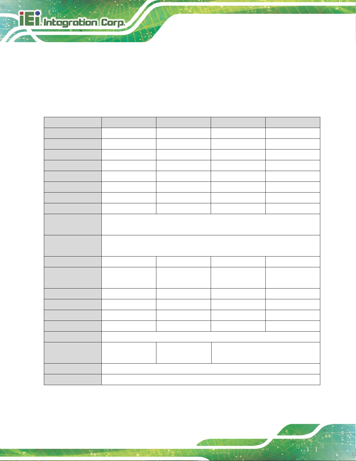
1.7 Technical Specifications
The specifications for the FLEX-BX200-Q370 box PCs are listed below.
FLEX-BX200-Q370
CPU
Chipset Intel® Q370
BIOS AMI UEFI BIOS
Memory
Graphics Engine
Display Output
Ethernet
Super I/O Fintek F81866
Embedded Controller ITE IT8528E
8th Generation LGA1151 Intel® Core™ i7/ i 5/i3 and Pentium®
processor (65W/35W)
Two 288-pin 2666/2400 MHz dual-channel DDR4 SDRAM DIMM
slots (system max. 64 GB)
-Intel® HD Graphics Gen 9 Engines with low power 16 execution
units, supports DX2015, OpenGL 5.X and OpenCL2.x, ES 2.0
1 x HDMI (external)
1 x LVDS (internal)
1 x iDP (internal)
LAN1: Intel® I211AT Ethernet controller
LAN2: Intel® I211AT Ethernet controller
4 x Hot-swappable SATA 6G/s HDD/SSD bay (support RAID
Storage
USB
COM 2 x RS-232 (DB-9, COM1 & COM2)
Audio
Buttons and Indicators
0/1/5/10)
2 x M.2 M-key (2280, PCIe 3.0 x4), support NVMe SSD
6 x USB 3.1 Gen 1 Type-A (external)
1 x USB DOM for QTS Gateway (internal, 2x4 pin header)
Realtek ALC662 HD codec
1 x Line out
1 x Mic in
1 x HDD LED (front panel)
1 x Power button with LED indicator (front panel )
1 x Reset button (rear panel)
1 x AT/ATX mode switch (rear panel)
Page 25

FLEX-BX200-Q370
Page 7
2 x PCIe 3.0 x16 (x8 mode)
Expansions
Thermal
Power supply
2 x PCIe 3.0 x4
(Max. card size: 68 mm x 167 mm)
3 x System fan
1 x CPU fan
AC input ATX power supply
1. 250 W power supply
- Input: 115VAC~230VAC, 50/60Hz
- Output (max.): 3.3V@12A, 5V@14A, 12V@25A,
-12V@0.3A,+5Vsb@3A
2. 350 W power supply (Build to Order)
- Input: 115VAC~264VAC, 50/60Hz
- Output (max.): 3.3V@14A, 5V@16A, 12V @29A,
-12V@0.3A,+5Vsb@3A
-Efficiency: Full load (100%) 87% , Typical load (50%) 90%, Light
load (20%) 87%
Support AT/ATX mode
Chassis Construction Metal housing
Mounting Wall mount, rack mount
Color Black C
Dimensions (LxDxH) 357 mm x 230 mm x 88 mm
Watchdog Timer Software programmable support 1~255 sec. system reset
Vibration
Shock 10G acceleration part to part (11ms)
Operating Temperature
Storage Temperature -30°C ~ 60°C
Operating Humidity 5% ~95%, non-condensing
Table 1-2: Technical Specifications
5~17Hz, 0.1 double amplitude displacement 17~ 640Hz 1.5G
acceleration peak to peak
-20°C ~ 50°C (with SSD and TDP 65W processor)
-20°C ~ 40°C (with HDD or add-on cards without f an)
Page 26
FLEX-BX200-Q370
Page 8
1.8 Optional Panel Kit Specifications
By combining with the FLEX-PLKIT LCD panel, the FLEX-BX200-Q370 can transform into
an all-in-one panel PC. The specifications for the opt ional panel kits are listed below.
1.8.1 15” ~ 18.5” Specifications
LCD Size
Max. Resolution
Brightness (cd/m²)
Contrast Ratio
LCD Color
Pixel Pitch (mm)
Viewing Angle (H/V)
Backlight MTBF
Touchscreen Type
Touch Controller
Video Interface
Dimensions (mm)
(W x H x D)
FLEX-PLKIT-F15 FLEX-PLKIT-FW15 FLEX-PLKIT-F17 FLEX-PLKIT-FW19
15” 15.6" 17” 18.5"
1024 x 768 1366 x 768 1280 x 1024 1366 x 768
450 400 350 400
800:1 500:1 1000:1 1000:1
16.2M 16.2M 16.7M 16.7M
0.29 x 0.29 0.252 x 0.252 0.26 x 0.26 0.3 x 0.3
160°/150° 170°/160° 170°/160° 170°/160°
70,000 hrs 50,000 hrs 50,000 hrs 50,000 hrs
5-wire resistive touch window with anti-glare coating /
Projected capacitive type with 10-point multi-touch and anti-glare coating
Resistive type: Penmount 9000
Projected capacitive type: EETI EXC3000
LVDS LVDS LVDS LVDS
378.5 x 303 x 30 400.1 x 253.3 x 33 408.4 x 341.4 x 31 468.8 x 288.2 x 32.8
Cutout Dimensions
Color
Front Frame
Rear Cover
Mounting
Operating Temp.
Storage Temp.
Humidity
285.6 x 361.1 (mm) 232.3 x 379.1 (mm) 324 x 391 (mm) 257.2 x 447.8 (mm)
PANTONE 296 C PANTONE 296 C PANTONE 296 C PANTONE 296 C
Aluminum Aluminum Aluminum Aluminum
Sheet Metal Sheet Metal Sheet Metal Sheet Metal
Panel mount, Rack mount
-10°C ~ 60°C
(with air flow)
-20°C ~ 70°C
10% ~ 95% (non-condensing)
-10°C ~ 50°C
-10°C ~ 60°C (with air flow)
(with air flow)
Page 27

FLEX-BX200-Q370
Page 9
1.8.1 21.5” ~ 23.8” Specifications
LCD Size
Max. Resolution
Brightness (cd/m²)
Contrast Ratio
LCD Color
Pixel Pitch (mm)
Viewing Angle (H/V)
Backlight MTBF
Touchscreen Type
Touch Controller
Video Interface
Dimensions (mm)
Cutout Dimensions
Color
Front Frame
FLEX-PLKIT-FW22 FLEX-PLKIT-FW24
21.5” 23.8”
1920 x 1080 1920 x 1080
250 250
1000:1 3000:1
16.7M 16.7M
0.25 x 0.25 0.274 x 0.274
170°/160° 178°/178°
30,000 hrs 30,000 hrs
Projected capacitive type with 10-point multi-touch and anti-glare coating
EETI EXC3000
LVDS LVDS
550.4 (W) x 358.4 (H) x 29.8 (D) 600 (W) x 382 (H) x 31 (D)
341 x 533 (mm) 359.6 x 577.6 (mm)
PANTONE 296 C PANTONE 296 C
Aluminum Aluminum
Rear Cover
Mounting
Operating Temp.
Storage Temp.
Humidity
Sheet Metal Sheet Metal
Panel mount
-10°C ~ 50°C (with air flow)
-20°C ~ 60°C
10% ~ 95% (non-condensing)
Page 28

FLEX-BX200-Q370
Page 10
1.9 Dimensions
The dimensions of the FLEX-BX200-Q370 are listed below and shown in Figure 1-5.
See “Appendix E: Panel Kit Dimensions” for the dimensions of the whole FLEX-PLKIT
series.
Figure 1-5: FLEX-BX200-Q370 Dimensions with Mounting Brackets (mm)
Page 29

FLEX-BX200-Q370
Page 11
Chapter
2
2 Unpacking
Page 30
FLEX-BX200-Q370
Page 12
was purchased from or contact an IEI sales
2.1 Unpacking
To unpack the box PC, follow the steps below:
Step 1: Use box cutters, a knife or a sharp pair of scissors that seals the top side of the
external (second) box.
Step 2: Open the external (second) box.
Step 3: Use box cutters, a knife or a sharp pair of scissors that seals the top side of the
internal (first) box.
Step 4: Lift the system out of the boxes.
Step 5: Remove both polystyrene ends, one from each side.
Step 6: Make sure all the components listed in the packing list are present.
2.2 Packing List
NOTE:
If any of the components listed in the checklist below are missing, do
not proceed with the installation. Contact the IEI reseller or vendor the
FLEX-BX200-Q370
representative directly by sending an email to sales@ieiworld.com.
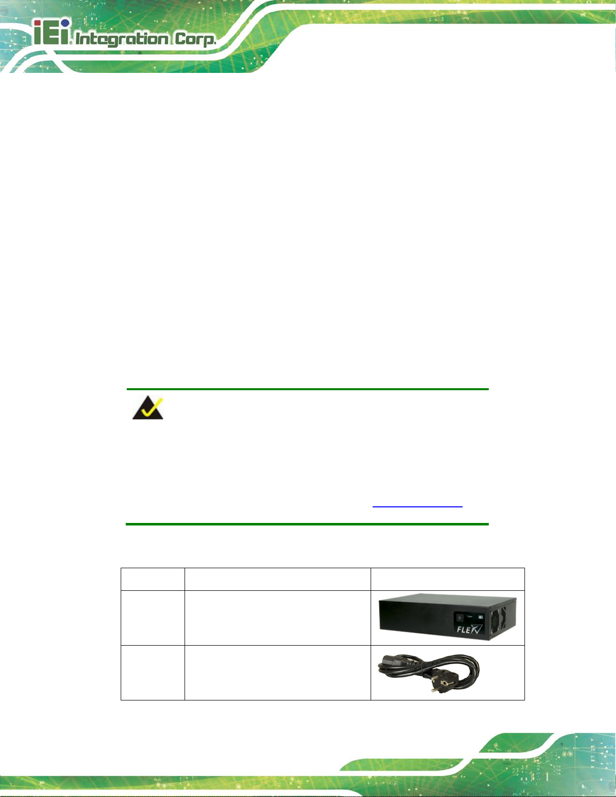
The FLEX-BX200-Q370 box PC is shipped with the following components:
Quantity Item Image
1 FLEX-BX200-Q370 box PC
1 Power cord
Page 31
FLEX-BX200-Q370
Page 13
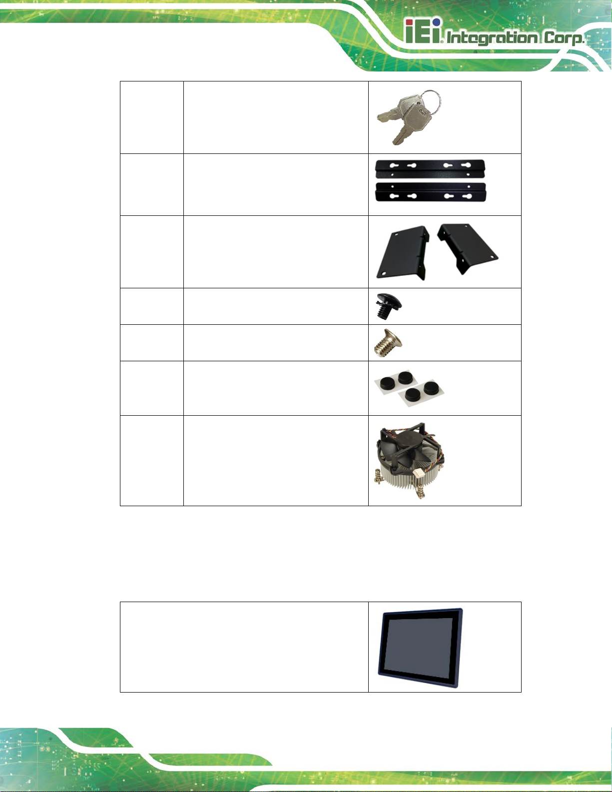
2 Keys for locking HDD cover
2 Wall mount bracket
2 Rack mount bracket
8 Screws (M4*6) for mounting brackets
16 Screws (M3*4) for HDD installation
4 Foot pad
1 CPU cooler
(only for the SKU without CPU)
Table 2-1: Package List
2.3 Optional Items
The following are optional component(s) which m ay be separately purchased:
15" touch LCD for FLEX box PC, P-CAP
(P/N: FLEX-PLKIT-F15/PC-R10)
Page 32

FLEX-BX200-Q370
Page 14
15.6" touch LCD for FLEX box PC, P-CAP
(P/N: FLEX-PLKIT-FW15/PC-R10)
17" touch LCD for FLEX box PC, P-CAP
(P/N: FLEX-PLKIT-F17/PC-R10)
18.5" touch LCD for FLEX box PC, P-CAP
(P/N: FLEX-PLKIT-FW19/PC-R10)
21.5" touch LCD for FLEX box PC, P-CAP
(P/N: FLEX-PLKIT-FW22/PC-R10)
23.8" touch LCD for FLEX box PC, P-CAP
(P/N: FLEX-PLKIT-FW24/PC-R10)
Table 2-2: Optional Items
Page 33

FLEX-BX200-Q370
Page 15
Chapter
3
3 Installation
Page 34

FLEX-BX200-Q370
Page 16
Failure to take ESD precautions during the maintenance of the
may result in permanent damage to the
3.1 Anti-static Precautions
WARNING:
FLEX-BX200-Q370
FLEX-BX200-Q370 and severe injury to the user.
Electrostatic discharge (ESD) can cause serious damage to electronic components,
including the WAFER series motherboard and the power module. (Dry climates are
especially susceptible to ESD.) It is therefore critical that whenever the
FLEX-BX200-Q370 is opened and any electrical component handled, the following
anti-static precautions are strictly adhered to.
Wear an anti-static wristband: Wearing a simple anti-static wristband can
help to prevent ESD from damaging the board.
Self-grounding: Before handling the board, touch any grounded conducting
material. During the time the board is handled, f requently touch any
conducting materials that are connected to the ground.
Use an anti-static pad: When configuring the FLEX-BX200-Q370, place it on
an anti-static pad. This reduces the possibility of ESD damaging the
FLEX-BX200-Q370.
3.2 Installation Precautions
During installation, be aware of the precautions below:
Read the user manual: The user manual provides a complete description of
the FLEX-BX200-Q370, installation instructions and configuration options.
DANGER! Disconnect Power: Power to the FLEX-BX200-Q370 must be
disconnected during the installation process. Fail i ng to disconnect the power
may cause severe injury to the body and/or damage to the system.
Qualified Personnel: The FLEX-BX200-Q370 must be installed and
operated only by trained and qualified personnel. Maintenance, upgrades, or
Page 35

FLEX-BX200-Q370
Page 17
repairs may only be carried out by qualified personnel who are familiar with
the associated dangers.
Air Circulation: Make sure there is sufficient air circulation when i nstalling
the FLEX-BX200-Q370. The FLEX-BX200-Q370’s cooling vents must not be
obstructed by any objects. Blocking the vents can cause overheating of the
FLEX-BX200-Q370. Leave at least 5 cm of clearance around the
FLEX-BX200-Q370 to prevent overheating.
Grounding: The FLEX-BX200-Q370 should be properly grounded. T he
voltage feeds must not be overloaded. A djust the cabli ng and provid e external
overcharge protection per the electrical value s indi cat ed on the label at tached
to the back of the FLEX-BX200-Q370.
3.3 Installation Procedure
To properly install the FLEX-BX200-Q370, the following steps must be followed. Detailed
descriptions of these instructions are list ed in the sections that follow.
Step 1: Unpacking the FLEX-BX200-Q370 box PC
Step 2: Install SATA SSD
Step 3: Install M.2 SSD (optional)
Step 4: Install expansion cards (optional)
Step 5: Mount the FLEX-BX200-Q370
Step 6: Connect the peripheral devices
Step 7: Power the system up Step 0:
Page 36

FLEX-BX200-Q370
Page 18
3.4 Solid-State Drive Installation
Four 2.5” SATA drives can be installed in the FLEX-BX200-Q370. The SATA drives are
installed into the removable hard drive trays protected by a lockable cover on the front
panel. To install the SSD into the system, please follow the steps below.
Step 1: Unlock the HDD cover on the front panel with t he key came with the system.
Figure 3-1: Unlock HDD Cover
Step 2: Open the HDD cover, and you will see four drive t rays (Figure 3-2). Pull out one
of the drive trays.
Figure 3-2: Drive Tray Removal
Page 37

FLEX-BX200-Q370
Page 19
Step 3: Place an SSD onto the drive tray and secure the SSD with the bracket by
inserting four retention screws (M3*4) into t he bottom of the SSD (Figure 3-3).
Figure 3-3: SSD Retention Screws
Step 4: Carefully insert the SSD into the slot on the front panel. Make sure the SATA
connector on the SSD is securely connected to the S ATA connector inside the
chassis.
Figure 3-4: SSD Installation
Step 5: Repeat Step 2 ~ Step 4 described above to install another SSD.
Step 6: Close the HDD cover and lock it with the key. Step 0:
Page 38

FLEX-BX200-Q370
Page 20
To temporarily close the HDD cover, turn the lock knob 90°
procedures are carried out on the
Failing to turn off the system before opening it can cause
NOTE:
counterclockwise by hand to secure the cover.
3.5 Removing the Top Cover
WARNING:
Before any internal installation
system, make sure the system is turned off and cooled down for 15
minutes.
permanent damage to the system and serious or fatal injury to the user.
To access the FLEX-BX200-Q370 internally the top cover must be removed. To remove
the top cover, please follow the steps below.
Step 1: Remove the six retention screws, two on the rear and two on each side.
Figure 3-5: Top Cover Retention Screw Removal
Page 39

FLEX-BX200-Q370
Page 21
CPUs are expensive and sensitive components. When installing the
is installed properly and ensure the correct cooling kit is properly
Step 2: Slide the top cover towards the I/O panel until it is disengaged from the locking
mechanism. Then, lift the top cove r off the chassis. See Figure 3-6.
Figure 3-6: Remove the Top Cover
3.6 Socket LGA1151 CPU Installation (Optional)
WARNING:
CPU please be careful not to damage it in anyway. Make sur e the CPU
installed.
DO NOT touch the pins at the bottom of the CPU. When handling the
CPU, only hold it on the sides.
To install the CPU, follow the steps below.
Step 1: Remove the top cover. See Section 3.5 above.
Step 2: Disengage the load lever by pressing the lever down and slightly outward to
clear the retention tab. Fully open the lever. See Figure 3-7.
Page 40

FLEX-BX200-Q370
Page 22
Figure 3-7: Disengage the CPU Socket Load Lev er
Step 3: Open the socket and remove the protective cov er. The black protective cover
can be removed by pulling up on the tab labeled "Remove". See Figure 3-8.
Figure 3-8: Remove Protective Cover
Step 4: Inspect the CPU socket. Make sure there are no bent pins and make sure the
socket contacts are free of foreign material. I f any debris is foun d, rem ove i t wit h
compressed air.
Page 41

FLEX-BX200-Q370
Page 23
DO NOT touch the pins at the bottom of the CPU. When handling the
Step 5: Orientate the CPU properly. The contact arr ay should be facing the CPU
socket.
WARNING:
CPU, only hold it on the sides.
Step 6: Correctly position the CPU. Match the Pin 1 mark with the cut edge on the
CPU socket.
Step 7: Align the CPU pins. Locate pin 1 and the two orientation notc hes on the CPU.
Carefully match the two orientation notc hes on the CPU with the socket
alignment keys.
Step 8: Insert the CPU. Gently insert the CPU into the socket. If the CPU pins are
properly aligned, the CPU should slide into the CPU socket smoothly. See
Figure 3-9.
Figure 3-9: Insert the Socket LGA1151 CPU
Page 42
FLEX-BX200-Q370
Page 24
installed support bracket prevents the board from
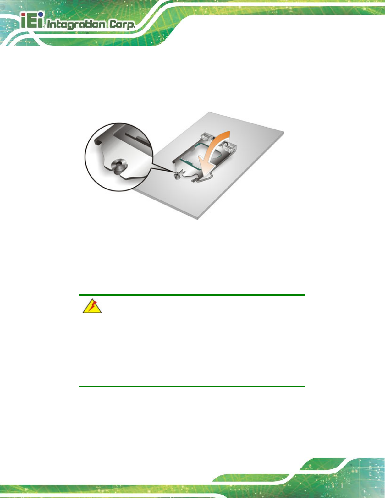
Step 9: Close the CPU socket. Close the load plate and pull the load lever back a little
to have the load plate be able to secure to the knob. Engage the load lever by
pushing it back to its original position (Figure 3-10). There will be some
resistance, but will not require extreme pressure.
Figure 3-10: Close the Socket LGA1151
Step 10: Connect the 12 V power to the board. Connect the 12 V power fr om the power
supply to the board. Step 0:
3.6.1 Socket LGA1151 Cooling Kit Installation (Optional)
WARNING:
DO NOT attempt to install a push-pin cooling fan.
The prebending and is ONLY compatible with captive screw type cooling
fans.
The cooling kit can be bought from IEI. The cool ing kit has a heat sink and fan.
Page 43

FLEX-BX200-Q370
Page 25
sprayed layer of
The thermal paste
between the CPU and the heat sink is important for optimum heat
WARNING:
Do not wipe off (accidentally or otherwise) the prethermal paste on the bottom of the heat sink.
dissipation.
To install the cooling kit, follow the instructions below.
Step 1: A cooling kit bracket is pre-installed on the rear of the motherboard.
Step 2: Place the cooling kit onto the socket LGA1151 CPU. Make sure the CPU
cable can be properly routed when the cooling kit i s installed.
Step 3: Mount the cooling kit. Gently place the cooling kit on top of the CPU. Make
sure the four threaded screws on the corners of the cooling kit properly pass
through the holes of the cooling kit bracket .
Step 4: Tighten the screws. Use a screwdriver to tighten the four screws. In a diagonal
pattern, tighten each screw a few turns then move to the next one, until they are
all secured. Do not overtighten the screws.
Step 5: Connect the fan cable. Connect the cooling kit fan cable to the CPU fan
connector on the FLEX-BX200-Q370. Carefully route the cable and avoid heat
generating chips and fan blades.Step 0:
Page 44

FLEX-BX200-Q370
Page 26
that feature the same capacity, timings, voltage, number of ranks and
3.7 DIMM Installation (Optional)
To install a DIMM, please follow the steps below and refer to Figure 3-11.
Figure 3-11: DIMM Installation
Step 1: Remove the top cover. See Section 3.5 above.
Step 2: Open the DIMM socket handles. Open the two handles outwards as far as
they can. See Figure 3-11.
Step 3: Align the DIMM with the socket. Align the DIMM so the notch on the memory
lines up with the notch on the memory socket. See Figure 3-11.
Step 4: Insert the DIMM. Once aligned, press down until the DIMM i s properly seated.
Clip the two handles into place. See Figure 3-11.
Step 5: Removing a DIMM. To remove a DIMM, push both handles outward. The
memory module is ejected by a mechanism in t he socket.Step 0:
CAUTION:
For dual channel configuration, install two identical memory modules
the same brand.
Page 45

FLEX-BX200-Q370
Page 27
3.8 M.2 SSD Installation (Optional)
The two M.2 M-key slots allow installation of M.2 2280 cards. To install an M.2 card,
please follow the steps below.
Step 1: Remove the top cover. See Section 3.5 above.
Step 2: Locate the M.2 slot as shown in Figure 3-12.
Figure 3-12: M.2 Slot Locations
Step 3: Remove the on-board retention screw as shown in Figure 3-13.
Figure 3-13: Removing the M.2 Module Retention Screw
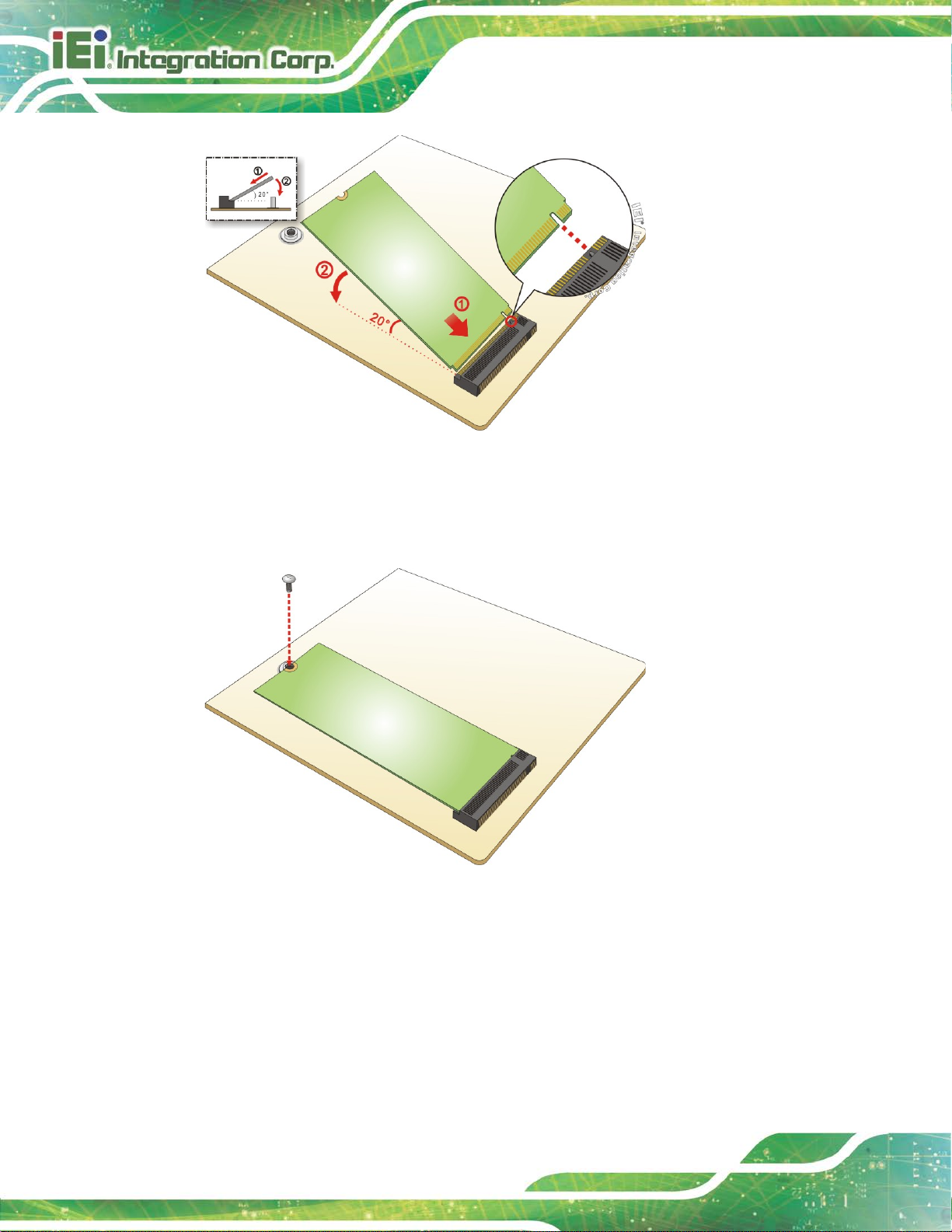
Step 4: Line up the notch on the module with the notch on the slot. Slide t he M.2 module
into the socket at an angle of about 20º (Figure 3-14).
Page 46
FLEX-BX200-Q370
Page 28
Figure 3-14: Inserting the M.2 Module into the Slot at an Angle
Step 5: Push the M.2 module down and secure it with the previously removed retention
screw (Figure 3-15).
Figure 3-15: Securing the M.2 Module
Step 6: Re-install the top cover and secure it with the six retention screws previously
removed.
Page 47
FLEX-BX200-Q370
Page 29
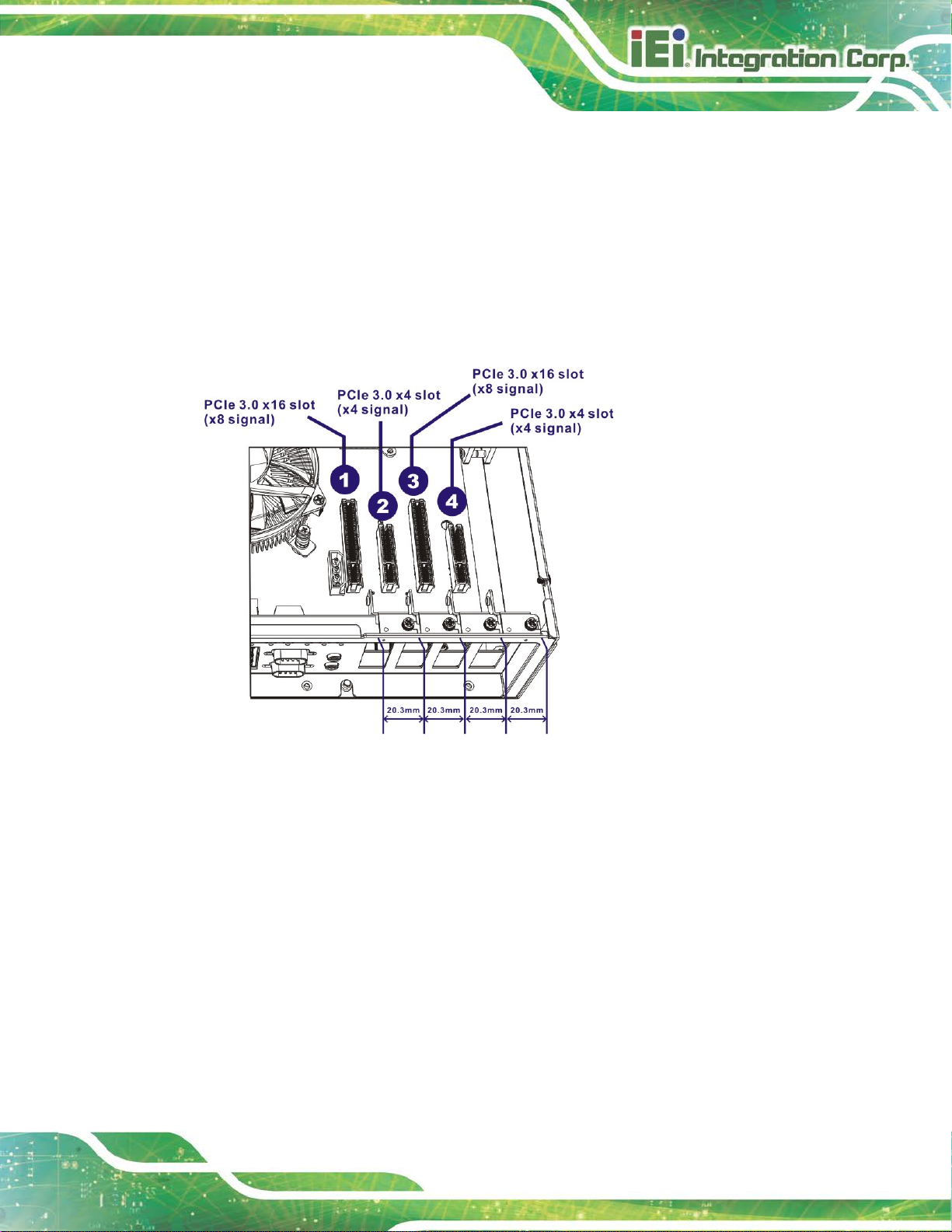
3.9 Expansion Card Installation (Optional)
The FLEX-BX200-Q370 supports multiple PCIe slots which are compatible with standard
low-profile add-on cards, including two PCIe 3.0 x16 (x8 mode) and t wo PCIe 3. 0 x4 slot s.
To install an expansion card, follow the step s below.
Step 1: Remove the top cover. See Section 3.5 above.
Step 2: Locate an empty PCIe slot.
Figure 3-16: PCIe Slot Locations
Step 3: Remove the blank bracket panel on the back of the FLEX-BX200-Q370 that
aligns with the empty PCIe slot. Save this bra cket screw.
Page 48

FLEX-BX200-Q370
Page 30
Figure 3-17: Blank Bracket Screw Removal
Step 4: Align the expansion card to a PCIe slot . Press down gently, but firmly, to seat the
expansion card correctly in the slot.
Step 5: Install the bracket screw to secure the expansion card to the system chassis.
Figure 3-18: Install and Secure Expansion Card
Page 49

FLEX-BX200-Q370
Page 31
Step 6: Re-install the top cover and secure it with the six retention screws previously
removed.
3.10 Mounting the System
The following sections describe the mounting methods supported by the
FLEX-BX200-Q370.
3.10.1 Wall Mount
To mount the box PC onto a wall or some other surface using the two mounting brackets,
please follow the steps below.
Step 1: Turn the box PC over.
Step 2: Align the two retention screw holes in each bracket with the retention screw
holes on the sides of the bottom surface.
Step 3: Secure the brackets to the system by inserti ng two retention screws (M4*6) into
each bracket (Figure 3-19).
Figure 3-19: Mounting Bracket Retention Screws
Step 4: Drill holes in the intended installation surf ace a ccording to the bracket
dimensions listed below.
Page 50

FLEX-BX200-Q370
Page 32
Figure 3-20: Mounting Bracket Retention Screws
Step 5: Align the mounting holes in the sides of the mount ing brackets with the predrilled
holes in the mounting surface.
Step 6: Insert retention screws into each bracket to secure the sy st em to the wall.
Step 0:
Page 51

FLEX-BX200-Q370
Page 33
3.10.2 Rack Mount
The 2U chassis of the box PC is designed to support 19” rack mount. To mount the box
PC onto a rack, please follow the steps below.
Step 1: Secure the rack mount brackets to the system by i nserting two retention screws
(M4*6) into each bracket.
Figure 3-21: Install Rack Mount Bracket
Step 2: Slide the box PC with the attached rack mount brackets into a rack.
Step 3: Once the box PC has been properly inserted into the rack, secure the front of
the rack mount bracket to the front of the rack.
Figure 3-22: Mounting Bracket Retention Screws
Page 52

FLEX-BX200-Q370
Page 34
3.11 Converting to Panel PC (Optional)
By combining with the FLEX-PLKIT LCD panel, the FLEX-BX200-Q370 can be converted
to a panel PC. To install the FLEX-BX200-Q370 box PC onto a FLEX-PLKIT LCD panel,
follow the steps below.
Step 1: Face the monitor panel down and place it onto a flat surface. Place the box PC
on the side with the bottom panel facing up.
Step 2:
Loosen the cover retention screw located in t he bottom panel of the box PC,
and remove the cover to expose the wiring connection hole.
Fasten two positioning screws onto the box PC as shown in the figure below.
Page 53
FLEX-BX200-Q370
Page 35
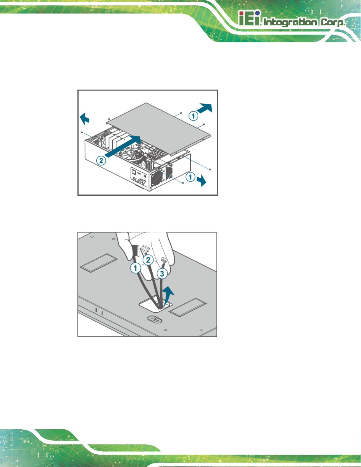
Step 3: Turn the box PC over. Remove the six top cover retention screws.
Slide the top cover towards the I/O panel, and the n l ift the top cover off the
box PC.
Step 4: Gently pull out the three cables from the rear of the panel kit.
Page 54

FLEX-BX200-Q370
Page 36
Step 5: Carefully feed the three cables into the box P C through the wiring connection
hole on the bottom panel.
Step 6: Align the two positioning screws (M4*6) fastened on the bottom panel of the box
PC with the slotted holes located in the rear panel of the panel kit. Gently place
the box PC onto the panel kit, while ensure the screws are inserted into the
slotted holes. Push the box PC towards left to lock it into position.
Page 55

FLEX-BX200-Q370
Page 37
Step 7: Use four retention screws (M4*7) to secure the box PC with the panel kit.
Step 8: Connect the cables to the corresponding connectors on the motherboard.
LVDS connector (LVDS1, 40-pin)
Inverter connector (INV1, 6-pin)
Touch connector (JUSB1, 4-pin)
For connector pinouts, see Chapter 6.
Page 56

FLEX-BX200-Q370
Page 38
ON
OFF
ON
OFF
OFF
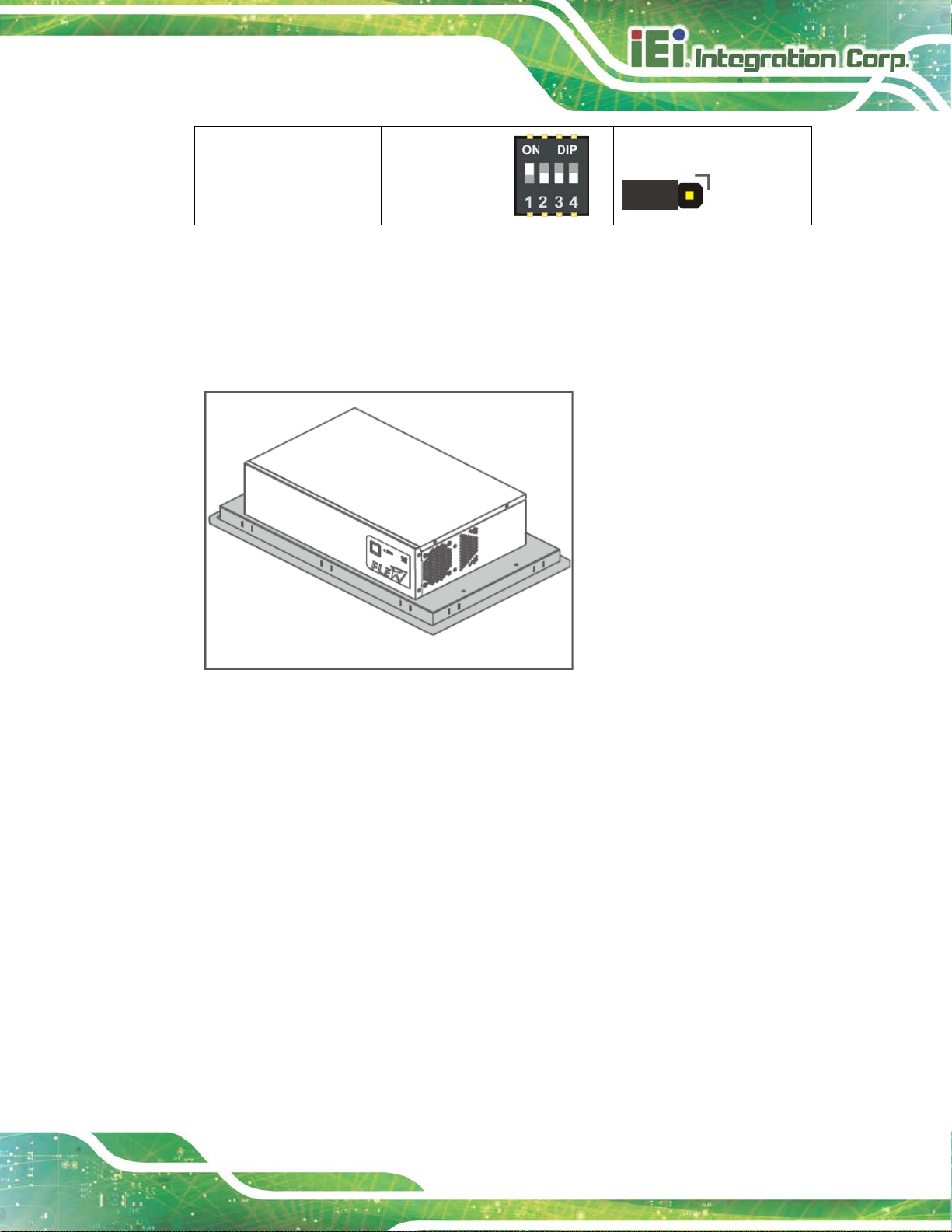
Step 9: Configure jumper and switch in box PC. Locate the panel resolut ion switch
(SW1) and the panel voltage jumper (J_PW1) on t he m otherboard. Configure
the switch and the jumper for the installed panel kit according to the description
listed in the following table.
FLEX-PLKIT-F15
FLEX-PLKIT-FW15 ON-ON-ON-
FLEX-PLKIT-F17 ON-OFF-OFF-
FLEX-PLKIT-FW19 ON-ON-ON-
Panel Resolution (SW1) Panel Voltage (J_PW1)
ON-OFF-ON-
Short 1-2 (+3.3V, default)
Short 2-3 (+5V)
Short 2-3 (+5V)
Short 2-3 (+5V)
Short 2-3 (+5V)
FLEX-PLKIT-FW22 ON-OFF-OFF-
Page 57
FLEX-BX200-Q370
Page 39
OFF
Short 2-3 (+5V)
FLEX-PLKIT-FW24 ON-OFF-OFF-
Table 3-1: Panel Resolution and Voltage Jumper Settings
Step 10: Re-install the top cover of the box PC with the six retention screws previously
removed.
Page 58
FLEX-BX200-Q370
Page 40
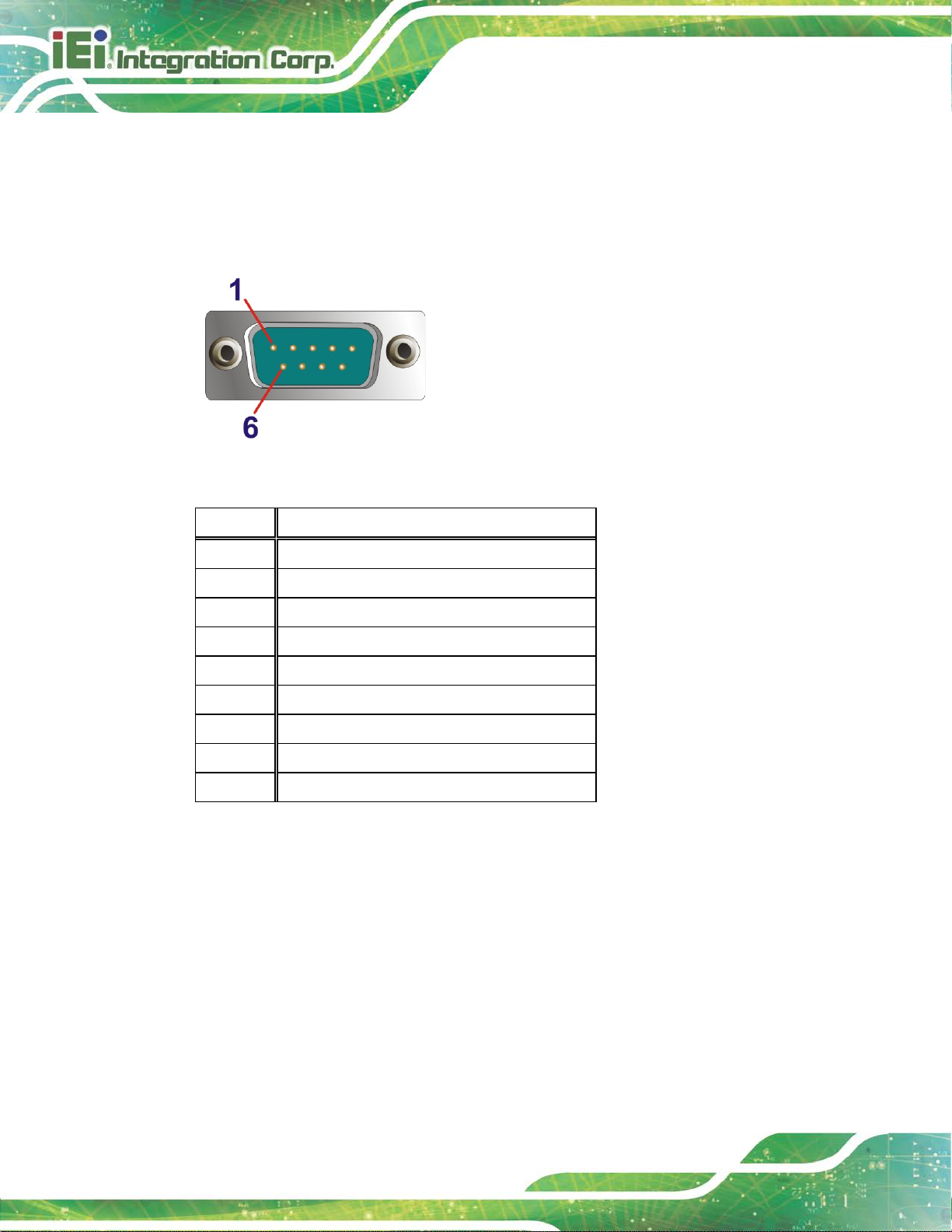
3.12 COM Port Connection
The FLEX-BX200-Q370 has two DB-9 connectors for RS-232 serial port connection. The
pinouts for the RS-232 connectors (COM1and COM2) are listed in the figure and table
below.
Figure 3-23: RS-232 Connector (COM1, COM2)
PIN NO. DESCRIPTION
1 DCD
2 RX
3 TX
4 DTR
5 GND
6 DSR
7 RTS
8 CTS
9 RI
Table 3-2: RS-232 Connector Pinouts
Page 59
FLEX-BX200-Q370
Page 41
Make sure a power supply with the correct input voltage is being fed into
3.13 Power-On Procedure
3.13.1 Installation Checklist
WARNING:
the system. Incorrect voltages applie d to the system may cause damage to
the internal electronic components and may also cause injury to the user.
To power on the box PC please make sure of the foll owing:
The top cover is installed
All peripheral devices are connected
The power cables are plugged in
The system is securely mounted
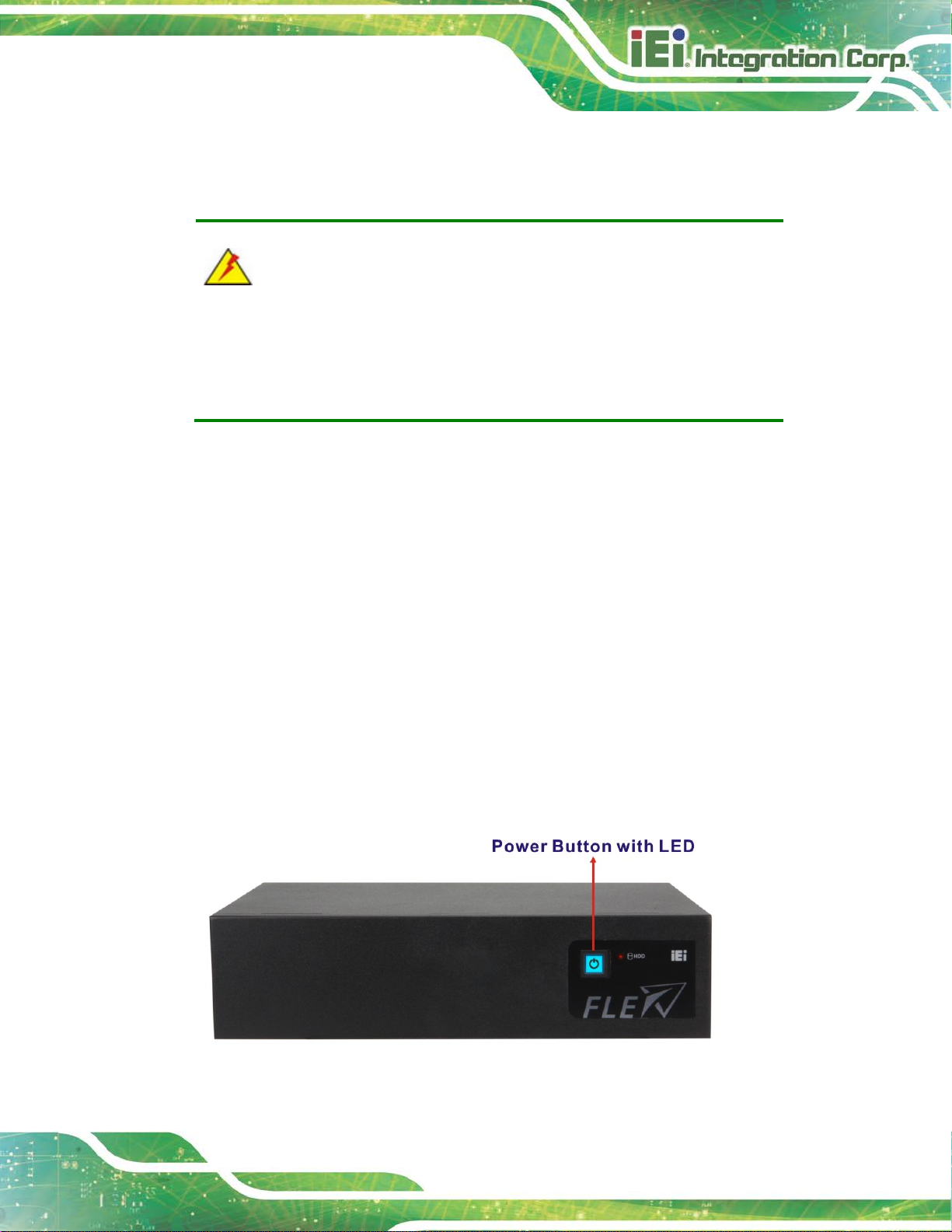
3.13.2 Power-on Procedure
To power-on the FLEX-BX200-Q370 please follow the steps below:
Step 1: Connect the power source to the power inlet on the rear panel.
Step 2: Short-press the power button on the front panel to power up the syst em . The
power LED lights on in blue (Figure 3-24).Step 0:
Figure 3-24: Power Button
Page 60
FLEX-BX200-Q370
Page 42
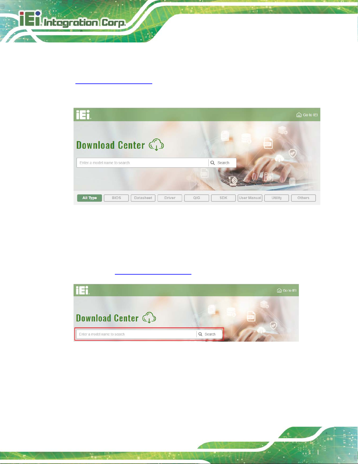
3.14 Software Installation
All the drivers for the FLEX-BX200-Q370 are available on IEI Resource Download Center
(https://download.ieiworld.com
relevant software, utilities, and documentati on.
Figure 3-25: IEI Resource Download Center
). Type FLEX-BX200-Q370 and press Enter to find all the
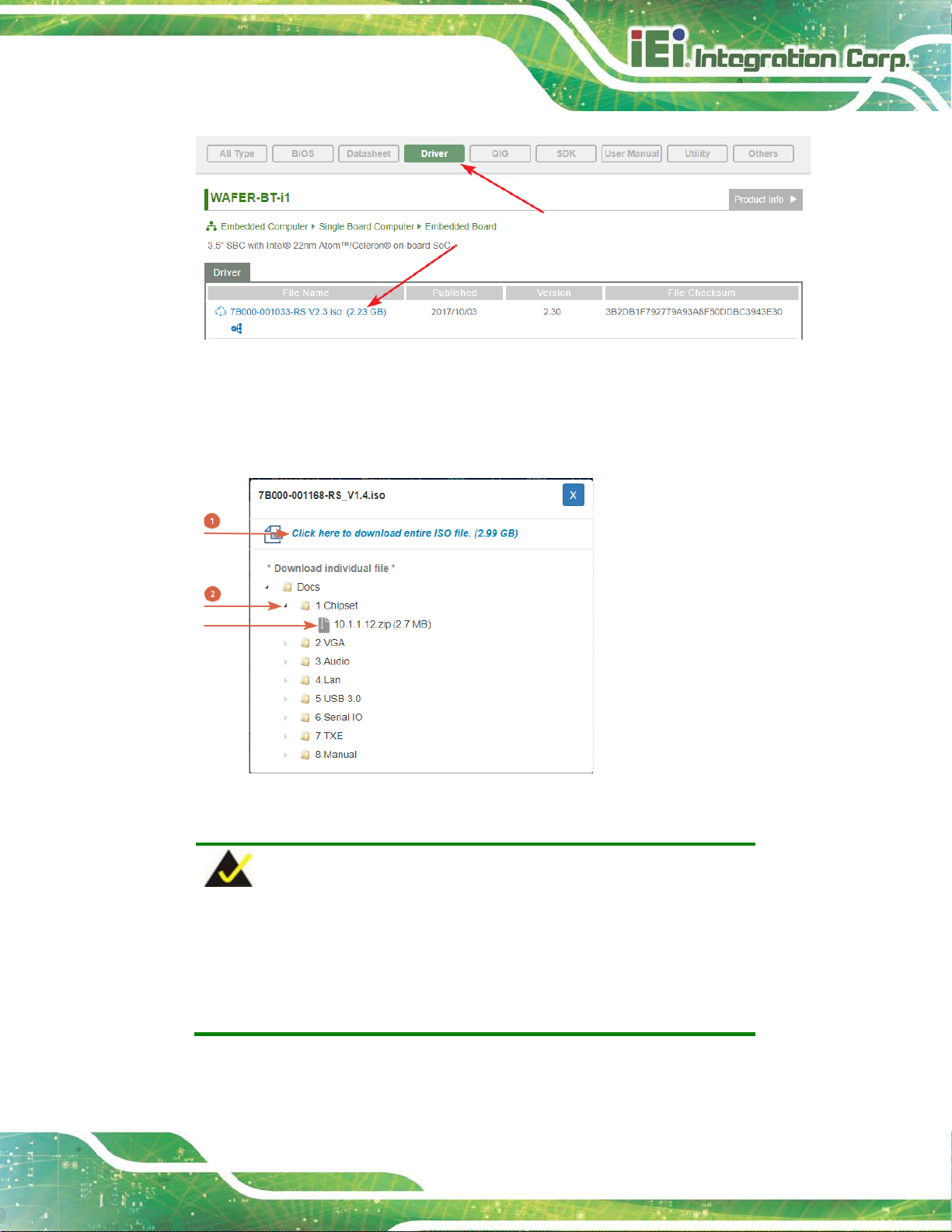
3.14.1 Driver Download
To download drivers from IEI Resource Download Center, follow the steps below.
Step 1: Go to https://download.ieiworld.com
Step 2: All product-related software, utilities, and documentation will be listed. You can
choose Driver to filter the result.
. Type FLEX-BX200-Q370 and press Enter.
Page 61
FLEX-BX200-Q370
Page 43
its content. On Windows 7 system, an additional tool (such as Virtual
Step 3: Click the driver file name on the page and you will be prompted with the
following window. You can download the entire ISO file (
arrow to find an individual driver and click the file name to download (
), or click the small
).
NOTE:
To install software from the downloaded ISO image file in Windows 8,
8.1 or 10, double-click the ISO file to mount it as a virtual drive to view
CD-ROM Control Panel from Microsoft) is needed to mount the file.
Page 62
FLEX-BX200-Q370
Page 44
Irrecoverable data loss occurs if a working drive is removed when
physical connections of all SATA disk drives. Drive locations can be
Do not accidentally disconnect the SATA drive cables. Carefully route
Make sure the SATA drives are EXACTLY the same when they are
3.15 RAID Configuration
The FLEX-BX200-Q370 can provide data protection for serial ATA (SATA) disks via the
Intel® Rapid Storage Technology. To access the Intel
follow the steps below.
WARNING!
trying to remove a failed drive. It is strongly recommended to mark the
identified by attaching stickers to the drive bays. If a drive member of a
RAID array should fail, the failed drive can then be correctly identified.
®
Rapid Storage Technology, please
CAUTION!
the cables within the chassis to avoid system down t i me.
Step 1: Connect SATA drives to the system. Connect two or more SATA drives to the
system. Make sure the drives have the same capacity, are the same type and
have the same speed.
NOTE:
configured in a RAID configuration. If they are not the same size, disk
drive capacity is sacrificed and overall performance affected.
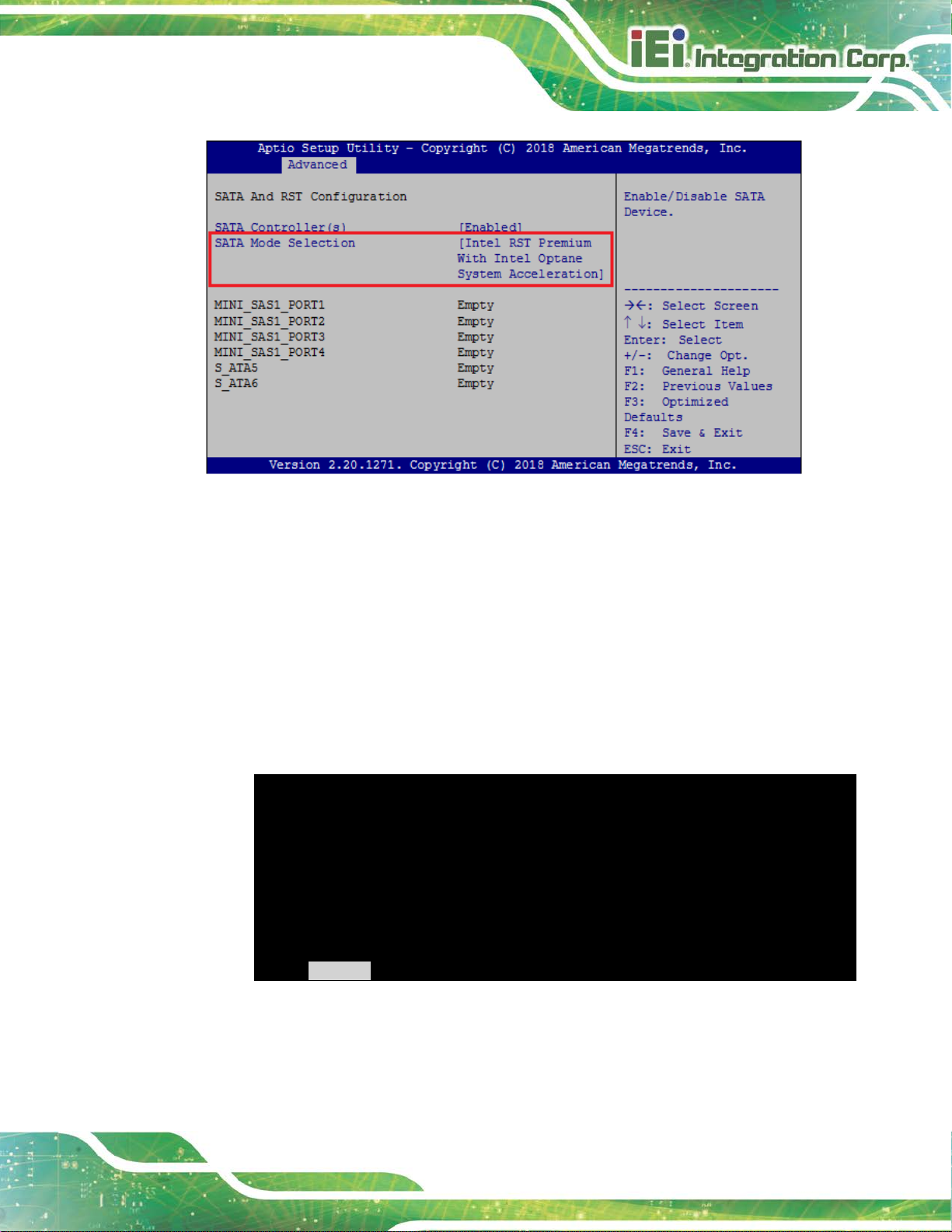
Step 2: Enable SATA drives in BIOS. St art the computer and access the BIOS setup
program. Go to Chipset PCH-IO Configuration SATA Co nfiguration
SATA Mode Selection. Enable RAID support for all SATA devices.
Page 63
FLEX-BX200-Q370
Page 45
Press <CTRL+I> to enter Configuration Utility…
Figure 3-26: RAID Configuration –BIOS Setting
Step 3: Save and Exit BIOS. After the SATA support option is enabled, save and exi t
the BIOS.
Step 4: Reboot the system. Reboot the system after saving and exiting the BIOS.
Step 5: Press Ctrl+I. during the system boot process, press Ctrl+I when prom pted to
enter the RAID configuration software.
Intel(R) Rapid Storage Technology – Option ROM – 15.2.0.2740
Copyright (C) Intel Corporation. All rights reserved.
RAID Volumes:
None defined.
Physical Devices:
ID Device Model Serial # Size Type/Status(Vol ID)
1 256GB SATA Flash 076616F100208548 23.4GB Non-RAID Disk
2 256GB SATA Flash 077302EF00503528 23.4GB Non-RAID Disk
Page 64

FLEX-BX200-Q370
Page 46
Intel(R) Rapid Storage Technology – Option ROM – 15.2.0.2748
Copyright (C) Intel Corporation. All rights reserved.
=============================[MAIN MENU]=============================
3. Reset Disks to Non-RAID 6. Exit
======================[DISK/VOLUME INFORMATION]======================
Intel(R) Rapid Storage Technology – Option ROM – 15.2.0.2748
Copyright (C) Intel Corporation. All rights reserved.
=========================[CREATE VOLUME MENU]========================
Name:
Volume1
Intel(R) Rapid Storage Technology – Option ROM – 15.2.0.2748
Copyright (C) Intel Corporation. All rights reserved.
=========================[CREATE VOLUME MENU]========================
Name:
Volume1
Step 6: Configure the RAID settings. Use the Intel® Rapid Storage Technology to
configure the RAID array.
A) Select the option to Create RAID Volume from the Main Menu and press
Enter.
1. Create RAID Volume 4. Recovery Volume Options
2. Delete RAID Volume 5. Acceleration Options
RAID Volumes:
None defined.
B) Press the up/down arrows on the keyboard t o choose the RAID Level and
press Enter . Select the hard drives for the RAID configurati on and press Enter
when done.
RAID Level:
Disks:
Strip Size:
Capacity:
Sync:
RAID0(Stripe)
Select Disks
16KB
238.5 GB
N/A
Create Volume
Step 7: Create RAID V o lume. Highlight Create Volume and press E nter, then choose Y
when the warning prompt appears to create v ol um e.
RAID Level:
Disks:
Strip Size:
Capacity:
Sync:
RAID0(Stripe)
Select Disks
16KB
238.5 GB
N/A
Create Volume
Page 65

FLEX-BX200-Q370
Page 47
Chapter
4
4 BIOS
Page 66

FLEX-BX200-Q370
Page 48
Some of the BIOS options may vary throughout the life cycle of the
4.1 Introduction
The BIOS is programmed onto the BIOS chip. The BIOS setup p rogram allow s changes t o
certain system settings. This chapter outli nes t he options that can be changed.
NOTE:
product and are subject to change without prior notice.
4.1.1 Starting Setup
The UEFI BIOS is activated when the computer is turned on. The setup program can be
activated in one of two ways.
1. Press the D
2. Press the D
appears on the screen. 0.
If the message disappears before the D
again.
ELETE key as soon as the system is turned on or
ELETE key when the “Press Delete to enter SETUP” message
ELETE key is pressed, restart the computer and try
4.1.2 Using Setup
Use the arrow keys to highlight items, press ENTER to select, use the PageUp and
PageDown keys to change entries, press F1 for help and press E
keys are shown in.
Key Function
Up arrow Move to the item above
Down arrow Move to the item below
Left arrow Move to the item on the left hand side
SC to quit. Navigation
Right arrow Move to the item on the right hand side
+ Increase the numeric valu e or m ake changes
Page 67

FLEX-BX200-Q370
Page 49
Key Function
- Decrease the numeric value or make changes
Page up Move to the next page
Page down Move to the previous page
Esc Main Menu – Quit and do not save changes into CMOS
Status Page Setup Menu and Option Page Setup Menu -Exit current page and return to Main Menu
F1 key General help, only for Status Page Setup Menu and Opt ion
Page Setup Menu
F2 key Load previous values
F3 key Load optimized defaults
F4 key Save changes and Exit BIOS
Table 4-1: BIOS Navigation Keys
4.1.3 Getting Help
When F1 is pressed a small help window describing the appropriate keys to use and the
possible selections for the highlighted item appears. To ex it the Help Window press E
the F1 key again.
4.1.4 BIOS Menu Bar
The menu bar on top of the BIOS screen has the foll owing main items:
Main – Changes the basic system configuration.
Advanced – Changes the advanced system settings.
Chipset – Changes the chipset settings.
Security – Sets User and Supervisor Passwords.
Boot – Changes the system boot configuration.
Save & Exit – Selects exit options and loads default settings
SC or
The following sections completely describe the configuration options found in the menu
items at the top of the BIOS screen and listed above.
Page 68

FLEX-BX200-Q370
Page 50
Aptio Setup Utility – Copyright (C) 2018 American Megatrends, Inc.
Main
Advanced
Chipset
Security
Boot
Save & Exit
Version 2.20.1271. Copyright (C) 2018 American Megatrends, Inc.
4.2 Main
The Main BIOS menu (BIOS Menu 1) appears when the BIOS Setup program is entered.
The Main menu gives an overview of the basic syste m i nformation.
BIOS Information
BIOS Vendor American Megatrends
Core Version 5.13
Compliancy UEFI 2.6; PI 1.4
Project Version Z525AR11.ROM
Build Date and Time 08/29/2018 18:27:13
iWDD Vender iEi
iWDD Version Z525ER10.bin
Processor Information
Name CoffeeLake DT
Brand String Intel(R) Core(TM) CPU
i3-8100T CPU @ 3.10GHz
Speed 3100 MHz
ID 0X906EB
Stepping B0
Number of Processors 4Core(s) / 4Thread(s)
Microcode Revision 8E
GT Info GT2 (0x3E91)
IGFX VBIOS Version 1012
Memory RC Version 0.7.1.58
Total Memory 8192 MB
Set the Date. Use Tab to
switch between Data
elements.
----------------------
: Select Screen
↑ ↓: Select Item
Enter: Select
+/-: Change Opt.
F1: General Help
F2: Previous Values
F3: Optimized Defaults
F4: Save & Exit
ESC: Exit
Memory Frequency 2133 MHz
PCH Information
Name CNL PCH-H
PCH SKU Q370
Stepping B0
ME FW Version 12.0.0.1068
ME Firmware SKU Corporate SKU
Access Level Administrator
System Date [Mon 08/17/2018]
System Time [11:10:27]
BIOS Menu 1: Main
Page 69

FLEX-BX200-Q370
Page 51
The Main menu has two user configurable fields:
System Date [xx/xx/xx]
Use the System Date option to set the system date. Manually enter the day, month and
year.
System Time [xx:xx:xx]
Use the System Time option to set the system time. Manually enter the hours, minutes
and seconds.
4.3 Advanced
Use the Advanced menu (BIOS Menu 2) to configure the CPU and peripheral devices
through the following sub-menus:
WARNING!
Setting the wrong values in the sections below may cause the system
to malfunction. Make sure that the settings made are compatible with
the hardware.
Page 70

FLEX-BX200-Q370
Page 52
Aptio Setup Utility – Copyright (C) 2018 American Megatrends, Inc.
Main
Advanced
Chipset
Security
Boot
Save & Exit
ESC: Exit
Version 2.20.1271. Copyright (C) 2018 American Megatrends, Inc.
> CPU Configuration
> Thunderbolt(TM)Configuration
> Trusted Computing
> ACPI Settings
> iWDD H/M Monitor
> F81866 Super IO Configuration
> RTC Wake Settings
> Serial Port Console Redirection
> USB Configuration
> NVMe Configuration
> iEi QTS
> iEi Feature
BIOS Menu 2: Advanced
System ACPI Parameters
----------------------
: Select Screen
↑ ↓: Select Item
Enter: Select
+/-: Change Opt.
F1: General Help
F2: Previous Values
F3: Optimized Defaults
F4: Save & Exit
Page 71

FLEX-BX200-Q370
Page 53
Aptio Setup Utility – Copyright (C) 2018 American Megatrends, Inc.
Advanced
When enabled, a VMM can
Version 2.20.1271. Copyright (C) 2018 American Megatrends, Inc.
4.3.1 CPU Configuration
Use the CPU Configuration menu (BIOS Menu 3) to view detailed CPU specifications or
enable the Intel Virtualization Technolog y.
CPU Configuration
Type Intel(R) Core(TM) CPU
i3-8100T CPU @ 3.10GHz
ID 0x906E8
Speed 3100 MHz
L1 Data Cache 32 kB x 4
L1 Instruction Cache 32 kB x 4
L2 Cache 256 kB x 4
L3 Cache 6 MB
L4 Cache N/A
VMX Supported
SMX/TXT Not Supported
Intel (VMX) Virtualization [Disabled]
Technology
Active Processor Cores [All]
Intel(R) SpeedStep(tm) [Enabled]
C states [Disabled]
utilize the additional
hardware capabilities
provided by Vanderpool
Technology.
----------------------
: Select Screen
↑ ↓: Select Item
Enter: Select
+/-: Change Opt.
F1: General Help
F2: Previous Values
F3: Optimized Defaults
F4: Save & Exit
ESC: Exit
Intel (VMX) Virtualization Technology [Disabled]
Use the Intel (VMX) Virtualization Technology option to enable or disable virtualization
on the system. When combined with third party software, Intel® Virtualization technology
allows several OSs to run on the same system at the same time.
BIOS Menu 3: CPU Configuration
Disabled DEFAULT
Enabled
Disables Intel Virtualizatio n Technology.
Enables Intel Virtualization Technology.
Page 72

FLEX-BX200-Q370
Page 54
Active Processor Cores [All]
Use the Active Processor Cores BIOS option to enable numbers of cores in the
processor package.
All DEFAULT
1
2
3
Intel(R) SpeedStep(tm) [Enabled]
Use the Intel(R) SpeedStep(tm) option to enable or disable the Intel® SpeedStep
Technology which allows more than two frequency ranges to be supported.
Disabled
Enabled DEFAULT
C states [Disabled]
Use the C states option to enable or disable CPU power management which allows CPU
Enable all cores in the processor package.
Enable one core in the processor package.
Enable two cores in the processor package.
Enable three cores in the processor package.
Disables Intel® SpeedStep Technology
Enables Intel® SpeedStep Technology
to go to C states when it is not 100% utilized.
Disabled DEFAULT
Enabled
Disables CPU power management
Enables CPU power management
Page 73
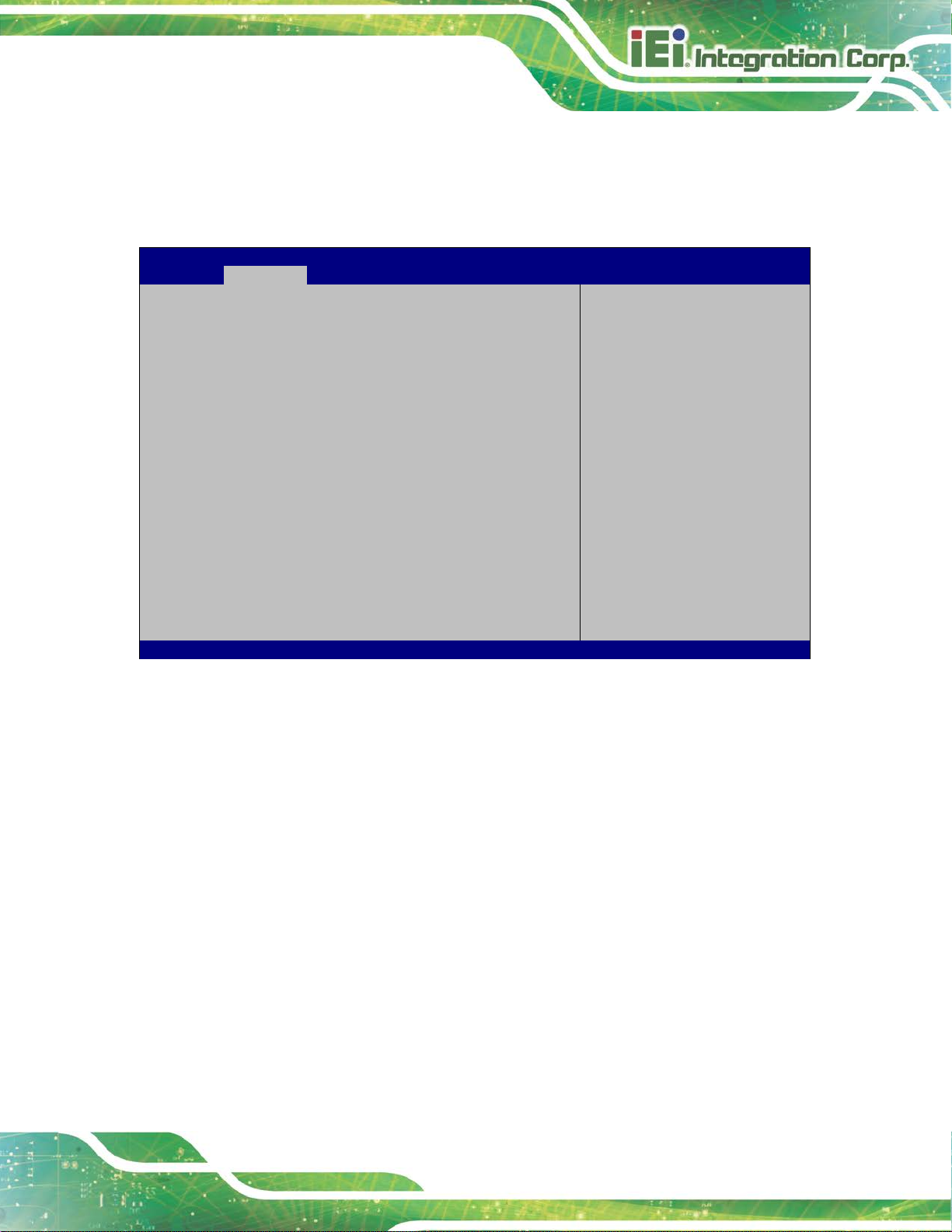
FLEX-BX200-Q370
Page 55
Aptio Setup Utility – Copyright (C) 2018 American Megatrends, Inc.
Advanced
Version 2.20.1271. Copyright (C) 2018 American Megatrends, Inc.
4.3.2 Thunderbolt Configuration
Use the Thunderbolt Configuration menu (BIOS Menu 4) to enable or disable the
support of Thunderbolt™.
Discrete Thunderbolt(TM) Support [Disabled]
BIOS Menu 4: Thunderbolt Configuration
Discrete Thunderbolt(TM) Support [Disabled]
Enables or Disables
Discrete Thunderbolt(TM)
Support. Note: May cause
in-compatibility problems
with insufficient
resources in some pcie
external card.
----------------------
: Select Screen
↑ ↓: Select Item
Enter: Select
+/-: Change Opt.
F1: General Help
F2: Previous Values
F3: Optimized Defaults
F4: Save & Exit
ESC: Exit
Use the Discrete Thunderbolt(TM) Support option to configure support for the
Thunderbolt.
Disabled DEFAULT
Enabled
Thunderbolt support is disabled.
Thunderbolt support is enabled.
Page 74
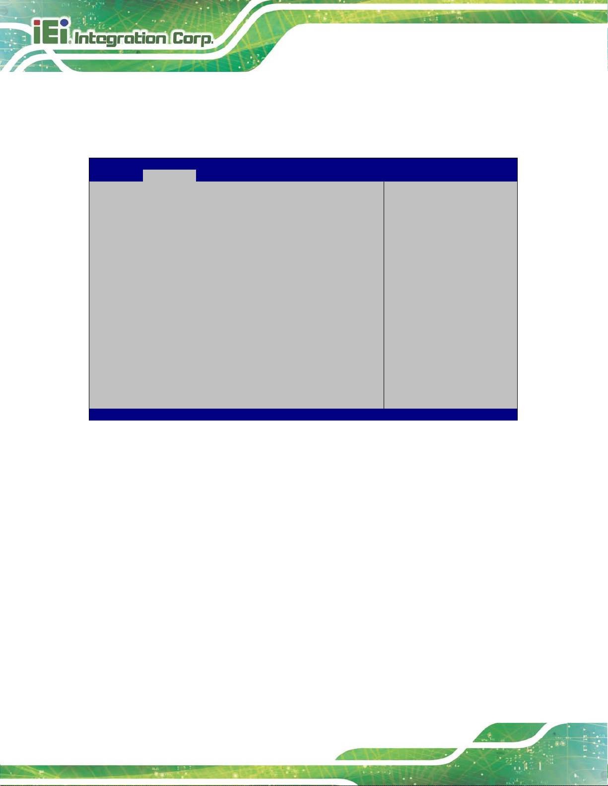
FLEX-BX200-Q370
Page 56
Aptio Setup Utility – Copyright (C) 2018 American Megatrends, Inc.
Advanced
not
Version 2.20.1271. Copyright (C) 2018 American Megatrends, Inc.
4.3.3 Trusted Computing
Use the Trusted Computing menu (BIOS Menu 5) to configure settings related to the
Trusted Computing Group (TCG) Trusted P l atform Module (TPM).
Configuration
Security Device Support [Disable]
NO Security Device Found
BIOS Menu 5: Trusted Computing
Security Device Support [Disable]
Enables or Disables BIOS
support for security
device. O.S. will not
show Security Device.
TCG EFI protocol and
INT1A interface will
be available.
----------------------
: Select Screen
↑ ↓: Select Item
Enter: Select
+/-: Change Opt.
F1: General Help
F2: Previous Values
F3: Optimized Defaults
F4: Save & Exit
ESC: Exit
Use the Security Device Support option to configu re support for the TPM.
Disable DEFAULT
Enable
TPM support is disabled.
TPM support is enabled.
Page 75
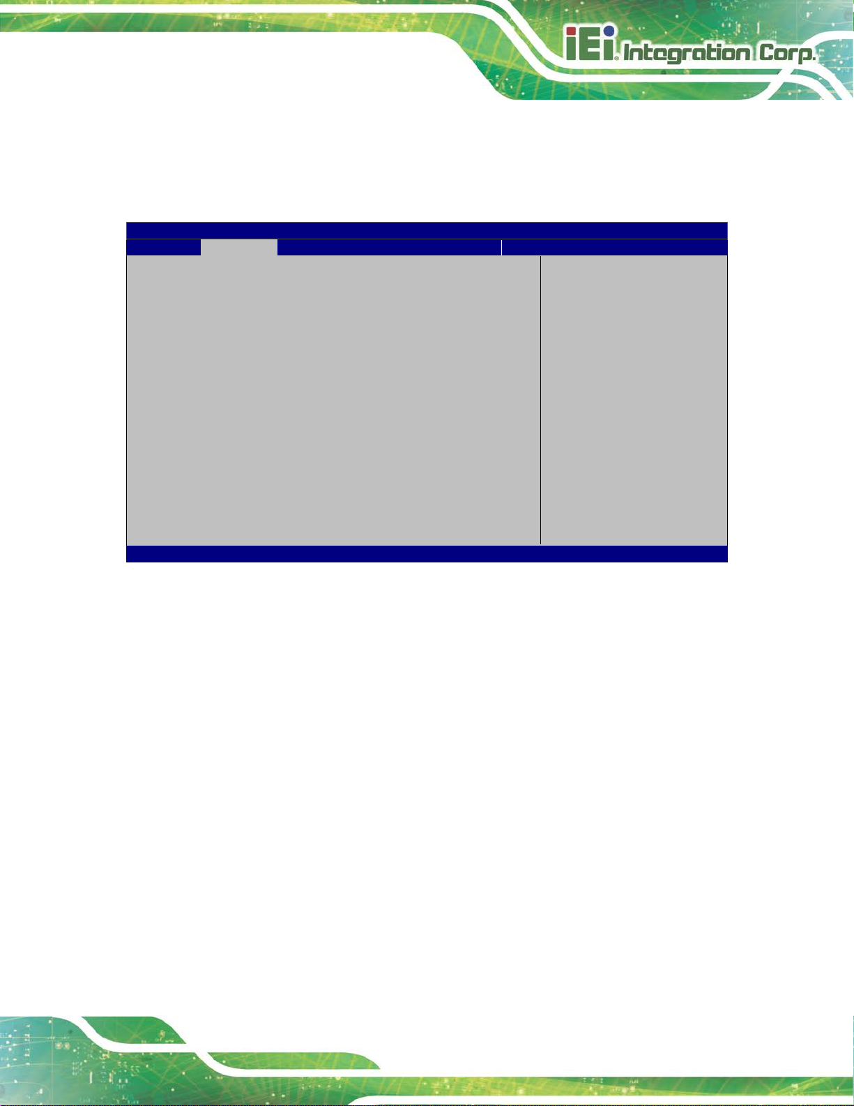
FLEX-BX200-Q370
Page 57
Aptio Setup Utility – Copyright (C) 2018 American Megatrends, Inc.
Advanced
Select ACPI sleep state
when the SUSPEND button
ESC: Exit
Version 2.20.1271. Copyright (C) 2018 American Megatrends, Inc.
The caches are flushed and the CPU is
omputer returns slower to a working
4.3.4 ACPI Settings
The ACPI Settings menu (BIOS Menu 6) configures the Advanced Configuration and
Power Interface (ACPI) options.
ACPI Settings
ACPI Sleep State [S3(Suspend to RAM)]
the system will enter
is pressed.
----------------------
: Select Screen
↑ ↓: Select Item
Enter: Select
+/-: Change Opt.
F1: General Help
F2: Previous Values
F3: Optimized Defaults
F4: Save & Exit
ACPI Sleep State [S3 (Suspend to RAM)]
Use the ACPI Sleep State option to specify the sleep state the system enters when it is
not being used.
BIOS Menu 6: ACPI Configuration
S3 (Suspend to
RAM)
DEFAULT
powered off. Power to the RAM is maintained.
The c
state, but more power is saved.
Page 76

FLEX-BX200-Q370
Page 58
Aptio Setup Utility – Copyright (C) 2018 American Megatrends, Inc.
Advanced
Version 2.20.1271. Copyright (C) 2018 American Megatrends, Inc.
4.3.5 iWDD H/W Monitor
The iWDD H/W Monitor menu (BIOS Menu 7) contains the fan configuration submenu,
and displays the system temperature and CPU fan speed.
PC Health Status
CPU temperature :+35 °C
System temperature :+27 °C
CPU_FAN1 Speed :1601 RPM
SYS_FAN1 Speed :1131 RPM
SYS_FAN2 Speed :1163 RPM
SYS_FAN3 Speed :1238 RPM
CPU_CORE :+0.956 V
+5V :+4.991 V
+12V :+12.000 V
+DDR :+1.196 V
+5VSB :+4.991 V
+3.3V :+3.357 V
+3.3VSB :+3.306 V
> Smart Fan Mode Configuration
BIOS Menu 7: iWDD H/W Monitor
Smart Fan Mode Select
---------------------
: Select Screen
↑ ↓: Select Item
Enter: Select
+/-: Change Opt.
F1: General Help
F2: Previous Values
F3: Optimized Defaults
F4: Save & Exit
ESC: Exit
PC Health Status
The following system parameters and values are shown. The system parameters that are
monitored are:
System Temperatures:
o CPU Temperature
o System Temperature
Fan Speeds:
o CPU Fan Speed
o System Fan Speed
Voltages:
Page 77
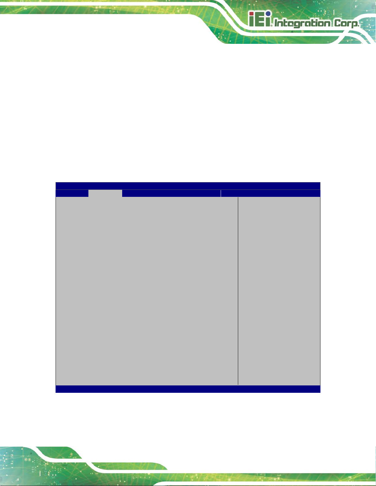
FLEX-BX200-Q370
Page 59
Aptio Setup Utility – Copyright (C) 2018 American Megatrends, Inc.
Advanced
Version 2.20.1271. Copyright (C) 2018 American Megatrends, Inc.
o CPU_CORE
o +5V
o +12V
o DDR
o +5VSB
o +3.3V
o +3.3VSB
4.3.5.1 Smart Fan Mode Configuration
Use the Smart Fan Mode Configuration submenu (BIOS Menu 8) to configure the
CPU/system fan temperature and speed settings.
Smart Fan Mode Configuration
CPU_FAN1 Smart Fan Control [Auto Mode]
Auto mode fan start temperature 50
Auto mode fan off temperature 40
Auto mode fan start PWM 30
Auto mode fan slope PWM 2
SYS_FAN1 Smart Fan Control [Auto Mode]
Auto mode fan start temperature 30
Auto mode fan off temperature 20
Auto mode fan start PWM 40
Auto mode fan slope PWM 3
SYS_FAN2 Smart Fan Control [Auto Mode]
Auto mode fan start temperature 30
Auto mode fan off temperature 20
Auto mode fan start PWM 40
Auto mode fan slope PWM 3
SYS_FAN3 Smart Fan Control [Auto Mode]
Auto mode fan start temperature 30
Auto mode fan off temperature 20
Auto mode fan start PWM 40
Auto mode fan slope PWM 3
Smart Fan Mode Select
---------------------
: Select Screen
↑ ↓: Select Item
Enter: Select
+/-: Change Opt.
F1: General Help
F2: Previous Values
F3: Optimized Defaults
F4: Save & Exit
ESC: Exit
BIOS Menu 8: Smart Fan Mode Configuration
Page 78

FLEX-BX200-Q370
Page 60
The fan spins at the speed set in Manual Mode
using Auto Mode
CPU_FAN1 Smart Fan Control/SYS_FAN Smart Fan Control [Auto Mode]
Use the CPU_FAN1 Smart Fan Control/SYS_FAN Smart Fan Control option to
configure the CPU/System Smart Fan.
Manual Mode
settings.
Auto Mode DEFAULT
The following options can only be set if the CPU/SYS Smart Fan Control option is set to
Auto Mode.
Auto mode fan start temperature
If the CPU temperature is between fan off and fan start, the fan speed change to fan
start PWM. To set a value, Use the + or – key to change the value or enter a decimal
number between 1 and 100.
Auto mode fan off temperature
If the CPU temperature is lower than the value set this option, the fan spe ed change to be
lowest. To set a value, Use the + or – key to change the value or enter a decimal number
The fan adjusts its speed
settings.
between 1 and 100.
Auto mode fan start PWM
Use the Auto mode fan start PWM option to set the PWM start value. Use the + or – key
to change the value or enter a decimal number bet ween 1 and 100.
Auto mode fan slope PWM
Use the Auto mode fan slope PWM option to select the linear rate at which the PWM
mode increases with respect to an increase in temperature. Use the + or – key to change
the value or enter a decimal number between 1 and 8.
Page 79
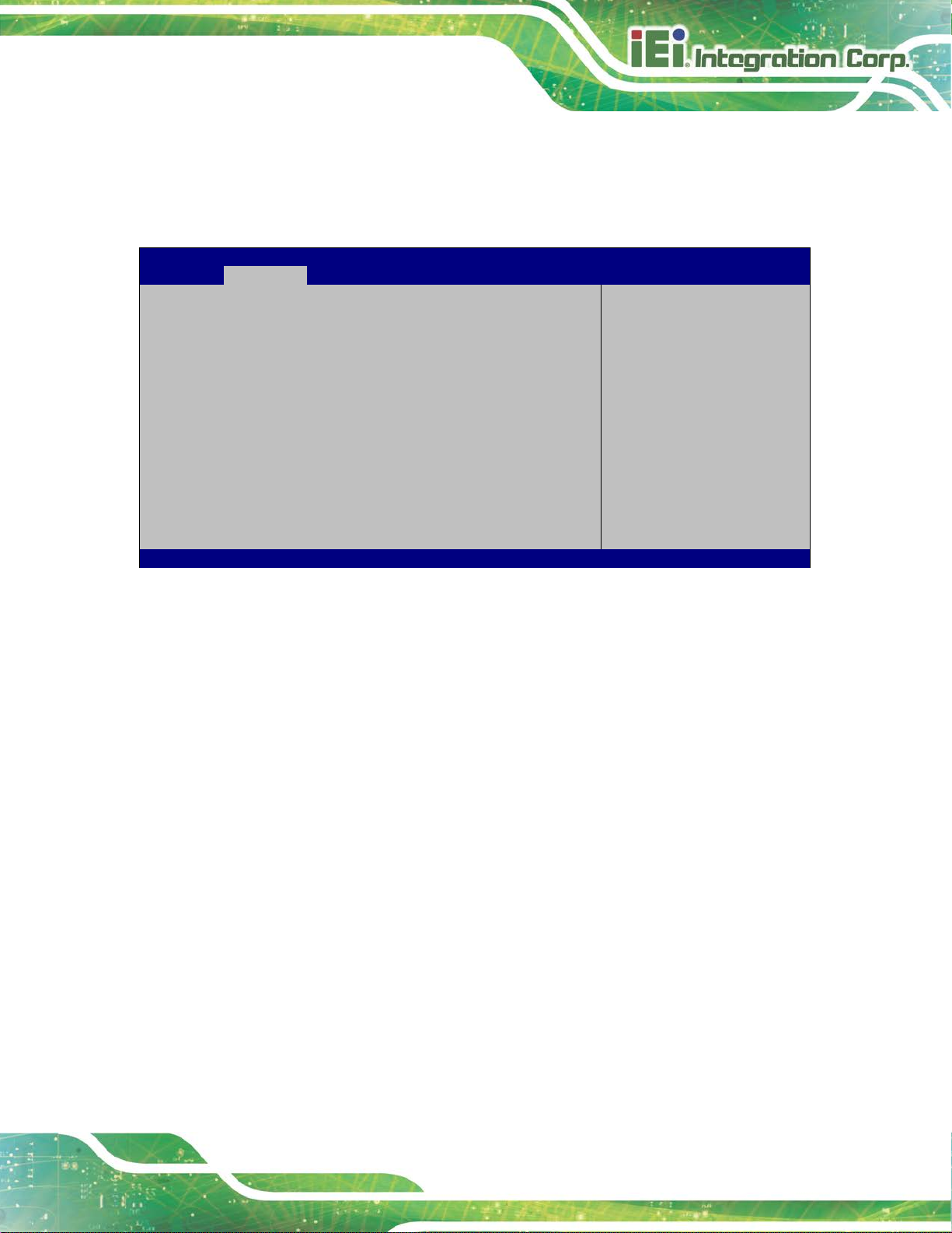
FLEX-BX200-Q370
Page 61
Aptio Setup Utility – Copyright (C) 2018 American Megatrends, Inc.
Advanced
Version 2.20.1271. Copyright (C) 2018 American Megatrends, Inc.
4.3.6 F81866 Super IO Configuration
Use the F81866 Super IO Configuration menu (BIOS Menu 9) to set or change the
configurations for the parallel ports and serial ports.
Super IO Configuration
Super IO Chip F81866
> Serial Port 1 Configuration
> Serial Port 2 Configuration
> Serial Port 3 Configuration
> Serial Port 4 Configuration
> Serial Port 5 Configuration (UART Touch)
Case Open Detection [Disabled]
BIOS Menu 9: F81866 Super IO Configuration
Case Open Beep [Disabled]
Use the Case Open Beep option to enable or disabl e the case open beep function.
Disabled DEFAULT
Disable the case open beep function
Set Parameters of Serial
Port 1 (COMA)
---------------------
: Select Screen
↑ ↓: Select Item
Enter: Select
+/-: Change Opt.
F1: General Help
F2: Previous Values
F3: Optimized Defaults
F4: Save & Exit
ESC: Exit
Enabled
Enable the case open beep function
Page 80

FLEX-BX200-Q370
Page 62
Aptio Setup Utility – Copyright (C) 2018 American Megatrends, Inc.
Advanced
ESC: Exit
Version 2.20.1271. Copyright (C) 2018 American Megatrends, Inc.
4.3.6.1 Serial Port n Configuration
Use the Serial Port n Configuration menu (BIOS Menu 10) to configure the serial port n.
Serial Port n Configuration
Serial Port [Enabled]
Device Settings IO=3F8h; IRQ=4
BIOS Menu 10: Serial Port n Configuration Menu
Serial Port [Enabled]
Use the Serial Port option to enable or disable the serial port.
Disabled
Disable the serial port
Enable or Disable Serial
Port (COM)
---------------------
: Select Screen
↑ ↓: Select Item
Enter: Select
+/-: Change Opt.
F1: General Help
F2: Previous Values
F3: Optimized Defaults
F4: Save & Exit
Enabled DEFAULT
Enable the serial port
Page 81

FLEX-BX200-Q370
Page 63
Aptio Setup Utility – Copyright (C) 2018 American Megatrends, Inc.
Advanced
Version 2.20.1271. Copyright (C) 2018 American Megatrends, Inc.
The real time clock (RTC) cannot generate a wake
every day at the specified time. Besides, the
following options appear with values that can be
4.3.7 RTC Wake Settings
The RTC Wake Settings menu (BIOS Menu 11) enables the system to wake at the
specified time.
Wake system with Fixed Time [Disabled]
BIOS Menu 11: RTC Wake Settings
Wake system with Fixed Time [Disabled]
Use the Wake system with Fixed Time option to enable or disable the system wake on
Enable or disable System
wake on alarm event. When
enabled, System will
wake on the
date::hr::min::sec
specified
----------------------
: Select Screen
↑ ↓: Select Item
Enter: Select
+/-: Change Opt.
F1: General Help
F2: Previous Values
F3: Optimized Defaults
F4: Save & Exit
ESC: Exit
alarm event.
Disabled D
Enabled
EFAULT
event
If selected, the Wake up every day option appears
allowing you to enable to disable the sy st em t o wake
selected:
Wake up date
Wake up hour
Page 82

FLEX-BX200-Q370
Page 64
Aptio Setup Utility – Copyright (C) 2018 American Megatrends, Inc.
Advanced
ESC: Exit
Version 2.20.1271. Copyright (C) 2018 American Megatrends, Inc.
4.3.8 Serial Port Console Redirection
The Serial Port Console Redirection menu (BIOS Menu 12) allows the console
redirection options to be configured. Console redirection allows users to maintain a
system remotely by re-directing keyboard input and text output through the serial port.
Wake up m inute
Wake up sec ond
After setting the alarm, the computer turns itself on
from a suspend state when the alarm goes off.
COM1
Console Redirection [Disabled]
> Console Redirection Settings
COM2
Console Redirection [Disabled]
> Console Redirection Settings
COM3
Console Redirection [Disabled]
> Console Redirection Settings
COM4
Console Redirection [Disabled]
> Console Redirection Settings
Legacy Console Redirection
> Legacy Console Redirection Settings
BIOS Menu 12: Serial Port Console Redirection
Console Redirection
Enable or Disable
---------------------
: Select Screen
↑ ↓: Select Item
Enter: Select
+/-: Change Opt.
F1: General Help
F2: Previous Values
F3: Optimized Defaults
F4: Save & Exit
Page 83

FLEX-BX200-Q370
Page 65
Console Redirection [Disabled]
Use Console Redirection option to enable or disable the con sole redirection function.
Disabled DEFAULT
Enabled
The following options are available in the Console Redirection Settings submenu when
the Console Redirection option is enabled.
Terminal Type [ANSI]
Use the Terminal Type option to specify the remote termi nal type.
VT100
VT100+
VT-UTF8
ANSI DEFAULT
Bits per second [115200]
Disabled the console redirection function
Enabled the console redirection function
The target terminal type is VT100
The target terminal type is VT100+
The target terminal type is VT-UTF8
The target terminal type is ANSI
Use the Bits per second option to specify the serial port transmission speed. The speed
must match the other side. Long or noisy lines may require lower speeds.
Data Bits [8]
Use the Data Bits option to specify the number of data bits.
9600
19200
57600
115200 DEFAULT
7
8 DEFAULT
Sets the serial port transmission speed at 9600.
Sets the serial port transmission speed at 19200.
Sets the serial port transmission speed at 57600.
Sets the serial port transmission speed at 115200.
Sets the data bits at 7.
Sets the data bits at 8.
Page 84

FLEX-BX200-Q370
Page 66
The parity bit is always 1. This option does not
The parity bit is always 0. This option does not
Parity [None]
Use the Parity option to specify the parity bit that can be sent with the data bits for
detecting the transmission errors.
None DEFAULT
Even
Odd
Mark
Space
Stop Bits [1]
Use the Stop Bits option to specify the number of stop bits used to indicate the end of a
serial data packet. Communication with slow devices may require more than 1 stop bit.
1 DEFAULT
No parity bit is sent with the data bits.
The parity bit is 0 if the number of ones in the data
bits is even.
The parity bit is 0 if the number of ones in the data
bits is odd.
provide error detection.
provide error detection.
Sets the number of stop bits at 1.
2
Sets the number of stop bits at 2.
Page 85

FLEX-BX200-Q370
Page 67
Aptio Setup Utility – Copyright (C) 2018 American Megatrends, Inc.
Advanced
Version 2.20.1271. Copyright (C) 2018 American Megatrends, Inc.
4.3.8.1 Legacy Console Redirection Settings
Legacy Serial Redirection Port [COM1]
BIOS Menu 13: Legacy Console Redirection Settings
Legacy Serial Redirection Port [COM1]
Use the Legacy Serial Redirection Port option to select a COM port to display
redirection of legacy OS and legacy OPROM messages. Configuration options are listed
Select a COM port to
display redirection of
Legacy OS and Legacy
OPROM Messages.
---------------------
: Select Screen
↑ ↓: Select Item
Enter: Select
+/-: Change Opt.
F1: General Help
F2: Previous Values
F3: Optimized Defaults
F4: Save & Exit
ESC: Exit
below.
COM1 Default
COM2
COM3
COM4
Page 86

FLEX-BX200-Q370
Page 68
Aptio Setup Utility – Copyright (C) 2018 American Megatrends, Inc.
Advanced
disables legacy support
Version 2.20.1271. Copyright (C) 2018 American Megatrends, Inc.
4.3.9 USB Configuration
Use the USB Configuration menu (BIOS Menu 14) to read USB configuration
information and configure the USB settin gs.
USB Configuration
USB Controllers:
1 XHCI
USB Devices:
1 Keyboard
Legacy USB Support [Enabled]
BIOS Menu 14: USB Configuration
Legacy USB Support [Enabled]
Enables Legacy USB
support. AUTO option
if no USB devices are
connected. DISABLE
option will keep USB
devices available only
for EFI applications.
---------------------
: Select Screen
↑ ↓: Select Item
Enter: Select
+/-: Change Opt.
F1: General Help
F2: Previous Values
F3: Optimized Defaults
F4: Save & Exit
ESC: Exit
Use the Legacy USB Support BIOS option to enable USB mouse and USB keyboard
support. Normally if this option is not enable d, any a t tached USB m ouse o r US B key board
does not become available until a USB comp atible operat ing syst em is fully bo oted with all
USB drivers loaded. When this option is enabled, any attached USB mouse or USB
keyboard can control the system even when there is no USB driver loaded onto the
system.
Enabled DEFAULT
Disabled
Auto
Legacy USB support enabled
Legacy USB support disabled
Legacy USB support disabled if no USB devices are
connected
Page 87

FLEX-BX200-Q370
Page 69
Aptio Setup Utility – Copyright (C) 2018 American Megatrends, Inc.
Advanced
Version 2.20.1271. Copyright (C) 2018 American Megatrends, Inc.
Aptio Setup Utility – Copyright (C) 2018 American Megatrends, Inc.
Advanced
Version 2.20.1271. Copyright (C) 2018 American Megatrends, Inc.
4.3.10 NVMe Configuration
Use the NVMe Configuration (BIOS Menu 15) menu to display the NVMe controller and
device information.
NVMe Configuration
No NVMe Device Found
BIOS Menu 15: NVMe Configuration
4.3.1 IEI QTS
Use the IEI QTS (BIOS Menu 16) menu to display IEI QTS status.
---------------------
: Select Screen
↑ ↓: Select Item
Enter: Select
+/-: Change Opt.
F1: General Help
F2: Previous Values
F3: Optimized Defaults
F4: Save & Exit
ESC: Exit
IEI QTS Active Status [Non-Activated]
BIOS Menu 16: IEI QTS
---------------------
: Select Screen
↑ ↓: Select Item
Enter: Select
+/-: Change Opt.
F1: General Help
F2: Previous Values
F3: Optimized Defaults
F4: Save & Exit
ESC: Exit
Page 88

FLEX-BX200-Q370
Page 70
Aptio Setup Utility – Copyright (C) 2018 American Megatrends, Inc.
Advanced
crashes. Please install
service before enabling
Version 2.20.1271. Copyright (C) 2018 American Megatrends, Inc.
4.3.2 IEI Feature
Use the IEI Feature menu (BIOS Menu 17) to configure One Key Recovery function.
iEi Feature
Auto Recovery Function [Disabled]
BIOS Menu 17: IEI Feature
Auto Recovery Function [Disabled]
Auto Recovery Function
Reboot and recover
system automatically
within 10 min, when OS
Auto Recovery API
this function.
---------------------
: Select Screen
↑ ↓: Select Item
Enter: Select
+/-: Change Opt.
F1: General Help
F2: Previous Values
F3: Optimized Defaults
F4: Save & Exit
ESC: Exit
Use the Auto Reco very Function BIOS option to enable or disable the auto recovery
function of the IEI One Key Recovery.
Disabled DEFAULT
Enabled
Auto recovery function disabled
Auto recovery function enabled
Page 89

FLEX-BX200-Q370
Page 71
Aptio Setup Utility – Copyright (C) 2018 American Megatrends, Inc.
Main
Advanced
Chipset
Security
Boot
Save & Exit
Version 2.20.1271. Copyright (C) 2018 American Megatrends, Inc.
4.4 Chipset
Use the Chipset menu (BIOS Menu 18) to access the PCH IO and System Agent (SA)
configuration menus.
WARNING!
Setting the wrong values for the Chipset B IOS selections in the Chipset
BIOS menu may cause the system to malfunction.
> System Agent (SA) Configuration
> PCH-IO Configuration
BIOS Menu 18: Chipset
System Agent (SA)
Parameters
---------------------
: Select Screen
↑ ↓: Select Item
Enter: Select
+/-: Change Opt.
F1: General Help
F2: Previous Values
F3: Optimized Defaults
F4: Save & Exit
ESC: Exit
Page 90
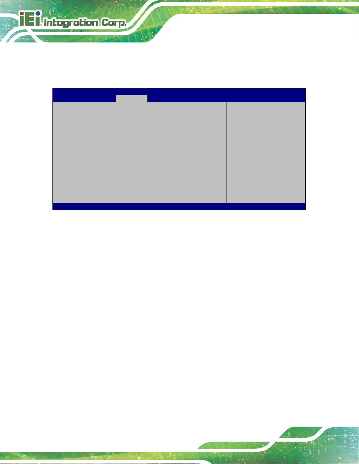
FLEX-BX200-Q370
Page 72
Aptio Setup Utility – Copyright (C) 2018 American Megatrends, Inc.
Chipset
ESC: Exit
Version 2.20.1271. Copyright (C) 2018 American Megatrends, Inc.
4.4.1 System Agent (SA) Configuration
Use the System Agent (SA) Configuration menu (BIOS Menu 19) to configure the
System Agent (SA) parameters.
System Agent (SA) Configuration
VT-d Supported
VT-d [Disabled]
> Memory Configuration
> Graphics Configuration
> PEG Port Configuration
BIOS Menu 19: System Agent (SA) Configuration
VT-d [Disabled]
Use the VT-d option to enable or disable VT-d support .
Disabled DEFAULT
Disables VT-d support.
Memory Configuration
Parameters
---------------------
: Select Screen
↑ ↓: Select Item
Enter: Select
+/-: Change Opt.
F1: General Help
F2: Previous Values
F3: Optimized Defaults
F4: Save & Exit
Enabled
Enables VT -d support.
Page 91

FLEX-BX200-Q370
Page 73
Aptio Setup Utility – Copyright (C) 2018 American Megatrends, Inc.
Chipset
Version 2.20.1271. Copyright (C) 2018 American Megatrends, Inc.
4.4.1.1 Memory Configuration
Use the Memory Configuration submenu (BIOS Menu 20) to view memory information.
Memory Configuration
CHA_DIMM0 Populated & Enabled
Size 8192 MB (DDR4)
Number of Ranks 2
Manufacturer Transcend
CHB_DIMM0 Not Populated/Disabled
BIOS Menu 20: Memory Configuration
---------------------
: Select Screen
↑ ↓: Select Item
Enter: Select
+/-: Change Opt.
F1: General Help
F2: Previous Values
F3: Optimized Defaults
F4: Save & Exit
ESC: Exit
Page 92

FLEX-BX200-Q370
Page 74
Aptio Setup Utility – Copyright (C) 2018 American Megatrends, Inc.
Chipset
Version 2.20.1271. Copyright (C) 2018 American Megatrends, Inc.
4.4.1.2 Graphics Configuration
Use the Graphics Configuration (BIOS Menu 21) menu to configure the video device
connected to the system.
Graphics Configuration
Primary Display [Auto]
Internal Graphics [Enabled]
DVMT Pre-Allocated [32M]
DVMT Total Gfx Mem [MAX]
Primary IGFX Boot Display [VBIOS Default]
Backlight Control Mode [LED]
Backlight Control Type [PWM]
BIOS Menu 21: Graphics Configuration
Primary Display [Auto]
Use the Primary Display option to select the primary graphics co ntroller t he sys tem uses.
The following options are available:
Select which of
IGFX/PEG/PCI Graphics
device should be Primary
Display Or select SG for
Switchable Gfx.
----------------------
: Select Screen
↑ ↓: Select Item
Enter: Select
+/-: Change Opt.
F1: General Help
F2: Previous Values
F3: Optimized Defaults
F4: Save & Exit
ESC: Exit
Auto Default
IGFX
PEG
PCIe
Page 93

FLEX-BX200-Q370
Page 75
Internal Graphics [Enabled]
Use the Internal Graphics option to configure whether to keep IGFX enabled. If user
wants to support dual display by internal graphics and external graphics, this Internal
Graphics option should be set to Enabled and the abov e Primary Display opt ion s hould be
set to IGFX.
Auto
Disabled
Enabled DEFAULT
DVMT Pre-Allocated [32M]
Use the DVMT Pre-Allocated option to set the amount of system memory allo cated to the
integrated graphics processor when the system boots. The system memory allocated can
then only be used as graphics memory, and is no longer available to applications or the
operating system. Configuration options are listed below:
32M Default
64M
DVMT Total Gfx Mem [MAX]
Use the DVMT Total Gfx Mem option to select DVMT5.0 total graphic memory size used
by the internal graphic device. The following opti ons are available:
128M
Auto mode
Disables IGFX.
Enables IGFX.
256M
MAX Default
Primary IGFX Boot Display [VBIOS Default]
Use the Primary IGFX Boot Display option to select the display device used by the
system when it boots. Configuration options are listed below.
VBIOS Default
LVDS
HDMI
IDP1
Default
Page 94
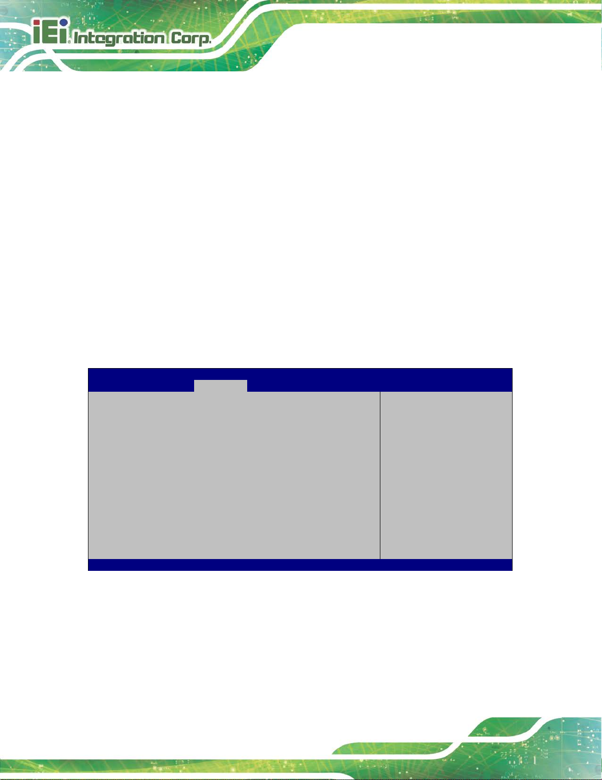
FLEX-BX200-Q370
Page 76
Aptio Setup Utility – Copyright (C) 2018 American Megatrends, Inc.
Chipset
Version 2.20.1271. Copyright (C) 2018 American Megatrends, Inc.
Backlight Control Mode [LED]
Use the Backlight Control Mode option to specify the backlight control mode.
Configuration options are listed below.
LED Default
CCFL
Backlight Control Type [PWM]
Use the Backlight Control Type option to specify the backlight control type.
Configuration options are listed below.
PWM Default
DC
4.4.1.3 PEG Port Configuration
PEG Port Configuration
PCIEX8_1 Not Present
Enable Root Port [Enabled]
Max Link Speed [Auto]
PCIEX8_2 Not Present
Enable Root Port [Enabled]
Max Link Speed [Auto]
> PEG Port Feature Configuration
BIOS Menu 22: PEG Port Configuration
Enable or Disable the
Root Port
----------------------
: Select Screen
↑ ↓: Select Item
Enter: Select
+/-: Change Opt.
F1: General Help
F2: Previous Values
F3: Optimized Defaults
F4: Save & Exit
ESC: Exit
Page 95
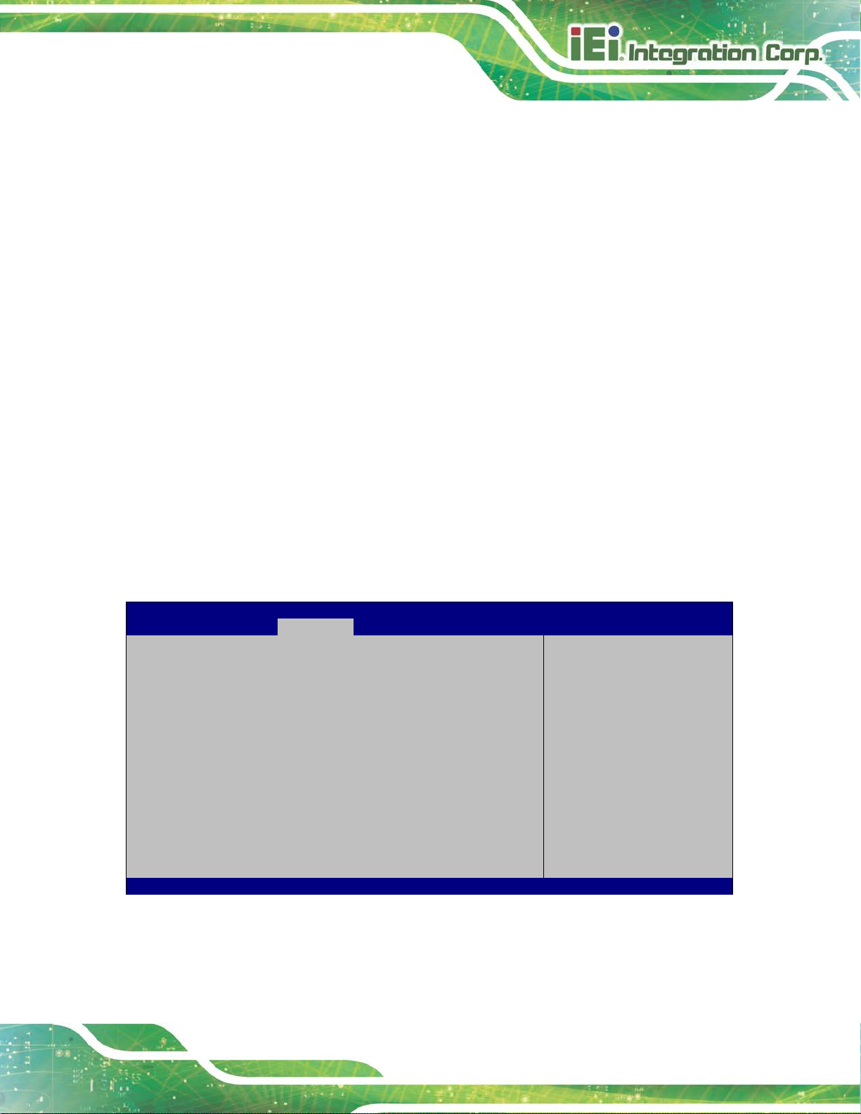
FLEX-BX200-Q370
Page 77
Aptio Setup Utility – Copyright (C) 2018 American Megatrends, Inc.
Chipset
ESC Exit
Version 2.20.1271. Copyright (C) 2018 American Megatrends, Inc.
Enable Root Port [Enabled]
Use the Enable Root Port option to enable or disable the PCI Express (PEG) contr olle r.
Disabled
Enabled DEFAULT
Max Link Speed [Auto]
Use the Max Link Speed option t o select the maximum link speed of the PCI Express slot.
The following options are available:
Auto Default
Gen1
Gen2
Gen3
Disables the PCI Express (PEG) control l er.
Enables the PCI Express (PEG) controller.
4.4.1.3.1 PEG Port Feature Configuration
Use the PEG Port Feature Configuration submenu (BIOS Menu 23) to configure the SA
PCIe settings.
PEG Port Feature Configuration
Detect Non-Compliance Device [Disabled]
BIOS Menu 23: PEG Port Feature Configuration
Detect Non-Compliance
PCI Express Device in PEG
---------------------
: Select Screen
↑ ↓: Select Item
Enter Select
+ - Change Opt.
F1 General Help
F2 Previous Values
F3 Optimized Defaults
F4 Save & Exit
Page 96

FLEX-BX200-Q370
Page 78
Aptio Setup Utility – Copyright (C) 2018 American Megatrends, Inc.
Chipset
applied
Version 2.20.1271. Copyright (C) 2018 American Megatrends, Inc.
Detect Non-Compliance Device [Disabled]
Use the Detect Non-Compliance Device option to det ect non -complian ce PCI e device in
PEG.
Disabled DEFAULT
Enabled
Do not detect non-compliance PCIe device in PEG
Detect non-compliance PCIe device in PEG
4.4.2 PCH-IO Configuration
Use the PCH-IO Configuration menu (BIOS Menu 24) to configure the PCH paramet ers.
PCH-IO Configuration
Auto Power Button Status [Disable (ATX)]
Restore AC Power Loss [Last State]
> PCI Express Configuration
> SATA And RST Configuration
> HD Audio Configuration
Power Saving Function(ERP) [Disabled]
USB Power SW1 [+5V DUAL]
USB Power SW2 [+5V DUAL]
Select AC power state
when power is reafter a power failure.
---------------------
: Select Screen
↑ ↓: Select Item
Enter: Select
+/-: Change Opt.
F1: General Help
F2: Previous Values
F3: Optimized Defaults
F4: Save & Exit
ESC: Exit
BIOS Menu 24: PCH-IO Configuration
Restore AC Power Loss [Last State]
Use the Restore AC Power Loss BIOS option to specify what state the system ret urns to
if there is a sudden loss of power to the system.
Power Off
Power On
Last State DEFAULT
The system remains turned of f
The system turns on
The system returns to its previous state. If it was on, it
turns itself on. If it was off, it remains off.
Page 97

FLEX-BX200-Q370
Page 79
Power Saving Function(ERP) [Disabled]
Use the Power Saving Function(ERP) BIOS option to enable or disable the power
saving function.
Disabled DEFAULT
Enabled
USB Power SW1 [+5V DUAL]
Use the USB Power SW1 BIOS option to configure whether to provide power to the four
external USB 3.1 connectors (L AN1_USB1 & LAN2_USB2) when the system is in S3/S4
sleep state. This option is valid only when the above Power Saving Function (ERP)
BIOS option is disabled.
+5V
DUAL
+5V
USB Power SW2 [+5V DUAL]
DEFAULT
Power saving function is disabled.
Power saving function is enabled. It will reduce power
consumption when the system is of f.
Power is provided to the external USB 3.0 connectors
when the system is in S3/S4 sleep state
Power is not provided to the external USB 3.0
connectors when the system is in S3/S4 sleep st ate
Use the USB Power SW2 BIOS option to configure whether to provide power to the two
external USB 3.1 connectors (USB 1) and the four internal USB 2.0 connectors when the
system is in S3/S4 sleep state. This option is valid only when the above Power Saving
Function (ERP) BIOS option is disabled.
+5V
DUAL
+5V
DEFAULT
Power is provided to the external USB 2.0 connectors
when the system is in S3/S4 sleep state
Power is not provided to the external USB 2.0
connectors when the system is in S3/S4 sleep st ate
Page 98

FLEX-BX200-Q370
Page 80
Aptio Setup Utility – Copyright (C) 2018 American Megatrends, Inc.
Chipset
Enable/Disable PCIEX4_3
Version 2.20.1271. Copyright (C) 2018 American Megatrends, Inc.
4.4.2.1 PCI Express Configuration
Use the PCI Express Configuration menu (BIOS Menu 25) to configure th e PCI Express
and M.2 slots.
PCI Express Configuration
> PCIEX4_1 Slot
> PCIEX4_2 Slot
> M2_M1 Slot
> M2_M2 Slot
Compliance Test Mode [Disabled]
BIOS Menu 25: PCI Express Configuration
Select PCIEX4_3 slot
function.
Slot or SATA Port 3/4.
----------------------
: Select Screen
↑ ↓: Select Item
Enter: Select
+/-: Change Opt.
F1: General Help
F2: Previous Values
F3: Optimized Defaults
F4: Save & Exit
ESC: Exit
Page 99

FLEX-BX200-Q370
Page 81
Aptio Setup Utility – Copyright (C) 2018 American Megatrends, Inc.
Advanced
Control the PCI Express
ESC: Exit
Version 2.20.1271. Copyright (C) 2018 American Megatrends, Inc.
4.4.2.1.1 PCIEX4_1 Slo t, PCIEX4_2 Slot and M.2 Slots
PCIEX4_1 Slot [Enabled]
PCIe Speed [Auto]
BIOS Menu 26: PCIe Slot Configuration Submenu
Root Port.
---------------------
: Select Screen
↑ ↓: Select Item
Enter: Select
+/-: Change Opt.
F1: General Help
F2: Previous Values
F3: Optimized Defaults
F4: Save & Exit
PCIEX4_1 Slot [Enabled]
Use the PCIEX4_1 Slot option to enable or disable the PCIEX4_1 PCI Express slot.
PCIEX4_2 Slot [Enabled]
Use the PCIEX4_2 Slot option to enable or disable the PCIEX4_2 PCI Express slot.
Disabled
Enabled DEFAULT
Disabled
Enabled DEFAULT
Disables the PCIEX4_1 PCI Express slot.
Enables the PCIEX4_1 PCI Express slot.
Disables the PCIEX4_2 PCI Express slot.
Enables the PCIEX4_2 PCI Express slot.
Page 100

FLEX-BX200-Q370
Page 82
M2_M1 Slot [Enabled]
Use the M2_M1 Slot option to enable or disable the M.2 2280 M-key slot.
Disabled
Enabled DEFAULT
M2_M2 Slot [Enabled]
Use the M2_M2 Slot option to enable or disable the M.2 2280 M-key slot.
Disabled
Enabled DEFAULT
PCIe Speed [Auto]
Use this option to select the support type of the PCI Express slots. The following options
are available:
Auto Default
Disables the M.2 2280 M-key slot.
Enables the M.2 2280 M-key slot.
Disables the M.2 2280 M-key slot.
Enables the M.2 2280 M-key slot.
Gen1
Gen2
Gen3
 Loading...