

Page 1

EP-265-910/EP-267-910 Enrich POS System
EP-265-910/ EP-267-910 Enrich POS System
Page i
Page 2

E-265-910/EP-267-910 Enrich POS System
Revision
Date Version Changes
2008-11 1.01
2008-08 1.00
Added current rating of the 12 V output connector and PoweredUSB
connectors
Initial release
Page ii
Page 3

EP-265-910/EP-267-910 Enrich POS System
COPYRIGHT NOTICE
The information in this document is subject to change without prior notice in order to
improve reliability, design and function and does not represent a commitment on the part
of the manufacturer.
In no event will the manufacturer be liable for direct, indirect, special, incidental, or
consequential damages arising out of the use or inability to use the product or
documentation, even if advised of the possibility of such damages.
Copyright
This document contains proprietary information protected by copyright. All rights are
reserved. No part of this manual may be reproduced by any mechanical, electronic, or
other means in any form without prior written permission of the manufacturer.
TRADEMARKS
All registered trademarks and product names mentioned herein are used for identification
purposes only and may be trademarks and/or registered trademarks of their respective
owners.
Page iii
Page 4

E-265-910/EP-267-910 Enrich POS System
Manual Conventions
WARNING!
Warnings appear where overlooked details may cause damage to the equipment or result
in personal injury. Warnings should be taken seriously. Warnings are easy to recognize.
The word “warning” is written as “WARNING,” both capitalized and bold and is followed by
text. The text is the warning message. A warning message is shown below:
WARNING:
This is an example of a warning message. Failure to adhere to warning
messages may result in permanent damage to the EP series or
personal injury to the user. Please take warning messages seriously.
CAUTION!
Cautionary messages should also be heeded to help reduce the chance of losing data or
damaging the EP series. Cautions are easy to recognize. The word “caution” is written as
“CAUTION,” both capitalized and bold and is followed. The italicized text is the cautionary
message. A caution message is shown below:
Page iv
Page 5

EP-265-910/EP-267-910 Enrich POS System
CAUTION:
This is an example of a caution message. Failure to adhere to cautions
messages may result in permanent damage to the EP series. Please
take caution messages seriously.
NOTE:
These messages inform the reader of essential but non-critical information. These
messages should be read carefully as any directions or instructions contained therein can
help avoid making mistakes. Notes are easy to recognize. The word “note” is written as
“NOTE,” both capitalized and bold and is followed by text. The text is the cautionary
message. A note message is shown below:
NOTE:
This is an example of a note message. Notes should always be read.
Notes contain critical information about the EP series. Please take note
messages seriously.
Page v
Page 6

E-265-910/EP-267-910 Enrich POS System
Packing List
NOTE:
If any of the components listed in the checklist below are missing,
please do not proceed with the installation. Contact the IEI reseller or
vendor you purchased the EP series from or contact an IEI sales
representative directly. To contact an IEI sales representative, please
send an email to
The items listed below should all be included in the EP-265-910/EP-267-910 series
package.
1 x EP-265-910/EP-267-910 POS system
1 x Screw set
1 x Power cord
1 x Power supply
1 x Touch pen
1 x User Manual and driver CD
Images of the above items are shown in Chapter 3 on page
sales@iei.com.tw.
29.
Page vi
Page 7

EP-265-910/EP-267-910 Enrich POS System
Table of Contents
1 INTRODUCTION..................................................................................................... 1
1.1 EP-265-910/EP-267-910 ENRICH POS OVERVIEW................................................... 2
1.1.1 Features and Model Variations.......................................................................... 3
1.1.2 Applications ....................................................................................................... 3
1.2 EXTERNAL OVERVIEW ............................................................................................... 4
1.2.1 General Description........................................................................................... 4
1.2.2 Monitor Front Panel.......................................................................................... 4
1.2.3 Monitor Right Side Panel................................................................................... 5
1.2.3.1 I/O Interface Panel...................................................................................... 6
1.2.4 I/O Interface Panel ............................................................................................ 6
1.2.5 Chassis Left Side Panel...................................................................................... 8
1.3 SPECIFICATIONS ......................................................................................................... 8
1.3.1 Preinstalled Hardware Components.................................................................. 8
1.3.2 System Specifications......................................................................................... 9
2 DETAILED SPECIFICATIONS........................................................................... 12
2.1 DIMENSIONS ............................................................................................................ 13
2.1.1 EP-265-910 Dimensions.................................................................................. 13
2.1.2 EP-267-910 Dimensions.................................................................................. 14
2.2 INTEL
2.3 MOTHERBOARD COMPONENTS................................................................................. 15
2.3.1 Memory Support............................................................................................... 15
2.3.2 Storage Capacity.............................................................................................. 16
2.4 EXTERNAL PERIPHERAL INTERFACE CONNECTORS .................................................. 17
2.4.1 Serial Port Connectors .................................................................................... 17
®
CELERON® M PROCESSOR SUPPORT ............................................................ 14
2.3.1.1 Installed Memory...................................................................................... 15
2.3.1.2 Additional Memory................................................................................... 15
2.4.2 LAN Connectivity............................................................................................. 18
2.4.3 External USB Connectors................................................................................ 19
2.4.3.1 Standard USB Connectors ........................................................................ 19
2.4.3.2 PoweredUSB Connectors.......................................................................... 20
Page vii
Page 8

2.4.4 Keyboard and Mouse Connectivity.................................................................. 21
2.5 EP-265-910/EP-267-910 FRONT SIDE..................................................................... 21
2.5.1 Monitor ............................................................................................................ 21
2.5.2 Touch-Screen Module....................................................................................... 22
2.6 GRAPHICS ................................................................................................................ 22
2.6.1 Intel® 910GMLE Integrated Graphics Media Accelerator 900....................... 22
2.6.2 Dual-Display.................................................................................................... 22
2.7 AUDIO...................................................................................................................... 23
2.7.1 High Definition Audio Controller .................................................................... 23
2.7.2 Stereo Speakers ................................................................................................ 23
2.8 SYSTEM POWER ....................................................................................................... 23
2.8.1 Power Mode..................................................................................................... 23
2.8.1.1 AT Power Mode ........................................................................................ 24
2.8.1.2 ATX Power Mode ..................................................................................... 24
E-265-910/EP-267-910 Enrich POS System
2.8.2 Power Supply................................................................................................... 24
2.8.3 Power Connectors............................................................................................ 24
2.8.3.1 Power Input Connector............................................................................. 25
2.8.3.2 Power Output Connector........................................................................... 25
2.8.4 RJ-12 Connectors for Cash Drawer Power..................................................... 25
2.9 WIRELESS ETHERNET............................................................................................... 26
2.10 THERMAL MANAGEMENT....................................................................................... 26
3 UNPACKING .......................................................................................................... 27
3.1 UNPACKING.............................................................................................................. 28
3.1.1 Packing List ..................................................................................................... 29
4 INSTALLATION .................................................................................................... 30
4.1 ANTI-STATIC PRECAUTIONS...................................................................................... 31
4.2 INSTALLATION PRECAUTIONS................................................................................... 31
4.3 PREINSTALLED COMPONENTS .................................................................................. 32
4.4 INST ALLATION AND CONFIGURATION STEPS............................................................. 32
4.5 REMOVE THE BOTTOM PANELS ................................................................................ 33
4.6 CF CARD INSTALLATION.......................................................................................... 34
4.7 HDD INSTALLATION................................................................................................ 35
4.8 JUMPER SETTINGS.................................................................................................... 37
Page viii
Page 9

EP-265-910/EP-267-910 Enrich POS System
4.8.1 Access the Jumpers.......................................................................................... 38
4.8.2 Preconfigured Jumpers .................................................................................... 40
4.8.3 Cash Drawer Voltage Select ............................................................................ 40
4.8.4 CF Voltage Select............................................................................................. 41
4.8.5 Clear CMOS Jumper........................................................................................ 42
4.8.6 COM3, COM4 and COM5 Pin 9 Select........................................................... 44
4.9 MOUNTING THE SECOND DISPLAY (OPTIONAL)........................................................ 45
4.10 BOTTOM PANEL SWITCH AND CONNECTORS .......................................................... 47
4.10.1 AT/ATX Mode Selection................................................................................. 47
4.10.2 LAN Connection............................................................................................. 47
4.10.3 Serial Device Connection .............................................................................. 48
4.10.4 USB Device Connection................................................................................. 49
4.10.5 Parallel Device Connection........................................................................... 50
5 SYSTEM MAINTENANCE .................................................................................. 52
5.1 SYSTEM MAINTENANCE INTRODUCTION.................................................................. 53
5.2 ANTI-STATIC PRECAUTIONS...................................................................................... 53
5.3 TURN OFF THE POWER.............................................................................................. 54
5.4 REPLACING COMPONENTS ....................................................................................... 54
5.4.1 Hard Disk Drive Replacement......................................................................... 54
5.4.2 CF Card Replacement...................................................................................... 54
5.4.3 DIMM Module Replacement............................................................................ 55
5.4.4 Wireless Module Replacement ......................................................................... 56
5.4.5 Motherboard Replacement............................................................................... 57
6 AMI BIOS SETUP.................................................................................................. 58
6.1 INTRODUCTION ........................................................................................................ 59
6.1.1 Starting Setup................................................................................................... 59
6.1.2 Using Setup...................................................................................................... 59
6.1.3 Getting Help..................................................................................................... 60
6.1.4 Unable to Reboot After Configuration Changes.............................................. 60
6.1.5 BIOS Menu Bar................................................................................................ 60
6.2 MAIN ....................................................................................................................... 61
6.3 ADVANCED............................................................................................................... 62
6.3.1 CPU Configuration.......................................................................................... 63
Page ix
Page 10

6.3.2 IDE Configuration........................................................................................... 64
6.3.2.1 IDE Master, IDE Slave............................................................................. 66
6.3.3 Super IO Configuration.................................................................................... 72
6.3.4 Hardware Health Configuration...................................................................... 76
6.3.5 Remote Access Configuration.......................................................................... 81
6.3.6 USB Configuration........................................................................................... 83
6.4 PCI/PNP .................................................................................................................. 85
6.5 BOOT ....................................................................................................................... 88
6.5.1 Boot Settings Configuration............................................................................. 88
6.5.2 Boot Device Priority........................................................................................ 91
6.6 SECURITY................................................................................................................. 91
6.7 CHIPSET ................................................................................................................... 93
6.7.1 Northbridge Chipset Configuration................................................................. 93
6.7.2 Southbridge Configuration .............................................................................. 96
E-265-910/EP-267-910 Enrich POS System
6.8 POWER..................................................................................................................... 97
6.8.1 Advanced Power Configuration....................................................................... 98
6.9 EXIT....................................................................................................................... 100
7 SYSTEM MONITORING.................................................................................... 102
7.1 IEI INTELLIGENT SYSTEM MANAGEMENT MODULE (ISMM)................................. 103
7.1.1 What is iSMM................................................................................................. 103
7.1.2 iSMM Features............................................................................................... 103
7.2 COM PORT LED INDICATORS ................................................................................ 104
A SYSTEM SPECIFICATIONS ............................................................................. 105
7.3 MOTHERBOARD SPECIFICATIONS ........................................................................... 106
A.1 PROCESSOR SPECIFICATIONS ................................................................................. 106
A.2 SCREEN SPECIFICATIONS ....................................................................................... 107
A.3 TOUCH SCREEN SPECIFICATIONS........................................................................... 108
A.4 WIRELESS MODULE .............................................................................................. 108
A.5 POWER SUPPLY MODULE ...................................................................................... 109
B EXTERNAL CONNECTOR PINOUTS..............................................................111
B.1 INTRODUCTION.......................................................................................................112
B.2 RJ-12 CASH DRAWER CONNECTOR........................................................................112
B.3 POWER INPUT CONNECTOR ....................................................................................112
Page x
Page 11

EP-265-910/EP-267-910 Enrich POS System
B.4 VGA CONNECTOR..................................................................................................113
C SAFETY PRECAUTIONS....................................................................................114
C.1 SAFETY PRECAUTIONS............................................................................................115
C.1.1 General Safety Precautions............................................................................115
C.1.2 Anti-static Precautions...................................................................................116
C.2 MAINTENANCE AND CLEANING PRECAUTIONS.......................................................116
C.2.1 Maintenance and Cleaning ............................................................................116
C.2.2 Cleaning Tools................................................................................................117
D BIOS CONFIGURATION OPTIONS .................................................................118
D.1 BIOS CONFIGURATION OPTIONS............................................................................119
E WATCHDOG TIME R.......................................................................................... 122
F HAZARDOUS MATERIALS DISCLOSURE................................................... 125
F.1 HAZARDOUS MATERIAL DISCLOSURE TABLE FOR IPB PRODUCTS CERTIFIED AS
ROHS COMPLIANT UNDER 2002/95/EC WITHOUT MERCURY..................................... 126
G INDEX.................................................................................................................... 129
Page xi
Page 12

E-265-910/EP-267-910 Enrich POS System
List of Figures
Figure 1-1: EP-265-910/EP-267-910 Enrich POS ........................................................2
Figure 1-2: EP-265-910/EP-267-910 Monitor Front View............................................4
Figure 1-3: EP-265-910/EP-267-910 Viewing Angle Adjustment...............................5
Figure 1-4: EP-265-910/EP-267-910 Monitor Right Side View...................................5
Figure 1-5: I/O Interface Connectors on the Monitor Right Side Panel...................6
Figure 1-6: EP-265-910/EP-267-910 I/O Interface Panel.............................................7
Figure 1-7: EP-265-910/EP-267-910 Left Side View....................................................8
Figure 2-1: EP-265-910 Dimensions (mm) ................................................................13
Figure 2-2: EP-267-910 Dimensions (mm) ................................................................14
Figure 2-3: CPU and Chipsets Heat Sink..................................................................15
Figure 2-4: Memory Module and Memory Socket....................................................16
Figure 2-5: SATA Hard Disk Drive Bays....................................................................16
Figure 2-6: CompactFlash® Slot................................................................................17
Figure 2-7: COM Ports and LED Indicators...........................................................18
Figure 2-8: RJ-45 Ethernet Connector ......................................................................19
Figure 2-9: External Standard USB Ports.................................................................20
Figure 2-10: PoweredUSB Ports................................................................................20
Figure 2-11: Keyboard and Mouse Connectors.......................................................21
Figure 2-12: LCD Screen ............................................................................................21
Figure 2-13: VGA Connector......................................................................................22
Figure 2-14: Stereo Speakers.....................................................................................23
Figure 2-15: Power Supply Unit.................................................................................24
Figure 2-16: Power Connectors.................................................................................25
Figure 2-17: RJ-12 Connectors..................................................................................25
Page xii
Figure 2-18: Wireless LAN Mini PCI Card.................................................................26
Figure 2-19: CPU Heat Sink Air Vent.........................................................................26
Figure 4-1: Monitor Adjustment.................................................................................33
Figure 4-2: Bottom Panel Retention Screws ............................................................34
Page 13

EP-265-910/EP-267-910 Enrich POS System
Figure 4-3: CF Card Installation.................................................................................35
Figure 4-4: HDD Bracket Retention Screws .............................................................36
Figure 4-5: Secure the HDD with the HDD Bracket..................................................36
Figure 4-6: HDD Installation.......................................................................................37
Figure 4-7: Jumper Locations....................................................................................37
Figure 4-8: Bottom Panel Retention Screws ............................................................39
Figure 4-9: Motherboard Chassis Retention Screws...............................................39
Figure 4-10: Cash Drawer Voltage Select Jumper Locations.................................41
Figure 4-11: CF Voltage Select Jumper Location....................................................42
Figure 4-12: Clear CMOS Jumper..............................................................................43
Figure 4-13: COM3, COM4 and COM5 Pin 9 Setting Jumper Locations................44
Figure 4-14: I/O Interface Cover Removal.................................................................45
Figure 4-15: Mounting Hole Cover Removal ............................................................45
Figure 4-16: Second Display Installation..................................................................46
Figure 4-17: Organized Second Display Cables ......................................................46
Figure 4-18: AT/ATX Switch.......................................................................................47
Figure 4-19: LAN Connection.....................................................................................48
Figure 4-20: Serial Device Connector .......................................................................49
Figure 4-21: USB Device Connection........................................................................50
Figure 4-22: Parallel Device Connector ....................................................................51
Figure 5-1: DIMM Socket Location ............................................................................55
Figure 5-2: Installing a DIMM .....................................................................................56
Figure 5-3: Wireless Module Location ......................................................................57
Figure 7-1: iSMM....................................................................................................... 103
Page xiii
Page 14

E-265-910/EP-267-910 Enrich POS System
List of Tables
Table 1-1: EP-265-910/EP-267-910 System Specifications .....................................11
Table 4-1: Jumpers......................................................................................................38
Table 4-2: Preconfigured Jumpers............................................................................40
Table 4-3: Cash Drawer Voltage Select Jumper Settings .......................................41
Table 4-4: CF Voltage Select Jumper Settings.........................................................42
Table 4-5: Clear CMOS Jumper Settings ..................................................................43
Table 4-6: COM2, COM3 and COM5 Pin 9 Setting Jumper Settings ......................44
Table 6-1: BIOS Navigation Keys...............................................................................60
Page xiv
Page 15

EP-265-910/EP-267-910 Enrich POS System
Chapter
1
1 Introduction
Page 1
Page 16

E-265-910/EP-267-910 Enrich POS System
1.1 EP-265-910/EP-267-910 Enrich POS Overview
Figure 1-1: EP-265-910/EP-267-910 Enrich POS
The fanless EP-265-910 and EP-267-910 are Intel® Celeron® M powered POS systems
with a rich variety of functions and peripherals. Both EP-265-910 and EP-267-910 are
designed for easy and simplified integration in to point-of-sales (POS) applications.
An Intel® 910GMLE graphics memory controller hub (GMCH) coupled with an Intel®
ICH6M input/output controller hub ensures optimal memory, graphics, and peripheral I/O
support. The system comes with 1.0 GB of preinstalled DDR2 SDRAM and supports a
maximum of 2.0 GB of DDR2 SDRAM ensuring smooth data throughputs with reduced
bottlenecks and fast system access.
Four serial ports, four external USB 2.0 ports and three PoweredUSB ports ensure
simplified connectivity to a variety of external peripheral devices. A VGA connector
enables connectivity to other monitors. Wi-Fi capabilities and an RJ-45 Ethernet connector
ensure smooth connection of the system to an external LAN.
Page 2
Page 17

EP-265-910/EP-267-910 Enrich POS System
1.1.1 Features and Model Variations
There are two models in the EP 910 series, the EP-265-910 and the EP-267-910. Both
models feature the following:
Mobile Intel® Celeron® M processor 373 on-board
Intel® 910GMLE chipset
1 GB DDR2 SDRAM preinstalled
802.11 b/g PCIe wireless module with PIFA antennas
Four standard RS-232 connectors with user configured pin 9 signals being set
as +5.0 V or +12.0 V
Four standard USB 2.0 ports
Two +12 V PoweredUSB ports and one +24 V PoweredUSB port
Watchdog timer that triggers a system reset if the system hangs for some
reasons
iSMM system health supervision API to track the system status
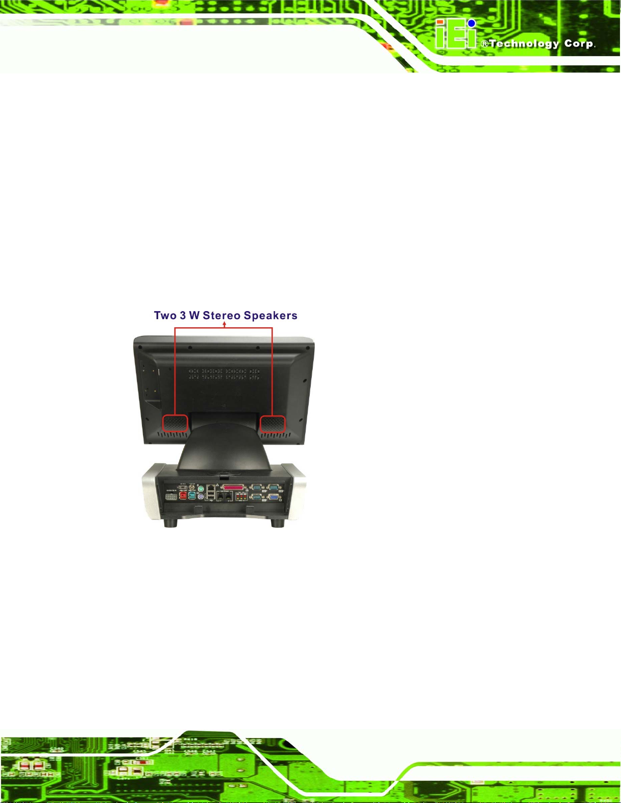
Built-in two 3 W stereo speakers
IP 64 compliant front panel
AT or ATX power mode
Second displays support
Touch screen
Fanless design
RoHS comlpliance
The variation of the two models is the LCD screen. The model numbers and variation are
listed below.
EP-265-910 15.0” LCD
EP-267-910 17.0” LCD
1.1.2 Applications
The EP-265-910/EP-267-910 POS system is elegant yet sophisticated systems that are
easily implemented in diverse Point-of-Sales (POS) environments.
Page 3
Page 18

1.2 External Overview
1.2.1 General Description
The stylish EP-265-910/EP-267-910 POS system comprises of a monitor and an
aluminum chassis. The monitor is surrounded by an ABS/PC plastic hard cover and can
be tilted to adjust the viewing angle. The monitor also contains two 3 W stereo speakers
inside the monitor rear panel. The aluminum chassis consists of rear panel, bottom panel
and two side panels (left and right). The I/O interface panel located on the rear panel of
the EP-265-910/EP-267-910 chassis provides access to external interface connectors.
1.2.2 Monitor Front Panel
The front side of the EP-265-910/EP-267-910 is a flat panel TFT LCD screen surrounded
E-265-910/EP-267-910 Enrich POS System
by an ABS/PC plastic hard cover (
viewing angle (
Figure 1-3).
Figure 1-2). The front panel can be tilted to adjust the
Figure 1-2: EP-265-910/EP-267-910 Monitor Front View
Page 4
Page 19

EP-265-910/EP-267-910 Enrich POS System
Figure 1-3: EP-265-910/EP-267-910 Viewing Angle Adjustment
1.2.3 Monitor Right Side Panel
The right side panel of the EP-265-910/EP-267-910 monitor has a set of buttons to control
the LCD brightness and the volume of the speakers. The monitor right side panel also
provides access to the I/O interface panel that enables connection to a wide range of
external peripheral devices (
Figure 1-4).
Figure 1-4: EP-265-910/EP-267-910 Monitor Right Side View
Page 5
Page 20

E-265-910/EP-267-910 Enrich POS System
1.2.3.1 I/O Interface Panel
The I/O interface panel located on the right side of the monitor (see Figure 1-4 above) has
the following I/O interface connectors:
1 x Serial port connector (COM1)
1 x 12 V PoweredUSB connector
2 x USB 2.0 connectors
1 x COM port power selecting switch (12 V / 5V)
The external I/O interface connectors on the rear side of the monitor are shown in
Figure
1-5.
Figure 1-5: I/O Interface Connectors on the Monitor Right Side Panel
1.2.4 I/O Interface Panel
The I/O interface panel is located on the rear side of the EP-265-910/EP-267-910 chassis
and protected by an easily-removed cover (
following I/O interface connectors:
1 x 12 V or 24 V DC In connector
1 x 12 V DC Out connector
Page 6
Figure 1-6). The I/O interface panel has the
Page 21

EP-265-910/EP-267-910 Enrich POS System
1 x AT/ATX power mode switch
1 x 12 V PoweredUSB connector
1 x 24 V PoweredUSB connector
1 x Keyboard connector
1 x Mouse connector
1 x LAN connector
2 x USB 2.0 connectors
1 x Parallel port connector
2 x RJ-12 connectors
3 x 5 V / 12 V serial port connectors (COM3, COM4 and COM5)
1 x VGA connector
The external I/O interface connectors on the rear panel are shown in Figure 1-6.
Figure 1-6: EP-265-910/EP-267-910 I/O Interface Panel
Page 7
Page 22

1.2.5 Chassis Left Side Panel
The left side panel of the chassis has a power switch to control the system ATX power
E-265-910/EP-267-910 Enrich POS System
on/off (
Figure 1-7).
Figure 1-7: EP-265-910/EP-267-910 Left Side View
1.3 Specifications
1.3.1 Preinstalled Hardware Components
The EP-265-910/EP-267-910 POS system has the following preinstalled components:
1 x Motherboard
1 x TFT LCD screen
1 x Touch screen
1 x Inverter
1 x Wireless LAN module
1 x DDR2 memory module
1 x AT/ATX switch
2 x 3 W stereo speakers
Page 8
Page 23

EP-265-910/EP-267-910 Enrich POS System
The following section lists the system specifications. The technical specifications for some
other preinstalled components are shown in the Appendix A.
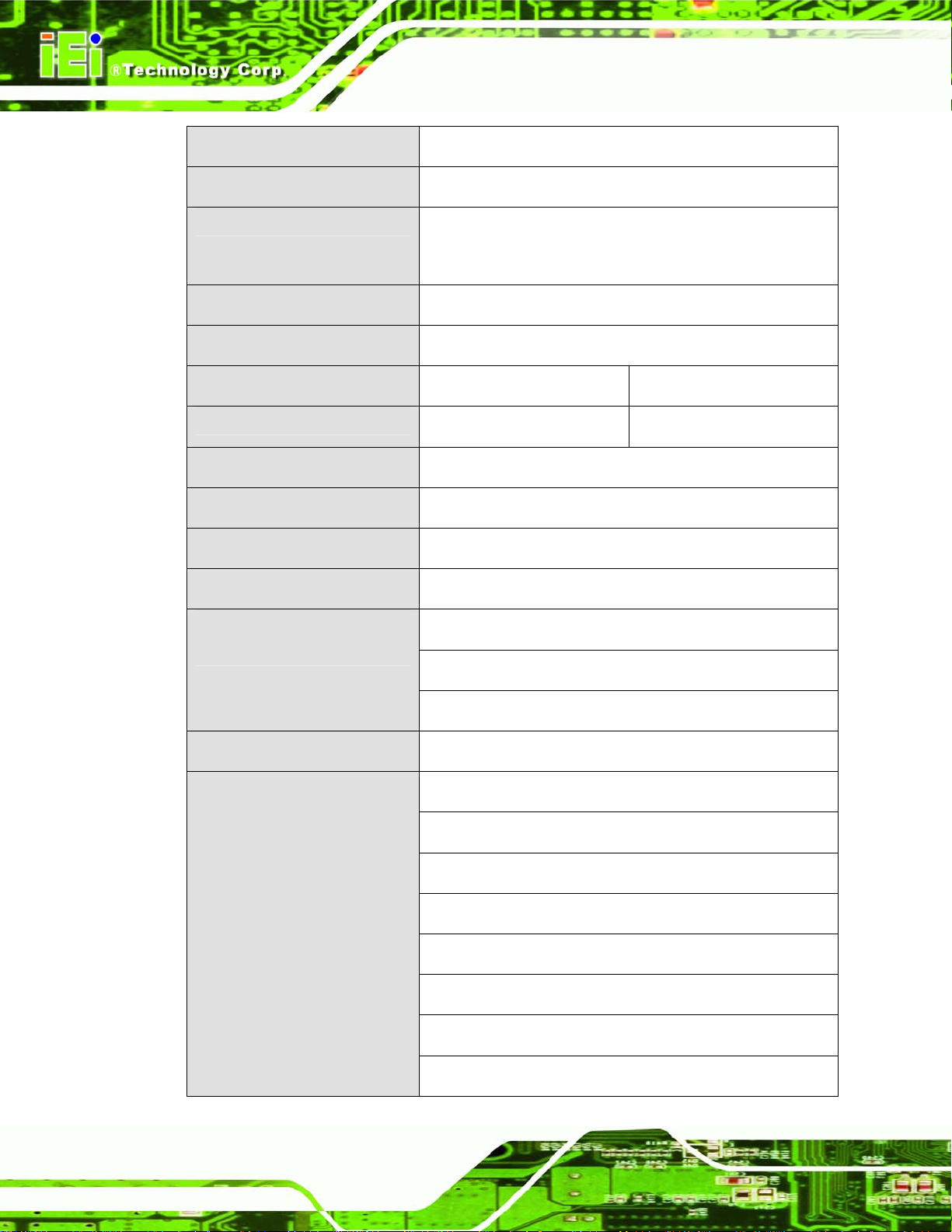
1.3.2 System Specifications
The technical specifications for the EP-265-910/EP-267-910 system are listed in
Table 1-1.
Specification
LCD Size
Max. Resolution
Brightness
Contrast Ratio
LCD Color
Pixel Pitch (mm)
Viewing Angle (H-V)
Backlight MTBF
SBC Model
CPU
Chipsets
EP-265-910 EP-267-910
15” 17”
1024 x 768 (XGA) 1280 x 1024 (SXGA)
350 cd/m2 300 cd/m2
400:1 800:1
262K 16.7M
0.297 (H) x 0.297 (V) 0.264 (H) x 0.264 (V)
120 (H) / 100 (V) 160 (H) / 160 (V)
50,000 hours 50,000 hours
EPMB-9103
1.0 GHz Intel® Celeron® M on-board
Intel® 910GMLE + ICH6M
Memory
SSD
Watchdog Timer
Audio
One 1.0 GB DDR2 SDRAM DIMM pre-installed
(Two 240-pin DIMM sockets support up to 2 GB
400/533 MHz DDR2 memory)
CF Type II
Software Programmable supports 1 sec. ~ 255 sec.
system reset
AMP 3.0 W + AMP 3.0 W (built-in stereo speakers)
Page 9
Page 24
E-265-910/EP-267-910 Enrich POS System
Expansion
HDD Drive Bay
Construction Material
Front Panel Color
Operation Temperature
Dimensions (W x H x D) (mm)
Net weight
IP level (front panel)
EMC
Safety
Touch Screen
1 x PCIe Mini interface (wireless LAN 802.11 b/g module)
2 x 2.5” SATA HDD bays
ABS + PC plastic front frame
Aluminum alloy chassis
Black
0ºC ~ 40ºC
375.00 x 392.66 x 334.64 406.00 x 414.52 x 350.47
8.30 kg 9.80 kg
IP 64
CE, EMC and FCC
UL and CB
Resistive Type 5-wire (touch controller IC is on board)
Power Adapter
(ACE-D825A-H-RS)
Power Consumption
I/O Ports and Switches
(I/O Interface Panel)
252 W
Input: 90 VAC ~ 264 VAC @ 50 Hz / 60 Hz
Output: 12 VDC at 4.0 A
66 W
1 x 12 V or 24 V DC In connector
1 x 12 V DC Out connector (at 4 A)
1 x AT/ATX power mode switch
1 x 24 V PoweredUSB connector (at 3 A)
1 x 12 V PoweredUSB connector (at 3A)
1 x Keyboard connector
1 x Mouse connector
Page 10
1 x LAN connector
Page 25

EP-265-910/EP-267-910 Enrich POS System
I/O Ports and Switches
(Monitor Rear Panel)
Table 1-1: EP-265-910/EP-267-910 System Specifications
2 x USB 2.0 connectors
1 x Parallel port connector
2 x RJ-12 connectors
3 x 5 V / 12 V serial port connectors
(COM3, COM4 and COM5)
1 x VGA connector
1 x Serial port connector (COM1)
1 x 12 V PoweredUSB connector
2 x USB 2.0 connectors
1 x COM1 power selecting switch
Page 11
Page 26

E-265-910/EP-267-910 Enrich POS System
Chapter
2
2 Detailed Specifications
Page 12
Page 27

EP-265-910/EP-267-910 Enrich POS System
2.1 Dimensions
The following sections provide detailed schematics and information on the dimensions of
the EP-265-910/EP-267-910.
2.1.1 EP-265-910 Dimensions
The dimensions of the EP-265-910 are shown in Figure 2-1 and listed below.
Width: 375.00 mm
Height: 392.66 mm
Depth: 334.64 mm
Figure 2-1: EP-265-910 Dimensions (mm)
Page 13
Page 28

2.1.2 EP-267-910 Dimensions
The dimensions of the EP-267-910 are shown in Figure 2-1 and listed below.
Width: 406.00 mm
Height: 414.52 mm
Depth: 350.47 mm
E-265-910/EP-267-910 Enrich POS System
Figure 2-2: EP-267-910 Dimensions (mm)
2.2 Intel® Celeron® M Processor Support
A 373 Intel® Celeron® M processor is installed in the system. The processor has a CPU
speed of 1.0 GHz and a 400 MHz front side bus (FSB). The processor also comes with a
512 KB L2 cache. The processor is protected by the dust-proof heat sink shown in
2-3 below.
Page 14
Figure
Page 29

EP-265-910/EP-267-910 Enrich POS System
Figure 2-3: CPU and Chipsets Heat Sink
Intel® Celeron® M processor supports the following Intel® features:
90 nanometer process technology
Supports Intel Architecture with Dynamic Execution
Data Prefetch Logic
On-die 512 KB second level cache
Streaming SIMD extensions 2 (SSE2)
2.3 Motherboard Components
The following sections describe some of the features on the motherboard.
2.3.1 Memory Support
2.3.1.1 Installed Memory
One 240-pin 1.0 GB DDR2 SDRAM DIMM is installed in the EP-265-910/EP-267-910 and
controlled by the Intel® 910GMLE GMCH installed on the internal motherboard.
2.3.1.2 Additional Memory
The Intel® 910GMLE is capable of supporting two 240-pin 1.0 GB (max.) 533 MHz or
400 MHz DDR2 SDRAM DIMM (system max. 2.0 GB). If additional memory is required,
please contact an IEI sales representative and discuss the necessary system
requirement.
Page 15
Page 30

Figure 2-4: Memory Module and Memory Socket
2.3.2 Storage Capacity
E-265-910/EP-267-910 Enrich POS System
The EP-265-910/EP-267-910 comes with two hard disk drive bays for two 2.5” SATA
HDDs (
panels.
Figure 2-5). The hard disk drive bay can be access by removing the bottom
Figure 2-5: SATA Hard Disk Drive Bays
Page 16
The system can also support a CompactFlash® Type II (CF Type II) memory disk
Figure 2-6).
(
Page 31

EP-265-910/EP-267-910 Enrich POS System
Figure 2-6: CompactFlash® Slot
2.4 External Peripheral Interface Connectors
The following section describes the external peripheral interface connectors on the real
panel and the bottom panel of the POS system.
2.4.1 Serial Port Connectors
The EP-265-910/EP-267-910 has four serial ports, one on the monitor rear panel (COM1)
and three on the I/O interface panel (COM3, COM4 and COM5). Pin 9 on these four serial
port DB-9 connectors can be set as either +5 V or +12 V. Pin 9 settings are shown with
yellow or red LED indicators next to the DB-9 CON port connectors. Enabling COM
devices to be powered through the COM port eliminates unnecessary and messy cabling.
Page 17
Page 32

E-265-910/EP-267-910 Enrich POS System
Figure 2-7: COM Ports and LED Indicators
Two of the serial ports (COM1 and COM2) are interfaced to the ITE IT8712 super I/O,
through the low pin count (LPC) bus to the ICH6M Southbridge. The remaining four serial
ports (COM3, COM4 and COM5) are connected to the ICH6M LPC bus through a Fintek
serial port controller.
2.4.2 LAN Connectivity
One of the PCI Express (PCIe x1) lanes from the ICH6M Southbridge is interfaced to a
Broadcom BCM5787 PCIe gigabit Ethernet (GbE) controller. The BCM5787 is then
connected directly to the RJ-45 connector on the rear panel and provides external PCIe
GbE connectivity.
Page 18
Page 33

EP-265-910/EP-267-910 Enrich POS System
Figure 2-8: RJ-45 Ethernet Connector
The Broadcom BCM5787M PCIe GbE controller is a 10/100/1000BASE-T Ethernet LAN
controller. The BCM5787M combines a triple-speed IEEE 802.3 compliant Media Access
Controller (MAC) with a triple-speed Ethernet transceiver, a PCIe bus interface, and an
on-chip buffer memory. Some of the BCM5787 controller features are listed below:
Integrated 10/100/1000BASE-T transceiver
Automatic MDI crossover function
PCIe v1.0a
10/100/1000BASE-T full/half-duplex MAC
Wake on LAN support meeting the ACPI requirements
Statistics for SNMP MIB II, Ethernet-like MIB, and Ethernet MIB (802.3z,
clause 30)
Serial EEPROM or serial flash support
2.4.3 External USB Connectors
2.4.3.1 Standard USB Connectors
The EP-265-910/EP-267-910 has four USB 2.0 connectors, two on the monitor rear panel
and two on the chassis rear panel. All of the USB 2.0 connectors are interfaced directly to
the USB controllers on the ICH6M Southbridge. The USB connectors are fully compliant
Page 19
Page 34

with USB specification Revision 2.0 and USB specification Revision 1.1 and can be
interfaced to both USB 1.1 and USB 2.0 compliant devices.
E-265-910/EP-267-910 Enrich POS System
Figure 2-9: External Standard USB Ports
2.4.3.2 PoweredUSB Connectors
The EP-265-910/EP-267-910 has three PoweredUSB connectors, one on the monitor rear
panel and two on the chassis rear panel. Two of these PoweredUSB connectors provide
+12 V power to the peripheral devices. The remaining one PoweredUSB provides +24 V
power for higher-power devices.
Figure 2-10: PoweredUSB Ports
Page 20
Page 35

EP-265-910/EP-267-910 Enrich POS System
2.4.4 Keyboard and Mouse Connectivity
Two PS/2 keyboard and mouse connectors on the chassis rear panel interface to an ITE
IT8712F super I/O chipset on the motherboard that connects through the LPC bus to the
Southbridge chipset.
Figure 2-11: Keyboard and Mouse Connectors
2.5 EP-265-910/EP-267-910 Front Side
2.5.1 Monitor
A 15” or 17” LCD screen is installed in the monitor of the EP POS system. The viewing
angle of the IP 64 compliant front panel is adjustable. The screen is shown in
below.
Figure 2-12
Figure 2-12: LCD Screen
Page 21
Page 36

E-265-910/EP-267-910 Enrich POS System
2.5.2 Touch-Screen Module
A controller for the 5-wire resistive touch screen is connected to the motherboard through
the RS-232 interface (COM 2). The sensitive touch screen is accurate, reliable and
durable. A capacitive touch screen can be integrated into the EP series instead of the
resistive touch screen. The capacitive touch screen is one of the OEM options for the EP
series.
2.6 Graphics
2.6.1 Intel® 910GMLE Integrated Graphics Media Accelerator 900
The Intel® 910GMLE has the Intel® GMA 900 integrated into the chipset and interfaced to
the VGA connector on the chassis rear panel. The Intel® GMA 900 is a 333 MHz 256-bit
graphics core and supports up to 8.5 GB/s memory bandwidth.
Figure 2-13: VGA Connector
2.6.2 Dual-Display
The system supports dual display capabilities. The second display device can be
connected to the EP-265-910/EP-267-910 through the VGA connector described above.
The supported device include
Page 22
iSignager LCD series
AFOLUX monitors
Vacuum fluorescent display (VFD)
Page 37
EP-265-910/EP-267-910 Enrich POS System
2.7 Audio
2.7.1 High Definition Audio Controller
The Integrated audio controller on the Intel® ICH6M Southbridge is integrated to a
RealTek ALC262 audio codec. The RealTek ALC262 is a four-channel High Definition
Audio codec with two 24-bit stereo DACs and three 20-bit stereo ADCs.
2.7.2 Stereo Speakers
The EP-265-910/EP-267-910 has two built-in 3 W stereo speakers on the rear of the
monitor (
Figure 2-14: Stereo Speakers
Figure 2-14).
2.8 System Power
2.8.1 Power Mode
The POS system can be run in the AT power mode or the ATX power mode. Both these
power modes are described below.
Page 23
Page 38

2.8.1.1 AT Power Mode
With the AT mode selected, the power is controlled by a central power unit rather than a
power switch. The EP-265-910/EP-267-910 POS system turns on automatically when the
power is connected. The AT mode benefits a big retail store to control multiple POS
systems from a central management center.
2.8.1.2 ATX Power Mode
With the ATX mode selected, the EP-265-910/EP-267-910 POS system goes in a standby
mode when it is turned off. The POS system can be easily turned on via network or a
power switch in standby mode. Remote power control is perfect for POS applications
since the POS system can be set individually and controlled remotely.
2.8.2 Power Supply
E-265-910/EP-267-910 Enrich POS System
The system is shipped with a 100 V to 240 V IEI AC power supply unit (PSU) that has a
maximum power output of 252 W. The PSU has additional 12 V and 24 V DC output
connectors. The power supply is also equipped with two cooling fans. The power supply is
shown in below.
Figure 2-15: Power Supply Unit
2.8.3 Power Connectors
There are two power connectors on the EP-265-910/EP-267-910 POS system located on
Page 24
the chassis rear panel. One is a 12 V or 24 V input connector and the other is a 12 V
output connector. These connectors are shown in
Figure 2-16 below.
Page 39

EP-265-910/EP-267-910 Enrich POS System
Figure 2-16: Power Connectors
2.8.3.1 Power Input Connector
A 10-pin connector on the connector interface panel is connected to the po we r supply and
can input 12 V or 24 V of direct current into the system.
2.8.3.2 Power Output Connector
A standard power inlet on the connector interface panel is provides 12 V of direct current
to an external peripheral device such as a thermal printer.
2.8.4 RJ-12 Connectors for Cash Drawer Power
Two RJ-12 connectors on the chassis rear panel interface can provide 24 V or 12 V of
power to a cash drawer. The cash drawer control can be controlled through the digital I/O
and monitored through the Intelligent System Management Module (iSMM).
Figure 2-17: RJ-12 Connectors
Page 25
Page 40

2.9 Wireless Ethernet
An integrate wireless LAN module and PIFA antenna on the EP-265-910/EP-267-910
ensures an uninterrupted wireless connection. PIFA antennas can receive high-quality,
uniform signals in any location from all directions without any signal degradation or
impedance and are the most efficient antennas on the market.
E-265-910/EP-267-910 Enrich POS System
Figure 2-18: Wireless LAN Mini PCI Card
2.10 Thermal Management
Thermal management is critical in optimizing system performance. Failure to maintain
proper temperature within the system may result in irreparable damage to the POS
system. The EP-265-910/EP-267-910 POS System is an effective heat dissipation system.
The heat sink on the main board works together with the heat pipe to dissipate the heat
from the POS system. The heat flows out the system via the front meshed cover and make
the POS system stable and reliable.
Page 26
Figure 2-19: CPU Heat Sink Air Vent
Page 41

EP-265-910/EP-267-910 Enrich POS System
Chapter
3
3 Unpacking
Page 27
Page 42

3.1 Unpacking
To unpack the flat POS system, follow the steps below:
WARNING!
The front side LCD screen has a protective plastic cover stuck to the
screen. Only remove the plastic cover after the POS system has been
properly installed. This ensures the screen is protected during the
installation process.
Step 1: Use box cutters, a knife or a sharp pair of scissors that seals the top side of the
external (second) box.
E-265-910/EP-267-910 Enrich POS System
Step 2: Open the external (second) box.
Step 3: Use box cutters, a knife or a sharp pair of scissors that seals the top side of the
internal (first) box.
Step 4: Lift the monitor out of the boxes.
Step 5: Remove both polystyrene ends, one from each side.
Step 6: Pull the plastic cover off the POS system.
Step 7: Make sure all the components listed in the packing list are present. Step 0:
Page 28
Page 43

EP-265-910/EP-267-910 Enrich POS System
3.1.1 Packing List
The EP-265-910/EP-267-910 POS system is shipped with the following components:
Quantity Item Image
1 EP-265-910/EP-267-910 POS system
1 Screw set
1 Power supply
1 Power cord
1 Touch pen
1 User manual CD and driver CD
If any of these items are missing or damaged, contact the distributor or sales
representative immediately.
Page 29
Page 44

E-265-910/EP-267-910 Enrich POS System
Chapter
4
4 Installation
Page 30
Page 45

EP-265-910/EP-267-910 Enrich POS System
4.1 Anti-static Precautions
WARNING:
Failure to take ESD precautions during the maintenance of the EP
series may result in permanent damage to the EP series and severe
injury to the user.
Electrostatic discharge (ESD) can cause serious damage to electronic components,
including the EP-265-910/EP-267-910. Dry climates are especially susceptible to ESD. It
is therefore critical that whenever the EP-265-910/EP-267-910 is accessed internally, or
any other electrical component is handled, the following anti-static precautions are strictly
adhered to.
Wear an anti-static wristband: - Wearing a simple anti-static wristband can
help to prevent ESD from damaging the board.
Self-grounding: - Before handling the board touch any grounded conducting
material. During the time the board is handled, frequently touch any
conducting materials that are connected to the ground.
Use an anti-static pad: - When configuring the EP-265-910/EP-267-910,
place it on an antic-static pad. This reduces the possibility of ESD damaging
the EP-265-910/EP-267-910.
Only handle the edges of the PCB: - When handling the PCB, hold the PCB
by the edges.
4.2 Installation Precautions
When installing the POS system, please follow the precautions listed below:
Power turned off: When installing the POS system, make sure the power is
off. Failing to turn off the power may cause severe injury to the body and/or
damage to the system.
Certified Engineers: Only certified engineers should install and modify
onboard functionalities.
Page 31
Page 46

Anti-static Discharge: If a user open the rear panel of the POS system, to
E-265-910/EP-267-910 Enrich POS System
configure the jumpers or plug in added peripheral devices, ground themselves
first and wear and anti-static wristband.
4.3 Preinstalled Components
The following components are all preinstalled.
Motherboard
TFT LCD screen
1.0 GB DDR2 memory module
Resistive type touch screen
Wireless LAN module
AT/ATX power switch
3 W stereo speakers
Preinstalled OEM customizations may include the following.
Different DDR2 memory module
Hard disk drive
CF card
Component installation is described in the following sections.
4.4 Installation and Configuration Steps
The following installation steps must be followed.
Step 1: Unpack the POS system
Step 2: Install CF card
Step 3: Install HDD
Step 4: Configure the system
Page 32
Step 5: Mount a second display (optional)
Step 6: Connect peripheral devices to the I/O interface panel of the POS system.
Page 47

EP-265-910/EP-267-910 Enrich POS System
Step 0:
4.5 Remove the Bottom Panels
To access the CF slot and HDD slot, the bottom panels must be removed. To remove the
bottom panels, please follow the steps below.
Step 1: Adjust the monitor (
the monitor front panel on the table.
Figure 4-1: Monitor Adjustment
Figure 4-1) and turn the EP-265-910/EP-267-910 over to put
Step 2: Remove the bottom panels. Remove the five retention screws (
from the bottom panel and lift the two bottom panels off the
EP-265-910/EP-267-910. Step 0:
Figure 4-2)
Page 33
Page 48

E-265-910/EP-267-910 Enrich POS System
Figure 4-2: Bottom Panel Retention Screws
4.6 CF Card Installation
The EP series has one CF Type II slot. To install the CF card, follow the instructions
below.
Step 1: Remove the bottom panels. Refer to Section
Step 2: Install the CF Card. Locate the CF card socket in the chassis. Correctly align
the CF card with the socket and insert the CF card into the socket.
Figure 4-3.
See
4.5.
Page 34
Page 49

EP-265-910/EP-267-910 Enrich POS System
Figure 4-3: CF Card Installation
Step 3: Reinstall the bottom panels. Make sure the bottom panels are properly
secured with the previously removed retention screws.Step 0:
4.7 HDD Installation
The EP series has two HDD slots inside the bottom panel for two 2.5” SATA HDDs. To
install the HDD, follow the instructions below.
Step 1: Remove the bottom panels. Refer to Section
Step 2: Locate the HDD slot in the EP series.
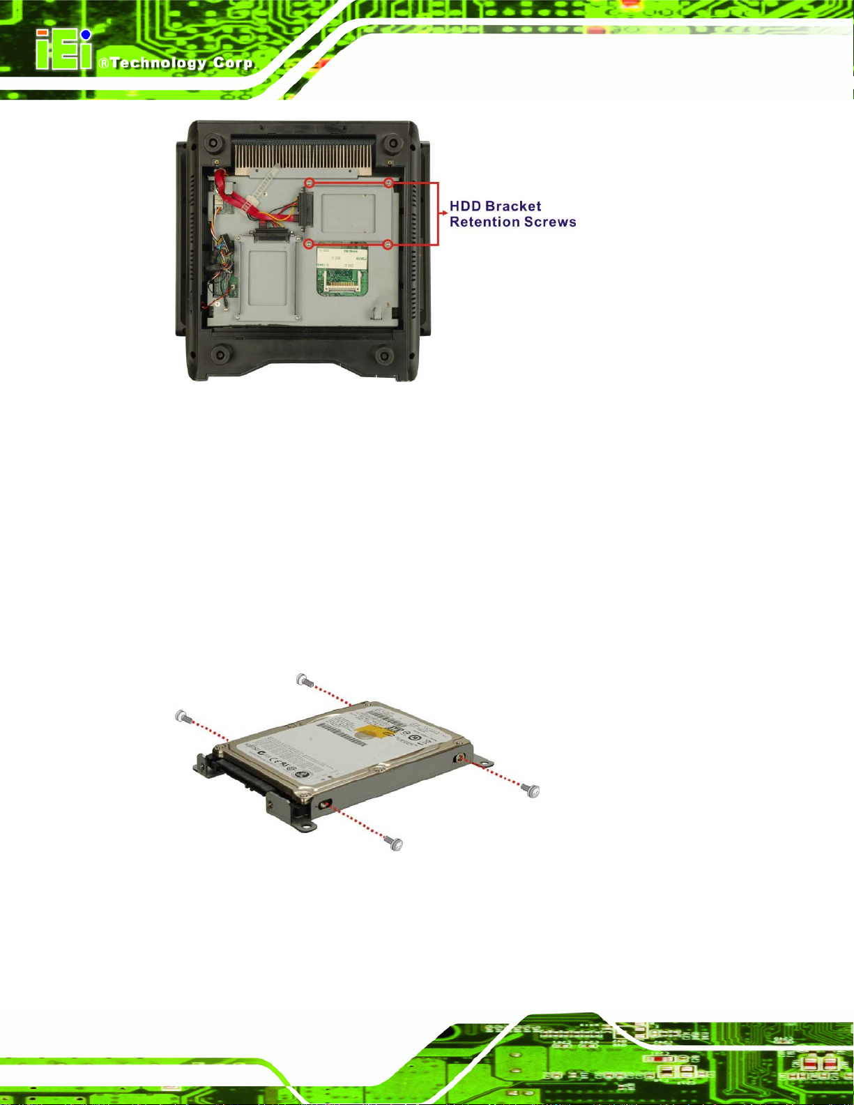
Step 3: Remove the HDD bracket. The HDD bracket is secured to the aluminum
chassis by four retention screws (
please remove the four retention screws.
4.5.
Figure 4-4). To remove the HDD bracket,
Page 35
Page 50
E-265-910/EP-267-910 Enrich POS System
Figure 4-4: HDD Bracket Retention Screws
Step 4: Place one 2.5” SATA HDD onto the HDD bracket as shown in Figure 4-5.
Connect the HDD to the SATA cable connector.
Step 5: Secure the HDD. Align the four retention screw holes on the both side of the
HDD with the retention screw holes of the HDD bracket. Insert four retention
screws into the both sides of the HDD bracket to secure the HDD to the HDD
bracket. See
Figure 4-5.
Figure 4-5: Secure the HDD with the HDD Bracket
Page 36
Step 6: Install the HDD. Correctly align the four retention screw holes on the HDD
bracket with the retention screw holes on the aluminum chassis. Insert four
Page 51

EP-265-910/EP-267-910 Enrich POS System
previously removed retention screws to secure the HDD bracket to the chassis.
Figure 4-6.
See
Figure 4-6: HDD Installation
Step 7: Reinstall the bottom panels. Make sure the bottom panels are properly
secured with the previously removed retention screws.Step 0:
4.8 Jumper Settings
NOTE:
A jumper is a metal bridge used to close an
electrical circuit. It consists of two or three metal
pins and a small metal clip (often protected by a
plastic cover) that slides over the pins to connect
them. To CLOSE/SHORT a jumper means
connecting the pins of the jumper with the plastic
clip and to OPEN a jumper means removing the
plastic clip from a jumper.
Figure 4-7: Jumper Locations
The following jumpers can be found on the motherboard installed in the EP series. Before
the EP series is installed, the jumpers must be set in accordance with the desired
Page 37
Page 52

configuration. The jumpers on the EP-265-910/EP-267-910 motherboard are listed in
Table 4-1.
Description Label Type
Cash drawer 1 voltage select JP11 3-pin header
Cash drawer 2 voltage select JP12 3-pin header
CF voltage select JP6 3-pin header
Clear CMOS JP3 2-pin header
COM3 Pin 9 setting JP8 3-pin header
COM4 Pin 9 setting JP9 3-pin header
COM5 Pin 9 setting JP10 3-pin header
E-265-910/EP-267-910 Enrich POS System
Table 4-1: Jumpers
4.8.1 Access the Jumpers
To access the jumpers, please follow the steps below.
Step 1: Adjust the monitor and turn the EP-265-910/EP-267-910 over to put the monitor
front panel on the table.
Step 2: Remove the bottom panels. Remove the five retention screws (
from the bottom panel and lift the two bottom panels off the
EP-265-910/EP-267-910.
Figure 4-9)
Page 38
Page 53

EP-265-910/EP-267-910 Enrich POS System
Figure 4-8: Bottom Panel Retention Screws
Step 3: Remove the aluminum chassis. The motherboard is installed inside the
aluminum chassis. To access the motherboard, remove the four retention
screws and gently lift the aluminum chassis off the EP-265-910/EP-267-910.
Step 0:
Figure 4-9: Motherboard Chassis Retention Screws
Page 39
Page 54

4.8.2 Preconfigured Jumpers
WARNING:
Do not change the settings on the jumpers in described here. Doing so
may disable or damage the system
The following jumpers are preconfigured for the EP-265-910/EP-267-910. Users should
NOT change these jumpers.
Jumper Name Label Type
FSB speed setup JP7 2-pin header
LVDS voltage selection JP4 3-pin header
E-265-910/EP-267-910 Enrich POS System
Panel Type and Resolution JP1 8-pin header
Table 4-2: Preconfigured Jumpers
4.8.3 Cash Drawer Voltage Select
Jumper Label: JP11 and JP12
Jumper Type:
Jumper Settings: See
Jumper Location: See
Two jumpers (JP11 and JP12) configure pin 4 on RJ-12 cash drawer connectors (CN8
and CN9). Pin 4 on the RJ-12 cash drawer connectors can be set as either +12 V or +24 V.
The Cash Drawer Voltage Select jumper selection options are shown in
3-pin header
Table 4-3
Figure 4-10
Table 4-3.
Page 40
Page 55

EP-265-910/EP-267-910 Enrich POS System
Short 1 – 2 (Default) Short 2 – 3
JP11 Cash drawer 1 (CN1) use +12 V
JP12 Cash drawer 2 (CN2) use +12 V
Cash drawer 1 (CN1) use +24 V
Cash drawer 2 (CN2) use +24 V
Table 4-3: Cash Drawer Voltage Select Jumper Settings
The Cash Drawer Voltage Select jumper locations are shown in Figure 4-10 below.
Figure 4-10: Cash Drawer Voltage Select Jumper Locations
4.8.4 CF Voltage Select
Jumper Label: JP6
Jumper Type:
Jumper Settings: See
Jumper Location: See
The CF Voltage Select jumper sets the CF Type II slot can be set as either +5 V or +3.3 V.
CF Voltage Select jumper settings are shown in
3-pin header
Table 4-4
Figure 4-11
Table 4-4.
Page 41
Page 56

CF Voltage Select Description
Short 1-2 +5 V Default
Short 2-3 +3.3 V
Table 4-4: CF Voltage Select Jumper Settings
The CF Voltage Select jumper location is shown in Figure 4-11.
E-265-910/EP-267-910 Enrich POS System
Figure 4-11: CF Voltage Select Jumper Location
4.8.5 Clear CMOS Jumper
Jumper Label: JP3
Jumper Type:
Jumper Settings: See
Jumper Location: See
If the EP-265-910/EP-267-910 fails to boot due to improper BIOS settings, the clear
CMOS jumper clears the CMOS data and resets the system BIOS information. To do this,
use the jumper cap to close the pins for a few seconds then remove the jumper clip.
2-pin header
Table 4-5
Figure 4-12
Page 42
Page 57

EP-265-910/EP-267-910 Enrich POS System
If the “CMOS Settings Wrong” message is displayed during the boot up process, the fault
may be corrected by pressing the F1 to enter the CMOS Setup menu. Do one of the
following:
Enter the correct CMOS setting
Load Optimal Defaults
Load Failsafe Defaults.
After having done one of the above, save the changes and exit the CMOS Setup menu.
The clear CMOS jumper settings are shown in
Clear CMOS Description
OPEN Keep CMOS Setup Default
SHORT Clear CMOS Setup
Table 4-5: Clear CMOS Jumper Settings
The location of the clear CMOS jumper is shown in Figure 4-12 below.
Table 4-5.
Figure 4-12: Clear CMOS Jumper
Page 43
Page 58

E-265-910/EP-267-910 Enrich POS System
4.8.6 COM3, COM4 and COM5 Pin 9 Select
Jumper Label: JP8, JP9 and JP10
Jumper Type:
Jumper Settings: See
Jumper Location: See
3-pin header
Table 4-6
Figure 4-13
Three jumpers (JP8, JP9 and JP10) configure pin 9 on COM3, COM4 and COM5 DB-9
connectors. Pin 9 on the COM3, COM4 and the COM5 DB-9 connectors can be set as
either +5 V or +12 V. The COM3, COM4 and COM5 Pin 9 Setting jumper selection options
are shown in
Short 1 – 2 (Default) Short 2 – 3
JP8 COM3 Pin 9 use +5 V COM3 Pin 9 use +12 V
JP9 COM4 Pin 9 use +5 V COM4 Pin 9 use +12 V
JP10 COM5 Pin 9 use +5 V COM5 Pin 9 use +12 V
Table 4-6.
Table 4-6: COM2, COM3 and COM5 Pin 9 Setting Jumper Settings
Page 44
The COM3, COM4 and COM5 Pin 9 Setting jumper location are shown in Figure 4-13
below.
Figure 4-13: COM3, COM4 and COM5 Pin 9 Setting Jumper Locations
Page 59

EP-265-910/EP-267-910 Enrich POS System
4.9 Mounting the Second Display (Optional)
To mount a second display onto the EP-265-910/EP-267-910, please follow the steps
below.
Step 1: Remove the I/O interface cover on the chassis rear panel of the
EP-265-910/EP-267-910 (
Figure 4-14).
Figure 4-14: I/O Interface Cover Removal
Step 2: Remove the mounting hole cover on the chassis from the rear of the
EP-265-910/EP-267-910 (
Figure 4-15).
Figure 4-15: Mounting Hole Cover Removal
Page 45
Page 60

E-265-910/EP-267-910 Enrich POS System
Step 3: Align the thee retention screw holes on the second display device with the
retention screw holes on the mounting hole. Insert the three retention screws to
secure the second display to the EP-265-910/EP-267-910(
Figure 4-16: Second Display Installation
Figure 4-16).
Page 46
Step 4: Organize the second display cables and connect the connector to the
connectors on the I/O interface panel (
Figure 4-17).
Figure 4-17: Organized Second Display Cables
Page 61

EP-265-910/EP-267-910 Enrich POS System
Step 5: Replace the I/O interface cover. Step 0:
4.10 Bottom Panel Switch and Connectors
4.10.1 AT/ATX Mode Selection
AT and ATX power modes can both be used on the EP series POS system. The selection
is made through an AT/ATX switch on the chassis rear panel (
mode or ATX mode, follow the steps below.
Step 1: Locate the AT/ATX switch on the chassis rear panel (
Figure 4-18). To select AT
Figure 4-18).
Figure 4-18: AT/ATX Switch
Step 2: Adjust the AT/ATX switch. The default mode is ATX mode (
Figure 4-18).Step 0:
4.10.2 LAN Connection
There is one external RJ-45 LAN connector. The RJ-45 connector enables connection to
an external network. To connect a LAN cable with an RJ-45 connector, please follow the
instructions below.
Step 1: Locate the RJ-45 connectors on the I/O interface panel of the
EP-265-910/EP-267-910 series.
Step 2: Align the connectors. Align the RJ-45 connector on the LAN cable with one of
the RJ-45 connectors on the I/O interface panel of the EP-265-910/EP-267-910
series. See
Figure 4-19.
Page 47
Page 62

E-265-910/EP-267-910 Enrich POS System
Figure 4-19: LAN Connection
Step 3: Insert the LAN cable RJ-45 connector. Once aligned, gently insert the LAN
cable RJ-45 connector into the RJ-45 connector. Step 0:
4.10.3 Serial Device Connection
The EP-265-910/EP-267-910 series has four male DB-9 connectors for serial devices to
be connected. Follow the steps below to connect a serial device to the
EP-265-910/EP-267-910 series POS system.
Step 1: Locate the DB-9 connector. The location of the DB-9 connector is shown in
Chapter 2.
Step 2: Insert the serial connector. Insert the DB-9 connector of a serial device into
the DB-9 connector on the I/O interface panel. See
Figure 4-20.
Page 48
Page 63

EP-265-910/EP-267-910 Enrich POS System
Figure 4-20: Serial Device Connector
Step 3: Secure the connector. Secure the serial device connector to the external
interface by tightening the two retention screws on either side of the connector.
4.10.4 USB Device Connection
There are four external USB 2.0 connectors. All connectors are perpendicular to the
EP-265-910/EP-267-910 series. To connect a USB 2.0 or USB 1.1 device, please follow
the instructions below.
Step 1: Located the USB connectors. The locations of the USB connectors are shown
in Chapter 2.
Step 2: Align the connectors. Align the USB device connector with one of the
connectors on the I/O interface panel. See
Figure 4-21.
Step 0:
Page 49
Page 64

E-265-910/EP-267-910 Enrich POS System
Figure 4-21: USB Device Connection
Step 3: Insert the device connector. Once aligned, gently insert the USB device
connector into the onboard connector. Step 0:
4.10.5 Parallel Device Connection
The EP-265-910/EP-267-910 has a single female DB-25 connector on the chassis rear
panel for parallel devices. Follow the steps below to connect a parallel device to the
EP-265-910/EP-267-910.
Step 1: Locate the DB-25 connector. The location of the DB-25 connector is shown in
Chapter 3.
Step 2: Insert the DB-25 connector. Insert the DB-25 connector of a parallel device
into the DB-25 connector on the external peripheral interface. See
Figure 4-22.
Page 50
Page 65

EP-265-910/EP-267-910 Enrich POS System
Figure 4-22: Parallel Device Connector
Step 3: Secure the connector. Secure the DB-25 connector to the external interface by
tightening the two retention screws on either side of the connector. Step 0:
Page 51
Page 66

E-265-910/EP-267-910 Enrich POS System
Chapter
4
5 System Maintenance
Page 52
Page 67

EP-265-910/EP-267-910 Enrich POS System
5.1 System Maintenance Introduction
If the components of the EP-265-910/EP-267-910 series fail they must be replaced.
Components that can be replaced include:
CF module
SATA HDD
Wireless LAN module
DIMM module
Please contact the system reseller or vendor to purchase the replacement parts. Back
cover removal instructions and component replacement for the EP-265-910/EP-267-910
series are described below.
5.2 Anti-static Precautions
WARNING:
Failure to take ESD precautions during the maintenance of the
EP-265-910/EP-267-910 may result in permanent damage to the
EP-265-910/EP-267-910 and severe injury to the user.
Electrostatic discharge (ESD) can cause serious damage to electronic components,
including the EP series. Dry climates are especially susceptible to ESD. It is therefore
critical that whenever the EP series is accessed internally, or any other electrical
component is handled, the following anti-static precautions are strictly adhered to.
Wear an anti-static wristband: - Wearing a simple anti-static wristband can
help to prevent ESD from damaging the board.
Self-grounding:- Before handling the board touch any grounded conducting
material. During the time the board is handled, frequently touch any
conducting materials that are connected to the ground.
Use an anti-static pad: When configuring the EP series, place it on an
antic-static pad. This reduces the possibility of ESD damaging the EP series.
Page 53
Page 68

Only handle the edges of the PCB:- When handling the PCB, hold the PCB
by the edges.
5.3 Turn off the Power
WARNING:
Failing to turn off the system before opening it can cause permanent
damage to the system and serious or fatal injury to the user.
Before any maintenance procedures are carried out on the system, make sure the system
is turned off.
E-265-910/EP-267-910 Enrich POS System
5.4 Replacing Components
5.4.1 Hard Disk Drive Replacement
If the HDD fails, please follow the steps below:
Step 1: Follow all anti-static procedures. See Section
Step 2: Turn off the power. See Section
Step 3: Follow the steps described in Section
5.4.2 CF Card Replacement
The EP-265-910/EP-267-910 has one CF Type II slot. To replace the CF card, follow the
instructions below.
Step 1: Follow all anti-static procedures. See Section
5.2.
5.3.
4.7 to replace the HDD. Step 0:
5.2.
Page 54
Step 2: Turn off the power. See Section
Step 3: Follow the steps described in Section
5.3.
4.6 to replace the CF card. Step 0:
Page 69

EP-265-910/EP-267-910 Enrich POS System
5.4.3 DIMM Module Replacement
WARNING:
Using incorrectly specified DIMM may cause permanently damage the
EP-265-910/EP-267-910. Please make sure the purchased DIMM
complies with the memory specifications of the
EP-265-910/EP-267-910.
To replace the DIMM module, please follow the steps below.
Step 1: Follow all anti-static procedures. See Section
Step 2: Turn off the power. See Section
Step 3: Remove the internal aluminum chassis. See Section
Step 4: Locate the DIMM module. The DIMM module is located below the CPU heat
sink. See
Figure 5-1.
5.3.
5.2.
4.8.1.
Figure 5-1: DIMM Socket Location
Step 5: Open the DIMM socket handles. The DIMM socket has two handles that
secure the DIMM into the socket. Before the DIMM can be removed from the
socket, the handles must be opened.
Page 55
Page 70

Step 6: Open the DIMM socket handles. The DIMM socket has two handles that
secure the DIMM into the socket. Before the DIMM can be inserted into the
E-265-910/EP-267-910 Enrich POS System
socket, the handles must be opened. See
Figure 5-2.
Figure 5-2: Installing a DIMM
Step 7: Align the DIMM with the socket. The DIMM must be oriented in such a way
that the notch in the middle of the DIMM must be aligned with the plastic bridge
in the socket. See
Step 8: Insert the DIMM. Once properly aligned, the DIMM can be inserted into the
socket. As the DIMM is inserted, the white handles on the side of the socket will
close automatically and secure the DIMM to the socket. See
Figure 5-2.
Figure 5-2.Step 0:
5.4.4 Wireless Module Replacement
To replace the wireless module, please follow the steps below.
Step 1: Follow all anti-static procedures. See Section
Step 2: Turn off the power. See Section
Step 3: Remove the internal aluminum chassis. See Section
5.3.
5.2.
4.8.1.
Page 56
Page 71

EP-265-910/EP-267-910 Enrich POS System
Step 4: Locate the wireless module. The wireless module is located below the DIMM
sockets. See
Figure 5-3.
Figure 5-3: Wireless Module Location
Step 5: Open the Mini PCIe socket arm clips. The Mini PCIe socket has two clips that
secure the Mini PCIe wireless module into the socket. Before the wireless
module can be removed from the socket, the clips must be opened.
Step 6: Remove the wireless module. Once the two clips of the Mini PCIe socket are
open, remove the wireless module from the socket.
Step 7: Align the new wireless module with the Mini PCIe socket. The wireless
module must be oriented in such a way that the notch in the wireless module
must be aligned with the plastic bridge in the socket.
Step 8: Insert the wireless module. Push the wireless module into the socket at an
angle.
Step 9: Secure the wireless module. Push the wireless module down until the two
clips into place, securing the card in place.
5.4.5 Motherboard Replacement
A user cannot replace a motherboard. If the motherboard fails it must be shipped back to
IEI to be replaced. If the system motherboard has failed, please contact the system vendor,
reseller or an IEI sales person directly.
Page 57
Page 72

E-265-910/EP-267-910 Enrich POS System
Chapter
6
6 AMI BIOS Setup
Page 58
Page 73

EP-265-910/EP-267-910 Enrich POS System
6.1 Introduction
A licensed copy of AMI BIOS is preprogrammed into the ROM BIOS. The BIOS setup
program allows users to modify the basic system configuration. This chapter describes
how to access the BIOS setup program and the configuration options that may be
changed.
6.1.1 Starting Setup
The AMI BIOS is activated when the computer is turned on. The setup program can be
activated in one of two ways.
1. Press the D
2. Press the D
message appears on the screen. 0.
If the message disappears before the D
again.
ELETE key as soon as the system is turned on or
ELETE key when the “Press Del to enter SETUP”
ELETE key is pressed, restart the computer and try
6.1.2 Using Setup
Use the arrow keys to highlight items, press ENTER to select, use the PageUp and
PageDown keys to change entries, press F1 for help and press E
keys are shown in.
Key Function
Up arrow Move to previous item
Down arrow Move to next item
Left arrow Move to the item on the left hand side
SC to quit. Navigation
Right arrow Move to the item on the right hand side
Esc key Main Menu – Quit and not save changes into CMOS
Status Page Setup Menu and Option Page Setup Menu --
Exit current page and return to Main Menu
Page Up key Increase the numeric value or make changes
Page Dn key Decrease the numeric value or make changes
Page 59
Page 74

F1 key General help, only for Status Page Setup Menu and Option
F2 /F3 key Change color from total 16 colors. F2 to select color
F10 key Save all the CMOS changes, only for Main Menu
Table 6-1: BIOS Navigation Keys
6.1.3 Getting Help
When F1 is pressed a small help window describing the appropriate keys to use and the
E-265-910/EP-267-910 Enrich POS System
Page Setup Menu
forward.
possible selections for the highlighted item appears. To exit the Help Window press E
SC or
the F1 key again.
6.1.4 Unable to Reboot After Configuration Changes
If the computer cannot boot after changes to the system configuration is made, CMOS
defaults. Use the jumper described in Chapter 5.
6.1.5 BIOS Menu Bar
The menu bar on top of the BIOS screen has the following main items:
Main Changes the basic system configuration.
Advanced Changes the advanced system settings.
PCIPnP Changes the advanced PCI/PnP Settings
Boot Changes the system boot configuration.
Security Sets User and Supervisor Passwords.
Chipset Changes the chipset settings.
Page 60
Exit Selects exit options and loads default settings
The following sections completely describe the configuration options found in the menu
items at the top of the BIOS screen and listed above.
Page 75

EP-265-910/EP-267-910 Enrich POS System
6.2 Main
The Main BIOS menu (BIOS Menu 1) appears when the BIOS Setup program is entered.
The Main menu gives an overview of the basic system information.
BIOS Menu 1: Main
System Overview
The System Overvie w lists a brief summary of different system components. The fields in
System Overview cannot be changed. The items shown in the system overview include:
AMI BIOS: Displays auto-detected BIOS information
Processor: Displays auto-detected CPU specifications
o Version: Current BIOS version
o Build Date: Date the current BIOS version was made
o ID: Installed BIOS ID
o Type: Names the currently installed processor
o Speed: Lists the processor speed
Page 61
Page 76

E-265-910/EP-267-910 Enrich POS System
o Count: The number of CPUs on the motherboard
System Memory: Displays the auto-detected system memory.
o Size: Lists memory size
The System Overview field also has two user configurable fields:
System Time [xx:xx:xx]
Use the System Time option to set the system time. Manually enter the hours, minutes
and seconds.
System Date [xx/xx/xx]
Use the System Date option to set the system date. Manually enter the day, month and
year.
6.3 Advanced
Use the Advanced menu to configure the CPU and peripheral devices through the
following sub-menus:
WARNING:
Setting the wrong values in the sections below may cause the system
to malfunction. Make sure that the settings made are compatible with
the hardware.
CPU Configuration (see Section 6.3.1)
IDE Configuration (see Section 6.3.2)
SuperIO Configuration (see Section 6.3.3)
Hardware Health Configuration (see Section 6.3.4)
Page 62
Remote Access Configuration (see Section 6.3.5)
USB Configuration (see Section 6.3.6)
Page 77

EP-265-910/EP-267-910 Enrich POS System
BIOS Menu 2: Advanced
6.3.1 CPU Configuration
Use the CPU Configuration menu (BIOS Menu 3) to view detailed CPU specifications and
configure the CPU.
BIOS Menu 3: CPU Configuration
Page 63
Page 78

The CPU Configuration menu (BIOS Menu 3) lists the following CPU details:
Manufacturer: Lists the name of the CPU manufacturer
Brand String: Lists the brand name of the CPU being used
Frequency: Lists the CPU processing speed
FSB Speed: Lists the FSB speed
Cache L1: Lists the CPU L1 cache size
Cache L2: Lists the CPU L2 cache size
6.3.2 IDE Configuration
Use the IDE Configuration menu (BIOS Menu 4) to change and/or set the configuration
of the IDE devices installed in the system.
E-265-910/EP-267-910 Enrich POS System
Page 64
BIOS Menu 4: IDE Configuration
Page 79

EP-265-910/EP-267-910 Enrich POS System
ATA/IDE Configurations [Compatible]
Use the ATA/IDE Configurations option to configure the ATA/IDE controller.
Disabled
Compatible
Enhanced DEFAULT
Legacy IDE Channels [PATA Pri, SATA Sec]
SA TA Only
Disables the on-board ATA/IDE controller.
Configures the on-board ATA/IDE controller to be in
compatible mode. In this mode, a SATA channel will
replace one of the IDE channels. This mode supports up
to 4 storage devices.
Configures the on-board ATA/IDE controller to be in
Enhanced mode. In this mode, IDE channels and SATA
channels are separated. This mode supports up to 6
storage devices. Some legacy OS do not support this
mode.
Only the SATA drives are enabled.
PATA Pri, SATA Sec D
PATA Only
Configure SATA as [IDE]
The Configure SATA as option appears when the ATA/IDE Configurations option is set
to Enhanced. Use the Configure SATA as option to configure SATA devices as normal
IDE devices.
IDE DEFAULT
EFAULT
Only the IDE drives are enabled.
Configures SATA devices as normal IDE device.
The IDE drives are enabled on the Primary
IDE channel. The SATA drives are enabled on
the Secondary IDE channel.
Page 65
Page 80

E-265-910/EP-267-910 Enrich POS System
AHCI
IDE Master and IDE Slave
When entering setup, BIOS auto detects the presence of IDE devices. BIOS displays the
status of the auto detected IDE devices. The following IDE devices are detected and are
shown in the IDE Configuration menu:
Primary IDE Master
Primary IDE Slave
Secondary IDE Master
Secondary IDE Slave
The IDE Configuration menu (
IDE devices installed in the system. If an IDE device is detected, and one of the above
listed four BIOS configuration options are selected, the IDE configuration options shown in
Section
6.3.2.1 appear.
Configures SATA devices as AHCI device.
BIOS Menu 4) allows changes to the configurations for the
6.3.2.1 IDE Master, IDE Slave
Use the IDE Master and IDE Slave configuration menu to view both primary and
secondary IDE device details and configure the IDE devices connected to the system.
Page 66
Page 81

EP-265-910/EP-267-910 Enrich POS System
BIOS Menu 5: IDE Master and IDE Slave Configuration
Auto-Detected Drive Parameters
The “grayed-out” items in the left frame are IDE disk drive parameters automatically
detected from the firmware of the selected IDE disk drive. The drive parameters are listed
as follows:
Device: Lists the device type (e.g. hard disk, CD-ROM etc.)
Type: Indicates the type of devices a user can manually select
Vendor: Lists the device manufacturer
Size: List the storage capacity of the device.
LBA Mode: Indicates whether the LBA (Logical Block Addressing) is a
method of addressing data on a disk drive is supported or not.
Block Mode: Block mode boosts IDE drive performance by increasing the
amount of data transferred. Only 512 bytes of data can be transferred per
interrupt if block mode is not used. Block mode allows transfers of up to 64 KB
per interrupt.
PIO Mode: Indicates the PIO mode of the installed device.
Page 67
Page 82

Type [Auto]
Use the Type BIOS option select the type of device the AMIBIOS attempts to boot from
after the Power-On Self-Test (POST) is complete.
E-265-910/EP-267-910 Enrich POS System
Async DMA: Indicates the highest Asynchronous DMA Mode that is
supported.
Ultra DMA: Indicates the highest Synchronous DMA Mode that is supported.
S.M.A.R.T.: Indicates whether or not the Self-Monitoring Analysis and
Reporting Technology protocol is supported.
32Bit Data Transfer: Enables 32-bit data transfer.
Not Installed
Auto DEFAULT
CD/DVD
ARMD
BIOS is prevented from searching for an IDE disk
drive on the specified channel.
The BIOS auto detects the IDE disk drive type
attached to the specified channel. This setting should
be used if an IDE hard disk drive is attached to the
specified channel.
The CD/DVD option specifies that an IDE CD-ROM
drive is attached to the specified IDE channel. The
BIOS does not attempt to search for other types of
IDE disk drives on the specified channel.
This option specifies an ATAPI Removable Media
Device. These include, but are not limited to:
LBA/Large Mode [Auto]
Page 68
ZIP
LS-120
Page 83

EP-265-910/EP-267-910 Enrich POS System
Use the LBA/Large Mode option to disable or enable BIOS to auto detects LBA (Logical
Block Addressing). LBA is a method of addressing data on a disk drive. In LBA mode, the
maximum drive capacity is 137 GB.
Disabled
Auto DEFAULT
Block (Multi Sector Transfer) [Auto]
Use the Block (Multi Sector Transfer) to disable or enable BIOS to auto detect if the
device supports multi-sector transfers.
Disabled
Auto DEFAULT
BIOS is prevented from using the LBA mode control on
the specified channel.
BIOS auto detects the LBA mode control on the specified
channel.
BIOS is prevented from using Multi-Sector Transfer on the
specified channel. The data to and from the device occurs
one sector at a time.
BIOS auto detects Multi-Sector Transfer support on the
drive on the specified channel. If supported the data
PIO Mode [Auto]
Use the PIO Mode option to select the IDE PIO (Programmable I/O) mode program timing
cycles between the IDE drive and the programmable IDE controller. As the PIO mode
increases, the cycle time decreases.
Auto DEFAULT
0
transfer to and from the device occurs multiple sectors at
a time.
BIOS auto detects the PIO mode. Use this value if the IDE disk
drive support cannot be determined.
PIO mode 0 selected with a maximum transfer rate of 3.3MBps
Page 69
Page 84

E-265-910/EP-267-910 Enrich POS System
1
2
3
4
DMA Mode [Auto]
Use the DMA Mode BIOS selection to adjust the DMA mode options.
Auto DEFAULT
PIO mode 1 selected with a maximum transfer rate of 5.2MBps
PIO mode 2 selected with a maximum transfer rate of 8.3MBps
PIO mode 3 selected with a maximum transfer rate of 11.1MBps
PIO mode 4 selected with a maximum transfer rate of 16.6MBps
(This setting generally works with all hard disk drives
manufactured after 1999. For other disk drives, such as IDE
CD-ROM drives, check the specifications of the drive.)
BIOS auto detects the DMA mode. Use this value if the IDE
disk drive support cannot be determined.
SWDMA0
SWDMA1
SWDMA2
MWDMA0
MWDMA1
MWDMA2
Single Word DMA mode 0 selected with a maximum data
transfer rate of 2.1MBps
Single Word DMA mode 1 selected with a maximum data
transfer rate of 4.2MBps
Single Word DMA mode 2 selected with a maximum data
transfer rate of 8.3MBps
Multi Word DMA mode 0 selected with a maximum data
transfer rate of 4.2MBps
Multi Word DMA mode 1 selected with a maximum data
transfer rate of 13.3MBps
Multi Word DMA mode 2 selected with a maximum data
transfer rate of 16.6MBps
Page 70
UDMA1
Ultra DMA mode 0 selected with a maximum data transfer
Page 85

EP-265-910/EP-267-910 Enrich POS System
rate of 16.6MBps
UDMA1
UDMA2
UDMA3
UDMA4
UDMA5
Ultra DMA mode 1 selected with a maximum data transfer
rate of 25MBps
Ultra DMA mode 2 selected with a maximum data transfer
rate of 33.3MBps
Ultra DMA mode 3 selected with a maximum data transfer
rate of 44MBps (To use this mode, it is required that an
80-conductor ATA cable is used.)
Ultra DMA mode 4 selected with a maximum data transfer
rate of 66.6MBps (To use this mode, it is required that an
80-conductor ATA cable is used.)
Ultra DMA mode 5 selected with a maximum data transfer
rate of 99.9MBps (To use this mode, it is required that an
80-conductor ATA cable is used.)
S.M.A.R.T [Auto]
Use the S.M.A.R.T option to auto-detect, disable or enable Self-Monitoring Analysis and
Reporting Technology (SMART) on the drive on the specified channel. S.M.A.R.T predicts
impending drive failures. The S.M.A.R.T BIOS option enables or disables this function.
Auto DEFAULT
Disabled
Enabled
32Bit Data Transfer [Enabled]
Use the 32Bit Data Transfer BIOS option to enables or disable 32-bit data transfers.
Prevents BIOS from using the HDD SMART feature.
Allows BIOS to use the HDD SMART feature
BIOS auto detects HDD SMART support.
Page 71
Page 86

E-265-910/EP-267-910 Enrich POS System
Disabled
Enabled DEFAULT
Prevents the BIOS from using 32-bit data transfers.
Allows BIOS to use 32-bit data transfers on supported
hard disk drives.
6.3.3 Super IO Configuration
Use the Super IO Configuration menu (BIOS Menu 6) to set or change the
configurations for the parallel ports and serial ports.
BIOS Menu 6: Super IO Configuration
Serial Port1 Address [3F8/IRQ4]
Use the Serial Port1 Address option to select the Serial Port 1 base address.
Page 72
Disabled
3F8/IRQ4 DEFAULT
3E8/IRQ4
No base address is assigned to Serial Port 1
Serial Port 1 I/O port address is 3E8 and the interrupt
Serial Port 1 I/O port address is 3F8 and the interrupt
address is IRQ4
Page 87

EP-265-910/EP-267-910 Enrich POS System
address is IRQ4
2E8/IRQ3
Serial Port 1 I/O port address is 2E8 and the interrupt
address is IRQ3
Serial Port2 Address [2F8/IRQ3]
Use the Serial Port2 Address option to select the Serial Port 2 base address.
Disabled
2F8/IRQ3 D
No base address is assigned to Serial Port 2
EFAULT
Serial Port 2 I/O port address is 3F8 and the interrupt
address is IRQ3
3E8/IRQ4
Serial Port 2 I/O port address is 3E8 and the interrupt
address is IRQ4
2E8/IRQ3
Serial Port 2 I/O port address is 2E8 and the interrupt
address is IRQ3
Parallel Port Address [378]
Use the Parallel Port Address option to select the parallel port base address.
Disabled
378 D
278
3BC
EFAULT
Parallel Port I/O port address is 278
Parallel Port I/O port address is 3BC
No base address is assigned to the Parallel Port
Parallel Port I/O port address is 378
Parallel Port Mode [Normal]
Use the Parallel Port Mode option to select the mode the parallel port operates in.
Normal D
EFAULT
The normal parallel port mode is the standard mode
for parallel port operation.
Page 73
Page 88

E-265-910/EP-267-910 Enrich POS System
EPP
ECP
ECP+EPP
The parallel port operates in the enhanced parallel
port mode (EPP). The EPP mode supports
bi-directional communication between the system
and the parallel port device and the transmission
rates between the two are much faster than the
Normal mode.
The parallel port operates in the extended
capabilities port (ECP) mode. The ECP mode
supports bi-directional communication between the
system and the parallel port device and the
transmission rates between the two are much faster
than the Normal mode
The parallel port operates in the extended
Parallel Port IRQ [IRQ7]
Use the Parallel Port IRQ selection to set the parallel port interrupt address.
IRQ5
IRQ7 D
IRQ5 is assigned as the parallel port interrupt address
EFAULT
capabilities port (ECP) mode. The ECP mode
supports bi-directional communication between the
system and the parallel port device and the
transmission rates between the two are much faster
than the Normal mode
The parallel port is also be compatible with EPP
devices described above
IRQ7 is assigned as the parallel port interrupt address
Page 74
Page 89

EP-265-910/EP-267-910 Enrich POS System
Serial Port3 Address [3E8]
Use the Serial Port3 Address option to select the base addresses for serial port 3
Disabled
3E8 D
2E8
2F0
2E0
No base address is assigned to serial port 3
EFAULT
Serial port 3 I/O port address is 3E8
Serial port 3 I/O port address is 2E8
Serial port 3 I/O port address is 2F0
Serial port 3 I/O port address is 2E0
Serial Port3 IRQ [10]
Use the Serial Port3 IRQ option to select the interrupt address for serial port 3.
10 D
11
EFAULT
Serial port 3 IRQ address is 10
Serial port 3 IRQ address is 11
Serial Port4 Address [2E8]
Use the Serial Port4 IRQ option to select the interrupt address for serial port 4.
Disabled
3E8
2E8 D
2F0
2E0
Serial Port4 IRQ [10]
Use the Serial Port4 IRQ option to select the interrupt address for serial port 4.
No base address is assigned to serial port 3
Serial port 4 I/O port address is 3E8
EFAULT
Serial port 4 I/O port address is 2E8
Serial port 4 I/O port address is 2F0
Serial port 4 I/O port address is 2E0
Page 75
Page 90

E-265-910/EP-267-910 Enrich POS System
10 D
11
Serial Port5 Address [2F0]
Use the Serial Port5 IRQ option to select the interrupt address for serial port 5.
Disabled
3E8
2E8
2F0 D
2E0
Serial Port5 IRQ [10]
EFAULT
No base address is assigned to serial port 5
Serial port 5 I/O port address is 3E8
Serial port 5 I/O port address is 2E8
EFAULT
Serial port 4 IRQ address is 10
Serial port 4 IRQ address is 11
Serial port 5 I/O port address is 2F0
Serial port 5 I/O port address is 2E0
Use the Serial Port5 IRQ option to select the interrupt address for serial port 5.
10 D
11
EFAULT
Serial port 5 IRQ address is 10
Serial port 5 IRQ address is 11
6.3.4 Hardware Health Configuration
The Hardware Health Configuration menu (BIOS Menu 7) shows the operating
temperature, fan speeds and system voltages.
Page 76
Page 91

EP-265-910/EP-267-910 Enrich POS System
BIOS Menu 7: Hardware Health Configuration
FAN Mode Setting [Full On Mode]
Use the FAN Mode Setting option to configure the CPU fan or system fan.
Full On Mode D
Automatic mode
EFAULT
Fan is off when the temperature is low
Fan is on all the time
enough. Parameters must be set by the
user.
PWM Manual mode
Pulse width modulation set manually
When the FAN Mode Setting option is in the Automatic Mode, the following parameters
can be set.
Temp. Limit of OFF
Temp. Limit of Start
Fan Start PWM
Slope PWM
Page 77
Page 92

When the FAN Mode Setting option is in the PWM Manual Mode, the following
parameters can be set.
Fan PWM control
Temp. Limit of OFF [000]
WARNING:
Setting this value too high may cause the fan to stop when the CPU is
at a high temperature and therefore cause the system to be damaged.
The Temp. Limit of OFF option can only be set if the FAN Mode Setting option is set to
E-265-910/EP-267-910 Enrich POS System
Automatic Mode. Use the Temp. Limit of OFF option to select the CPU temperature at
which the cooling fan should automatically turn off. To select a value, select the Temp.
Limit of OFF option and enter a decimal number between 000 and 127. The temperature
range is specified below.
Minimum Value: 0°C
Maximum Value: 127°C
Temp. Limit of Start [020]
WARNING:
Setting this value too high may cause the fan to start only when the
CPU is at a high temperature and therefore cause the system to be
damaged.
Page 78
The Temp. Limit of Start option can only be set if the FAN Mode Setting option is set to
Automatic Mode. Use the Temp. Limit of Start option to select the CPU temperature at
which the cooling fan should automatically turn on. When the fan starts, it rotates using the
Page 93

EP-265-910/EP-267-910 Enrich POS System
starting pulse width modulation (PWM) specified in the Fan 3 Start PWM option below. To
select a value, select the CPU Temp. Limit of Start option and enter a decimal number
between 000 and 127. The temperature range is specified below.
Minimum Value: 0°C
Maximum Value: 127°C
Fan Start PWM [070]
The Fan 3 Start PWM option can only be set if the FAN Mode Setting option is set to
Automatic Mode. Use the Fan 3 Start PWM option to select the PWM mode the fan
starts to rotate with after the temperature specified in the Temperature 3 Limit of Start is
exceeded. The Super I/O chipset supports 128 PWM modes. To select a value, select the
Fan 3 Start PWM option and enter a decimal number between 000 and 127. The
temperature range is specified below.
PWM Minimum Mode: 0
PWM Maximum Mode: 127
Slope PWM [0.5 PWM]
The Slope PWM 1 option can only be set if the CPU FAN Mode Setting option is set to
Automatic Mode. Use the Slope PWM 1 option to select the linear rate at which the PWM
mode increases with respect to an increase in temperature. A list of available options is
shown below:
0.125 PWM
0.25 PWM
0.5 PWM
1 PWM
2 PWM
4 PWM
8 PWM
15 PWM
Page 79
Page 94

Fan PWM Control [100]
The Fan PWM Control option can only be set if the FAN Mode Setting option is set to
PWM Manual Mode. Use the Fan PWM Control option to select PWM duty cycle control.
The PWM duty cycle specifies the width of the modulated pulse. A high value ensures a
wide pulse and a low value ensures a narrow pulse. To select a value, select the CPU Fan
PWM Control option and enter a decimal number between 000 and 127. The PWM Duty
Cycle control range is specified below.
PWM Minimum Mode: 0
PWM Maximum Mode: 127
Monitored Parameters
The following system parameters and values are shown. The system parameters that are
E-265-910/EP-267-910 Enrich POS System
monitored are:
System Temperatures: The following system temperatures are monitored
o CPU Temperature
o System Temperature
Fan Speeds: The following fan speed are monitored
o CPU Fan
o System Fan
Voltages: The following system voltages are monitored
o CPU Core
o 1.02V
o 1.50V
o 1.80V
o 3.30V
o 12.0V
o 5.00V
o VBAT
Page 80
Page 95

EP-265-910/EP-267-910 Enrich POS System
6.3.5 Remote Access Configuration
Use the Remote Access Configuration menu (BIOS Menu 8) to configure remote
access parameters. The Remote Access Configuration is an AMIBIOS feature and
allows a remote host running a terminal program to display and configure the BIOS
settings.
BIOS Menu 8: Remote Access Configuration [Advanced]
Remote Access [Disabled]
Use the Remote Access option to enable or disable access to the remote functionalities
of the system.
Disabled DEFAULT
Enabled
Remote access is disabled.
Remote access configuration options shown below
Page 81
Page 96

Serial Port Number [COM1]
Use the Serial Port Number option to select the serial port used for remote access.
E-265-910/EP-267-910 Enrich POS System
appear:
Serial Port Number
Serial Port Mode
Redirection after BIOS POST
Terminal Type
These configuration options are discussed below.
COM1 DEFAULT
COM3
COM4
COM5
NOTE: Make sure the selected COM port is enabled through the Super I/O configuration
menu.
Base Address, IRQ [3F8h,4]
The Base Address, IRQ option cannot be configured and only shows the interrupt
address of the serial port listed above.
Serial Port Mode [115200 8,n,1]
Use the Serial Port Mode option to select baud rate through which the console redirection
System is remotely accessed through COM3
System is remotely accessed through COM4
System is remotely accessed through COM5
System is remotely accessed through COM1
Page 82
is made. The following configuration options are available
115200 8,n,1 DEFAULT
57600 8,n,1
Page 97

EP-265-910/EP-267-910 Enrich POS System
38400 8,n,1
19200 8,n,1
09600 8,n,1
NOTE:
Identical baud rate setting musts be set on the host (a management
computer running a terminal software) and the slave
Redirection After BIOS POST [Always]
Use the Redirection After BIOS POST option to specify when console redirection should
occur.
Disabled
Boot Loader
Always
Terminal Type [ANSI]
Use the Terminal Type BIOS option to specify the remote terminal type.
ANSI DEFAULT
VT100
VT-UTF8
The console is not redirected after POST
Redirection is active during POST and during Boot
Loader
DEFAULT
The target terminal type is VT100
The target terminal type is VT-UTF8
Redirection is always active (Some OSes may not
work if set to Always)
The target terminal type is ANSI
6.3.6 USB Configuration
Use the USB Configuration menu (BIOS Menu 9) to read USB configuration information
and configure the USB settings.
Page 83
Page 98

E-265-910/EP-267-910 Enrich POS System
BIOS Menu 9: USB Configuration
USB Function [8 USB Ports]
Use the USB Function BIOS option to enable or disable a specified number of USB ports.
If only two USB ports are being used, disabling the remaining six USB frees up system
resources that can be redirected elsewhere.
Disabled
2 USB Ports
4 USB Ports
5 USB Ports
8 USB Ports D
USB 2.0 Controller [Enabled]
USB function support disabled
Two USB ports are enabled
Four USB ports are enabled
Five USB ports are enabled
EFAULT
Eight USB ports are enabled
Page 84
The USB 2.0 Controller BIOS option enables or disables the USB 2.0 controller
Page 99

EP-265-910/EP-267-910 Enrich POS System
Enabled DEFAULT
Disabled
Legacy USB Support [Enabled]
Use the Legacy USB Support BIOS option to enable USB mouse and USB keyboard
support.
Normally if this option is not enabled, any attached USB mouse or USB keyboard does not
become available until a USB compatible operating system is fully booted with all USB
drivers loaded. When this option is enabled, any attached USB mouse or USB keyboard
can control the system even when there is no USB driver loaded onto the system.
Disabled
Enabled DEFAULT
USB EHCI function disabled
Legacy USB support disabled
USB function enabled
Legacy USB support enabled
Auto
USB2.0 Controller Mode [HiSpeed]
Use the USB2.0 Controller Mode option to set the speed of the USB2.0 controller.
FullSpeed
HiSpeed DEFAULT
The controller is capable of operating at 12Mb/s
6.4 PCI/PnP
Use the PCI/PnP menu (BIOS Menu 10) to configure advanced PCI and PnP settings.
WARNING:
Legacy USB support disabled if no USB devices are
connected
The controller is capable of operating at 480Mb/s
Setting wrong values for the BIOS selections in the PCIPnP BIOS
Page 85
Page 100

menu may cause the system to malfunction.
E-265-910/EP-267-910 Enrich POS System
BIOS Menu 10: PCI/PnP Configuration
IRQ# [Available]
Use the IRQ# address to specify what IRQs can be assigned to a particular peripheral
device.
Available DEFAULT
Reserved
Available IRQ addresses are:
IRQ3
The specified IRQ is reserved for use by Legacy ISA
The specified IRQ is available to be used by
PCI/PnP devices
devices
Page 86
 Loading...