

Page 1
ECN-680A-H61 Embedded System
Page i
IEI Technology Corp.
User Manual
,
MODEL:
ECN-680A-H61
Embedded System with 2nd Gen Intel® Core™
i7 /i5/i3 Des kt op Proces sor s , Dua l DVI, HDMI, GbE,
Two USB 3.0, Four USB 2.0, Four COM and R oHS Compliant
Rev. 1.03 – 4 July 2013
Page 2

ECN-680A-H61 Embedded System
Page ii
Revision
Date Version Changes
4 July 2013 1.03 Modified Table 3-3: RS-422/485 Serial Port Pinouts (COM4)
21 September 2012 1.02 Remove light fanless function
3 September 2 012 1.01 Updated for I/O change (add one COM connector)
6 June 2012 1.00 Initial release
Page 3

ECN-680A-H61 Embedded System
Page iii
Copyright
COP YRIGHT NOTICE
The information in this document is subject to change without prior notice in order to
improve reliabilit y, design a nd functi on and d oes not r epres ent a com m itment on the part
of the manufacturer.
In no event will the manufacturer be liable for direct, indirect, special, incidental, or
consequential damages arising out of the use or inability to use the product or
documentation, even if advised of the possibility of such damages.
This document contains proprietary information protected by copyright. All rights are
reserved. No part of this manual may be reproduced by any mechanical, e lectronic, or
other means in any form without prior written permission of the manufacturer.
TRADEMARKS
All registered tradem ark s and produc t nam es ment ioned here in are us ed for identif icatio n
purposes only and m ay be trademarks and/or registe red trademarks of their respecti ve
owners.
Page 4

ECN-680A-H61 Embedded System
Page iv
Ta b le of Contents
1 INTRODUCTION .......................................................................................................... 1
1.1 OVERVIEW.................................................................................................................. 2
1.2 MODEL VARIATIONS ................................................................................................... 2
1.3 FEATURES ................................................................................................................... 3
1.4 TECHNICAL SPECIFICATIONS ...................................................................................... 3
1.5 FRONT PANEL ............................................................................................................. 5
1.5.1 LED Indicators ................................................................................................... 6
1.6 REAR PANEL ............................................................................................................... 7
1.7 DIMENSIONS ............................................................................................................... 9
2 UNPACKING ............................................................................................................... 10
2.1 ANTI-STATIC PRECAUTIONS ....................................................................................... 11
2.2 UNPACKING PRECAUTIONS ........................................................................................ 11
2.3 UNPACKING CHECKLIST ........................................................................................... 12
3 INSTALLATION ......................................................................................................... 14
3.1 INSTALLATION PRECAUTIONS ................................................................................... 15
3.2 INST ALLATION AND CONFIGURATION STEPS ............................................................. 15
3.3 MEMORY MODULE INSTALLATION ........................................................................... 16
3.4 CPU INSTALLATION ................................................................................................. 18
3.5 HARD DISK DRIVE (HDD) INSTALLATION ................................................................ 21
3.6 WI-FI ANTENNA INSTALLATION (WI-FI MODEL ONLY) ............................................ 24
3.7 AT/ATX MODE SELECTION ...................................................................................... 24
3.7.1 AT Power Mode ................................................................................................ 25
3.7.2 ATX Power Mode ............................................................................................. 25
3.8 RESET THE SYSTEM .................................................................................................. 26
3.9 POWERING ON/OFF THE SYSTEM ............................................................................. 26
3.10 MOUNT THE SYSTEM .............................................................................................. 27
3.10.1 Mounting the System with Mounting Brackets ............................................... 28
3.11 EXTERNAL PERIPHERAL INTERFACE CONNECTORS ................................................. 29
3.11.1 Audio Connector ............................................................................................ 31
Page 5

ECN-680A-H61 Embedded System
Page v
3.11.2 DVI Display Device Connection .................................................................... 32
3.11.3 HDMI Device Connection .............................................................................. 33
3.11.4 LAN Connection ............................................................................................. 33
3.11.5 DB-9 Serial Port Connection ......................................................................... 34
3.11.6 RJ-45 Serial Port Connection ........................................................................ 36
3.11.7 USB Device Connection ................................................................................. 38
4 SYSTEM MOTHERBOARD ..................................................................................... 40
4.1 OVERVIEW................................................................................................................ 41
4.1.1 Layout .............................................................................................................. 41
4.1.2 Peripheral Interface Connectors ..................................................................... 42
4.2 INTERNAL PERIPHERAL CONNECTORS ...................................................................... 43
4.2.1 Battery Connector ............................................................................................ 43
4.2.2 Fan Connector (CPU) ...................................................................................... 44
4.2.3 LED Module Connector ................................................................................... 45
4.2.4 Logo LED Connectors ..................................................................................... 46
4.2.5 PCIe Mini Card Slot ........................................................................................ 47
4.2.6 RS-232 Serial Port Connectors ........................................................................ 49
4.2.7 RS-422/485 Serial Port Connector .................................................................. 50
4.2.8 SATA Drive Connectors ................................................................................... 51
4.2.9 SATA Power Connectors .................................................................................. 52
4.2.10 SMBus Connector .......................................................................................... 52
4.2.11 SO-DIMM Connector ..................................................................................... 53
4.2.12 Speaker Connector ......................................................................................... 54
4.2.13 SPI Flash Connector ...................................................................................... 55
4.2.14 SPI Flash Connector (EC) ............................................................................. 56
4.2.15 K Type Thermocouple Connectors ................................................................. 56
4.2.16 USB 2.0 Connectors ....................................................................................... 57
4.3 JUMPER SETTINGS .................................................................................................... 58
4.3.1 Clear CMOS ..................................................................................................... 59
5 BIOS .............................................................................................................................. 60
5.1 INTRODUCTION ......................................................................................................... 61
5.1.1 Starting Setup ................................................................................................... 61
5.1.2 Using Setup ...................................................................................................... 61
Page 6

ECN-680A-H61 Embedded System
Page vi
5.1.3 Getting Help ..................................................................................................... 62
5.1.4 Unable to Reboot after Configuration Changes .............................................. 62
5.1.5 BIOS Menu Bar ................................................................................................ 62
5.2 MAIN ........................................................................................................................ 63
5.3 ADVANCED ............................................................................................................... 64
5.3.1 ACPI Configuration ......................................................................................... 65
5.3.2 RTC Wake Settings ........................................................................................... 66
5.3.3 T rusted Computing ........................................................................................... 67
5.3.4 CPU Configuration .......................................................................................... 68
5.3.4.1 CPU Information ....................................................................................... 69
5.3.5 SATA Configuration ......................................................................................... 70
5.3.6 USB Configuration ........................................................................................... 71
5.3.7 F81866 Super IO Configuration ...................................................................... 72
5.3.7.1 Serial Port n Configuration ....................................................................... 73
5.3.8 H/W Monitor .................................................................................................... 77
5.3.9 Serial Port Console Redirection ...................................................................... 77
5.3.9.1 Console Redirection Settings .................................................................... 78
5.4 IEI FEATURE ............................................................................................................. 80
5.5 CHIPSET ................................................................................................................... 81
5.5.1 Northbridge Configuration .............................................................................. 82
5.5.2 Southbridge Configuration .............................................................................. 83
5.5.3 Intel IGD SWSCI OpRegion ............................................................................. 85
5.6 BOOT ........................................................................................................................ 86
5.7 SECURITY ................................................................................................................. 88
5.7.1 HDD Security Configuration ........................................................................... 89
5.8 EXIT ......................................................................................................................... 90
6 SOFTWARE DRIVERS .............................................................................................. 92
6.1 AVAILABLE SOFTWARE DRIVERS .............................................................................. 93
6.2 STARTING THE DRIVER PROGRAM ............................................................................ 93
6.3 CHIPSET DRIVER INSTALLATION ............................................................................... 94
6.4 GRAPHICS DRIVER INSTALLATION ............................................................................ 98
6.5 LAN DRIVER INSTALLATION .................................................................................. 102
6.6 AUDIO DRIVER INSTALLATION ............................................................................... 106
6.7 WI-FI DRIVER INSTALLATION ................................................................................. 108
Page 7

ECN-680A-H61 Embedded System
Page vii
6.8 USB 3.0 DRIVER INSTALLATION.............................................................................. 112
6.9 TPM DRIVER INSTALLATION ................................................................................... 114
6.10 ISMM DRIVER INSTALLATION ............................................................................... 117
A SAFETY PRECAUTIONS ....................................................................................... 121
A.1 SAFETY PRECAUTIONS .......................................................................................... 122
A.1.1 General Safety Precautions ........................................................................... 122
A.1.2 CPU T empe ratur e Warning ........................................................................... 123
A.1.3 Anti-static Precautions .................................................................................. 123
A.1.4 Product Disposal ........................................................................................... 124
A.2 MAINTENANCE AND CLEANING PRECAUTIONS ...................................................... 124
A.2.1 Maintenance and Cleaning ............................................................................ 124
A.2.2 Cleaning T ools ............................................................................................... 125
B BIOS MENU OPTIONS ........................................................................................... 126
C ONE KEY RECOVERY ........................................................................................... 129
C.1 ONE KEY RECOVERY INTRODUCTION .................................................................... 130
C.1.1 System Requirement ...................................................................................... 131
C.1.2 Supported Operating System ......................................................................... 132
C.2 SETUP PROCEDURE FOR WINDOWS ........................................................................ 133
C.2.1 Hardware and BIOS Setup ............................................................................ 134
C.2.2 Create Partitions ........................................................................................... 134
C.2.3 Install Operating System, Drivers and Applications ..................................... 138
C.2.4 Building the Recovery Partition .................................................................... 139
C.2.5 Create Factory Default Image ...................................................................... 141
C.3 AUTO RECOVERY SETUP PROCEDURE .................................................................... 146
C.4 SETUP PROCEDURE FOR LINUX .............................................................................. 150
C.5 RECOVERY TOOL FUNCTIONS ................................................................................ 154
C.5.1 Factory Restore ............................................................................................. 155
C.5.2 Backup System ............................................................................................... 156
C.5.3 Restore Your Last Backup .............................................................................. 157
C.5.4 Manual .......................................................................................................... 158
C.6 RESTORE SYSTEMS FROM A LINUX SERVER THROUGH LAN .................................. 159
C.6.1 Configure DHCP Server Settings .................................................................. 160
C.6.2 Configure TFTP Settings ............................................................................... 161
Page 8

ECN-680A-H61 Embedded System
Page viii
C.6.3 Configure One Key Recovery Server Settings ............................................... 162
C.6.4 Start the DHCP, TFTP and HTTP ................................................................. 163
C.6.5 Create Shared Directory ................................................................................ 163
C.6.6 Setup a Client System for Auto Recovery ...................................................... 164
C.7 OTHER INFORMATION ............................................................................................ 167
C.7.1 Using AHCI Mode or ALi M5283 / VIA VT6421A Contr oller ...................... 167
C.7.2 System Memory Requirement ........................................................................ 169
D WATCHDOG TIMER .............................................................................................. 170
E HAZARDOUS MATERIALS DISCLOSURE ....................................................... 173
E.1 HAZARDOUS MATERIALS DISCLOSURE TABLE FOR IPB PRODUCTS CER TIFIED AS
ROHS COMPLIANT UNDER 2002/95/EC WITHOUT MERCURY ..................................... 174
Page 9

ECN-680A-H61 Embedded System
Page ix
List of Figures
Figure 1-1: ECN-680A-H61 ............................................................................................................. 2
Figure 1-2: ECN-680A-H61 Front Panel ........................................................................................ 5
Figure 1-3: LED Indicators ............................................................................................................. 6
Figure 1-4: ECN-680A-H61 Rear Panel ......................................................................................... 8
Figure 1-5: Physical Dimensions (mm) ........................................................................................ 9
Figure 3-1: Retention Screws Removal ......................................................................................16
Figure 3-2: Fan Removal ..............................................................................................................16
Figure 3-3: SO-DIMM Socket Location .......................................................................................17
Figure 3-4: DDR3 SO-DIMM Module Installation ........................................................................17
Figure 3-5: CPU Socket Location ................................................................................................18
Figure 3-6: Disengage the CPU Socket Load Lever ..................................................................19
Figure 3-7: Remove Protective Cover.........................................................................................19
Figure 3-8: Insert the CPU ...........................................................................................................20
Figure 3-9: Close the CPU Socket ...............................................................................................21
Figure 3-10: HDD Cover Retention Screws ................................................................................22
Figure 3-11: HDD Bracket Retention Screws .............................................................................22
Figure 3-12: Inserting the HDD ....................................................................................................23
Figure 3-13: HDD Retention Screws ...........................................................................................23
Figure 3-14: Wi-Fi Antenna Installation ......................................................................................24
Figure 3-15: AT/ATX Switch Location.........................................................................................25
Figure 3-16: Reset Button Location ............................................................................................26
Figure 3-17: Power Button Location ...........................................................................................27
Figure 3-18: Mounting Screw Holes ............................................................................................27
Figure 3-19: Mounting Bracket Retention Screws ....................................................................28
Figure 3-20: Peripheral Connectors (Front Panel) ....................................................................30
Figure 3-21: Peripheral Connectors (Rear Panel) .....................................................................30
Figure 3-22: Audio Connector .....................................................................................................31
Figure 3-23: DVI Connector .........................................................................................................32
Figure 3-24: HDMI Connection ....................................................................................................33
Figure 3-25: LAN Connection ......................................................................................................34
Page 10

ECN-680A-H61 Embedded System
Page x
Figure 3-26: DB-9 Serial Port Connector ....................................................................................35
Figure 3-27: DB-9 Connector Pinout Location ..........................................................................35
Figure 3-28: RJ-45 Serial Port Connector ..................................................................................37
Figure 3-29: RJ-45 RS-232 Serial Port Pinout Location ............................................................37
Figure 3-30: DB-9 Connector Pinout Location ..........................................................................38
Figure 3-31: USB Device Connection .........................................................................................39
Figure 4-1: Connector and Jumper Location s (Front Side) .....................................................41
Figure 4-2: Connector and Jumper Location s (Rear Side).......................................................42
Figure 4-3: Battery Connector Location .....................................................................................44
Figure 4-4: CPU Fan Connector Location ..................................................................................45
Figure 4-5: LED Module Connector Locatio n ............................................................................46
Figure 4-6: Logo LED Connector Locations ..............................................................................47
Figure 4-7: PCIe Mini Card Slot Location ...................................................................................48
Figure 4-8: RS-232 Serial Port Connector Location ..................................................................49
Figure 4-9: RS-422/485 Serial Port Connector Location ...........................................................50
Figure 4-10: SATA Drive Connector Locations .........................................................................51
Figure 4-11: SATA Power Connector Locations .......................................................................52
Figure 4-12: SMBus Connector Location ...................................................................................53
Figure 4-13: SO-DIMM Connector Locations .............................................................................54
Figure 4-14: SPDIF Connector Locatio n.....................................................................................54
Figure 4-15: SPI Flash Connector Location ...............................................................................55
Figure 4-16: EC SPI Flash Connector Location .........................................................................56
Figure 4-17: Type K Thermocouple Connec to r Locations .......................................................57
Figure 4-18: USB Connector Locations......................................................................................58
Figure 4-19: Clear CMOS Jumper Location ...............................................................................59
Figure 6-1: Drivers ........................................................................................................................94
Figure 6-2: Chipset Driver Screen ...............................................................................................95
Figure 6-3: Chipset Driver Welcome Screen ..............................................................................95
Figure 6-4: Chipset Driver License Agreement .........................................................................96
Figure 6-5: Chipset Driver Read Me File ....................................................................................97
Figure 6-6: Chipset Driver Setup Operations ............................................................................97
Figure 6-7: Chipset Driver Installation Finish Screen ...............................................................98
Figure 6-8: Graphics Driver Read Me File ..................................................................................99
Figure 6-9: Graphics Driver Setup Files Extracted ...................................................................99
Figure 6-10: Graphics Driver Welcome Screen .......................................................................100
Page 11

ECN-680A-H61 Embedded System
Page xi
Figure 6-11: Graphics Driver License Agreement ...................................................................100
Figure 6-12: Graphics Driver Read Me File ..............................................................................101
Figure 6-13: Graphics Driver Setup Operations ......................................................................101
Figure 6-14: Graphics Driver Installation Finish Screen ........................................................102
Figure 6-15: Intel® Network Connectio n Menu ........................................................................103
Figure 6-16: LAN Driver Welcome Screen ...............................................................................103
Figure 6-17: LAN Driver License Agreement ...........................................................................104
Figure 6-18: LAN Driver Setup Options ....................................................................................105
Figure 6-19: LAN Driver Installation .........................................................................................105
Figure 6-20: LAN Driver Installation Complete ........................................................................106
Figure 6-21: Audio Driver Welcome Screen .............................................................................107
Figure 6-22: Audio Driver Installation.......................................................................................107
Figure 6-23: Audio Driver Installation Complete .....................................................................108
Figure 6-24: License Agreement ...............................................................................................109
Figure 6-25: Setup Type .............................................................................................................109
Figure 6-26: Configuration Tool ................................................................................................110
Figure 6-27: Ready to Install the Program ...............................................................................110
Figure 6-28: Setup Status ..........................................................................................................111
Figure 6-29: Installation Complete ............................................................................................111
Figure 6-30: USB 3.0 Driver Welcome Screen .........................................................................112
Figure 6-31: USB 3.0 Driver Choose Install Location .............................................................113
Figure 6-32: USB 3.0 Driver Choose Install Loc ation .............................................................113
Figure 6-33: USB 3.0 Driver Installati o n Complete ..................................................................114
Figure 6-34: TPM Professional Package Screen .....................................................................115
Figure 6-35: Install TPM Professional Package Screen ..........................................................115
Figure 6-36: TPM Driver Welcome Screen ...............................................................................116
Figure 6-37: TPM Driver Install Screen .....................................................................................116
Figure 6-38: TPM Driver Installation Complete ........................................................................117
Figure 6-39: iSMM Installation Welcome Screen .....................................................................118
Figure 6-40: iSMM License Agreement.....................................................................................118
Figure 6-41: iSMM Installation Customer Information ............................................................119
Figure 6-42: iSMM Setup Type ..................................................................................................119
Figure 6-43: Ready to Install the Program Window ................................................................120
Figure 6-44: InstallShield Wizard Completed ..........................................................................120
Figure C-1: IEI One Key Recovery Tool Menu .........................................................................130
Page 12

ECN-680A-H61 Embedded System
Page xii
Figure C-2: Launching the Recovery Tool ...............................................................................135
Figure C-3: Recovery Tool Setup Menu ...................................................................................135
Figure C-4: Command Prompt ..................................................................................................136
Figure C-5: Partition Creation Commands ...............................................................................137
Figure C-6: Launching the Recovery Tool ...............................................................................139
Figure C-7: Manual Recovery Environment fo r Windows ......................................................139
Figure C-8: Building the Recovery Partition ............................................................................140
Figure C-9: Press Any Key to Continue ...................................................................................140
Figure C-10: Press F3 to Boot into Recovery Mode ................................................................141
Figure C-11: Recovery Tool Menu ............................................................................................141
Figure C-12: About Symantec Ghost Window .........................................................................142
Figure C-13: Symantec Ghost Path ..........................................................................................142
Figure C-14: Select a Local Source Drive ................................................................................143
Figure C-15: Select a Source Partition from Basic Drive .......................................................143
Figure C-16: File Name to Copy Image to ................................................................................144
Figure C-17: Compress Image ...................................................................................................144
Figure C-18: Image Creation Confirmation ..............................................................................145
Figure C-19: Image Creation Complete ....................................................................................145
Figure C-20: Image Creation Complete ....................................................................................145
Figure C-21: Press Any Key to Continue .................................................................................146
Figure C-22: Auto Recovery Utility ...........................................................................................147
Figure C-23: Launching the Recovery Tool .............................................................................147
Figure C-24: Auto Recovery Environment for Windows ........................................................147
Figure C-25: Building the Auto Recovery Partition .................................................................148
Figure C-26: Factory Default Image Confirmation ..................................................................148
Figure C-27: Image Creation Complete ....................................................................................149
Figure C-28: Press any key to continue ...................................................................................149
Figure C-29: Partitions for Linux ...............................................................................................151
Figure C-30: Manual Recovery Environment for Linux ..........................................................152
Figure C-31: Access menu.lst in Linux (Text Mode) ...............................................................153
Figure C-32: Recovery Tool Menu ............................................................................................153
Figure C-33: Recovery Tool Main Menu ...................................................................................154
Figure C-34: Restore Factory Default .......................................................................................155
Figure C-35: Recovery Complete Window ...............................................................................156
Figure C-36: Backup System .....................................................................................................156
Page 13

ECN-680A-H61 Embedded System
Page xiii
Figure C-37: System Backup Complete Window ....................................................................157
Figure C-38: Restore Backup ....................................................................................................157
Figure C-39: Restore System Backup Complete Window ......................................................158
Figure C-40: Symantec Ghost Window ....................................................................................158
Page 14

ECN-680A-H61 Embedded System
Page xiv
List of Tables
Table 1-1: Model Variations ........................................................................................................... 2
Table 1-2: Technical Specifications .............................................................................................. 5
Table 1-3: LED Indicators .............................................................................................................. 6
Table 2-1: Package List Contents ...............................................................................................13
Table 3-1: RS-232 Serial Ports Pinouts (COM2) ........................................................................35
Table 3-2: RS-232 Serial Ports Pinouts (COM3) ........................................................................36
Table 3-3: RS-422/485 Serial Port Pinouts (COM4) ...................................................................36
Table 3-4: RS-232 Serial Ports Pinouts (COM1) ........................................................................37
Table 3-5: DB-9 Serial Ports Pinouts ..........................................................................................38
Table 4-1: Peripheral Interface Connectors ...............................................................................43
Table 4-2: Battery Connector Pinouts ........................................................................................44
Table 4-3: CPU Fan Connector Pinouts .....................................................................................45
Table 4-4: LED Module Connector Pinouts ................................................................................46
Table 4-5: Logo LED Connector Pinouts....................................................................................47
Table 4-6: PCIe Mini Card Slot Pinouts ......................................................................................49
Table 4-7: Serial Port Connector Pinouts (COM2) .....................................................................50
Table 4-8: Serial Port Connector Pinouts (COM3) .....................................................................50
Table 4-9: RS-422/485 Serial Port Connector Pinouts ..............................................................51
Table 4-10: SATA Drive Connector Pinouts ...............................................................................51
Table 4-11: SATA Power Connector Pinouts .............................................................................52
Table 4-12: SMBus Connector Pinouts ......................................................................................53
Table 4-13: SPDIF Connector Pinouts ........................................................................................55
Table 4-14: SPI Flash Connector Pinouts ..................................................................................55
Table 4-15: EC SPI Flash Connector Pinouts ............................................................................56
Table 4-16: Type K Thermocouple Connector Pinouts .............................................................57
Table 4-17: USB Port Connector Pinouts ...................................................................................58
Table 4-18: Jumpers .....................................................................................................................59
Table 4-19: Clear CMOS Jumper Settings ..................................................................................59
Table 5-1: BIOS Navigation Keys ................................................................................................62
Page 15

ECN-680A-H61 Embedded System
Page 1
Chapter
1
1 Introduction
Page 16

ECN-680A-H61 Embedded System
Page 2
1.1 Overview
Figure 1-1: ECN-680A-H61
The ECN-680A-H61 embedded s ystem is with two DVI ports and one HDMI port for dua l
display. It accepts a 2nd generation Intel® Core™ i7/i5/i3, Celeron® and Pentium®
desktop processor and supports one 204-pin 1066/1333 MHz dual-channel DDR3
SDRAM SO-DIMM module up to 8 GB. The ECN-680A-H61 supports a 2.5” SATA HDD
with up to 3 Gb/s data transfer rate. Four serial ports, four external USB 2.0 ports and two
external USB 3.0 ports e nsure simplified connectivit y to a variety of external peripheral
devices.
1.2 Mode l Variations
The model variations of the ECN-680A-H61 series are listed below.
Models Display Power Serial Ports Wireless
ECN-680A-H61-R10 Dual DVI + HDMI 9V~36V DC input Four N/A
ECN-680AW-H61-R10 Dual DVI + HDMI 9V~36V DC input Four 802.11b/g/n
Table 1-1: Model Variations
Page 17
ECN-680A-H61 Embedded System
Page 3
1.3 Features
The ECN-680A-H61 features are listed below:
2nd Generation Intel® Core™ i7/i5/i3, Celeron® and Pentium® desktop
processor supported
Intel® HD graphics supports H.264/AVC-MPEG2/VC1, DirectX 10.1 and
OpenGL 3.0
One 204-pin DDR3 SO-DIMM slot (system max. 8GB)
Dual DVI display output supported
Optional 2.4GHz 802.11 b/g/n 2T2R MIMO Wi-Fi for high speed wireless
transmission
Wide DC power input range 9 V ~ 36 V
Extended temperature design supports -20°C to 60°C
Easy to install SATA hard drive
USB 3.0 for high super speed data transfer
TPM V1.2 hardware security function supported
1.4 Technical Specifications
The ECN-680A-H61 technical specifications are listed in 331HTable 1-2.
Chassis
Color
Black
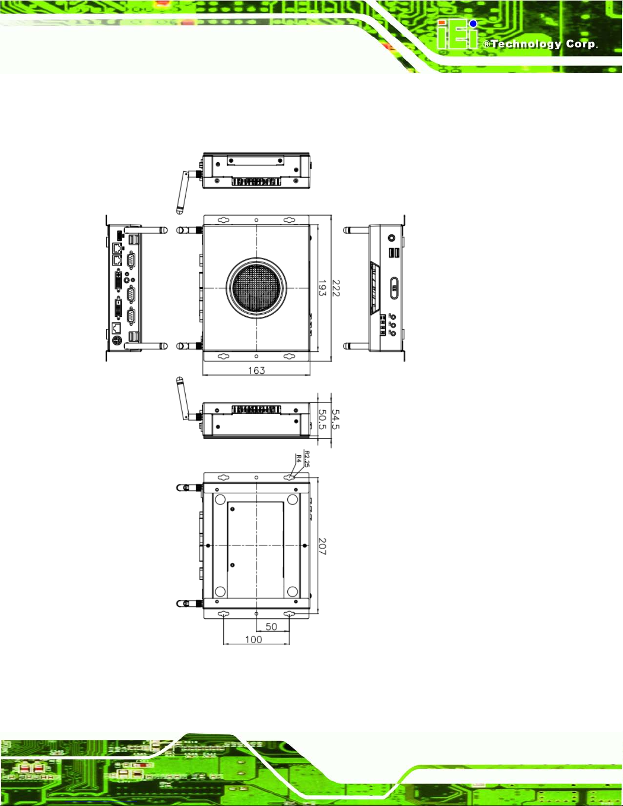
Dimensions
222 (W) x 163 (H) x 54.5 (D) mm
Chassis Construction
SECC + Plastic
Motherboard
CPU
2nd Generation Intel® Core™ i7/i5/i3, Celeron® and Pentium®
desktop processor
Chipset
Intel® H61 (Co-lay Q67 chipset by MOQ limitation)
Ethernet
Intel® 82579 PHY Ethernet (supports Intel® AMT 7.0 with Q67
chipset)
Intel® 82583V Ethernet controller
Page 18

ECN-680A-H61 Embedded System
Page 4
Memo ry
1 x 204-pin 1066/1333 MHz dual-channel DDR3 SDRAM SO-DIMM
slot (system max. 8GB)
Storage
SATA
1 x 2.5'' SATA HDD bay
System Function
USB
4 x USB 2.0 on rear
2 x USB 3.0 on front
Ethernet
2 x RJ-45 Gigabit LAN
RS-232
2 x RS-232 (DB-9 connector)
1 x RS-232 (RJ-45 connector)
RS-422/485
1 x RS-422/485 (DB-9 connector)
Display
1 x HDMI
1 x DVI-D
1 x DVI-I
Resolution
Up to 1920 x 1080 @ 60Hz (DVI-I and DVI-D), 1920 x 1200 @ 60Hz
(HDMI)
Audio
1 x Mic-in, 1 x Line-out, 1 x Line-in on front
Interior Expansions
1 x PCIe Mini slot (reserved for Wi-Fi)
Switch
Reset switch
AT/ATX switch
TPM
TPM-IN01-R11
Watchdog Timer
Software programmable support 1~255 sec. system reset
Power
Power Supply
9V ~ 36V DC input
Power Consumption
19V@3.6A (Intel® Core™ i7-2600S CPU with 1333MHz 4G DDR3
memory)
Reliability
Mounting
Desktop, Wall mount
Operating Temperature
-20°C ~ 60°C
Page 19
ECN-680A-H61 Embedded System
Page 5
Storage Temperature
-30°C ~ 65°C
Operating Humidity
5% ~95%, non-condensing
Operating Shock
Half-sine wave shock 3G, 11ms, 3 shocks per axis
Operating Vibration
Meet MIL-STD-810F 514.5C-2 (with SSD)
Weight (Net/Gross)
1.8 Kg/3.0 Kg
Table 1-2: Technical Specifications
1.5 Front Panel
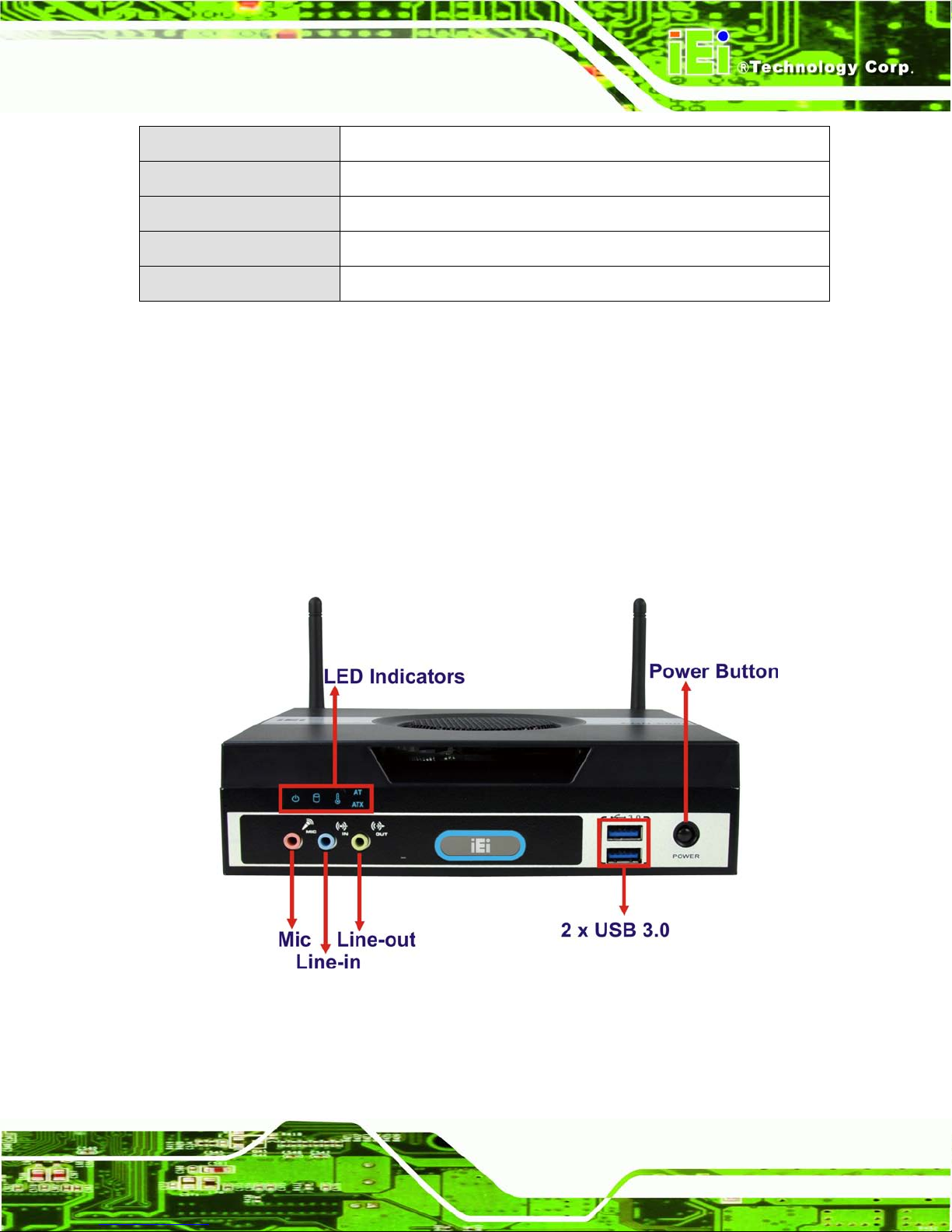
The front panel of the ECN-680A-H61 has the following features (Figure 1-2):
3 x Audio jacks (Mic, Line-in, Line-out)
5 x LED indicators
1 x Power button
2 x USB 3.0 connectors
Figure 1-2: ECN-680A-H61 Front Panel
Page 20
ECN-680A-H61 Embedded System
Page 6
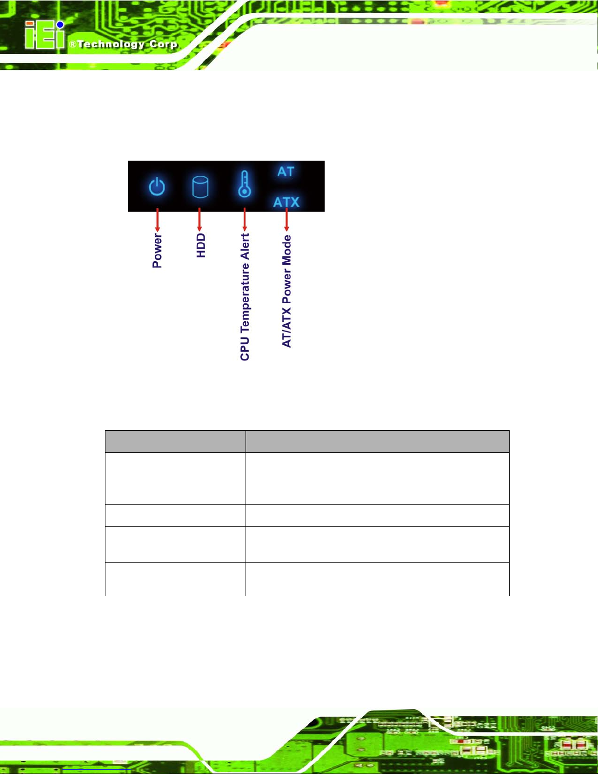
1.5.1 LED Indic ators
There are five LED in dicator lights located along the front panel of the ECN-680A-H61
(Figure 1-3).
Figure 1-3: LED Indicators
The descriptions of each LED indicator are listed below.
LED Indicator Description
Power
Shows power status.
Orange: Standby mode.
Blue: Power-on mode.
HDD
Shows HDD status.
CPU T emperature Alert
Blue: CPU temperature is normal.
Red: CPU temperature is too high.
AT/ATX Mode
Shows the power mode status. Controlled by the AT/ATX
power mode switch.
Table 1-3: LED Indicators
Page 21
ECN-680A-H61 Embedded System
Page 7
NOTE:
If the CPU temperature alert LED shows in red, the user must lower the
environments tem perature or close some running app lications to cool
down the CPU.
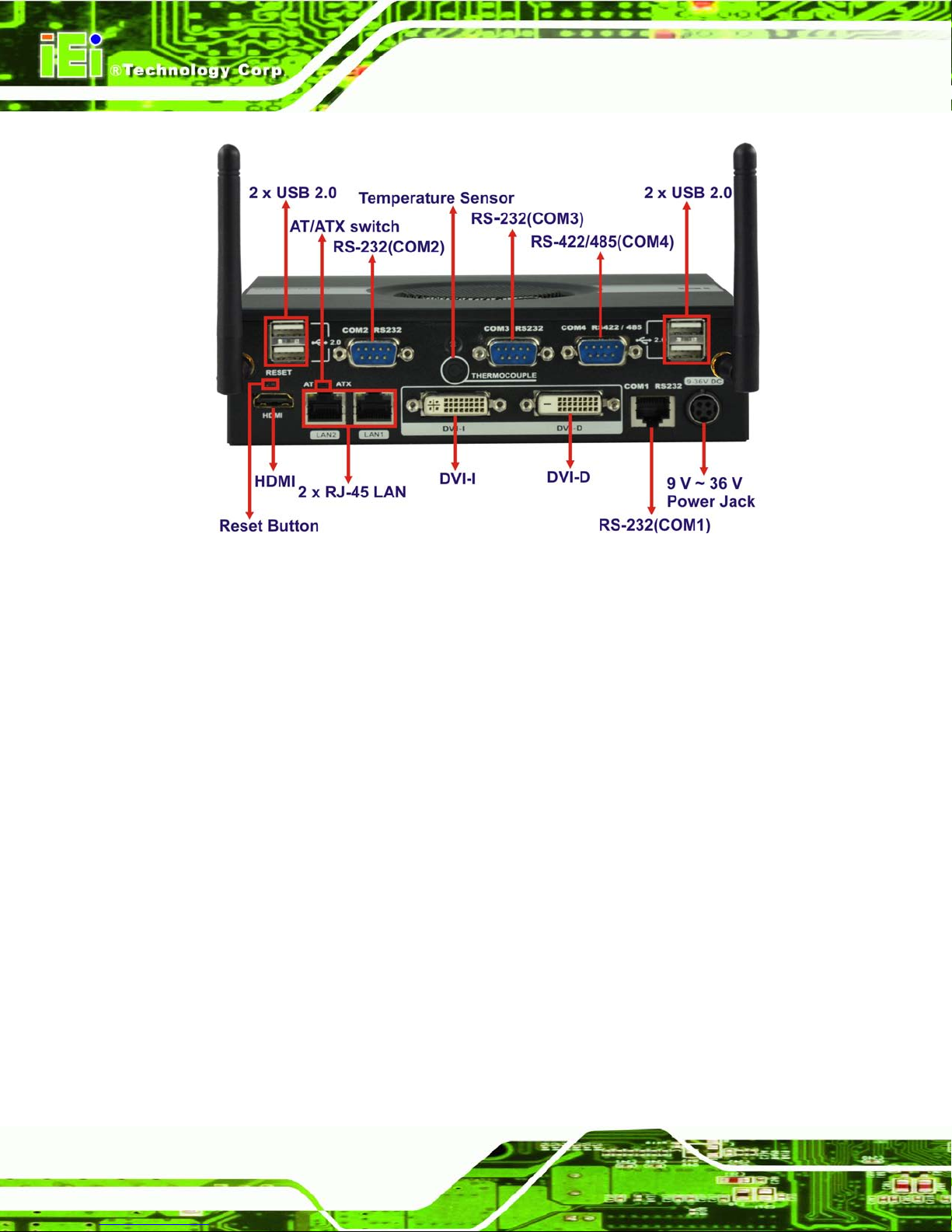
1.6 Rear Panel
The rear panel of the ECN-680A-H61 has the following features (Figure 1-4):
1 x AT/ATX Switch
1 x DVI-D port
1 x DVI-I port
1 x HDMI port
1 x 9 V ~ 36 V power jack
1 x Reset button
2 x RJ-45 LAN connectors
2 x RS-232 (DB-9 connector)
1 x RS-232 (RJ-45 connector)
1 x RS-422/485 (DB-9 connector)
1 x Temperature sensor
4 x USB 2.0 connectors
Page 22
ECN-680A-H61 Embedded System
Page 8
Figure 1-4: ECN-680A-H61 Rear Panel
Page 23
ECN-680A-H61 Embedded System
Page 9
1.7 Dimensions
The physical dimensions are shown below:
Figure 1-5: Physical Dimensions (mm)
Page 24
ECN-680A-H61 Embedded System
Page 10
Chapter
2
2 Unpacking
Page 25
ECN-680A-H61 Embedded System
Page 11
2.1 Anti-s tatic Precautions
WARNING:
Failure to take ESD precautions during installation may result in
permanent damage to the ECN-680A-H61 and severe injury to the
user.
Electrostatic discharge (ESD) can cause serious damage to electronic components,
including the ECN-680A-H61. Dry climates are especially susceptible to ESD. It is
therefore critical th at whenever the ECN-680A-H61 or any other e lectrical component is
handled, the following anti-static precautions are strictly adhered to.
Wear an anti-static wristband: Wearing a simple anti-static wristband can
help to prevent ESD from damaging the board.
Self-grounding: Before handling the board, touch any grounded conducting
material. During the time the board is handled, frequently touch any
conducting materials that are connected to the ground.
Use an anti-static pad: When configuring the ECN-680A-H61, place it on an
antic-static pad. This reduces the possibility of ESD damaging the
ECN-680A-H61.
2.2 Unpacking Precautions
When the ECN-680A-H61 is unpacked, please do the follow ing:
Follow the anti-static precautions outlined in Section
333H2.1.
Make sure the packing box is facing upwards so the ECN-680A-H61 does not
fall out of the box.
Make sure all the components shown in Section
334H2.3 are present.
Page 26

ECN-680A-H61 Embedded System
Page 12
2.3 Unpacking Checklist
NOTE:
If some of the components listed in the checklist below are missing,
please do not proceed with the installation. Contact the IEI resel ler or
vendor you purchased th e ECN-680A-H61 from or contact an IEI sales
representative directl y. To contact an IEI sa les representative, pl ease
send an email to
165Hsales@iei.com.tw.
The ECN-680A-H61 is shipped with the following components:
Quantity Item and Part Number Imag e
1 ECN-680A-H61 multimedia box
1 Power adapter
(P/N: 63040-010090-020-RS)
1 Power cord
(P/N: 32702-000401-100-RS)
1 Power cord convert cable
(P/N: 32000-089400-RS)
2 Mounting brackets
(P/N: 41020-0343C2-00-RS)
8 Mounting bracket screws
(P/N: 44015-030041-RS)
Page 27

ECN-680A-H61 Embedded System
Page 13
Quantity Item and Part Number Imag e
1 RJ-45 to DB-9 COM port cable
(P/N: 32005-000200-200-RS)
2 Wi-Fi antenna (for Wi-Fi model only)
(P/N: 32505-000900-100-RS)
1 Thermal pad
(P/N: 34100-000197-RS)
1 Utility CD
1 One Key Recovery CD
Table 2-1: Package List Contents
Page 28

ECN-680A-H61 Embedded System
Page 14
Chapter
3
3 Installation
Page 29

ECN-680A-H61 Embedded System
Page 15
3.1 Installa tion Precautions
During installation, be aware of the precautions below:
Read the user manual: The user manual provides a complete description of
the ECN-680A-H61, installation instructions and configuration options.
DANGER! Disconnect Power: Power to the ECN-680A-H61 must be
disconnected during the installation process, or before any attempt is made to
access the rear panel. Electric shock and personal injury might occur if the
rear panel of the ECN-680A-H61 is opened while the power cord is still
connected to an electrical outlet .
Qualified Personnel: The ECN-680A-H61 must be installed and operated
only by trained and qualified personnel. Maintenance, upgrades, or repairs
may only be carried out by qualified personnel who are familiar with the
associated dangers.
Grounding: The ECN-680A-H61 should be properly grounded. The voltage
feeds must not be overloaded. Adjust the cabling and provide external
overcharge protection per the electrical values indicated on the label attached
to the back of the ECN-680A-H61.
3.2 Installa tion and Configuration Steps
The following installation steps must be followed.
Step 1: Unpack the ECN-680A-H61.
Step 2: Install the memory module.
Step 3: Install the CPU.
Step 4: Install the HDD.
Step 5: Install the Wi-Fi antenna (Wi-Fi model only).
Step 6: Configure the system.
Step 7: Connect peripheral devices to the ECN-680A-H61.
Step 8: Mount the ECN-680A-H61. Ste p 0:
Page 30

ECN-680A-H61 Embedded System
Page 16
3.3 Me mory Module Installation
To install the memory module, please follow the steps below:
Step 1: Remove two retention screws from the right side, two from the left side and one
from the rear panel, as shown in
335HFigure 3-1.
Figure 3-1: Retention Screws Removal
Step 2: Remove the top cover from the device.
Step 3: Remove the eight fan bracket retention screws and disconnect the fan
connector (CPU_FAN1), as shown in
335HFigure 3-2.
Figure 3-2: Fan Removal
Page 31

ECN-680A-H61 Embedded System
Page 17
Step 4: Lift the fan module out of the ECN-680A-H61 and locate the SO-DIMM socket
(
336HFigure 3-3).
Figure 3-3: SO-DIMM Socket Location
Step 5: Install the DDR3 memory module by pushing it into the socket at an angle
(
543HFigure 3-4).
Step 6: Gently pull the spring retainer clips of the SO-DIMM socket out and push the
rear of the DDR3 memory module down (
544HFigure 3-4).
Step 7: Release the spring retainer clips on the SO-DIMM socket. They clip into place
and secure the DDR3 memory module in the socket.
Figure 3-4: DDR3 SO-DIMM Module Installation
Page 32
ECN-680A-H61 Embedded System
Page 18
Step 8: Install the fan module in the same position it was before and tighten the eight fan
bracket retention screws.
Step 9: Connect the fan connector (CPU_FAN1).
Step 10: Replace the cover and secure it using five previously removed retention screws.
3.4 CPU In s t allation
WARNING:
CPUs are expensive and sensitive components. When installing the
CPU, please be car ef ul not to damage it in anyway. Do NOT touc h the
pins at the bottom of the CPU. When handling the CPU, only hold it on
the sides.
To install the CPU, please follow the steps below:
Step 1: Remove the top cover from the device. See Section 3.3.
Step 2: Remove the fan module. See Section 3.3.
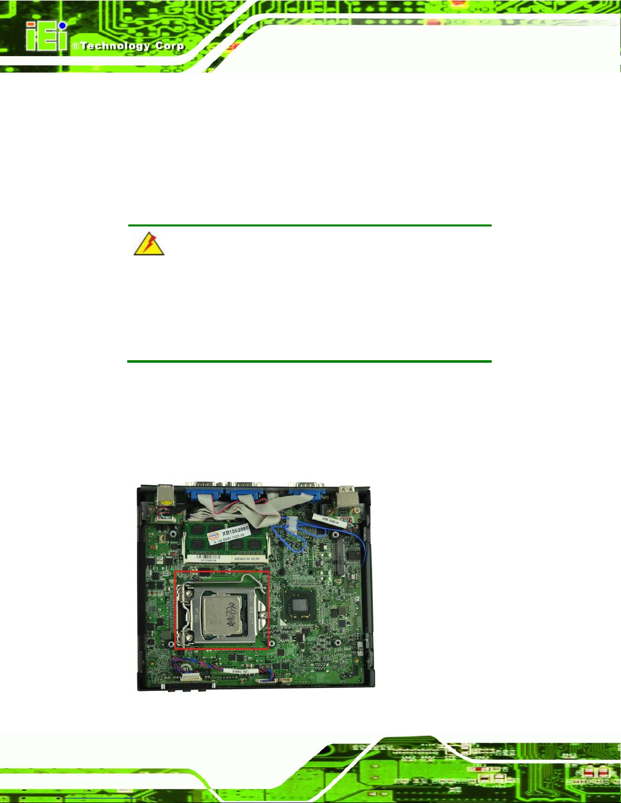
Step 3: Locate the CPU socket (
336HFigure 3-5).
Figure 3-5: CPU Socket Location
Page 33
ECN-680A-H61 Embedded System
Page 19
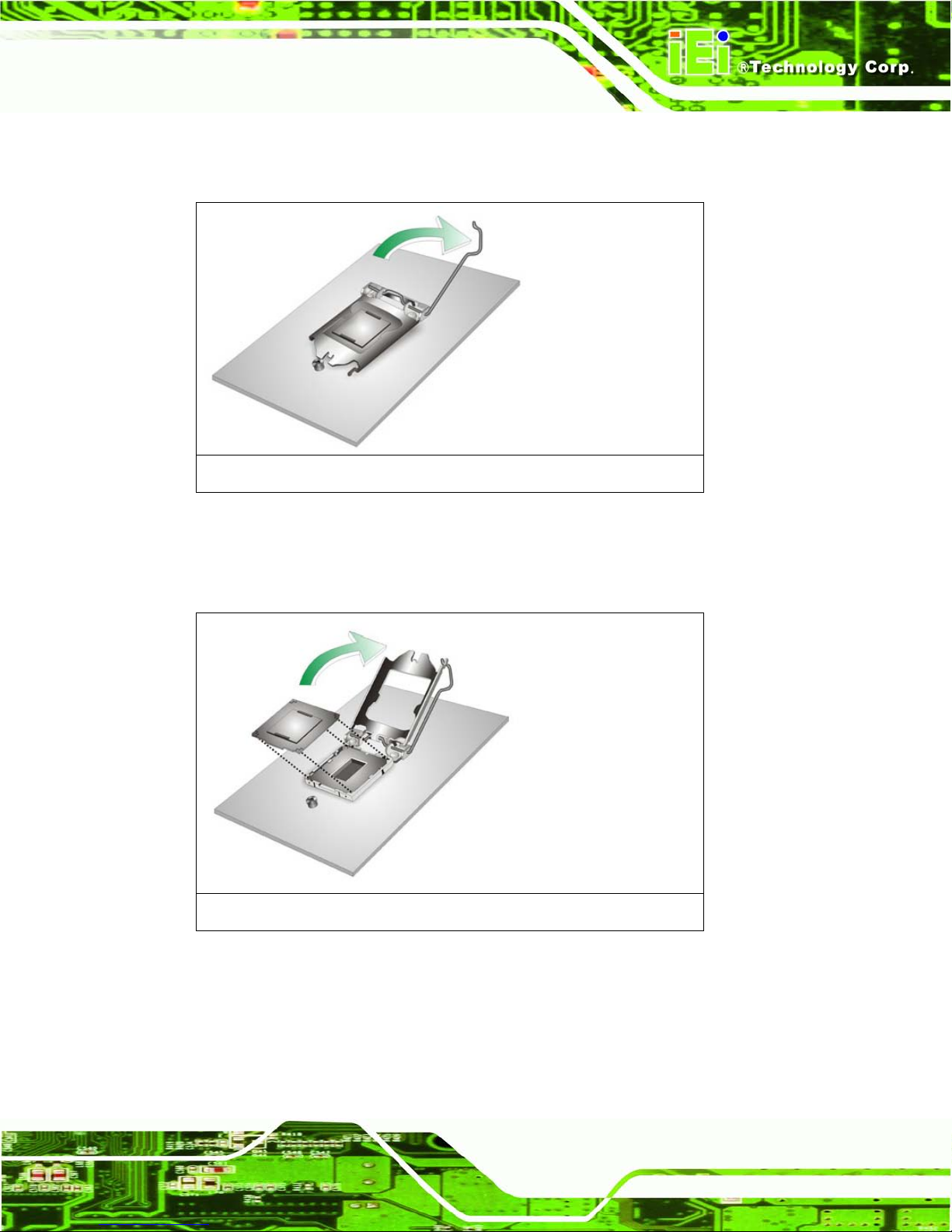
Step 4: Disengage the load lever by pressing the lever down and slightly outwards to
clear the retention tab. Fully open the lever. See Figure 3-6.
Figure 3-6: Disengage the CPU Socket Load Lever
Step 5: Open the socket and remove the protective cover. The black protective
cover can be removed by pulling up on the tab labeled “Remove”. See Figure
3-7.
Figure 3-7: Remove Protective Cover
Step 6: Inspect the CPU socket. Make sure there are no bent pins and make sure the
socket contacts are free of foreign material. If any debris is found, remove it with
compressed air.
Page 34
ECN-680A-H61 Embedded System
Page 20
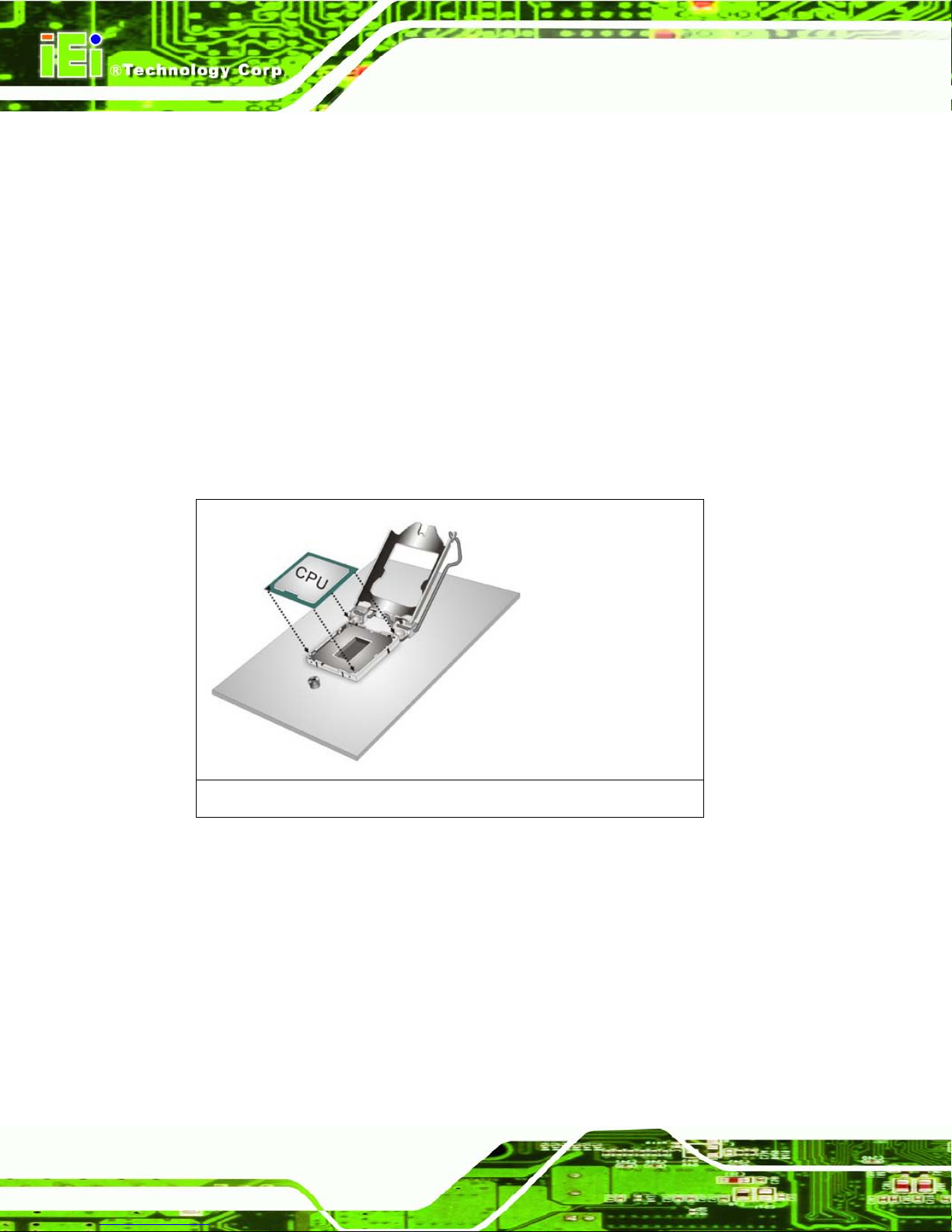
Step 7: Orientate the CPU properly. The contact array should be facing the CPU
socket.
Step 8: Correctly position the CPU. Match the Pin 1 mark with the CPU edge on the
CPU socket.
Step 9: Align the CPU pins. Locate pin 1 and the two orientation notches on the CPU.
Carefully match the two orientation notches on the CPU with the socket
alignment keys.
Step 10: Insert the CPU. Gently insert the CPU into the socket. If the CPU pins are
properly aligned, the CPU should slide into the CPU socket smoothly. See
Figure 3-8.
Figure 3-8: Insert the CPU
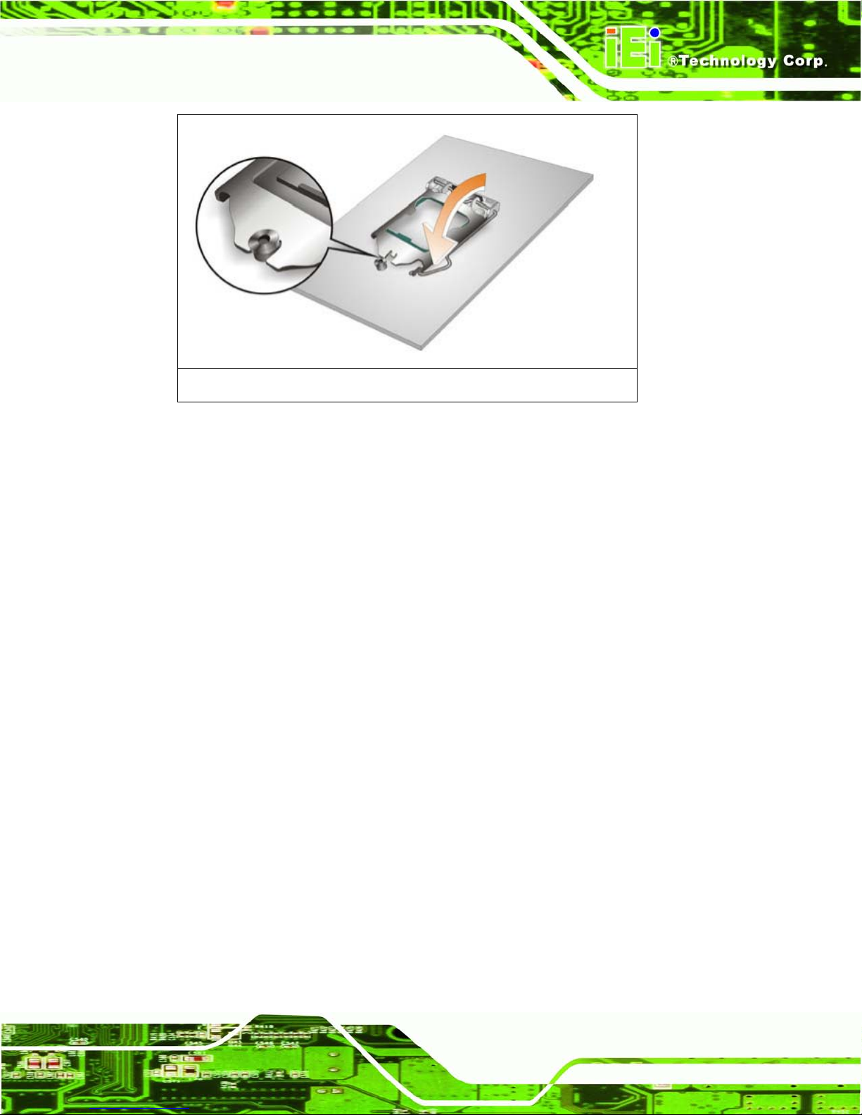
Step 11: Close the CPU socket. Close the load plate and pull the load back a little to
have the load plate be able to secure to the knob. Engage the load lever by
pushing it back to its original position. See Figure 3-9. There will be some
resistance, but will not require extreme pressure.
Page 35
ECN-680A-H61 Embedded System
Page 21
Figure 3-9: Close the CPU Socket
Step 12: Install the fan module in the same position it was before and tighten the eight fan
bracket retention screws. See Section 3.3.
Step 13: Connect the fan connector (CPU_F AN1). See Section 3.3.
Step 14: Replace the cover and secure it using five previously removed retention screws.
See Section 3.3.
3.5 Har d Disk Driv e (HDD) Installat ion
To install the hard drive, please follow the steps below:
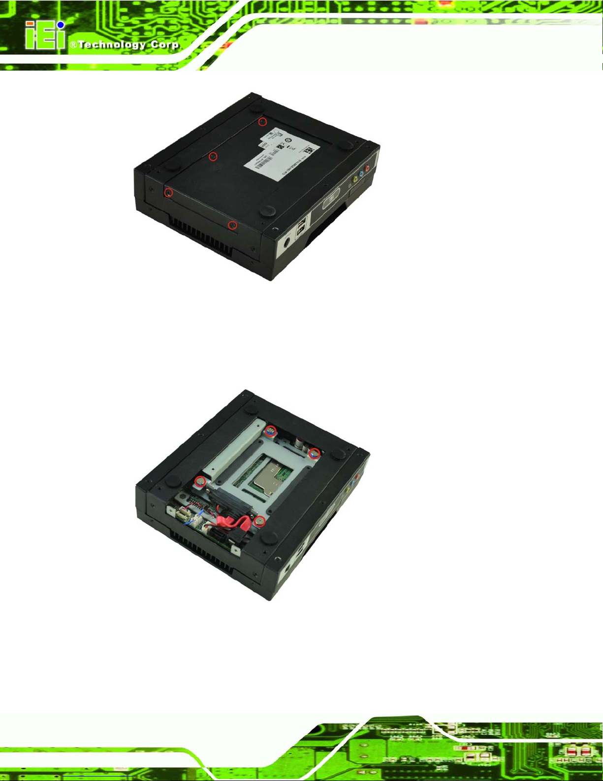
Step 1: Remove four (4) retention screws from the HDD cover, two from the bottom
panel and two from the right side, as shown in
335HFigure 3-10.
Page 36
ECN-680A-H61 Embedded System
Page 22
Figure 3-10: HDD Cover Retention Screws
Step 2: Remove the HDD cover from the device.
Step 3: Loosen the four HDD bracket retention screws (
336HFigure 3-11).
Figure 3-11: HDD Bracket Retention Screws
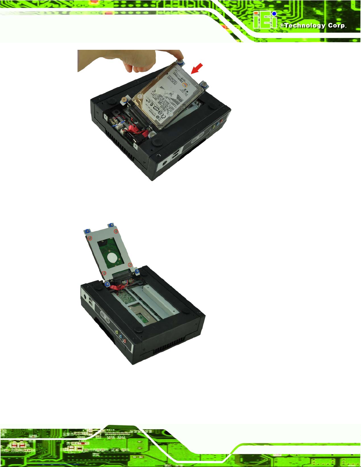
Step 4: Lift the HDD bracket out of the ECN-680A-H61 and slide the HDD to the HDD
bracket (
336HFigure 3-12).
Page 37
ECN-680A-H61 Embedded System
Page 23
Figure 3-12: Inserting the HDD
Step 5: Secure the HDD to the HDD bracket using four retention screws (
336HFigure 3-13).
Figure 3-13: HDD Retention Screws
Page 38
ECN-680A-H61 Embedded System
Page 24
Step 6: Install the HDD bracket in the same position it was before and tighten the HDD
bracket retention screws.
Step 7: Reinstall the HDD cover.
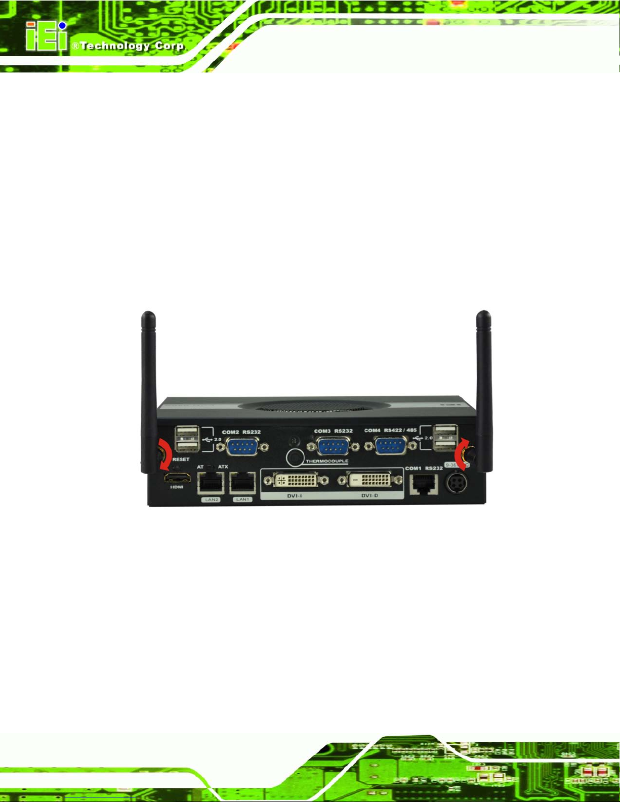
3.6 Wi-Fi Antenna Ins tallation (Wi-Fi Model Only)
To install the Wi-Fi antennas to the ECN-680A-H61 series for efficient wireless network
transmission, follow the steps below.
Step 1: Locate the antenna con nec tor s on the rear panel of the embedded system.
Step 2: Install the antennas to the antenna connectors (
767H767HFigure 3-14).
Figure 3-14: Wi-Fi Antenna In stallation
3.7 AT/ATX Mode Se lection
AT or ATX power mode can be used on the ECN-680A-H61. The selection is made
through an AT/ATX switch located on the rear panel (Figure 3-15). To select AT mode or
ATX mode, follow the steps below.
Step 1: Locate the AT/ATX switch on the rear panel (Figure 3-15).
Page 39

ECN-680A-H61 Embedded System
Page 25
Figure 3-15: AT/ATX Switch Locatio n
Step 2: Adjust the A T/ATX switch. S tep 0:
3.7.1 AT P ower Mode
With the AT mode selec ted, the po wer is control led by a central power unit rather than a
power switch. T he ECN-680A-H61 panel PC turns on automatically when the power is
connected. The AT mode benefits a production lin e to control multi ple panel PCs from a
central management center and other applications including:
ATM
Self-service kiosk
Plant environment monitoring system
Factory automation platform
Manufacturing shop flow
3.7.2 ATX Power Mode
With the ATX mode selected, the ECN-680A-H61 panel PC goes in a standby mode when
it is turned off . The panel PC can be easily turned on via ne twork or a power switch in
standby mode. Remote power control is perfect for advertising applications since the
broadcasting time for each panel PC can be set individually and controlled remotely. Other
possible application includes:
Page 40
ECN-680A-H61 Embedded System
Page 26
Security surveillance
Point-of-Sale (POS)
Advertising terminal
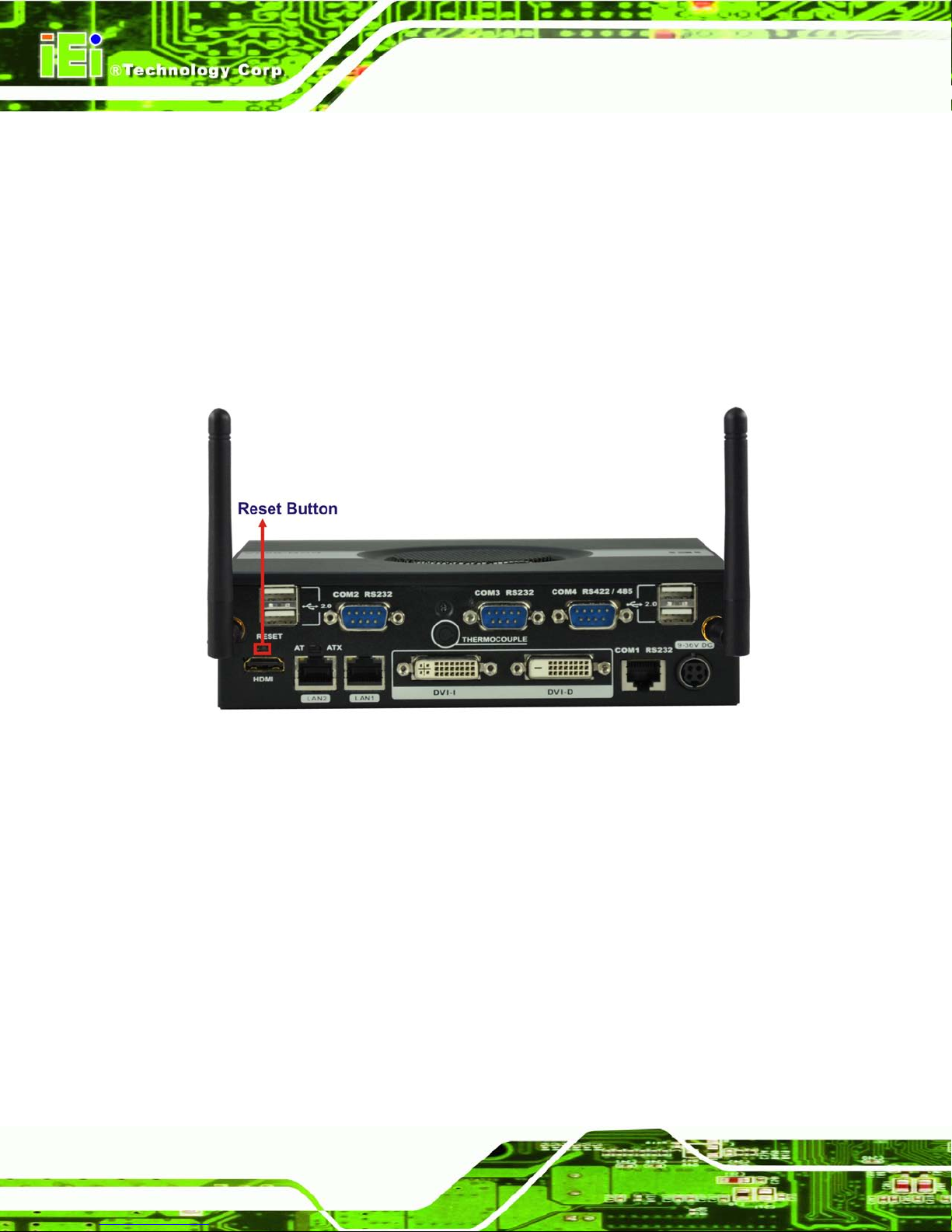
3.8 Reset the System
The reset button en ables user to reboot the system when the system is turned on. To
reboot the system, follow the steps below.
Step 1: Locate the reset button on the rear panel (Figure 3-5).
Figure 3-16: Reset Button Location
Step 2: Press the reset button. Step 0:
3.9 Powering On/Off the Sys tem
To power on the system, follow the steps below:
Step 1: Press the power button on the front panel for 3 seconds (Figure 3-17).
Step 2: Once turned on, the power LED should light up.
To power off the system, follow the steps below:
Step 1: Press the power button on the front panel for 6 seconds (Figure 3-17).
Page 41

ECN-680A-H61 Embedded System
Page 27
Step 2: Once turned off, the power LED will be off.
Figure 3-17: Power Button Location
3.10 Mou n t the System
The ECN-680A-H61 supports wall mounting. The bottom panel of the ECN-680A-H61
contains four screw holes for mounting (Figure 3-18) the system.
Figure 3-18: Mounting Screw Holes
Page 42

ECN-680A-H61 Embedded System
Page 28
3.10.1 Mounting the System with Mounting Brackets
To mount the embedded system onto a wall or some other surface using the two mounting
brackets, please follow the steps below.
Step 1: Turn the embedded system over.
Step 2: Align the two retention screw holes in each bracket with the corresponding
retention screw holes on the sides of the bottom surface.
Step 3: Secure the brackets to the system by inserting two retention screws into each
bracket as illustrated in
340HFigure 3-19.
Figure 3-19: Mounting Bracket Retention Screws
Step 4: Drill holes in the intended installation surface.
Step 5: Align the mounting holes in the sides of the mounting brackets with the predrilled
holes in the mounting surface.
Page 43

ECN-680A-H61 Embedded System
Page 29
NOTE:
To have the best system heat dissipation, please make sure to face the
I/O panel downward (
341HFigure 3-19) when mounting the system.
Step 6: Insert four retention screws, two in each bracket, to secure the system to the
wall. S tep 0:
3.11 External Peripheral Interface Connectors
The following external peripheral devices can be connected to the external peripheral
interface connectors.
Audio devices
DVI devices
HDMI devices
RJ-45 Ethernet cable connector
Serial devices
USB devices
To install these devices, connect the corresponding cable connector from the actual
device to the corresponding ECN-680A-H61 external peripheral interface connector
making sure the pins are properly aligned.
Page 44

ECN-680A-H61 Embedded System
Page 30
Figure 3-20: Peripheral Connecto rs (Front Panel)
Figure 3-21: Peripheral Connectors (Rear Panel)
Page 45

ECN-680A-H61 Embedded System
Page 31
3.11.1 Au dio Connector
The audio jacks on the front panel enable the ECN-680A-H61 to be connected to a stereo
sound setup. To install the audio devices, follow the steps below.
Step 1: Identify the audio plugs. The plugs on your home theater system or speakers
may not match the colors on the rear panel. If audio plugs are plugged into the
wrong jacks, sound quality will be very bad.
Step 2: Plug the audio plugs into the audio jacks. Plug the audio plugs into the audio
jacks. If the plugs on your speakers are different, an adapter will need to be used
to plug them into the audio jacks.
Line In port (Light Blue): Connects a CD-ROM, DVD player, or other audio
devices.
Microphone (Pink): Connects to a microphone.
Line Out port (Lime): Connects to headphones or speakers.
Figure 3-22: Audio Connector
Step 3: Check audio clarity. Check that the sound is coming through the right speakers
by adjusting the balance front to rear and left to right. Step 0:
Page 46

ECN-680A-H61 Embedded System
Page 32
3.11.2 DVI Display Device Connection
The ECN-680A-H61 has one female DVI-I connector a nd one female DVI-D connector on
the rear panel. The DVI connectors are connected to digital display devices. To connect a
digital display device to the ECN-680A-H61, please follow the instructions below.
Step 1: Locate the DVI connector. The location of the DVI connector is shown in
Chapter 1.
Step 2: Align the DVI connector. Align the male DVI connector on the digital display
device cable with the female DVI connector on the external peripheral interface.
Step 3: Insert the DVI connector. Once the connectors are properly aligned with the
male connector, insert the male connector from the digital display device into the
female connector on the ECN-680A-H61. See
359HFigure 3-23.
Figure 3-23: DVI Connector
Step 4: Secure the connector . Secure the DVI connector from the digital display device
to the external interface by tightening the two retention screws on either side of
the connector.
Page 47

ECN-680A-H61 Embedded System
Page 33
3.11.3 HDMI Device Connection
The HDMI connector trans mits a digital signal to compati ble HDMI display devices such
as a TV or computer screen. To connect the HDMI cable to the ECN-680A-H61, follow the
steps below.
Step 1: Locate the HDMI connector. The location is shown in Chapter 1.
Step 2: Align the connector. Align the HDMI connector with the HDMI port. Make sure
the orientation of the connector is correct.
Figure 3-24: HDMI Connection
Step 3: Insert the HDMI connector. Gently insert the HDMI connector . The connector
should engage with a gentle push. If the connector does not insert easily, check
again that the connector is aligned correctly, and that the connector is being
inserted with the right way up.
3.11.4 LAN Connection
There are two external RJ-45 LAN connectors. The RJ -45 connector ena bles connecti on
to an external networ k. To connect a LAN cab le with an RJ-45 connec tor, please follow
the instructions below.
Page 48

ECN-680A-H61 Embedded System
Page 34
Step 4: Locate the RJ-45 connectors. The location of the LAN connector is shown in
Chapter 1.
Step 5: Align the connectors. Align the RJ-45 connector on the LAN cable with one of
the RJ-45 connectors on the ECN-680A-H61. See
360HFigure 3-25.
Figure 3-25: LAN Connection
Step 6: Insert the LAN cable RJ-45 connector. Once aligned, gently insert the LAN
cable RJ-45 connector into the RJ-45 connector. Step 0:
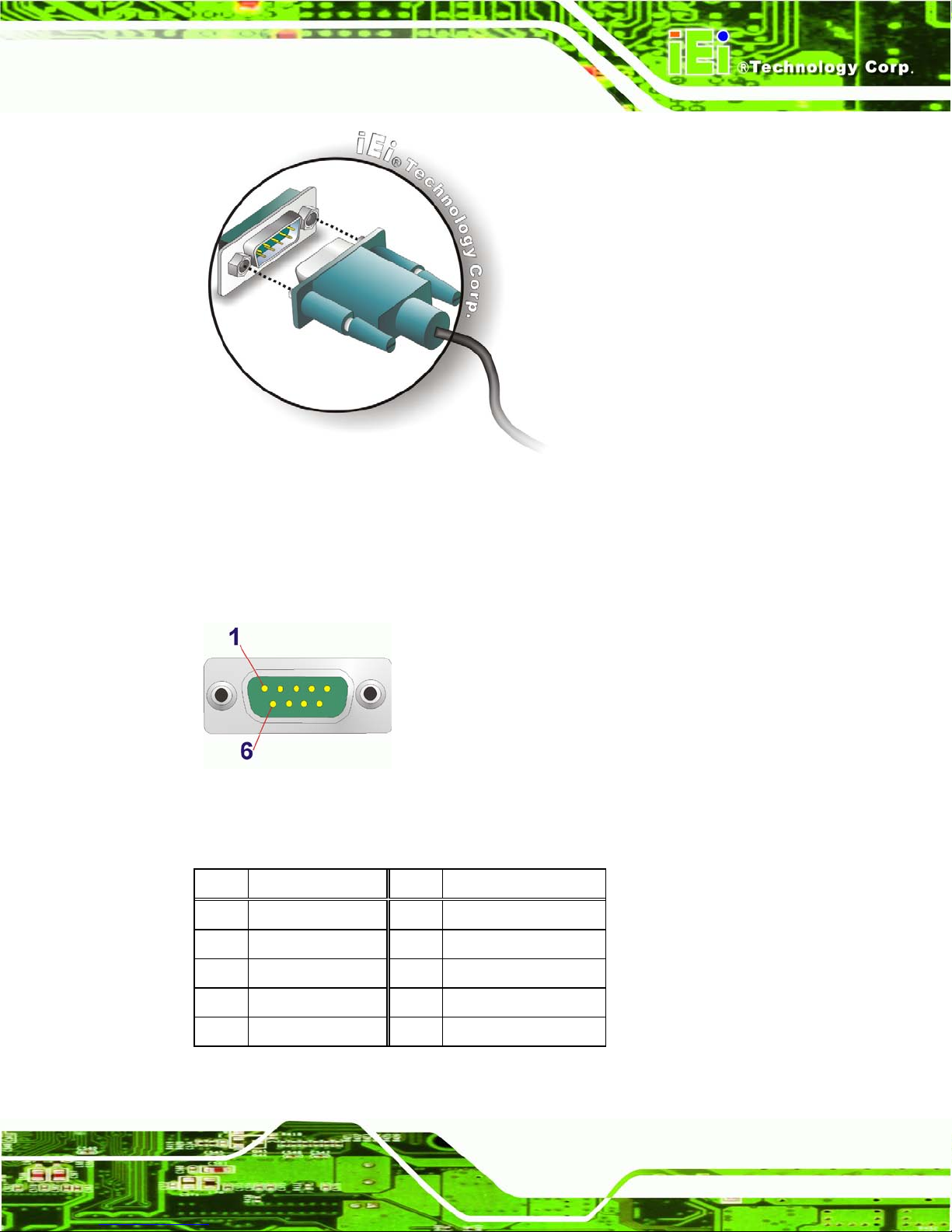
3.11.5 DB-9 Serial Port Connection
There are two RS-232 DB-9 connectors and one RS-422/485 DB-9 connector of the
ECN-680A-H61 for serial dev ice connection. Follow the steps below to connec t a serial
device to the DB-9 connector of the ECN-680A-H61.
Step 1: Locate the DB-9 connector. The locations of the DB-9 connectors are shown
in Chapter 1.
Step 2: Insert the serial connect o r . Insert the DB-9 connector of a serial device into
the DB-9 connector on the rear panel. See Figure 3-26.
Page 49
ECN-680A-H61 Embedded System
Page 35
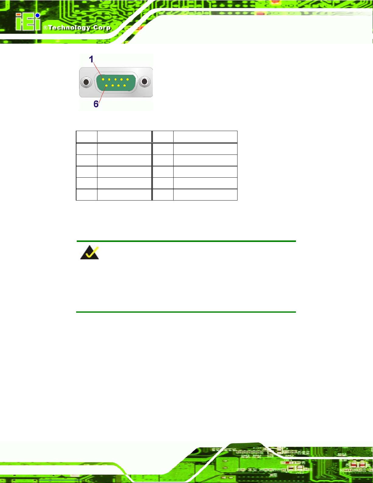
Figure 3-26: DB-9 Serial Port Connector
Step 3: Secure the connector. Secure the serial device connector to the external
interface by tightening the two retention screws on either side of the connector.
Step 0:
Figure 3-27: DB-9 Connector Pinout Location
The pinouts of the RS-232 serial ports are shown below.
Pin Description Pin Description
1 -NDCD2 2 -NDSR2
3 NSIN2 4 -NRTS2
5 NSOUT2 6 -NCTS2
7 -NDTR2 8 -XRI2
9 GND 10 N/A
Table 3-1: RS-232 Serial Port s Pinouts (COM2)
Page 50
ECN-680A-H61 Embedded System
Page 36
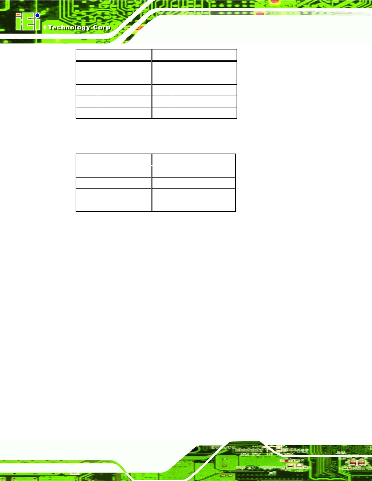
Pin Description Pin Description
1 -NDCD3 2 -NDSR3
3 NSIN3 4 -NRTS3
5 NSOUT3 6 -NCTS3
7 -NDTR3 8 -XRI3
9 GND 10 N/A
Table 3-2: RS-232 Serial Port s Pinouts (COM3)
The pinouts of the RS-422/485 serial port are shown below.
Pin Description Pin Description
1 RXD485# 2 N/A
3 RXD485 4 N/A
5 TXD485 6 N/A
7 TXD485# 8 N/A
Table 3-3: RS-422/485 Serial Port Pinouts (COM4)
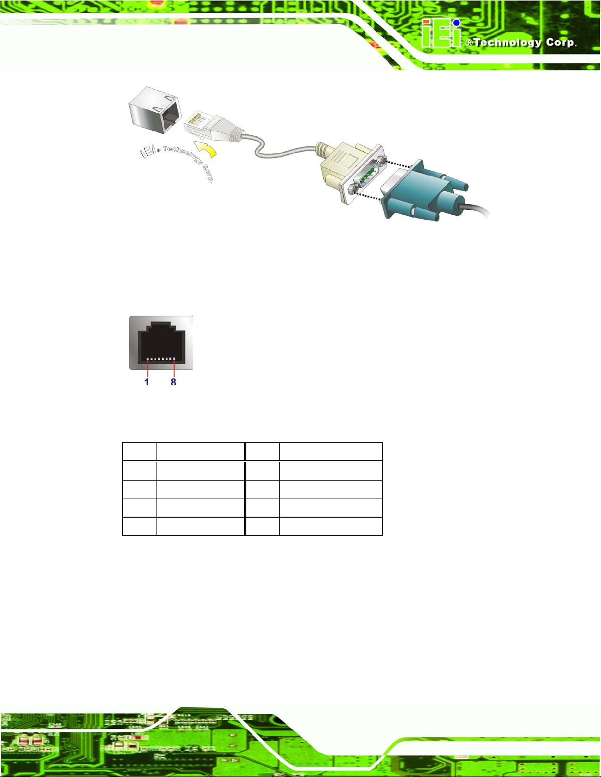
3.11.6 RJ-45 Seria l Port Connection
There is one RJ-45 connector of the ECN-680A-H61 for serial device connectio n. Follow
the steps below to connect a serial device to the RJ-45 serial port connector of the
ECN-680A-H61.
Step 1: Locate the RJ-45 serial port. The location of the RJ-45 serial port is shown in
Chapter 1.
Step 2: Connect the RJ-45 to COM port cable to the ECN-680A-H61. Insert the RJ-45
connector end of cable into the RJ-45 serial port. See Figure 3-28.
Step 3: Connect the serial device. Connect a serial device to the DB-9 connector end
of the cable. See Figure 3-28.
Page 51
ECN-680A-H61 Embedded System
Page 37
Figure 3-28: RJ-45 Serial Port Connector
Step 4: Secure the connector. Secure the serial device connector to the external
interface by tightening the two retention screws on either side of the connector.
Step 0:
Figure 3-29: RJ-45 RS-232 Serial Port Pi n o u t L o cation
The pinouts of the RJ45 RS-232 serial port are shown below.
Pin Description Pin Description
1 DCD1 2 DSR1
3 SIN1 4 RTS1
5 SOUT1 6 CTS1
7 DTR1 8 RI1
Table 3-4: RS-232 Serial Port s Pinouts (COM1)
Page 52
ECN-680A-H61 Embedded System
Page 38
Figure 3-30: DB-9 Connector Pinout Location
Pin Description Pin Description
1 DCD 2 RXD
3 TXD 4 DTR
5 GND 6 DSR
7 RTS 8 CTS
9 RI
Table 3-5: DB-9 Serial Po r t s Pinouts
3.11.7 USB Device Connection
NOTE:
User must install the USB 3.0 driver before connecting a USB device to
the system or else the system may not recognize the connected
device.
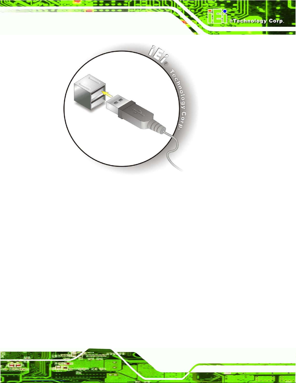
There are four USB 2.0 connectors and two U SB 3.0 connector s on the ECN-680A-H61.
To connect a USB device, please follow the instructions below.
Step 1: Locate the USB connectors. The locations of the USB connectors are shown
in Chapter 1.
Step 2: Align the connectors. Align the USB device connector with one of the
connectors on the external peripheral interface. See Figure 3-31.
Page 53
ECN-680A-H61 Embedded System
Page 39
Figure 3-31: USB Device Connection
Step 3: Insert the device connector. Onc e al ign ed, ge ntly insert the USB device
connector into the onboard connector.
Page 54
ECN-680A-H61 Embedded System
Page 40
Chapter
4
4 System Motherboard
Page 55

ECN-680A-H61 Embedded System
Page 41
4.1 Overview
The ECN-680A-H611 embedded system motherboard comes with a number of per iph eral
interface connectors and configuration jumpers.
4.1.1 Layout
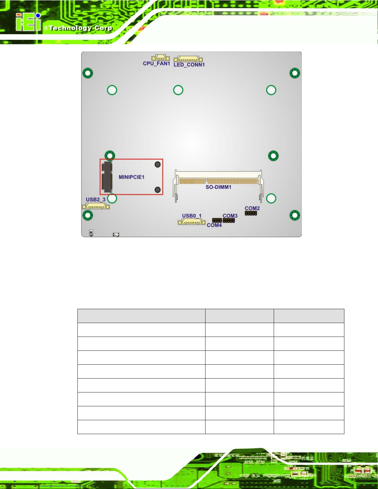
The connector locations are shown in Figure 4-1. The connector pinouts for these
connectors are listed in the following sections.
Figure 4-1: Connector and Jumper Locations (Front Side)
Page 56
ECN-680A-H61 Embedded System
Page 42
Figure 4-2: Connector and Jumper Locations (Rear Side)
4.1.2 Peripheral Interface Connectors
The table below shows a list of the peripheral interface connectors on the ECN-680A-H61.
Detailed descriptions of these connectors can be found below.
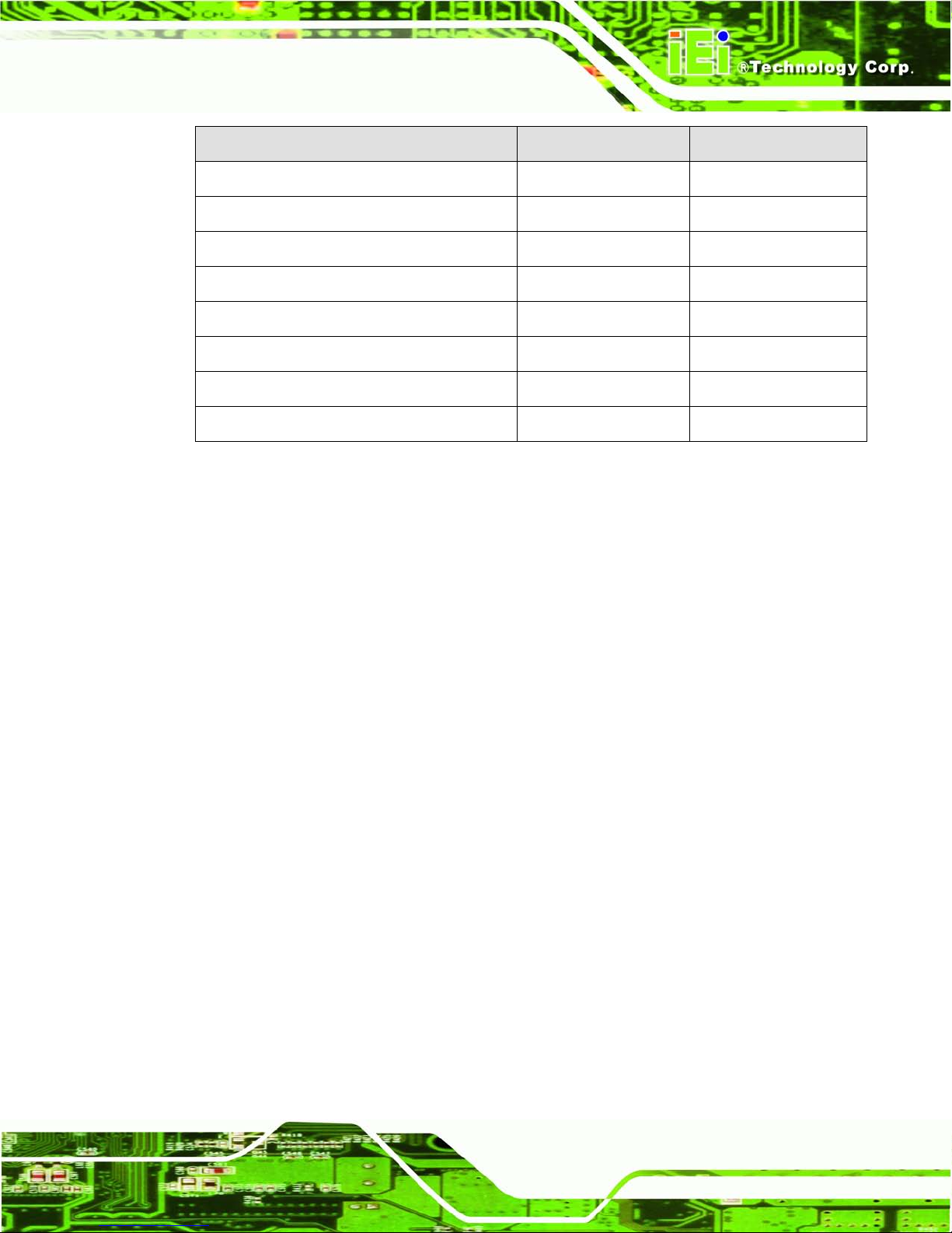
Connector Type Label
Battery connector 2-pin wafer BAT1
Fan connector (CPU) 4-pin wafer CPU_FAN1
LED module connector 10-pin wafer LED_CONN1
Logo LED connectors 2-pin header LED1, LED2, LED3
PCIe Mini card slot PCIe Mini card slot MINIPCIE1
RS-232 serial ports 10-pin header COM2, COM3
RS-422/485 serial port 8-pin header COM4
SATA connectors SATA connector SATA1, SATA2
Page 57
ECN-680A-H61 Embedded System
Page 43
Connector Type Label
SATA power connectors 2-pin wafer CN1, CN2
SMBus connector 4-pin wafer SMBUS1
SO-DIMM connector SO-DIMM connector SO-DIMM1
Speaker connector 4-pin wafer SPEAKER1
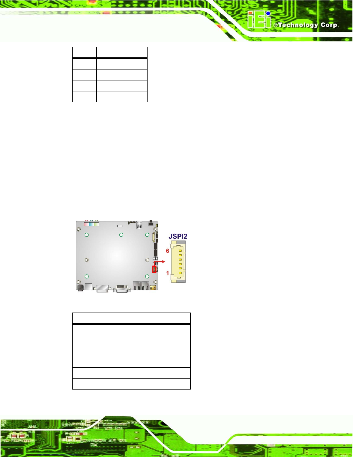
SPI Flash connector 6-pin wafer JSPI2
SPI Flash connector (EC) 6-pin wafer JSPI1
K Type thermocouple connectors 2-pin wafer CN5, CN6
USB 2.0 connectors 9-pin wafer USB0_1, USB2_3
Table 4-1: Peripheral Interface Connectors
4.2 Internal Peripheral Connectors
Internal peripheral connectors are found on the motherboard and are only accessible
when the motherboard is outside of the chassis. This section has complete descriptions of
all the internal, peripheral connectors on the ECN-680A-H61.
4.2.1 Battery Connector
CN Label: BAT1
CN T y pe:
2-pin wafer
CN Location: See Figure 4-3
CN Pinouts: See Table 4-2
This is connected to the system battery. The battery provides power to the sy stem clock to
retain the time when power is turned off.
Page 58

ECN-680A-H61 Embedded System
Page 44
Figure 4-3: Battery Connector Location
Pin Description
1 Battery+
2 Ground
Table 4-2: Battery Connector Pinouts
4.2.2 Fan Connector (CPU)
CN Label: CPU_FAN1
CN T y pe:
4-pin wafer
CN Location: See Figure 4-4
CN Pinouts: See Table 4-3
The fan connector attaches to a CPU cooling fan.
Page 59

ECN-680A-H61 Embedded System
Page 45
Figure 4-4: CPU Fan Connector Location
Pin Description
1
GND
2
+V12S
3
FANPWM1
4
FANIN1
Table 4-3: CPU Fan Connector Pinouts
4.2.3 LED Module Connector
CN Label: LED_CONN1
CN T y pe:
10-pin wafer
CN Location: See Figure 4-5
CN Pinouts: See Table 4-4
The LED module connector connects to a LED module that shows indicators on the
system front panel.
Page 60

ECN-680A-H61 Embedded System
Page 46
Figure 4-5: LED Module Connector Location
Pin Description
1 3.3VALWAYS
2 LED_GND
3 LED_GND
4 PWR_ON_LED#
5 CPU_TEMP_H#
6 CPU_TEMP_L#
7 SUS_LED#
8 SATA_LED#
9 AT_LED#
10 ATX_LED#
Table 4-4: LED Module Connector Pinouts
4.2.4 Logo LED Connectors
CN Label: LED1, LED2, LED 3
CN T y pe:
2-pin header
CN Location: See Figure 4-6
CN Pinouts: See Table 4-5
Use the Logo LED Connector to connect to the logo LED on the front panel.
Page 61

ECN-680A-H61 Embedded System
Page 47
Figure 4-6: Logo LED Connector Locations
Pin Description
1 +V5A
2 GND
Table 4-5: Logo LED Connector Pinouts
4.2.5 PCIe Min i C ard Slot
CN Label: MINIP CIE1
CN T y pe:
PCIe Mini card slot
CN Location: See Figure 4-7
CN Pinouts: See Table 4-6
The PCIe Mini card s lot enables a PCIe Mini card expans ion module to be c onnected to
the board.
Page 62

ECN-680A-H61 Embedded System
Page 48
Figure 4-7: PCIe Mini Card Slot Location
Pin Description Pin Description
1 PCIE_WAKE# 2 VCC3
3 N/C 4 GND
5 N/C 6 1.5V
7 N/C 8 N/C
9 GND 10 N/C
11 CLK- 12 N/C
13 CLK+ 14 N/C
15 GND 16 N/C
17 PCIRST# 18 GND
19 N/C 20 VCC3
21 GND 22 PCIRST#
23 PERN2 24 3VDual
25 PERP2 26 GND
27 GND 28 1.5V
29 GND 30 SMBCLK
31 PETN2 32 SMBDATA
33 PETP2 34 GND
35 GND 36 USBD37 N/C 38 USBD+
39 N/C 40 GND
Page 63

ECN-680A-H61 Embedded System
Page 49
41 N/C 42 N/C
43 N/C 44 N/C
45 N/C 46 N/C
47 N/C 48 1.5V
49 N/C 50 GND
51 N/C 52 VCC3
Table 4-6: PCIe Mini Card Slot Pinouts
4.2.6 RS-232 S erial Port Connectors
CN Label: C OM2 , C OM3
CN T y pe:
10-pin header
CN Location: See Figure 4-8
CN Pinouts: See Table 4-7
The 10-pin serial port connector provides one RS-232 serial communications channel.
The COM serial port connector can be connected to an external RS-232 serial port device.
Figure 4-8: RS-232 Serial Port Connector Location
Pin Description Pin Description
1 -NDCD2 6 -NCTS2
2 -NDSR2 7 -NDTR2
3 NSIN2 8 -XRI2
4 -NRTS2 9 GND
Page 64

ECN-680A-H61 Embedded System
Page 50
5 NSOUT2 10 N/A
Table 4-7: Serial Port Connector Pinouts (COM2)
Pin Description Pin Description
1 -NDCD3 6 -NCTS3
2 -NDSR4 7 -NDTR3
3 NSIN3 8 -XRI3
4 -NRTS3 9 GND
5 NSOUT3 10 N/A
Table 4-8: Serial Port Connector Pinouts (COM3)
4.2.7 RS-422/485 Serial Port Connector
CN Label: COM4
CN T y pe:
8-pin header
CN Location: See Figure 4-9
CN Pinouts: See Table 4-9
This connector provides RS-422 or RS-485 communications.
Figure 4-9: RS-422/485 Serial Port Connector Location
Pin Description Pin Description
1 RXD485# 2 N/A
3 RXD485 4 N/A
Page 65
ECN-680A-H61 Embedded System
Page 51
5 TXD485 6 N/A
7 TXD485# 8 N/A
Table 4-9: RS-422/485 Serial Port Connector Pinouts
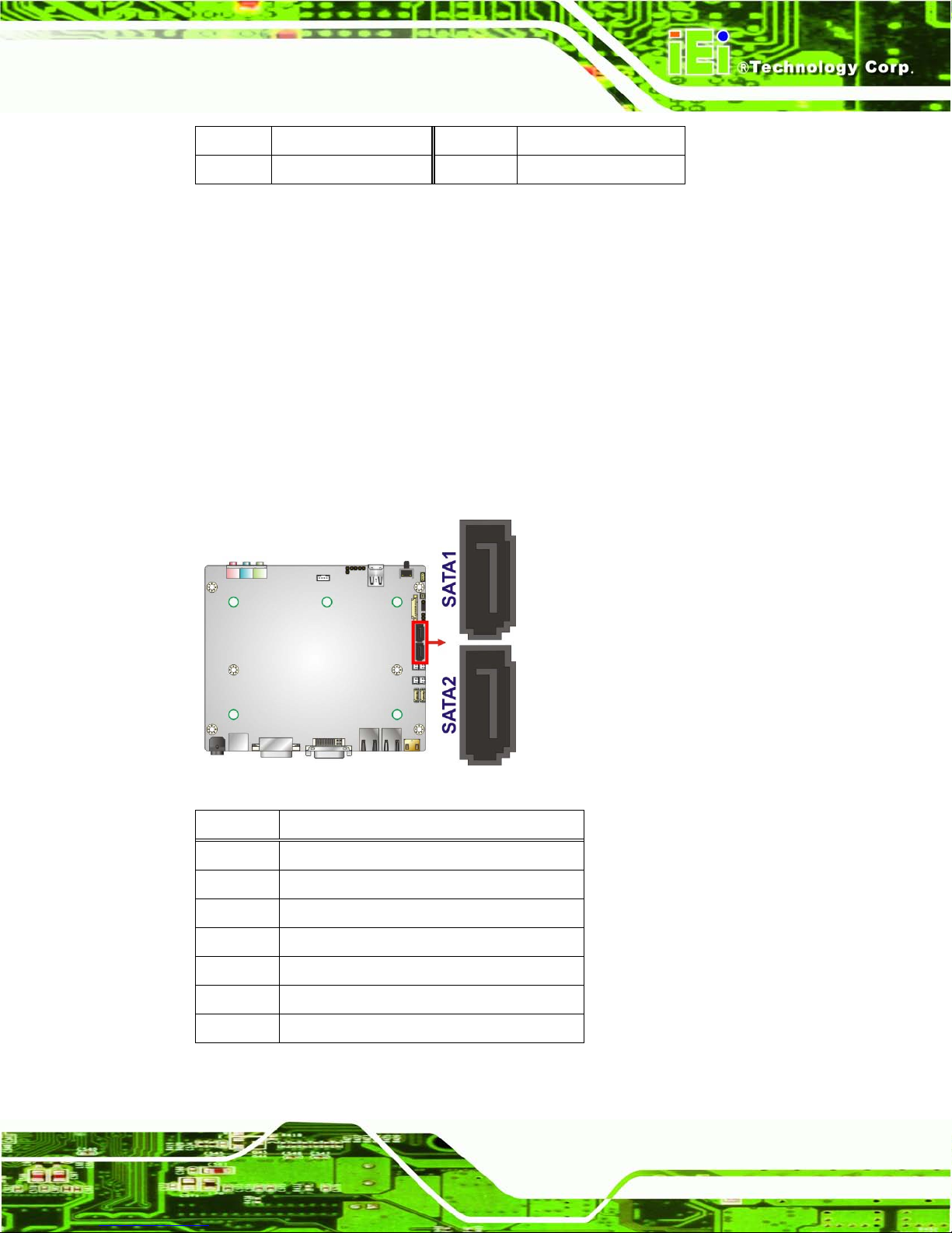
4.2.8 S AT A Dr ive Connectors
CN Label: S ATA1, S AT A2
CN T y pe:
7-pin SA TA drive connectors
CN Location: See Figure 4-10
CN Pinouts: See Table 4-10
The SATA connect ors connect to SATA hard dri ves or optical drives with data transfer
speeds as high as 3Gb/s.
Figure 4-10: SATA Drive Connector Locations
Pin Description
1 GND
2 TX+
3 TX4 GND
5 RX6 RX+
7 GND
Table 4-10: SATA Drive Connector Pinouts
Page 66

ECN-680A-H61 Embedded System
Page 52
4.2.9 S ATA Power Connectors
CN Label: CN1, CN2
CN T y pe:
2-pin wafer
CN Location: See Figure 4-11
CN Pinouts: See Table 4-11
Use the SATA Power Connector to connect to SATA device power connections.
Figure 4-11: SATA Power Connector Locations
Pin Description
1 +V5S
2 GND
Table 4-11: SATA Power Connector Pinouts
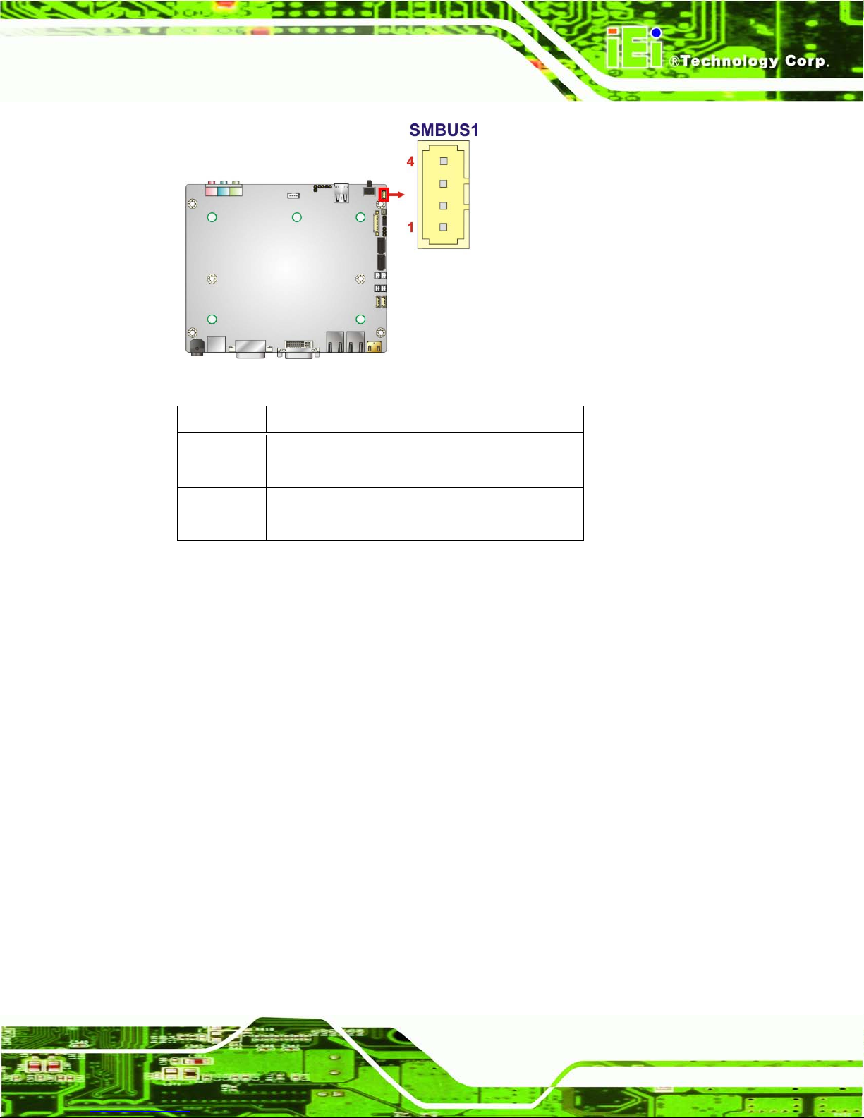
4.2.10 S MBu s Connector
CN Label: SMBUS1
CN T y pe:
4-pin wafer
CN Location: See Figure 4-12
CN Pinouts: See Table 4-12
The SMBus (System Management Bus) connector provides low-speed system
management communications.
Page 67
ECN-680A-H61 Embedded System
Page 53
Figure 4-12: SMBus Connector Location
Pin Description
1 GND
2 SMB_DATA
3 SMB_CLK_A
4 +V5S
Table 4-12: SMBus Connector Pinouts
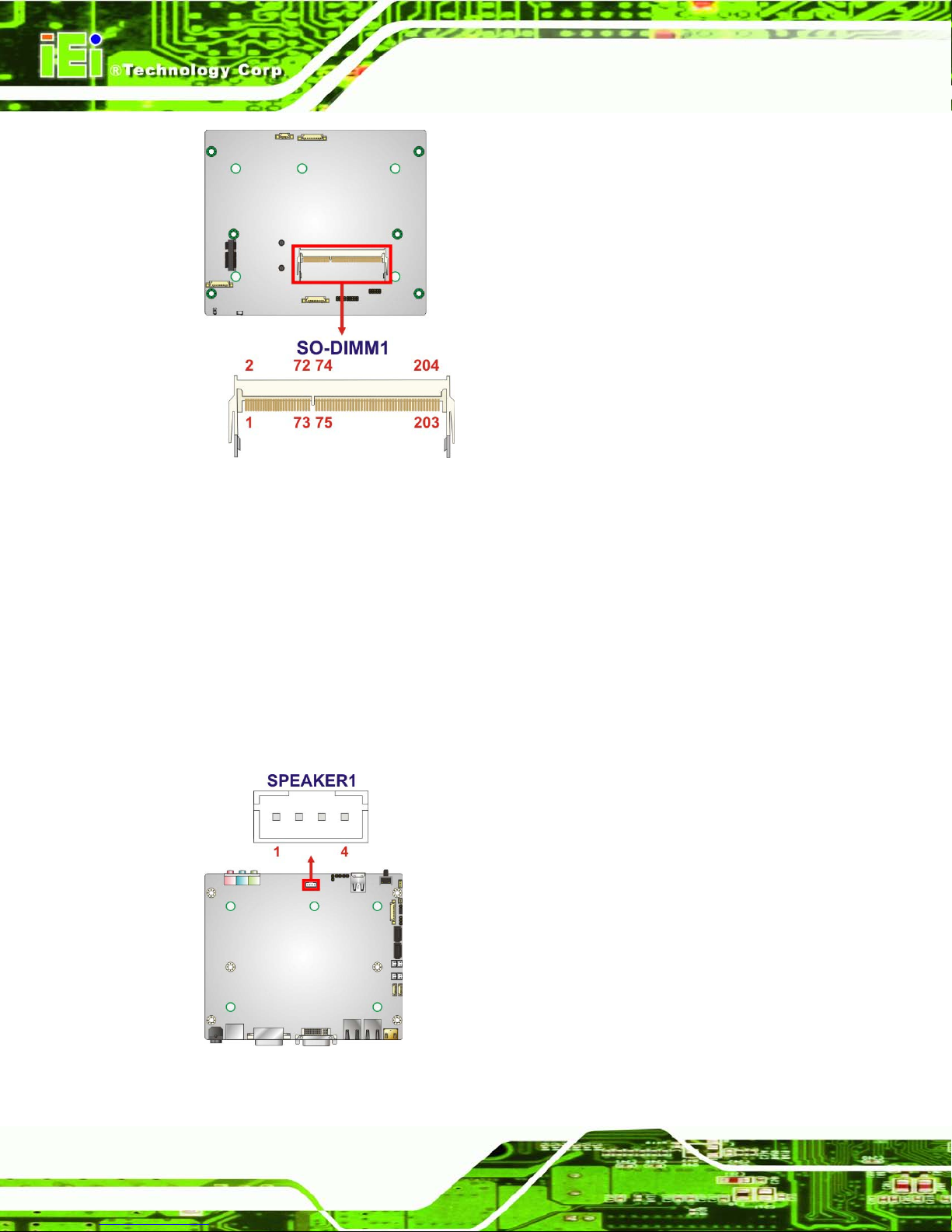
4.2.11 SO-DIMM Connector
CN Label: SO-DIMM1
CN T y pe:
204-pin DDR3 SO-DIMM connector
CN Location: See Figure 4-13
The SO-DIMM connector is for installing memory on the system.
Page 68
ECN-680A-H61 Embedded System
Page 54
Figure 4-13: SO-DIMM Connector Locations
4.2.12 Speaker Connector
CN Label: SPEAKER1
CN T y pe:
4-pin wafer
CN Location: See Figure 4-14
CN Pinouts: See Table 4-13
Use the speaker connector to connect speakers to the system.
Figure 4-14: SPDIF Connector Loc ation
Page 69
ECN-680A-H61 Embedded System
Page 55
PIN DESCRIPTION
1 SPK_L
2 GND
3 GND
4 SPK_R
Table 4-13: SPDIF Connector Pinouts
4.2.13 SPI Flas h Connector
CN Label: JSPI2
CN T y pe:
6-pin wafer
CN Location: See Figure 4-15
CN Pinouts: See Table 4-14
The SPI Flash connector is used to flash the BIOS.
Figure 4-15: SPI Flash Connector Location
Pin Description
1
+SPI_VCC
2
SPI_CS0#_CN
3
SPI_SO0_CN
4
SPI_CLK0_CN
5
SPI_SI0_CN
6
GND
Table 4-14: SPI Flash Connector Pinouts
Page 70
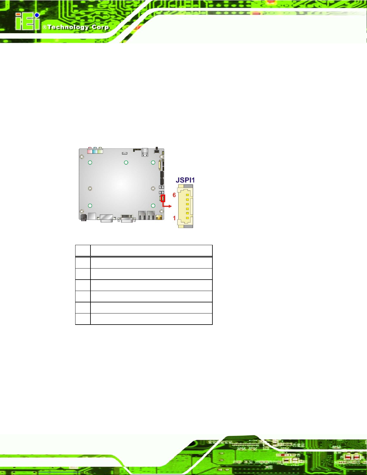
ECN-680A-H61 Embedded System
Page 56
4.2.14 SPI Flas h Connector (EC)
CN Label: JSPI1
CN T y pe:
6-pin wafer
CN Location: See Figure 4-16
CN Pinouts: See Table 4-15
The EC SPI Flash connector is used to flash the BIOS.
Figure 4-16: EC SPI Flash Connector Location
Pin Description
1 +V3.3A_ EC_CON
2 FSCE#_S
3 FMISO_S
4 FSCK_S
5 FMOSI_S
6 GND
Table 4-15: EC SPI Flash Connector Pinouts
4.2.15 K Type Thermocouple Connectors
CN Label: CN5, CN6
CN T y pe:
2-pin wafer
CN Location: See Figure 4-17
CN Pinouts: See Table 4-16
Page 71
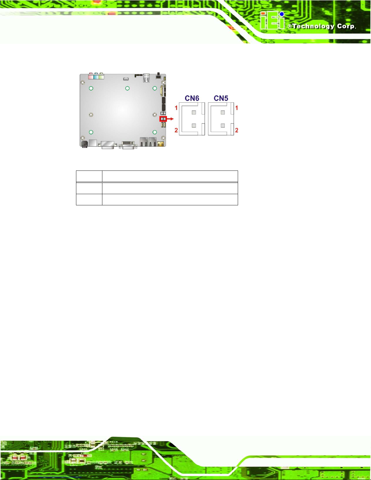
ECN-680A-H61 Embedded System
Page 57
The K type thermocouple connector connects to the K type thermocouple devices.
Figure 4-17: Type K Thermocouple Connector Locations
Pin Description
1 D12 D1+
Table 4-16: Type K Thermocouple Connector Pinouts
4.2.16 USB 2.0 Connectors
CN Label: USB0_1, USB2_3
CN T y pe:
9-pin wafer
CN Location: See Figure 4-18
CN Pinouts: See Table 4-17
The USB header can connect to two USB devices.
Page 72
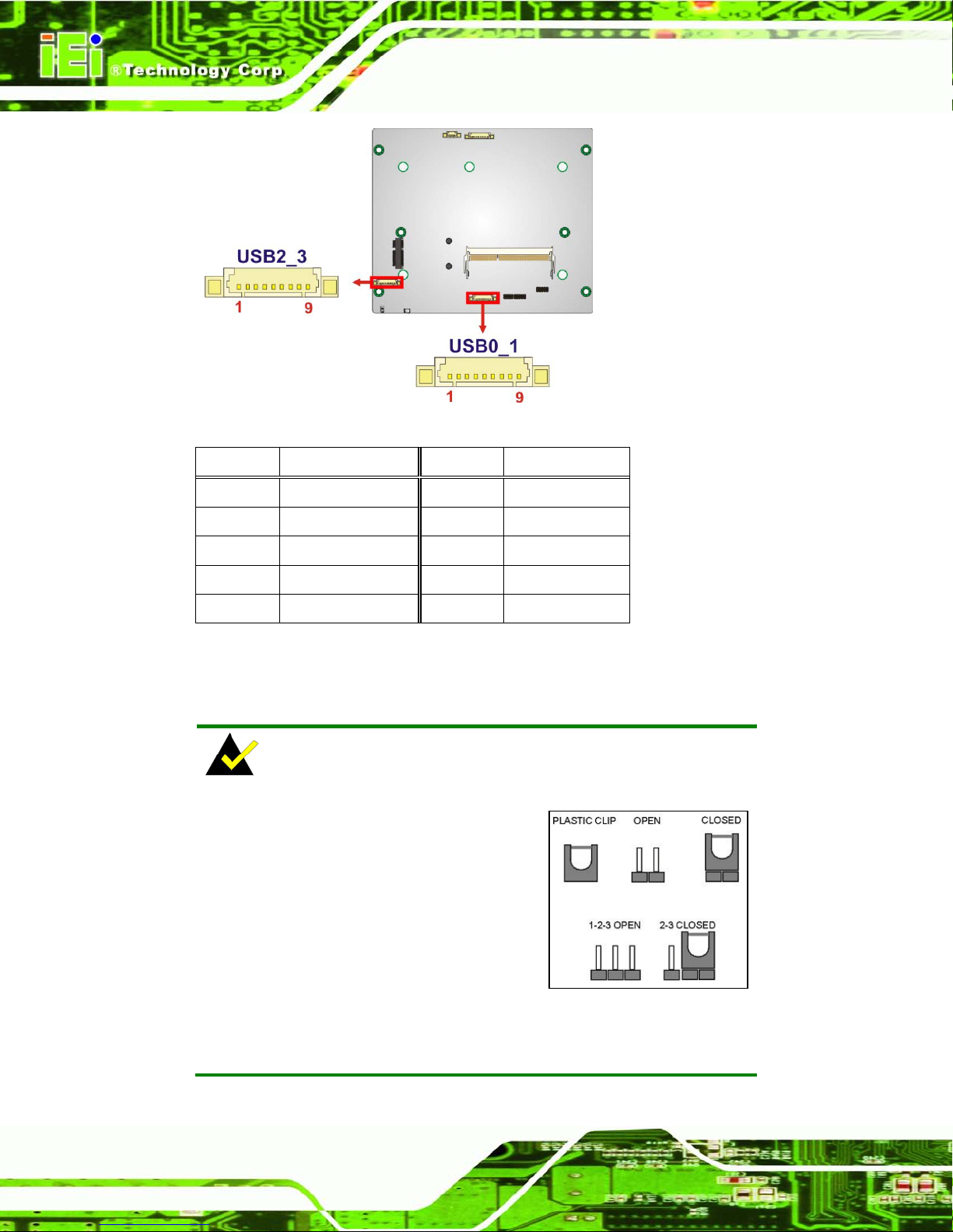
ECN-680A-H61 Embedded System
Page 58
Figure 4-18: USB Connector Locations
Pin Description Pin Description
1 VCC_USB 2 -DATA
3 +DATA 4 GND
5 NC 6 VCC_USB
7 -DATA1 8 +DATA
9 GND
Table 4-17: USB Port Connector Pinouts
4.3 Jumper Settings
NOTE:
A jumper is a metal brid ge that is used
to close an electrical circuit. It consists
of two metal pins and a small m etal cl ip
(often protected b y a plastic cover) th at
slides over the pins to connect them.
To CLOSE/SHORT a jumper means
connecting the pins of the jumper with
the plastic clip and to OP EN a jum per m eans rem oving the p lastic c lip
from a jumper.
Page 73
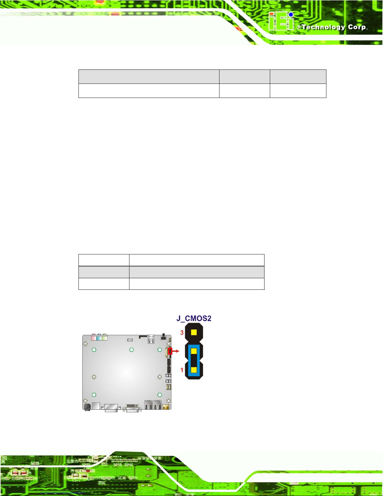
ECN-680A-H61 Embedded System
Page 59
The jumpers on the ECN-680A-H61 are listed in Table 4-18.
Description Label Type
Clear CMOS J_CMOS2 3-pin header
Table 4-18: Jumpers
4.3.1 Cle ar CMOS
Jumper Lab el: J _CMOS2
Jumper Type:
3-pin header
Jumper Settings : See Table 4-19
Jumper Location: See Figure 4-19
If the ECN-680A-H61 fails to boot due to improper BIOS setti ngs , th e c lear C MO S j um per
clears the CMOS data and resets the system BIOS information. To do this, use the jumper
cap to close pins 2 and 3 for a f ew seconds then reinstall th e jumper clip back to pins 1
and 2. The clear CMOS jumper settings are shown in Table 4-19.
Pin Description
Short 1-2 Keep CMOS Setup (Default)
Short 2-3 Clear CMOS Setup
Table 4-19: Clear CMOS Jumper Settings
Figure 4-19: Clear CMOS Jumper Locatio n
Page 74

ECN-680A-H61 Embedded System
Page 60
Chapter
5
5 BIOS
Page 75

ECN-680A-H61 Embedded System
Page 61
5.1 Introduction
The BIOS is programmed onto the BIOS chip. The BIOS setup program allows changes to
certain system settings. This chapter outlines the options that can be changed.
5.1.1 Starting Setup
The AMI BIOS is activated when the c omputer is turned on. The setup program can be
activated in one of two ways.
1. Press the D
ELETE key as soon as the system is turned on or
2. Press the D
ELETE key when the “Press Del to enter SETUP” message
appears on the screen. 0.
If the message disappears before the D
ELETE key is pressed, restart the computer and try
again.
5.1.2 Using Setup
Use the arrow keys to highlight items, press ENTER to select, use the PageUp and
PageDown keys to c hange entries, press F1 for help and press E
SC to quit. Navigation
keys are shown in.
Key Function
Up arrow Move to previous item
Down arrow Move to next item
Left arrow Move to the item on the left hand side
Right arrow Move to the item on the right hand side
Esc key Main Menu – Quit and not save changes into CMOS
Status Page Setup Menu and Option Page Setup Menu -Exit current page and return to Main Menu
F1 key General help, only for St atus Page Setup Menu and Option
Page Setup Menu
F2 key Load previous values.
F3 key Load optimized defaults
Page 76

ECN-680A-H61 Embedded System
Page 62
Key Function
F4 key Save all the CMOS changes
Table 5-1: BIOS Navigation Keys
5.1.3 Getting Help
When F1 is pressed a small help w indow describi ng the appropr iate keys to use and the
possible selections for the highlighted item appears. To exit the Help Window press E
SC or
the F1 key again.
5.1.4 Unable to Reboot after Configuration Changes
If the computer cannot boot after changes to the syst em configuration is made, CMOS
defaults. Use the jumper described in Chapter 5.
5.1.5 BIOS Men u Bar
The menu bar on top of the BIOS screen has the following main items:
Main – Changes the basic system configuration.
Advanced – Changes the advanced system settings.
Chipset – Changes the chipset settings.
Boot – Changes the sy stem boot configuration.
Security – Sets User and Supervisor Passwords.
Save & Exit – Selects exit options and loads default settings
The following sections c ompletely describe the conf iguration options found i n the menu
items at the top of the BIOS screen and listed above.
Page 77

ECN-680A-H61 Embedded System
Page 63
5.2 Ma in
The Main BIOS menu (366HBIOS Menu 1) appears when the BIOS Setup program is entered.
The Main menu gives an overview of the basic system information.
Aptio Setup Utility – Copyright (C) 2011 American Megatrends, Inc.
Main
Advanced
Chipset
Boot
Security
Save & Exit
BIOS Information
BIOS Vendor American Megatrends
Core Version 4.6.4.0
Compliency UEFI 2.0
Project Version SE08AR16.ROM
Build Date 08/23/2012 15:44:51
iWDD Vendor ICP
iWDD Version SE08ER13.bin
Memory Information
Total Memory 2048 MB (DDR3 1333)
System Date [Fri 08/24/2012]
System Time [14:20:27]
Access Level Administrator
Set the Time. Use Tab to
switch between Time
elements.
----------------------
: Select Screen
↑ ↓: Select Item
Enter Select
F1 General Help
F2 Previous Values
F3 Optimized Defaults
F4 Save
ESC Exit
Version 2.14.1219. Copyright (C) 2011 American Megatrends, Inc.
BIOS Menu 1: Main
BIOS Information
The BIOS Information lists a brief summary of the BIOS. The fields in BIOS Information
cannot be changed. The items shown in the system overview include:
BIOS Vendor: Installed BIOS vendor
Core Version: Current BIOS version
Compliency: Current compliant version
Project Version: the board version
Build Date: Date the current BIOS version was made
iWDD Vendor
The iWDD Vendor displays the installed iWDD vendor. The fields in iWDD
Vendor cannot be changed.
Page 78

ECN-680A-H61 Embedded System
Page 64
iWDD Ve rs io n
The iWDD Version displays the current iWDD version. The fields in iWDD
Version cannot be changed.
Memory Information
The Memory Information lists a bri ef summary of the on-board memor y. T he fields in
Memory Information cannot be changed.
Total Mem or y: Displa ys the auto-detected system memory size and t ype.
The System Overview field also has two user configurable fields:
Syste m Date [xx/xx/xx]
Use the System Date opti on to set the s ystem date. Manuall y enter the da y, month and
year.
Syste m Time [xx:xx:xx]
Use the System Time option to set the system time. Manu ally enter the hours, m inutes
and seconds.
5.3 Advanced
Use the Advanced m enu (367HBIOS Menu 2) to configure the CPU and peripheral devices
through the following sub-menus:
WARNING!
Setting the wrong values in the sections below m ay cause the s ystem
to malfunction. Mak e sure that the settings m ade are compatible with
the hardware.
Page 79

ECN-680A-H61 Embedded System
Page 65
Aptio Setup Utility – Copyright (C) 2011 American Megatrends, Inc.
Main
Advanced
Chipset
Boot
Security
Save & Exit
> ACPI Settings
> RTC Wake Settings
> Trusted Computing
> CPU Configuration
> SATA Configuration
> USB Configuration
> F81866 Super IO Configuration
> H/M Monitor
> Serial Port Console Redirection
> iEi Feature
System ACPI Parameters
----------------------
: Select Screen
↑ ↓: Select Item
Enter Select
F1 General Help
F2 Previous Values
F3 Optimized
Defaults
F4 Save
ESC Exit
Version 2.14.1219. Copyright (C) 2011 American Megatrends, Inc.
BIOS Menu 2: Advanced
5.3.1 ACPI Configuration
The ACPI Configuration menu (368HBIOS Menu 3) configures the A dvanced Configuration
and Power Interface (ACPI) options.
Aptio Setup Utility – Copyright (C) 2011 American Megatrends, Inc.
Advanced
ACPI Sleep State [S1 (CPU Stop Clock)]
Select the highest ACPI
sleep state the system
will enter when the
SUSPEND button is
pressed.
----------------------
: Select Screen
↑ ↓: Select Item
Enter Select
F1 General Help
F2 Previous Values
F3 Optimized
Defaults
F4 Save
ESC Exit
Version 2.14.1219. Copyright (C) 2011 American Megatrends, Inc.
BIOS Menu 3: ACPI Configuration
Page 80
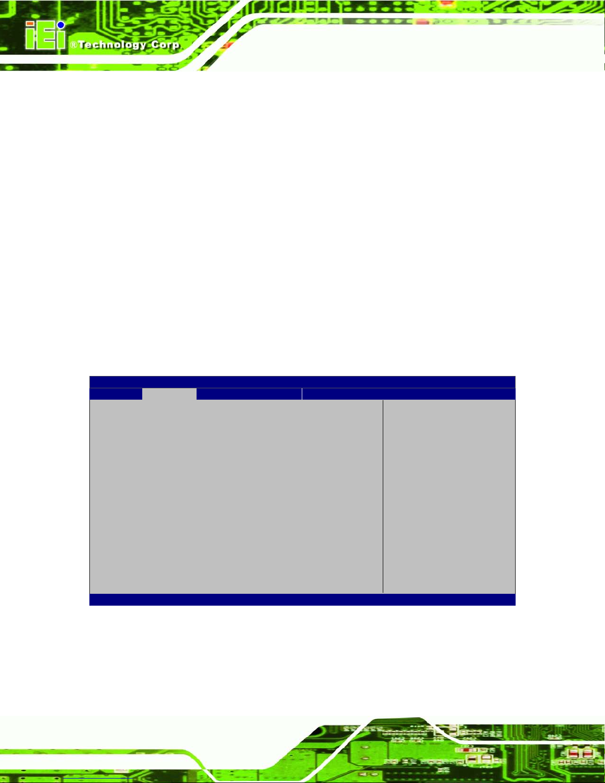
ECN-680A-H61 Embedded System
Page 66
ACPI Sleep State [S1 (CPU Stop Clock)]
Use the ACPI Sleep State option to specify the slee p state the system enters when it is
not being used.
S1 (
CPU Stop
Clock)
DEFAULT
The system enters S1 (POS) sleep state. The
system appears off. The CPU is stopped; RAM is
refreshed; the s ystem is running in a low power
mode.
S
3 (Suspend to
RAM)
The caches are flushed and the C PU is pow ered
off. Power to the RAM is maintained. The
computer returns slower to a working state, but
more power is saved.
5.3.2 RTC Wake Settings
The RTC Wake Settings menu (BIOS Menu 4) configures RTC wake event.
Aptio Setup Utility – Copyright (C) 2011 American Megatrends, Inc.
Advanced
Wake system with Fixed Time [Disabled]
Enable or disable System
wake on alarm event. When
enabled, System will
wake on the date:
hr::min::sec specified
----------------------
: Select Screen
↑ ↓: Select Item
Enter Select
F1 General Help
F2 Previous Values
F3 Optimized Defaults
F4 Save
ESC Exit
Version 2.14.1219. Copyright (C) 2011 American Megatrends, Inc.
BIOS Menu 4: RTC Wake Settings
Wake s ystem with Fixed Time [Disabled]
Use the Wake system w ith Fixed Time option to enable or disable the s ystem wak e on
alarm event.
Page 81

ECN-680A-H61 Embedded System
Page 67
Disabled D
EFAULT
The real time clock (RTC) cannot generate a w ake
event
Enabled
If selected, the Wake up every da y option appears
allowing you to enable to disable the system to wake
every day at the specified time. Besides, the
following options appear with values that can be
selected:
Wake up date
Wake up hour
Wake up minute
Wake up second
After setting the alarm, the computer turns itself on
from a suspend state when the alarm goes off.
5.3.3 Trusted Computing
Use the Trusted Computing menu (BIOS Menu 5) to configure settings related to the
Trusted Computing Group (TCG) Trusted Platform Module (TPM).
Aptio Setup Utility – Copyright (C) 2011 American Megatrends, Inc.
Advanced
TPM Configuration
TPM SUPPORT [Disable]
Current TPM Status Information
TPM SUPPORT OFF
Enables or Disables TPM
support. O.S. will not
show TPM. Reset of
platform is required.
----------------------
: Select Screen
↑ ↓: Select Item
Enter Select
+/=” Change Opt.
F1 General Help
F2 Previous Values
F3 Optimized Defaults
F4 Save & Exit
ESC Exit
Version 2.14.1219. Copyright (C) 2011 American Megatrends, Inc.
BIOS Menu 5: TPM Configuration
Page 82
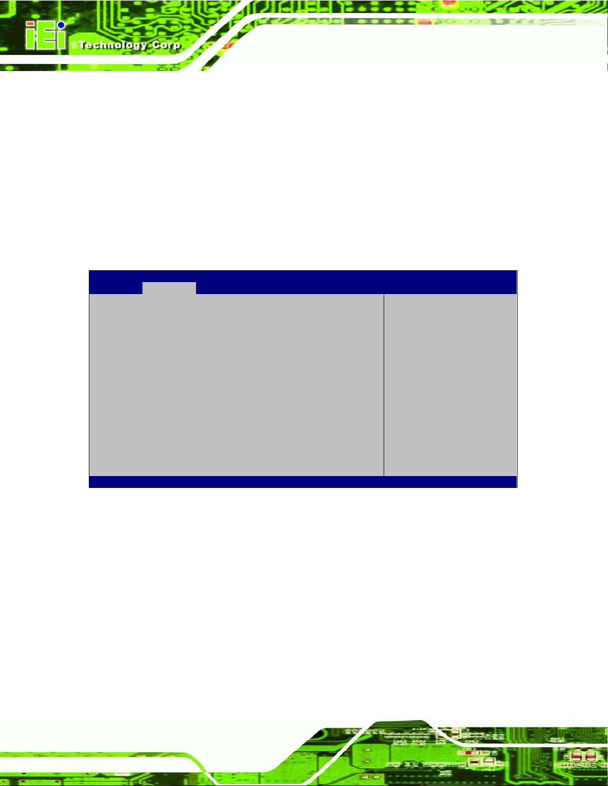
ECN-680A-H61 Embedded System
Page 68
TPM Support [Disable]
Use the TPM Support option to configure support for the TPM.
Disable DEFAULT
TPM support is disabled.
Enable
TPM support is enabled.
5.3.4 CPU Configuration
Use the CPU Configuration menu (BIOS Menu 6) to enter the CPU Information
submenu or enable Intel Virtualization Technology.
Aptio Setup Utility – Copyright (C) 2011 American Megatrends, Inc.
Advanced
CPU Configuration
> CPU Information
Hyper-threading [Enabled]
Intel Virtualization Technology [Enabled]
Socket specific CPU
Information
----------------------
: Select Screen
↑ ↓: Select Item
Enter Select
+/-: Change Opt.
F1: General Help
F2: Previous Values
F3: Optimized Defaults
F4: Save & Exit
ESC: Exit
Version 2.14.1219. Copyright (C) 2011 American Megatrends, Inc.
BIOS Menu 6: CPU Configuration
Hyper-threading [Enabled]
Use the Hyper-threading function to enable or disable the CPU hyper threading function.
Disabled
Disables the use of hyper-threading technology
Enabled DEFAULT
Enables the use of hyper-threading technology
Page 83
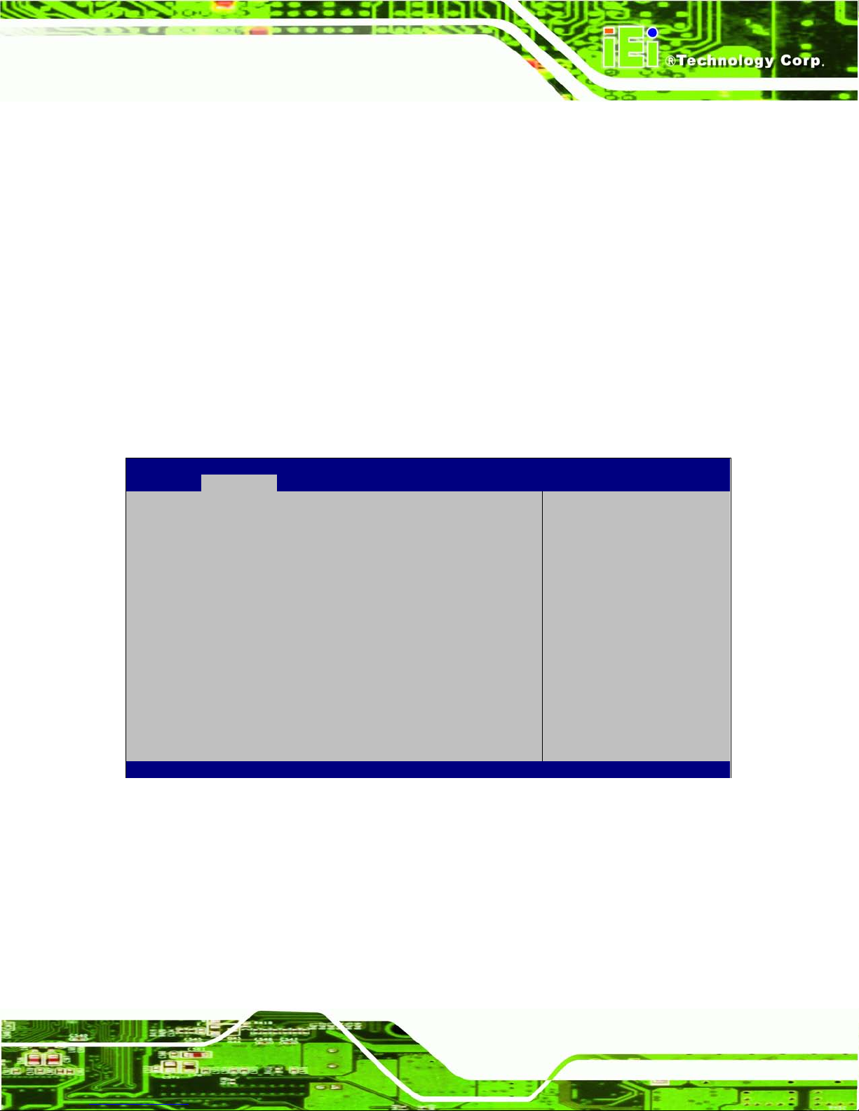
ECN-680A-H61 Embedded System
Page 69
Intel Virtualization Technology [Enabled]
Use the Intel Virtualization Technology option to enable or disable virtualization on the
system. When combined with thir d party software, Intel Virtualization technolog y allows
several OSs to run on the same system at the same time.
Disabled
Disables Intel Virtualization
Technology.
Enabled DEFAULT
Enables Intel Virtualization Technology.
5.3.4.1 CPU Information
Use the CPU Information s ubmenu (BIOS Menu 7) to view detailed CPU s pecifications
and configure the CPU.
Aptio Setup Utility – Copyright (C) 2011 American Megatrends, Inc.
Advanced
CPU Information
Intel(R) Core(TM) i3-2100T CPU @ 2.50GHz
CPU Signature 206a7
Microcode Patch 1b
Max CPU Speed 2500 MHz
Min CPU Speed 1600 MHz
Processor Cores 2
Intel HT Technology Supported
Intel VT-x Technology Supported
Intel SMX Technology Not Supported
L1 Data Cache 32 kB x 2
L1 Code Cache 32 kB x 2
L2 Cache 256 kB x 2
L3 Cache 3072 kB
----------------------
: Select Screen
↑ ↓: Select Item
Enter Select
+/-: Change Opt.
F1: General Help
F2: Previous Values
F3: Optimized Defaults
F4: Save & Exit
ESC: Exit
Version 2.14.1219. Copyright (C) 2011 American Megatrends, Inc.
BIOS Menu 7: CPU Configuration
The CPU Configuration menu (BIOS Menu 7) lists the following CPU details:
Processor Type: Lists the brand name of the CPU being used
CPU Signature: Lists the CPU signature value.
Microcode Patch: Lists the microcode patch being used.
Max CPU Speed: Lists the maximum CPU processing speed.
Min CPU Speed: Lists the minimum CPU processing speed.
Page 84
ECN-680A-H61 Embedded System
Page 70
Processor Cores: Lists the number of the processor core
Intel HT Technology: Indicates if Intel HT Technology is supported by the
CPU.
Intel VT-x Technology: Indicates if Intel VT-x Technology is supported by the
CPU.
Intel SMX Technology: Indicates if Intel SMX Technology is supported by the
CPU.
L1 Data Cache: Lists the amount of data storage space on the L1 cache.
L1 Code Cache: Lists the amount of code storage space on the L1 cache.
L2 Cache: Lists the amount of storage space on the L2 cache.
L3 Cache: Lists the amount of storage space on the L3 cache.
5.3.5 S ATA Configuration
Use the SATA Configuration menu (371HBIOS Menu 8) to change and/or set the
configuration of the SATA devices installed in the system.
Aptio Setup Utility – Copyright (C) 2011 American Megatrends, Inc.
Advanced
SATA Configuration
SATA Mode [IDE Mode]
Serial-ATA Controller 0 [Compatible]
SATA Port1 SAMSUNG SSD UM (8.0GB)
SATA Port2 Not Present
(1) IDE Mode. (2) AHCI
Mode.
---------------------
: Select Screen
↑ ↓: Select Item
Enter Select
F1 General Help
F2 Previous Values
F3 Optimized
Defaults
F4 Save
ESC Exit
Version 2.14.1219. Copyright (C) 2011 American Megatrends, Inc.
BIOS Menu 8: IDE Configuration
SATA Mode [IDE Mode]
Use the SATA Mode option to configure SATA devices as normal IDE devices.
IDE Mode DEFAULT
Configures SATA devices as normal IDE device.
Page 85
ECN-680A-H61 Embedded System
Page 71
Serial-ATA Controller 0 [Compatible]
Use the Serial-ATA Controller option to configure the Serial-ATA control ler mode when
the SATA mode is set to IDE Mode.
Enhanced
Configures the Serial-ATA controller to be in enhanced
mode. In this mode, IDE channels and SATA channels
are separated. Some legacy OS do not support this
mode.
Compatible DEFAULT
Configures the Serial-ATA controller to be in compatible
mode. In this mode, a SATA channel will replace one of
the IDE channels.
5.3.6 USB Configuration
Use the USB Configuration menu (372HBIOS Menu 9) to read USB configuration infor mation
and configure the USB settings.
Aptio Setup Utility – Copyright (C) 2011 American Megatrends, Inc.
Advanced
USB Configuration
USB Devices:
2 Hubs
Legacy USB Support [Enabled]
Enables Legacy USB
support. AUTO option
disables legacy support
if no USB devices are
connected. DISABLE
option will keep USB
devices available only
for EFI applications.
---------------------
: Select Screen
↑ ↓: Select Item
Enter Select
F1 General Help
F2 Previous Values
F3 Optimized
Defaults
F4 Save
ESC Exit
Version 2.14.1219. Copyright (C) 2011 American Megatrends, Inc.
BIOS Menu 9: USB Configuration
Page 86
ECN-680A-H61 Embedded System
Page 72
USB Devices
The USB Devices Enabled field lists the USB devices that are enabled on the system
Legacy USB Support [Enabled]
Use the Legacy USB Support BIOS option to enable USB mouse and U SB keyboard
support. Normally if this option is not enabled, any attached USB mouse or USB keyboard
does not become available until a USB compatible operating system is fully booted with all
USB drivers loaded. When this option is enabled, any attached USB mouse or USB
keyboard can control the system even when there is no USB driver loaded onto the
system.
Disabled
Legacy USB support disabled
Enabled DEFAULT
Legacy USB support enabled
Auto
Legacy USB support disa bled if no USB de vices are
connected
5.3.7 F81866 Super IO Configuration
Use the F81866 Super IO Configuration menu (373HBIOS Menu 10) to set or change the
configurations for the FDD controllers, parallel ports and serial ports.
Aptio Setup Utility – Copyright (C) 2011 American Megatrends, Inc.
Advanced
F81866 Super IO Configuration
F81866 Super IO Chip F81866
> Serial Port 1 Configuration
> Serial Port 2 Configuration
> Serial Port 3 Configuration
> Serial Port 4 Configuration
Set Parameters of Serial
Port 1 (COMA)
---------------------
: Select Screen
↑ ↓: Select Item
Enter Select
F1 General Help
F2 Previous Values
F3 Optimized
Defaults
F4 Save
ESC Exit
Version 2.14.1219. Copyright (C) 2011 American Megatrends, Inc.
BIOS Menu 10: Super IO Configuration
Page 87
ECN-680A-H61 Embedded System
Page 73
5.3.7.1 Serial P ort n Configuration
Use the Serial Port n Configuration menu (374HBIOS Menu 11) to configure the serial port n.
Aptio Setup Utility – Copyright (C) 2011 American Megatrends, Inc.
Advanced
Serial Port 0 Configuration
Serial Port [Enabled]
Device Settings IO=3F8h; IRQ=4
Change Settings [Auto]
Enable or Disable Serial
Port (COM)
---------------------
: Select Screen
↑ ↓: Select Item
Enter Select
F1 General Help
F2 Previous Values
F3 Optimized
Defaults
F4 Save
ESC Exit
Version 2.14.1219. Copyright (C) 2011 American Megatrends, Inc.
BIOS Menu 11: Serial Port n Configuration Menu
5.3.7.1.1 Serial Port 1 Configuration
Serial Po rt [Enabled]
Use the Serial Port option to enable or disable the serial port.
Disabled
Disable the serial port
Enabled DEFAULT
Enable the serial port
Change Settings [Auto]
Use the Change Settings option to c hange the serial port IO port address and interrupt
address.
Auto DEFAULT
The serial port IO port address and interrupt address
are automatically detected.
IO=3F8h;
IRQ=4
Serial Port I/O port address is 3F8h and the interrupt
address is IRQ4
Page 88

ECN-680A-H61 Embedded System
Page 74
IO=3F8h;
IRQ=3, 4
Serial Port I/O port address is 3F8h and the interrupt
address is IRQ3, 4
IO=2F8h;
IRQ=3, 4
Serial Port I/O port address is 2F8h and the interrupt
address is IRQ3, 4
IO=3E8h;
IRQ=3, 4
Serial Port I/O port address is 3E8h and the interrupt
address is IRQ3, 4
IO=2E8h;
IRQ=3, 4
Serial Port I/O port address is 2E8h and the interrupt
address is IRQ3, 4
5.3.7.1.2 Serial Port 2 Configuration
Serial Po rt [Enabled]
Use the Serial Port option to enable or disable the serial port.
Disabled
Disable the serial port
Enabled DEFAULT
Enable the serial port
Change Settings [Auto]
Use the Change Settings option to c hange the serial port IO port address and interrupt
address.
Auto DEFAULT
The serial port IO port address and interrupt address
are automatically detected.
IO=2F8h;
IRQ=3
Serial Port I/O port address is 2F8h and the interrupt
address is IRQ3
IO=3F8h;
IRQ=3, 4
Serial Port I/O port address is 3F8h and the interrupt
address is IRQ3, 4
IO=2F8h;
IRQ=3, 4
Serial Port I/O port address is 2F8h and the interrupt
address is IRQ3, 4
IO=3E8h;
IRQ=3, 4
Serial Port I/O port address is 3E8h and the interrupt
address is IRQ3, 4
Page 89

ECN-680A-H61 Embedded System
Page 75
IO=2E8h;
IRQ=3, 4
Serial Port I/O port address is 2E8h and the interrupt
address is IRQ3, 4
5.3.7.1.3 Serial Port 3 Configuration
Serial Po rt [Enabled]
Use the Serial Port option to enable or disable the serial port.
Disabled
Disable the serial port
Enabled DEFAULT
Enable the serial port
Change Settings [Auto]
Use the Change Settings option to c hange the serial port IO port address and interrupt
address.
Auto DEFAULT
The serial port IO port address and interrupt address
are automatically detected.
IO=3E8h;
IRQ=7
Serial Port I/O port address is 3E8h and the interrupt
address is IRQ7
IO=3F8h;
IRQ=7, 10
Serial Port I/O port address is 3F8h and the interrupt
address is IRQ7, 10
IO=2F8h;
IRQ=7, 10
Serial Port I/O port address is 2F8h and the interrupt
address is IRQ7, 10
IO=3E8h;
IRQ=7, 10
Serial Port I/O port address is 3E8h and the interrupt
address is IRQ7, 10
IO=2E8h;
IRQ=7, 10
Serial Port I/O port address is 2E8h and the interrupt
address is IRQ7, 10
Page 90

ECN-680A-H61 Embedded System
Page 76
5.3.7.1.4 Serial Port 4 Configuration
Serial Po rt [Enabled]
Use the Serial Port option to enable or disable the serial port.
Disabled
Disable the serial port
Enabled DEFAULT
Enable the serial port
Change Settings [Auto ]
Use the Change Settings option to c hange the serial port IO port address and interrupt
address.
Auto DEFAULT
The serial port IO port address and interrupt address
are automatically detected.
IO=2E8h;
IRQ=10
Serial Port I/O port address is 2E8h and the interrupt
address is IRQ10
IO=3F8h;
IRQ=7, 10
Serial Port I/O port address is 3F8h and the interrupt
address is IRQ7, 10
IO=2F8h;
IRQ=7, 10
Serial Port I/O port address is 2F8h and the interrupt
address is IRQ7, 10
IO=3E8h;
IRQ=7, 10
Serial Port I/O port address is 3E8h and the interrupt
address is IRQ7, 10
IO=2E8h;
IRQ=7, 10
Serial Port I/O port address is 2E8h and the interrupt
address is IRQ7, 10
Device Mode [RS422/485]
The Device Mode shows Serial Port 4 provides RS-422/485 communications.
Page 91

ECN-680A-H61 Embedded System
Page 77
5.3.8 H/W Monitor
The H/W Monitor menu (BIOS Menu 12) shows the hardware health status.
Aptio Setup Utility – Copyright (C) 2011 American Megatrends, Inc.
Advanced
PC Health Status
CPU Temperature :+46 C
System1 Temperature :+34 C
System2 Temperature :+34 C
CPU Fan Speed :3500 RPM
Smart Fan Mode Select
---------------------
: Select Screen
↑ ↓: Select Item
Enter Select
+/-: Change Opt.
F1: General Help
F2: Previous Values
F3: Optimized Defaults
F4: Save & Exit
ESC: Exit
Version 2.14.1219. Copyright (C) 2011 American Megatrends, Inc.
BIOS Menu 12: Hardware Health Config u ration
PC Hea lth S ta tus
The following system param eters and va lues ar e show n. The s ystem par am eters that are
monitored are:
System Te mperatures:
o CPU Temperature
o System1 Temperature (CN5)
o System2 Temperature (CN6)
Fan Speeds:
o CPU Fan Speed
5.3.9 Se rial Port Console Redirection
The Serial Port Console Redirection menu (378HBIOS Menu 13) allows the console
redirection options to be configured. Console redirection allows users to maintain a
system remotely by re-directing keyboard input and text output through the serial port.
Page 92

ECN-680A-H61 Embedded System
Page 78
Aptio Setup Utility – Copyright (C) 2011 American Megatrends, Inc.
Advanced
COM1
Console Redirection [Disabled]
> Console Redirection Settings
COM2
Console Redirection [Disabled]
> Console Redirection Settings
COM3
Console Redirection [Disabled]
> Console Redirection Settings
Console Redirection
Enable or Disable.
---------------------
: Select Screen
↑ ↓: Select Item
Enter Select
F1 General Help
F2 Previous Values
F3 Optimized
Defaults
F4 Save
ESC Exit
Version 2.14.1219. Copyright (C) 2011 American Megatrends, Inc.
BIOS Menu 13: Serial Port Console Redirection
Console Redirection
Use Console Redirection option to enable or disable the console redirection function.
Disabled DEFAULT
Disables the console redirection function.
Enabled
Enabled the console redirection function.
5.3.9.1 Console Redirection Settings
The Console Redirection Settings menu (379HBIOS Menu 14) allows the console redirection
options to be configured. The option is active when Console Redirection option is enabled.
Page 93

ECN-680A-H61 Embedded System
Page 79
Aptio Setup Utility – Copyright (C) 2011 American Megatrends, Inc.
Advanced
COM0
Console Redirection Settings
Terminal Type [ANSI]
Bits per second [115200]
Data Bits 8
Parity None
Stop Bits 1
Emulation: ANSI:
Extended ASCII char set.
VT100: ASCII char set.
VT100+: Extends VT100 to
support color, function
keys, etc. VT-UTF8: Uses
UTF8 encoding to map
Unicode chars onto 1 or
more bytes.
---------------------
: Select Screen
↑ ↓: Select Item
Enter Select
F1 General Help
F2 Previous Values
F3 Optimized
Defaults
F4 Save
ESC Exit
Version 2.14.1219. Copyright (C) 2011 American Megatrends, Inc.
BIOS Menu 14: Console Redirection Settings
Termina l Ty p e [ANSI]
Use the Terminal Typ e option to specify the remote terminal type..
VT100
The target terminal type is VT100
VT100+
The target terminal type is VT100+
VT-UTF8
The target terminal type is VT-UTF8
ANSI DEFAULT
The target terminal type is ANSI
Bits per second [115200]
Use the Bits per second option to specify the transmission speed of the serial port.
9600
The transmission speed is 9600
19200
The transmission speed is 19200
57600
The transmission speed is 57600
Page 94

ECN-680A-H61 Embedded System
Page 80
115200 DEFAULT
The transmission speed is 115200
5.4 iEi Feature
Use the iEi Feature menu (BIOS Menu 15) to configure the auto recovery function.
Aptio Setup Utility – Copyright (C) 2011 American Megatrends, Inc.
Advanced
iEi Feature
Auto Recovery Function [Disabled]
Auto Recovery Function
Reboot and recover
system automatically
within 10 min, when OS
crashes. Please install
Auto Recovery API
service before enabling
this function
---------------------
: Select Screen
↑ ↓: Select Item
Enter Select
+/-: Change Opt.
F1: General Help
F2: Previous Values
F3: Optimized Defaults
F4: Save & Exit
ESC: Exit
Version 2.14.1219. Copyright (C) 2011 American Megatrends, Inc.
BIOS Menu 15: iEi Feature
Au to Recovery Function [Disabled]
Use the Auto Recovery Function option to enable or disable auto recovery on the
system.
Disabled DEFAULT
Auto Recovery Function support disabled
Enabled
Auto Recovery Function support enabled
Page 95

ECN-680A-H61 Embedded System
Page 81
5.5 Chipset
Use the Chipset menu (380HBIOS Menu 16) to access the Northbridge and Southbridge
configuration menus
WARNING!
Setting the wrong values for the Chipset BIOS selections in the Chipset
BIOS menu may cause the system to malfunction.
Aptio Setup Utility – Copyright (C) 2011 American Megatrends, Inc.
Main
Advanced
Chipset
Boot
Security
Save & Exit
> North Bridge
> South Bridge
> Intel IGD SWSCI OpRegion
North Bridge Parameters
---------------------
: Select Screen
↑ ↓: Select Item
Enter Select
F1 General Help
F2 Previous Values
F3 Optimized
Defaults
F4 Save
ESC Exit
Version 2.14.1219. Copyright (C) 2011 American Megatrends, Inc.
BIOS Menu 16: Chipset
Page 96
ECN-680A-H61 Embedded System
Page 82
5.5.1 Northbridge Configuration
Use the Northbridge Chipset Configuration menu (381HBIOS Menu 17) to configure the
Northbridge chipset.
Aptio Setup Utility – Copyright (C) 2011 American Megatrends, Inc.
Chipset
Memory Information
Total Memory 2048 MB (DDR3 1333)
Memory Slot 2048 MB (DDR3 1333)
VT-d [Disabled]
IGD Memory [256M]
IGD Share Memory Size
---------------------
: Select Screen
↑ ↓: Select Item
Enter Select
F1 General Help
F2 Previous Values
F3 Optimized
Defaults
F4 Save
ESC Exit
Version 2.14.1219. Copyright (C) 2011 American Megatrends, Inc.
BIOS Menu 17:Northbridge Chipset Configuration
IGD Me mo r y [256M]
Use the IGD Memory option to specify the amount of system memory that can be used by
the internal graphics device.
32 M
32 MB of memory used by internal graphics device
64 M
64 MB of memory used by internal graphics device
128 M
128 MB of memory used by internal graphics
device
256 M DEFAULT
256 MB of memory used by internal graphics
device
512 M
512 MB of memory us
ed by internal graphics
device
Page 97
ECN-680A-H61 Embedded System
Page 83
5.5.2 Southbridge Configuration
Use the Southbridge Configuration menu (382HBIOS Menu 18) to configure the Southbridge
chipset.
Aptio Setup Utility – Copyright (C) 2011 American Megatrends, Inc.
Chipset
Auto Power Button Status [Disable(ATX)]
Restore AC Power Loss [Last State]
Audio Configuration
Azalia HD Audio [Enabled]
Azalia internal HDMI codec [Enabled]
Power Saving Function [Disabled]
WIFI Support [Enabled]
Specify what state to go
to when power is
re-applied after a power
failure (G3 state).
---------------------
: Select Screen
↑ ↓: Select Item
Enter Select
F1 General Help
F2 Previous Values
F3 Optimized
Defaults
F4 Save
ESC Exit
Version 2.14.1219. Copyright (C) 2011 American Megatrends, Inc.
BIOS Menu 18:Southbridge Chipset Configuration
Restore AC Power Los s [Las t State]
Use the Restore on AC Power Loss option to specify wh at state t he s ystem returns t o if
there is a sudden loss of power to the system.
Power Off
The system remains turned off
Power On
The system turns on
Last State DEFAULT
The system returns to its p revious state. If it was on, it
turns itself on. If it was off, it remains off.
Azalia HD Audio [Enabled]
Use the Azalia HD Audio option to enable or disable the High Definition Audio controller.
Disabled
The onboard High Definition Audio controller is disabled
Page 98

ECN-680A-H61 Embedded System
Page 84
Enabled DEFAULT
The onboard High Definition Audio controller
automatically detected and enab led
Azalia internal HDMI codec [Enabled]
Use the Azalia internal H D MI codec option to enable or disable the i nter na l HD M I c odec
for High Definition Audio.
Disabled
Disables the internal HDMI codec for High Definition Audio
Enabled DEFAULT
Enables the internal HDMI codec for High Definition Audio
Power Saving Function [Dis abled]
Use the Power Sav ing Function BIOS option to en able or reduce p o wer cons um ption in
the S5 state. When enabled, the system can only be powered-up using the power button.
Disabled DEFAULT
Power saving function support disabled
Enabled
Power saving function support enabled
WIFI Support [Enabled]
Use the WIFI Support option to enable or disable the Wi-Fi function.
Disabled
Wi-Fi function disabled
Enabled DEFAULT
Wi-Fi function enabled
Page 99
ECN-680A-H61 Embedded System
Page 85
5.5.3 In te l IGD SWSCI OpRegion
Use the Intel IGD SWSCI OpRegion menu (383HBIOS Menu 19) to configure the video device
connected to the system.
Aptio Setup Utility – Copyright (C) 2011 American Megatrends, Inc.
Chipset
Intel IGD SWSCI OpRegion Configuration
DVMT Mode Select [DVMT Mode]
DVMT/FIXED Memory [Maximum]
IGD - Boot Type [VBIOS Default]
Select DVMT Mode used by
Internal Graphics
Device.
---------------------
: Select Screen
↑ ↓: Select Item
Enter Select
F1 General Help
F2 Previous Values
F3 Optimized
Defaults
F4 Save
ESC Exit
Version 2.14.1219. Copyright (C) 2011 American Megatrends, Inc.
BIOS Menu 19: Intel IGD SWSCI OpRegion
DVMT Mode Select [DVMT Mode]
Use the DVMT Mode Select option to select the Intel Dynamic Video Memory Technology
(DVMT) operating mode.
Fixed Mode
A fixed portion of graphics memory is reserved as
graphics memory.
DVMT Mode DEFAULT
Graphics memory is dynamically allocated according to
the system and graphics needs.
DVMT Me mo ry [Maximum]
Use the DVMT Memory option to specify the maximum am ount of memory that can be
allocated as graphics memory. Configuration options are listed below.
128 MB
256 MB
Page 100

ECN-680A-H61 Embedded System
Page 86
Maximum DEFAULT
IGD - Boot Type [VBIOS Default]
Use the IGD - Boot Type option to select t he displa y device used b y the system when it
boots. For dual display support, select “Auto.” Configuration options are listed below.
VBIOS Default
DEFAULT
DVI-I
DVI-D
HDMI
5.6 Boot
Use the Boot menu (383HBIOS Menu 20) to configure system boot options.
Aptio Setup Utility – Copyright (C) 2011 American Megatrends, Inc.
Main
Advanced
Chipset
Boot
Security
Save & Exit
Boot Configuration
Bootup NumLock State [On]
Quiet Boot [Enabled]
Option ROM Messages [Force BIOS]
Launch PXE Boot [Disabled]
UEFI Boot [Disabled]
Boot Option Priorities
Boot Option #1 [SATA PM:SAMSUNG…]
Hard Drive BBS Prioties
Select the keyboard
NumLock state
---------------------
: Select Screen
↑ ↓: Select Item
Enter Select
F1 General Help
F2 Previous Values
F3 Optimized
Defaults
F4 Save
ESC Exit
Version 2.14.1219. Copyright (C) 2011 American Megatrends, Inc.
BIOS Menu 20: Boot
Bootup NumLock State [On]
Use the Bootup NumLock State BIO S option to spec ify if the num ber lock setting m ust
be modified during boot up.
 Loading...