

Page 1

EB-5800
USER’ MANUAL
(Ver 1.0)
Page 2

1
Copyright Notice
©Copyright 2002 by ICP Electronics Inc. All Rights Reserved.
Vision: 1.0. Jan. 15. 2003.
The information in this document is subject to change without prior notice in order to
improve reliability, design and function and does not represent a commitment on the
part of the manufacturer.
In no event will the manufacturer be liable for direct, indirect, special, incidental, or
consequential damages arising out of the use or inability to use the product or
documentation, even if advised of the possibility of such damages.
This document contains proprietary information protected by cop yright. All rights are
reserved. No part of this manual ma y be reproduced b y an y mechanical, electronic, or
other means in any form without prior written permission of the manufacturer.
Trademarks
EB-5800 is a registered trademark of ICP Electronics Inc. IBM PC is a registered
trademark of International Business Machines Corporation. Intel is a registered
trademark of Intel Corporation. Other product names mentioned herein are used for
identification purposes only and may be tradema rks and/or registered trademarks of
their respective companies. If you have any questions or need other information,
please visit to our web site.
http://www.iei.com.tw
Page 3

2
Table of Contents
1. Introduction................................................................3
1.1 Checklist.......................................................................3
1.2 Features........................................................................3
1.3 Specifications ...............................................................4
1.4 Dimensions...................................................................5
2. System Setup...............................................................6
2.1 Assembly Diagram ......................................................6
2.2 Cabinet Assemble...................................................... 8
2.2.1 NOVA-7898 SBC Installation…………………….8
2.2.2 HDD Installation………………………………….9
2.2.3 Power Supply Installation……………………….10
2.2.4 LCM Installation…………………………………11
Appendix A Power Supply Specification.…………………….…12
Appendix B Cable layout Diagram………………………….13
Page 4

3
Warning: Whenever you need to take off a part for either maintenance or
upgrading purpose, you should switch off the power supply and unplug the
power cord first.
1 Introduction
The EB-5800 takes advantages of CPU board, HDD, power supply and passive
backplane for minimum size and slot plug-in connection. It is wireless, and screw less
for installation, repair part. It is an IBM PC/AT compatible computer specially
designed to meet the applications for Industrial.
1.1 Checklist
Besides the system ther e are few items in package
Item Description Qty.
1 EB-5800 User’s Manual
1
2 Power Cable
1
3 Screw Accessories
1
4 NOVA-7898 User Manual (option)
1
5 A125LCM DRIVER DISK (option)
1
6
1.2 Features
Industrial Chassis
EB-5800 is networking platform for desktop solution.
Base model equipped NOVA-7898, 3.5” HDD and ACE-816APS. There are 6
LAN port and a serial port in the front panel.
LCM model equipped with a 16x2 LCD module to display the system
information.
Full function model, having VGA, USB, PS/2 keyboard, Mouse port, Parallel
port on the rear panel
Industrial Power Supply: ACE-816APS series Power Supply
High reliability switching Power Supply with height 40.6mm only
Standard Power Supply: ACE-816APS
NOVA-7898
Support Intel Server level processor Tualatin CPU up to 1.4GHz
Support 6 LAN—Two on board, two-module slot for LM-2G, LM-102 or
LM-SSLA module.
Provide 2x DIMM memory socket to up to 512MB.
Page 5

4
1.3 Specifications
NOVA-7898
CPU Socket 370 supports Intel P3 Tualatin up to 1.4GHz.
System chipset Intel 815E-B step
Main Memory Type DIMM
DIMM 2 slot,
Max. 512MB
LAN Chip Intel 82562 and 82559 10/100Mbps
Video On-Chip Shaded Memory, DB15
Interface Serial RS232 x2
USB X2
LAN RJ45 x 2
PS/2 X1
IDE Two ATA 100 channel, 40 pin x1, 44 pin x1
FDD X1, 34 pin
Parallel port X1
IrDA X1
Power connector ATX On board on/off switch
LED
Power, HDD,
LAN On board
BIOS AWARD
Please refer the NOVA-7898 manual for detail specification
Page 6

5
1.4 Dimensions
325(W) x301 (H) x44 (D) mm.
Shown below is Full Function model, with and w/o LCM
325
3
0
0
3
0
1
4
4
Page 7

6
2 System Setup
The EB-5800 is provided complete kit for your operation. The followin g sections of
this chapter will help your installation and maintenance.
2.1 Assembly Diagram
The Rear side of EB-5800
The diagram shows the rear side of EB-5800. For maintenance, installation or
upgrade, you have to remove the back cover first by unfastening 2 screws as the
diagram shown.
Warning: Before any installation/un-installation, please notice any effects of static
electricity.
Page 8

7
The Top/Front View of EB-5800
The diagram shows the front side of EB-5800.
The diagram shows two kinds the front side of EB-5800.
With LCM and with out LCM
EB-5800LCM
EB-5800
Page 9
8
2.2 Cabinet Assemble
EB-5800 is designed for easy assemble. It is very easy to install the SBC, HDD,
Power supply and LCM. To installation shows below.
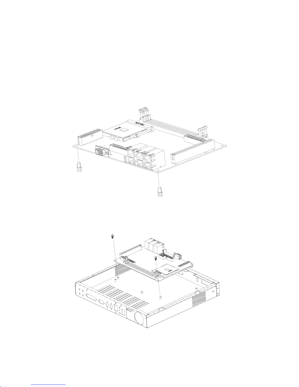
2.2.1 SBC Inst allation
To install the nova-7898 CPU Board, you have to put the plastic studs into the board
then place it into the cabinet and fasten it by two screws.
Please refer the NO VA-7898 manual for cable connecting and CPU,
Memory install.
Page 10

9
2.2.2 HDD Insta llation
To install the HDD, you have to assemble the HDD to the HDD bracket first. Then,
fasten the HDD bracket to the cabinet by four screws.
Page 11

10
2.2.3 Power Supply Installation
The standard Power Supply for EB-5800 is ACE-816APS, which is faste ned to the
power bracket with two screws, and to be installed in the cabinet by fastening three
screws as below diagram shown.
Please refer the NOVA-7898 m anual for power connectin g.
Page 12

11
2.2.4 LCM Installation
Please refer NOVA-7898 manual for connecting with A125
Page 13

12
Appendix A
ACE-816AP power supply specification
Input: 90VAC ~ 264VAC full range
OUTPUT RATING
Hold-Up time: 17ms
Efficiency: 68% type
Protection: Over Voltage/Lord and Short Circuit
TTL Power good single
Vibration: 2G
Shock: 10G 11ms for three axis.
Operation Temp: 0-50 degree C
Output Nominal Regulation Ripple/Noise Min Max
1 +3.3V
%5±
50mV 0.3A 10.0A
2 +5V
%5±
50mV 1.0A 14.0A
3 +12V
%5±
120mV 0.3A 4.2A
4 -12V
%10±
120mV 0.0A 0.3A
5 +5VSB
%5±
50mV 0A 2.0A
Page 14

13
Appendix B
Cable layout Diagram
 Loading...