

Page 1
DRPC-100 Embedded System
Page i
IEI Technology Corp.
User Manual
MODEL:
DRPC-100
Fanless Embedded System with Intel® Atom™ N2800 CPU,
DIN Rail Mounting Support, OLED Display or LED Indicators, Dual
GbE, USB, DIO, CAN-bus, Serial Ports,
9V~28V DC Power Input, RoHS Compliant
Rev. 1.01 – 22 January, 2016
Page 2

DRPC-100 Embedded System
Page ii
Date
Version
Changes
22 January, 2016
1.01
Updated the operating temperature range, packing list
and DIN rail mounting method
16 November, 2012
1.00
Initial release
Revision
Page 3

DRPC-100 Embedded System
Page iii
Copyright
COPYRIGHT NOTICE
The information in this document is subject to change without prior notice in order to
improve reliability, design and function and does not represent a commitment on the part
of the manufacturer.
In no event will the manufacturer be liable for direct, indirect, special, incidental, or
consequential damages arising out of the use or inability to use the product or
documentation, even if advised of the possibility of such damages.
This document contains proprietary information protected by copyright. All rights are
reserved. No part of this manual may be reproduced by any mechanical, electronic, or
other means in any form without prior written permission of the manufacturer.
TRADEMARKS
All registered trademarks and product names mentioned herein are used for identification
purposes only and may be trademarks and/or registered trademarks of their respective
owners.
Page 4

DRPC-100 Embedded System
Page iv
Table of Contents
1 INTRODUCTION .......................................................................................................... 1
1.1 OVERVIEW.................................................................................................................. 2
1.2 MODEL VARIATIONS ................................................................................................... 2
1.3 FEATURES ................................................................................................................... 3
1.4 CONNECTOR PANEL .................................................................................................... 4
1.4.1 Front Panel ........................................................................................................ 4
1.4.2 Top Panel ........................................................................................................... 5
1.5 LED INDICATORS (DRPC-100-CV-LED ONLY) ........................................................ 6
1.6 PROGRAMMABLE OLED DISPLAY (DRPC-100-CV-OLED ONLY) ............................ 7
1.7 TECHNICAL SPECIFICATIONS ...................................................................................... 7
1.8 DIMENSIONS ............................................................................................................... 9
2 UNPACKING ............................................................................................................... 10
2.1 ANTI-STATIC PRECAUTIONS ....................................................................................... 11
2.2 UNPACKING PRECAUTIONS ........................................................................................ 11
2.3 UNPACKING CHECKLIST ........................................................................................... 12
3 INSTALLATION ......................................................................................................... 14
3.1 INSTALLATION PRECAUTIONS ................................................................................... 15
3.1.1 High Surface Temperature ............................................................................... 15
3.2 CF CARD INSTALLATION .......................................................................................... 16
3.3 MOTHERBOARD REMOVAL ....................................................................................... 17
3.4 MSATA SSD INSTALLATION ..................................................................................... 19
3.5 JUMPER SETTINGS .................................................................................................... 21
3.5.1 Access the Jumpers .......................................................................................... 22
3.5.2 Clear CMOS Jumper ........................................................................................ 22
3.6 AT/ATX MODE SELECTION ...................................................................................... 23
3.7 MOUNTING THE SYSTEM .......................................................................................... 24
3.8 EXTERNAL PERIPHERAL INTERFACE CONNECTORS ................................................... 25
3.8.1 CAN-bus Terminal Block .................................................................................. 25
3.8.2 Digital Input/Output Terminal Block ............................................................... 26
Page 5

DRPC-100 Embedded System
Page v
3.8.3 LAN Connectors ............................................................................................... 27
3.8.4 Power Input, 3-pin Terminal Block .................................................................. 29
3.8.5 RS-232 Serial Port Connectors ........................................................................ 30
3.8.6 RS-422/485 Serial Port Connectors ................................................................. 31
3.8.7 USB Connectors ............................................................................................... 33
3.8.8 VGA Connector ................................................................................................ 34
3.9 DRIVER INSTALLATION ............................................................................................. 36
4 SYSTEM MAINTENANCE ....................................................................................... 37
4.1 SYSTEM MAINTENANCE INTRODUCTION .................................................................. 38
4.2 MOTHERBOARD REPLACEMENT ............................................................................... 38
4.3 SO-DIMM REPLACEMENT ....................................................................................... 39
5 BIOS .............................................................................................................................. 41
5.1 INTRODUCTION ......................................................................................................... 42
5.1.1 Starting Setup ................................................................................................... 42
5.1.2 Using Setup ...................................................................................................... 42
5.1.3 Getting Help ..................................................................................................... 43
5.1.4 Unable to Reboot After Configuration Changes .............................................. 43
5.1.5 BIOS Menu Bar ................................................................................................ 43
5.2 MAIN ........................................................................................................................ 44
5.3 ADVANCED ............................................................................................................... 45
5.3.1 ACPI Settings ................................................................................................... 46
5.3.2 CPU Configuration .......................................................................................... 47
5.3.3 IDE Configuration ........................................................................................... 48
5.3.4 USB Configuration ........................................................................................... 49
5.3.5 F81866 Super IO Configuration ...................................................................... 50
5.3.5.1 Serial Port n Configuration ....................................................................... 51
5.3.6 F81866 H/W Monitor ....................................................................................... 57
5.3.6.1 Smart Fan Mode Configuration ................................................................ 59
5.3.7 Serial Port Console Redirection ...................................................................... 60
5.4 CHIPSET ................................................................................................................... 62
5.4.1 Host Bridge Configuration .............................................................................. 63
5.4.1.1 Intel IGD Configuration ............................................................................ 63
5.4.2 South Bridge Configuration ............................................................................. 64
Page 6

DRPC-100 Embedded System
Page vi
5.5 BOOT ........................................................................................................................ 65
5.6 SECURITY ................................................................................................................. 67
5.7 SAVE & EXIT ............................................................................................................ 68
6 PROGRAMMABLE OLED DISPLAY (DRPC-100-CV-OLED ONLY) ................ 70
6.1 OVERVIEW................................................................................................................ 71
6.2 OLED IMAGE EDITOR .............................................................................................. 71
6.2.1 OLED Image Editor Installation ..................................................................... 71
6.2.2 Launching the OLED Image Editor ................................................................. 74
6.2.3 Function List .................................................................................................... 74
6.2.4 OLED Control .................................................................................................. 75
6.2.5 OLED Erase Page ............................................................................................ 76
6.3 DRPC100 DEMO PROGRAM ..................................................................................... 77
6.3.1 Dialog Menu .................................................................................................... 78
6.3.2 LCD Menu ........................................................................................................ 79
6.3.3 DEMO Menu .................................................................................................... 80
7 INTERFACE CONNECTORS ................................................................................... 81
7.1 PERIPHERAL INTERFACE CONNECTORS ..................................................................... 82
7.2 INTERNAL PERIPHERAL CONNECTORS ...................................................................... 83
7.2.1 Battery Connector (CN1) ................................................................................. 83
7.2.2 Burn in CAN-bus Firmware Connector (CN4) .................................................. 84
7.2.3 Burn in MCU Firmware Connector (JP5) ....................................................... 84
7.2.4 CompactFlash® Card Slot (CF1) .................................................................... 84
7.2.5 CPU Fan Connector (CPU_FAN1).................................................................. 85
7.2.6 Indicator Connector (F_PANEL1) ................................................................... 86
7.2.7 OLED/LED Signal Connector (OLED1) ......................................................... 86
7.2.8 PCIe Mini Card Slot (M_PCIE1) ..................................................................... 86
7.2.9 SATA 3Gb/s Connectors(SATA1) ...................................................................... 87
7.2.10 SATA Power Connector (SATA_PWR1) ......................................................... 88
7.2.11 SPI Flash Connector (SPI1) ........................................................................... 88
7.3 EXTERNAL INTERFACE PANEL CONNECTORS ............................................................ 88
7.3.1 CAN-bus Terminal Block (CAN1) .................................................................... 89
7.3.2 Digital I/O Terminal Block (J1) ....................................................................... 89
7.3.3 Power Input Terminal Block (DC_CN1) .......................................................... 89
Page 7

DRPC-100 Embedded System
Page vii
7.3.4 RJ-45 LAN Connectors (LAN/USB1, LAN/USB2) ........................................... 90
7.3.5 RS-232 Serial Ports (COM1/2) ........................................................................ 90
7.3.6 RS-422/485 Serial Ports (COM3/4) ................................................................. 90
7.3.7 USB 2.0 Connectors (LAN/USB1, LAN/USB2) ................................................ 91
7.3.8 VGA Connector (VGA1) ................................................................................... 91
7.4 JUMPER SETTINGS .................................................................................................... 91
7.4.1 Clear CMOS Jumper (JP1) .............................................................................. 92
7.4.2 CAN-bus 1 Long Wire Transmitting Jumper (JP3) .......................................... 92
7.4.3 CAN-bus 2 Long Wire Transmitting Jumper (JP4) .......................................... 92
A ONE KEY RECOVERY ............................................................................................. 93
A.1 ONE KEY RECOVERY INTRODUCTION ...................................................................... 94
A.1.1 System Requirement ......................................................................................... 95
A.1.2 Supported Operating System ........................................................................... 96
A.2 SETUP PROCEDURE FOR WINDOWS .......................................................................... 97
A.2.1 Hardware and BIOS Setup .............................................................................. 98
A.2.2 Create Partitions ............................................................................................. 98
A.2.3 Install Operating System, Drivers and Applications ..................................... 102
A.2.4 Build-up Recovery Partition .......................................................................... 103
A.2.5 Create Factory Default Image ....................................................................... 105
A.3 AUTO RECOVERY SETUP PROCEDURE ..................................................................... 110
A.4 SETUP PROCEDURE FOR LINUX ............................................................................... 115
A.5 RECOVERY TOOL FUNCTIONS ................................................................................. 118
A.5.1 Factory Restore ............................................................................................. 120
A.5.2 Backup System ............................................................................................... 121
A.5.3 Restore Your Last Backup .............................................................................. 122
A.5.4 Manual ........................................................................................................... 123
A.6 RESTORE SYSTEMS FROM A LINUX SERVER THROUGH LAN .................................. 123
A.6.1 Configure DHCP Server Settings .................................................................. 124
A.6.2 Configure TFTP Settings ............................................................................... 126
A.6.3 Configure One Key Recovery Server Settings ............................................... 127
A.6.4 Start the DHCP, TFTP and HTTP ................................................................. 127
A.6.5 Create Shared Directory ................................................................................ 128
A.6.6 Setup a Client System for Auto Recovery ...................................................... 129
A.7 OTHER INFORMATION ............................................................................................ 132
Page 8

DRPC-100 Embedded System
Page viii
A.7.1 Using AHCI Mode or ALi M5283 / VIA VT6421A Controller ....................... 132
A.7.2 System Memory Requirement ........................................................................ 134
B SAFETY PRECAUTIONS ....................................................................................... 135
B.1 SAFETY PRECAUTIONS ........................................................................................... 136
B.1.1 General Safety Precautions ........................................................................... 136
B.1.2 Anti-static Precautions .................................................................................. 137
B.1.3 Explanation of Graphical Symbols ................................................................ 137
B.1.4 Product Disposal ........................................................................................... 138
B.2 MAINTENANCE AND CLEANING PRECAUTIONS ...................................................... 138
B.2.1 Maintenance and Cleaning ............................................................................ 138
B.2.2 Cleaning Tools ............................................................................................... 139
C DIGITAL I/O INTERFACE ..................................................................................... 140
C.1 INTRODUCTION ...................................................................................................... 141
C.2 DIO CONNECTOR PINOUTS .................................................................................... 141
C.3 ASSEMBLY LANGUAGE SAMPLES ........................................................................... 142
C.3.1 Enable the DIO Input Function ..................................................................... 142
C.3.2 Enable the DIO Output Function .................................................................. 142
D HAZARDOUS MATERIALS DISCLOSURE ....................................................... 143
D.1 HAZARDOUS MATERIALS DISCLOSURE TABLE FOR IPB PRODUCTS CERTIFIED AS
ROHS COMPLIANT UNDER 2002/95/EC WITHOUT MERCURY ..................................... 144
Page 9

DRPC-100 Embedded System
Page ix
List of Figures
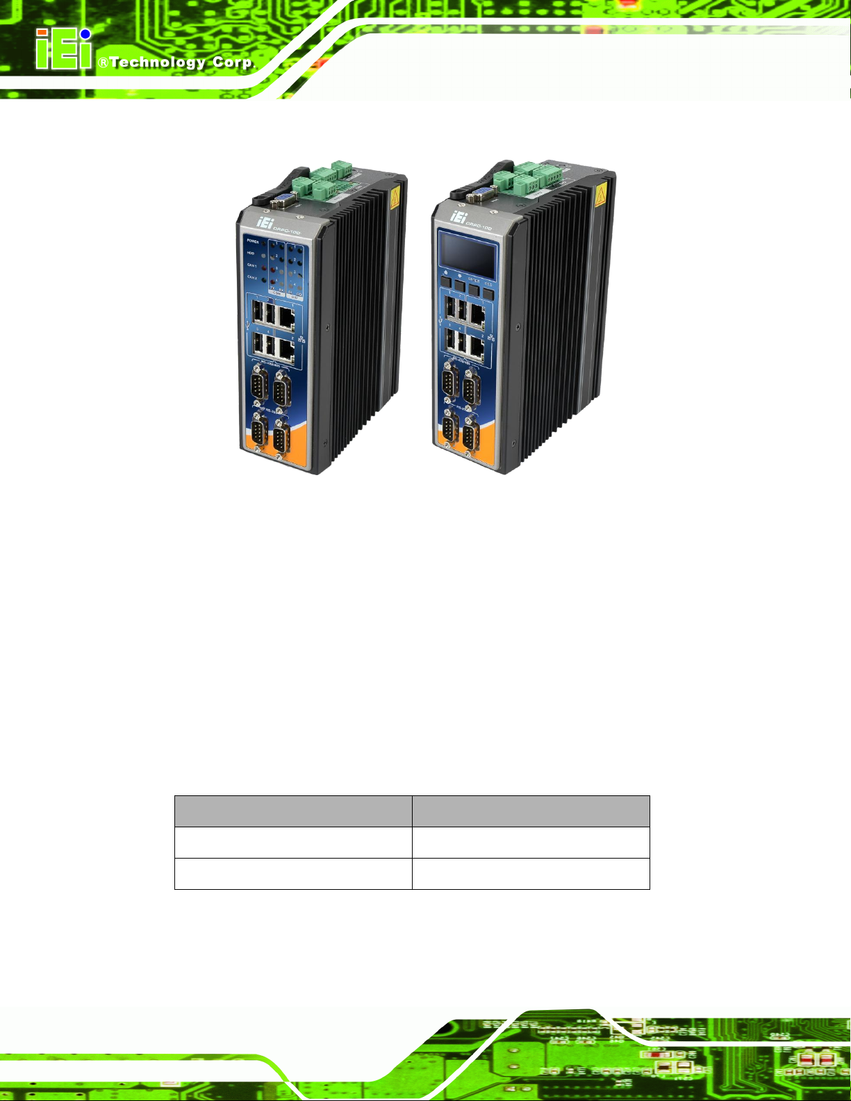
Figure 1-1: DRPC-100 ..................................................................................................................... 2
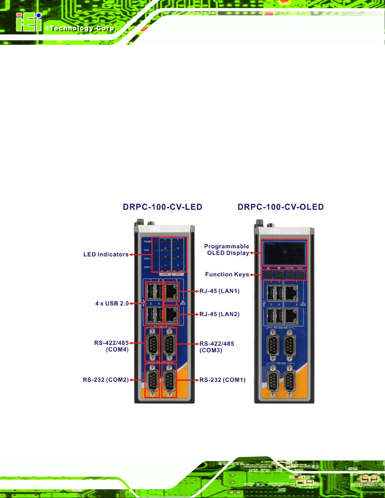
Figure 1-2: DRPC-100 Front Panel ................................................................................................ 4
Figure 1-3: DRPC-100 Top Panel ................................................................................................... 5
Figure 1-4: DRPC-100-CV-LED LED Indicators ............................................................................ 6
Figure 1-5: Physical Dimensions (millimeters) ............................................................................ 9
Figure 3-1: CF Card Slot Cover ...................................................................................................16
Figure 3-2: CF Card Installation ..................................................................................................17
Figure 3-3: Replacing the CF Card Slot Cover ..........................................................................17
Figure 3-4: Retention Screws ......................................................................................................18
Figure 3-5: Hex Nuts on the Front Panel ....................................................................................18
Figure 3-6: Hex Nuts on the Top Panel.......................................................................................19
Figure 3-7: Retention Screws on the Motherboard ...................................................................19
Figure 3-8: PCIe Mini Slot Location ............................................................................................20
Figure 3-9: Inserting the PCIe Mini Card into the Socket .........................................................20
Figure 3-10: Securing the PCIe Mini Card ..................................................................................21
Figure 3-11: Clear CMOS Jumper Location ...............................................................................23
Figure 3-12: AT/ATX Switch Location.........................................................................................23
Figure 3-13: DIN Rail Mounting Bracket .....................................................................................24
Figure 3-14: Attach the DIN Rail to the Mounting Bracket .......................................................24
Figure 3-15: Mounting the DIN Rail .............................................................................................25
Figure 3-16: CAN-bus Terminal Block Pinout Location............................................................26
Figure 3-17: DIO Terminal Block Pinout Location .....................................................................27
Figure 3-18: LAN Connection ......................................................................................................28
Figure 3-19: RJ-45 Ethernet Connector ......................................................................................28
Figure 3-20: 3-pin Power Terminal Block Pinout Location.......................................................29
Figure 3-21: RS-232 Serial Device Connector ...........................................................................30
Figure 3-22:RS-232 Serial Port Pinout Location ........................................................................31
Figure 3-23: RS-422/485 Serial Device Connector ....................................................................32
Figure 3-24: RS-422/485Serial Port Pinout Location .................................................................32
Figure 3-25: USB Device Connection .........................................................................................33
Page 10

DRPC-100 Embedded System
Page x
Figure 3-26: VGA Connector .......................................................................................................35
Figure 3-27: VGA Connector .......................................................................................................35
Figure 4-1: SO-DIMM Module Location.......................................................................................39
Figure 4-2: SO-DIMM Module Installation...................................................................................40
Figure 6-1: OLED Image Editor Setup Wizard ...........................................................................72
Figure 6-2: Select Installation Folder..........................................................................................72
Figure 6-3: Confirm Installation ..................................................................................................73
Figure 6-4: Installation Complete ................................................................................................73
Figure 6-5: OLED Image Editor ...................................................................................................74
Figure 6-6: Function List ..............................................................................................................74
Figure 6-7: OLED Control ............................................................................................................75
Figure 6-8: OLED Erase Page ......................................................................................................76
Figure 6-9: DR100 Demo Program Main Menu ..........................................................................77
Figure 6-10: Dialog Menu .............................................................................................................78
Figure 6-11: LCD Menu ................................................................................................................79
Figure 6-12: DEMO Menu .............................................................................................................80
Figure 7-1: Main Board Layout Diagram (Front Side) ...............................................................82
Figure 7-2: Main Board Layout Diagram (Solder Side) .............................................................82
Figure A-1: IEI One Key Recovery Tool Menu ...........................................................................94
Figure A-2: Launching the Recovery Tool .................................................................................99
Figure A-3: Recovery Tool Setup Menu .....................................................................................99
Figure A-4: Command Mode ......................................................................................................100
Figure A-5: Partition Creation Commands ...............................................................................101
Figure A-6: Launching the Recovery Tool ...............................................................................103
Figure A-7: Manual Recovery Environment for Windows ......................................................104
Figure A-8: Building the Recovery Partition ............................................................................104
Figure A-9: Press Any Key to Continue ...................................................................................105
Figure A-10: Press F3 to Boot into Recovery Mode ................................................................105
Figure A-11: Recovery Tool Menu ............................................................................................106
Figure A-12: About Symantec Ghost Window .........................................................................106
Figure A-13: Symantec Ghost Path ..........................................................................................107
Figure A-14: Select a Local Source Drive ................................................................................107
Figure A-15: Select a Source Partition from Basic Drive .......................................................107
Figure A-16: File Name to Copy Image to ................................................................................108
Figure A-17: Compress Image ...................................................................................................109
Page 11

DRPC-100 Embedded System
Page xi
Figure A-18: Image Creation Confirmation ..............................................................................109
Figure A-19: Image Creation Process.......................................................................................109
Figure A-20: Image Creation Complete ....................................................................................110
Figure A-21: Press Any Key to Continue .................................................................................110
Figure A-22: Auto Recovery Utility ...........................................................................................111
Figure A-23: Disable Automatically Restart .............................................................................112
Figure A-24: Launching the Recovery Tool .............................................................................113
Figure A-25: Auto Recovery Environment for Windows ........................................................113
Figure A-26: Building the Auto Recovery Partition .................................................................113
Figure A-27: Factory Default Image Confirmation ..................................................................114
Figure A-28: Image Creation Complete ....................................................................................114
Figure A-29: Press any key to continue ...................................................................................114
Figure A-30: IEI Feature .............................................................................................................115
Figure A-31: Partitions for Linux ...............................................................................................116
Figure A-32: System Configuration for Linux ..........................................................................117
Figure A-33: Access menu.lst in Linux (Text Mode) ...............................................................117
Figure A-34: Recovery Tool Menu ............................................................................................118
Figure A-35: Recovery Tool Main Menu ...................................................................................119
Figure A-36: Restore Factory Default .......................................................................................120
Figure A-37: Recovery Complete Window ...............................................................................120
Figure A-38: Backup System .....................................................................................................121
Figure A-39: System Backup Complete Window ....................................................................121
Figure A-40: Restore Backup ....................................................................................................122
Figure A-41: Restore System Backup Complete Window ......................................................122
Figure A-42: Symantec Ghost Window ....................................................................................123
Figure A-43: Disable Automatically Restart .............................................................................130
Page 12

DRPC-100 Embedded System
Page xii
List of Tables
Table 1-1: DRPC-100 Model Variations ........................................................................................ 2
Table 1-2: DRPC-100-CV-LED LED Definitions ............................................................................ 6
Table 1-3: Technical Specifications .............................................................................................. 8
Table 3-1: Jumpers .......................................................................................................................22
Table 3-2: Clear CMOS Jumper Settings ....................................................................................22
Table 3-3: CAN-bus Terminal Block Pinouts .............................................................................26
Table 3-4: DIO Terminal Block Pinouts ......................................................................................26
Table 3-5: LAN Pinouts ................................................................................................................28
Table 3-6: RJ-45 Ethernet Connector LEDs ...............................................................................29
Table 3-7: 3-pin Power Terminal Block Pinouts ........................................................................29
Table 3-8: RS-232 Serial Port Pinouts ........................................................................................31
Table 3-9: RS-422/485 Serial Port Pinouts .................................................................................32
Table 3-10: USB Port Pinouts ......................................................................................................34
Table 3-11: VGA Connector Pinouts ...........................................................................................35
Table 5-1: BIOS Navigation Keys ................................................................................................43
Table 7-1: Peripheral Interface Connectors ...............................................................................83
Table 7-2: Battery Connector (CN1) Pinouts .............................................................................83
Table 7-3: Burn in CAN-bus Firmware Connector (CN4) Pinouts .............................................84
Table 7-4: Burn in MCU Firmware (JP5) Pinouts .......................................................................84
Table 7-5: CompactFlash® Card Slot (CF1) Pinouts .................................................................85
Table 7-6: CPU Fan Connector (CPU_FAN1) Pinouts ...............................................................85
Table 7-7: Indicator Connector (F_PANEL1) Pinouts ...............................................................86
Table 7-8: OLED/LED Signal Connector (OLED1) Pinouts .......................................................86
Table 7-9: PCIe Mini Card Slot (M_PCIE1) Pinouts ...................................................................87
Table 7-10: SATA 3Gb/s Connector (SATA1) Pinouts ..............................................................87
Table 7-11: SATA Power Connector (SATA_PWR1) Pinouts ...................................................88
Table 7-12: SPI Flash Connector (SPI1) Pinouts .......................................................................88
Table 7-13: Rear Panel Connectors ............................................................................................89
Table 7-14: CAN-bus Terminal Block (CAN1) Pinouts ..............................................................89
Table 7-15: Digital I/O Terminal Block (J1) Pinouts ..................................................................89
Page 13

DRPC-100 Embedded System
Page xiii
Table 7-16: Power Input Terminal Block (DC_CN1) Pinouts ....................................................89
Table 7-17: RJ-45 LAN Connector Pinouts ................................................................................90
Table 7-18: RS-232 Serial Port Pinouts ......................................................................................90
Table 7-19: RS-422/485 Serial Port Pinouts ...............................................................................90
Table 7-20: USB 2.0 Connectors (LAN/USB1, LAN/USB2) Pinouts .........................................91
Table 7-21: VGA Connector (VGA1) Pinouts .............................................................................91
Table 7-22: Jumpers .....................................................................................................................91
Table 7-23: Clear CMOS Jumper (JP1) Settings ........................................................................92
Table 7-24: C CAN-bus 1 Long Wire Transmitting Jumper (JP3) Settings .............................92
Table 7-25: C CAN-bus 2 Long Wire Transmitting Jumper (JP4) Settings .............................92
DRPC-100
Page 14

Page 15

DRPC-100 Embedded System
Page 1
4Chapter
1
1 Introduction
Page 16
DRPC-100 Embedded System
Page 2
Figure 1-1: DRPC-100
Model No.
Indicators
DRPC-100-CV-LED-R10
LED
DRPC-100-CV-OLED-R10
OLED
Table 1-1: DRPC-100 Model Variations
1.1 Overview
The DRPC-100 fanless embedded system is powered by the Intel® Atom™ N2800
processor and uses the Intel® NM10 chipset. It is designed for harsh environment
applications and supports DIN rail mounting method.
The DRPC-100 accepts a wide range of DC power input (9V~28V), allowing it to be
powered anywhere. Four USB 2.0, two GbE, two RS-232, two RS-422/485, two CAN-bus
and one 8-bit DIO provide rich I/O options for various applications.
1.2 Model Variations
The model variations of the DRPC-100 are listed below.
Page 17

DRPC-100 Embedded System
Page 3
1.3 Features
The DRPC-100 features are listed below:
Intel® Atom™ N2800 processor
Low power consumption
Fanless design
DIN rail mounting support
Intel® GMA 3650 with 640 MHz graphics core speed supports Blu-ray 2.0,
DirectX 9, MPEG-2, H.264, C-1 and 1080p decoding
Supports 1066 MHz DDR3 SO-DIMM (up to 4 GB)
Supports one mSATA, one SATA DOM and one CompactFlash®
Wide range DC power input (9V~28V)
Extended temperature fanless design supports -25C~65C (with SSD)
One PCIe Mini card slot
Serial, CAN-bus and DIO interfaces with isolation protection
Supports two GbE, four USB 2.0, two RS-232, two RS-422/485, two CAN-bus
and one 8-bit DIO
LED indicators (DRPC-100-CV-LED only)
Programmable OLED display (DRPC-100-CV-OLED only)
RoHS compliant
Page 18
DRPC-100 Embedded System
Page 4
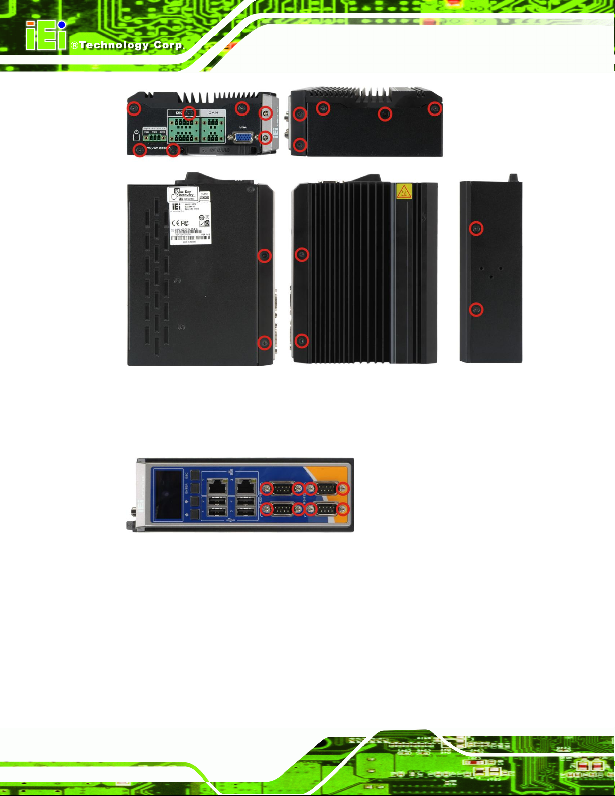
Figure 1-2: DRPC-100 Front Panel
1.4 Connector Panel
1.4.1 Front Panel
The DRPC-100 front panel contains:
2 x RJ-45 Gigabit LAN ports
2 x RS-232 serial ports with isolation
2 x RS-422/485 serial ports with isolation
4 x USB 2.0 ports
LED or OLED indicators
Function keys (DRPC-100-CV-OLED only)
An overview of the front panel is shown in Figure 1-2691H691H.
Page 19

DRPC-100 Embedded System
Page 5
Figure 1-3: DRPC-100 Top Panel
1.4.2 Top Panel
The DRPC-100 top panel contains:
An overview of the top panel is shown in 691H691Figure 1-3H below.
1 x AT/ATX power switch
1 x CompactFlash® card slot
1 x 9V~28V DC power terminal block
1 x Power button
1 x Reset button
1 x VGA connector
2 x CAN-bus (Phoenix terminal block with 3KV isolation protection)
1 x 8-bit digital I/O (Phoenix terminal block with 3KV isolation protection, 4-bit
input/4-bit output)
Page 20
DRPC-100 Embedded System
Page 6
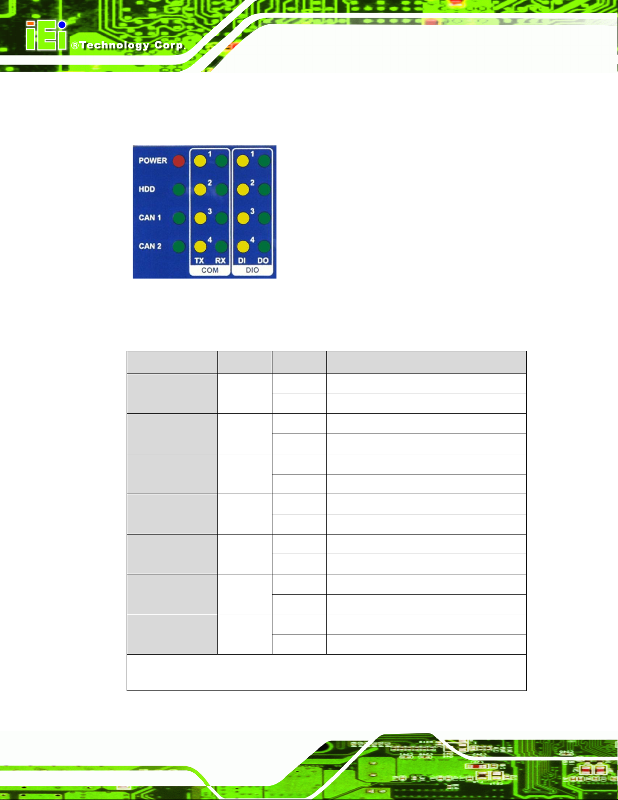
Figure 1-4: DRPC-100-CV-LED LED Indicators
LED
Color
Status
Description
POWER
Red
On
System power is on
Off
System power is off
HDD
Green
Blinking
Storage device accessing
Off
Storage device not accessing
CAN 1~2
Green
On
Active
Off
Inactive
COM TX 1~4
Yellow
On
COM port is transmitting data
Off
COM port is not transmitting data
COM RX 1~4
Green
On
COM port is receiving data
Off
COM port is not receiving data
DIO DI 1~4*
Yellow
On
Active
Off
Inactive
DIO DO 1~4*
Green
On
Active
Off
Inactive
* When the DIO is set to pull-high, the DIO LED indicators always light up.
When the DIO is set to pull-low, the DIO LED indicators are always off.
Table 1-2: DRPC-100-CV-LED LED Definitions
1.5 LED Indicators (DRPC-100-CV-LED Only)
The LED indicators on the front panel of the DRPC-100-CV-LED are shown in Figure 1-4.
All the LED definitions are listed in Table 1-2.
Page 21
DRPC-100 Embedded System
Page 7
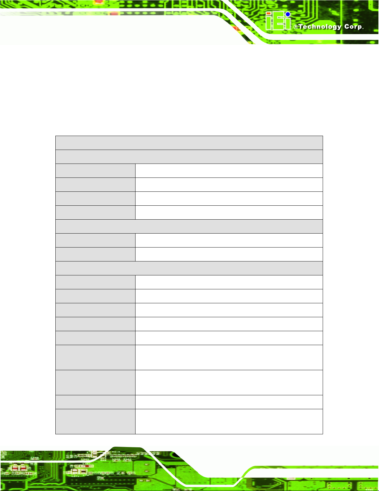
Specifications
System
CPU
1.86 GHz Intel® Atom™ N2800 dual-core processor
Chipset
Intel® NM10
Memory
1 x 2 GB 204-pin 1066 MHz DDR3 SO-DIMM (system max. 4 GB)
Ethernet Controller
Dual GbE by Realtek RTL8111E controllers
Storage
SATA
mSATA and SATA DOM support
CompactFlash®
1 x CompactFlash® card slot
I/O and Indicators
Ethernet
2 x RJ-45 ports
RS-232
2 x DB-9 serial ports with 3KV isolation protection
RS-422/RS-485
2 x DB-9 serial ports with 3KV isolation protection
USB
4 x USB 2.0 ports
Display
1 x VGA port (supports resolution up to 1920 x 1200@ 60Hz)
Digital I/O
1 x Phoenix terminal block with 3KV isolation protection
(8-bit, 4-bit input/4-bit output)
CAN-bus
1 x Phoenix terminal block with 3KV isolation protection (supports
2-port CAN-bus)
Interior Expansion
1 x PCIe Mini card slot (full size)
Indicators
LED (for DRPC-100-CV-LED-R10)
OLED (for DRPC-100-CV-OLED-R10)
1.6 Programmable OLED Display (DRPC-100-CV-OLED Only)
For programming the OLED display on the front panel of the DRPC-100-CV-OLED, refer
to Chapter 6.
1.7 Technical Specifications
The DRPC-100 technical specifications are listed in Table 1-3.
Page 22
DRPC-100 Embedded System
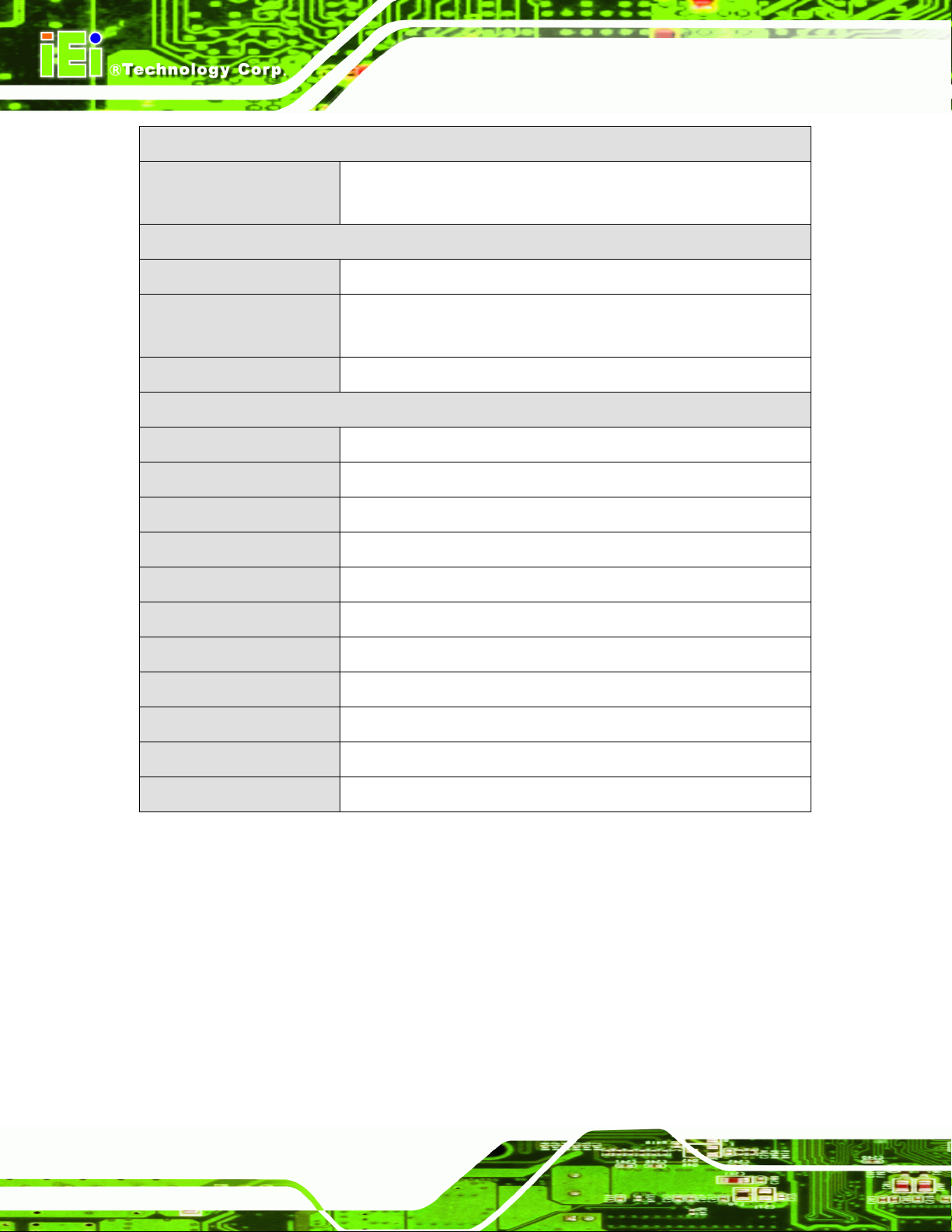
Page 8
Specifications
Buttons
Power button
Reset button
Power
Power Input
9V~28V DC (3-pin terminal block)
Power Consumption
12V@1.85A (1.86 GHz Intel® Atom™ N2800 dual-core CPU with
2 GB 1066 MHz DDR3 SO-DIMM)
AT/ATX Mode
AT/ATX switch
Environmental and Mechanical
Mounting
DIN rail, desktop
Operating Temperature
-25C~65C (with SSD)
Storage Temperature
-25C~70C
Humidity
5%~95%, non-condensing
Chassis Construction
Extruded aluminum alloy for fanless support
Chassis Color
Black
Operating Shock
Half-sine shock test 5G/11ms, 3 shocks per axis
Operating Vibration
MIL-STD-810F 514.5 C-1 (HDD), MIL-STD-810F 514.5 C-2 (SSD)
Safety
CE/FCC
Weight (Net/Gross)
1 Kg/2 Kg
Physical Dimensions
59.4 mm x 170 mm x 140 mm (W x H x D)
Table 1-3: Technical Specifications
Page 23

DRPC-100 Embedded System
Page 9
Figure 1-5: Physical Dimensions (millimeters)
1.8 Dimensions
The physical dimensions are shown below:
Page 24

DRPC-100 Embedded System
Page 10
Chapter
2
2 Unpacking
Page 25
DRPC-100 Embedded System
Page 11
WARNING:
Failure to take ESD precautions during installation may result in
permanent damage to the DRPC-100 and severe injury to the user.
2.1 Anti-static Precautions
Electrostatic discharge (ESD) can cause serious damage to electronic components,
including the DRPC-100. Dry climates are especially susceptible to ESD. It is therefore
critical that whenever the DRPC-100 or any other electrical component is handled, the
following anti-static precautions are strictly adhered to.
Wear an anti-static wristband: Wearing a simple anti-static wristband can
help to prevent ESD from damaging the board.
Self-grounding: Before handling the board touch any grounded conducting
material. During the time the board is handled, frequently touch any
conducting materials that are connected to the ground.
Use an anti-static pad: When configuring the DRPC-100, place it on an
antic-static pad. This reduces the possibility of ESD damaging the DRPC-100.
2.2 Unpacking Precautions
When the DRPC-100 is unpacked, please do the following:
Follow the anti-static precautions outlined in Section 2.1.
Make sure the packing box is facing upwards so the DRPC-100 does not fall
out of the box.
Make sure all the components shown in Section 2.3 are present.
Page 26

DRPC-100 Embedded System
Page 12
NOTE:
If some of the components listed in the checklist below are missing,
please do not proceed with the installation. Contact the IEI reseller or
vendor you purchased the DRPC-100 from or contact an IEI sales
representative directly. To contact an IEI sales representative, please
send an email to sales@iei.com.tw.
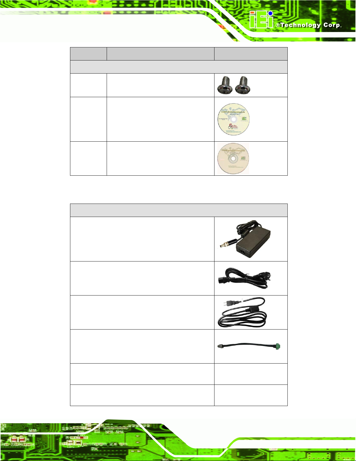
Quantity
Item and Part Number
Image
Standard
1
DRPC-100
or
3
3-pin terminal block
2
5-pin terminal block
1
DIN rail mounting bracket
(50 mm x 45 mm x 8.7 mm)
3
Mounting bracket screw
(P/N: 44015-030051-RS)
2.3 Unpacking Checklist
The DRPC-100 is shipped with the following components:
Page 27
DRPC-100 Embedded System
Page 13
Quantity
Item and Part Number
Image
Standard
2
Screw (for securing an PCIe Mini card)
(P/N: 44003-020031-RS)
1
One Key Recovery CD
1
User manual and driver CD
Optional
Power adapter
(P/N: 63000-FSP036RAB610-RS)
Power cord, European standard, 1830 mm
(P/N: 32000-000002-RS)
Power cord, American standard, 1830 mm
(P/N: 32000-000025-RS)
Power cable, DC jack (5.5x2.5) to 3-pin terminal
block, 200 mm
(P/N: 32102-026500-100-RS)
Flash disk, mSATA, 2GB~32GB, 0C ~ 70C
(P/N: IPE-5200IM-xxx)
Flash disk, mSATA, 2GB~32GB, -40C ~ 85C
(P/N: IPE-5200VM-xxx)
The following table lists the optional items that can be purchased separately.
Page 28

DRPC-100 Embedded System
Page 14
Chapter
3
3 Installation
Page 29

DRPC-100 Embedded System
Page 15
WARNING:
Some surfaces of the equipment may become hot during operation.
The surface temperature may be up to several tens of degrees hotter
than the ambient temperature. Under these circumstances, the
equipment needs to be protected against accidental contact.
3.1 Installation Precautions
During installation, be aware of the precautions below:
Read the user manual: The user manual provides a complete description of
the DRPC-100, installation instructions and configuration options.
DANGER! Disconnect Power: Power to the DRPC-100 must be
disconnected during the installation process. Failing to disconnect the power
may cause severe injury to the body and/or damage to the system.
Qualified Personnel: The DRPC-100 must be installed and operated only by
trained and qualified personnel. Maintenance, upgrades, or repairs may only
be carried out by qualified personnel who are familiar with the associated
dangers.
Air Circulation: Make sure there is sufficient air circulation when installing the
DRPC-100. The DRPC-100’s cooling vents must not be obstructed by any
objects. Blocking the vents can cause overheating of the DRPC-100. Leave at
least 5 cm of clearance around the DRPC-100 to prevent overheating.
Grounding: The DRPC-100 should be properly grounded. The voltage feeds
must not be overloaded. Adjust the cabling and provide external overcharge
protection per the electrical values indicated on the label attached to the back
of the DRPC-100.
3.1.1 High Surface Temperature
The equipment is intended for installation in a RESTRICTED ACCESS LOCATION.
Page 30

DRPC-100 Embedded System
Page 16
Figure 3-1: CF Card Slot Cover
Access can only be gained by SERVICE PERSONS or by USERS who have
been instructed about the reasons for the restrictions applied to the location
and about any precautions that shall be taken.
Access is through the use of a TOOL or lock and key, or other means of
security, and is controlled by the authority responsible for the location.
3.2 CF Card Installation
To install the CF card, please follow the steps below:
Step 1: Locate the CF card slot on the top panel of the DRPC-100.
Step 2: Release the retention screw that secures the CF card slot cover, and then open
the cover as shown in Figure 3-1.
Step 3: Insert the CF card into the slot (Figure 3-2).
Page 31

DRPC-100 Embedded System
Page 17
Figure 3-2: CF Card Installation
Figure 3-3: Replacing the CF Card Slot Cover
Step 4: Replace the CF card slot cover and secure it with the retention screw (Figure
3-3).
3.3 Motherboard Removal
Before the jumper settings can be configured and the mSATA SSD can be installed, the
motherboard must be removed from the DRPC-100. Follow the steps below to complete
the task.
Step 1: Remove the retention screws indicated in Figure 3-4.
Page 32
DRPC-100 Embedded System
Page 18
Figure 3-4: Retention Screws
Figure 3-5: Hex Nuts on the Front Panel
Step 2: Remove the hex nuts on the front panel (Figure 3-5). Gently pull the front panel
out of the DRPC-100.
Step 3: Remove the hex nuts on the top panel (Figure 3-6). Gently pull the top panel out
of the DRPC-100.
Page 33

DRPC-100 Embedded System
Page 19
Figure 3-6: Hex Nuts on the Top Panel
Figure 3-7: Retention Screws on the Motherboard
Step 4: Lift the motherboard secured with the side cover off the DRPC-100.
Step 5: Release the motherboard from the side cover by removing the four retention
screws (Figure 3-7) on the solder side of the motherboard.
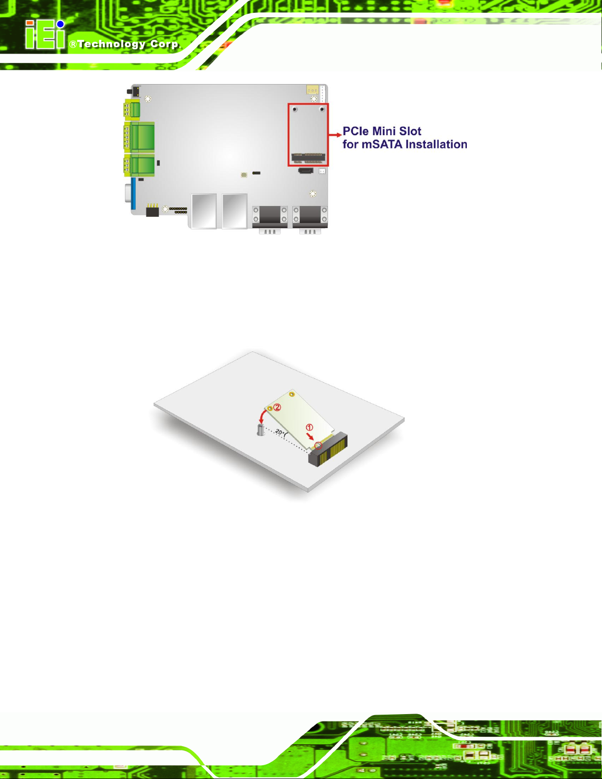
3.4 mSATA SSD Installation
The DRPC-100 has one PCIe Mini slot on the motherboard for mSATA SSD installation.
To install the mSATA SSD, follow the instructions below.
Step 1: Before accessing the motherboard, it has to be removed from the DRPC-100.
Following the instruction described in Section 3.3 to complete the task.
Step 2: Locate the PCIe Mini slot on the motherboard (Figure 3-8).
Page 34
DRPC-100 Embedded System
Page 20
Figure 3-8: PCIe Mini Slot Location
Figure 3-9: Inserting the PCIe Mini Card into the Socket
Step 3: Insert into the socket at an angle. Line up the notch on the card with the notch
on the connector. Slide the PCIe Mini card into the socket at an angle of about
20º (Figure 3-9).
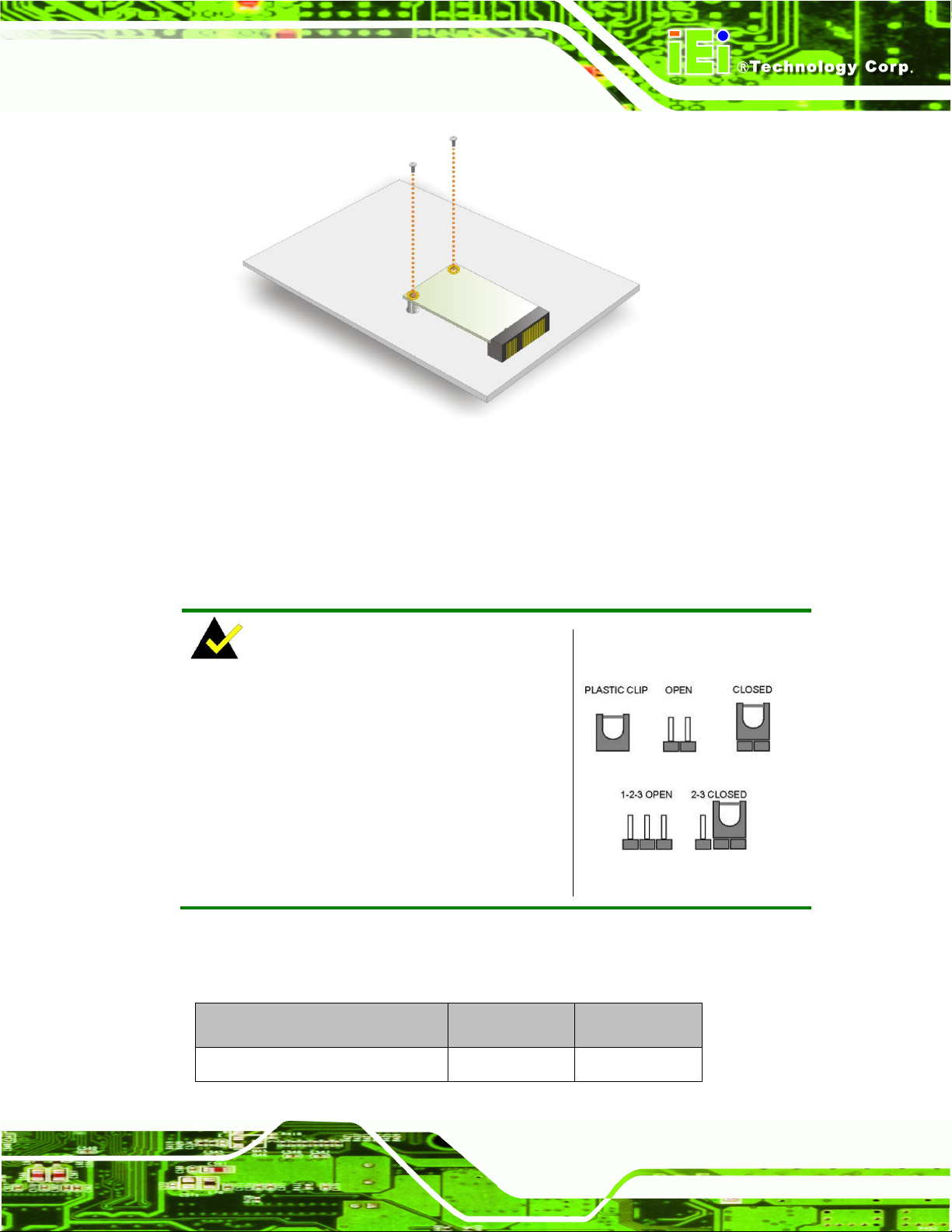
Step 4: Secure the PCIe Mini card. Secure the PCIe Mini card with the supplied
retention screws (Figure 3-10).
Page 35
DRPC-100 Embedded System
Page 21
Figure 3-10: Securing the PCIe Mini Card
NOTE:
A jumper is a metal bridge used to close an
electrical circuit. It consists of two or three metal
pins and a small metal clip (often protected by a
plastic cover) that slides over the pins to connect
them. To CLOSE/SHORT a jumper means
connecting the pins of the jumper with the plastic
clip and to OPEN a jumper means removing the
plastic clip from a jumper.
Description
Label
Type
Clear CMOS
JP1
3-pin header
Step 5: Reassemble the whole system. Step 0:
3.5 Jumper Settings
The jumpers on the DRPC-100 motherboard are listed in 543HTable 3-1. The JP3 and JP4
jumpers are preconfigured for the DRPC-100. Users should not change these jumpers.
Page 36

DRPC-100 Embedded System
Page 22
CAN-bus 1 long wire transmitting
JP3
2-pin header
CAN-bus 2 long wire transmitting
JP4
2-pin header
Table 3-1: Jumpers
Jumper Label:
JP1
Jumper Type:
3-pin header
Jumper Settings:
See Table 3-2
Jumper Location:
See 550HFigure 3-11
Clear CMOS
Description
Short 1 - 2
Keep CMOS Setup
Default
Short 2 - 3
Clear CMOS Setup
Table 3-2: Clear CMOS Jumper Settings
3.5.1 Access the Jumpers
To access the jumpers, the motherboard has to be removed from the DRPC-100. Follow
the instruction described in Section 3.3 to complete the task.
3.5.2 Clear CMOS Jumper
If the DRPC-100 fails to boot due to improper BIOS settings, the clear CMOS jumper
clears the CMOS data and resets the system BIOS information. To do this, use the jumper
cap to close the pins for a few seconds then remove the jumper clip.
If the “CMOS Settings Wrong” message is displayed during the boot up process, the fault
may be corrected by pressing the F1 to enter the CMOS Setup menu. Do one of the
following:
Enter the correct CMOS setting
Load Optimal Defaults
Load Failsafe Defaults.
After having done one of the above, save the changes and exit the CMOS Setup menu.
The clear CMOS jumper settings are shown in Table 3-2.
Page 37

DRPC-100 Embedded System
Page 23
Figure 3-11: Clear CMOS Jumper Location
Figure 3-12: AT/ATX Switch Location
The clear CMOS jumper location is shown in 552HFigure 3-11 below.
3.6 AT/ATX Mode Selection
AT and ATX power modes can both be used on the DRPC-100. The selection is made
through an AT/ATX switch on the top panel as shown below (Figure 3-12).
Page 38

DRPC-100 Embedded System
Page 24
Figure 3-13: DIN Rail Mounting Bracket
Figure 3-14: Attach the DIN Rail to the Mounting Bracket
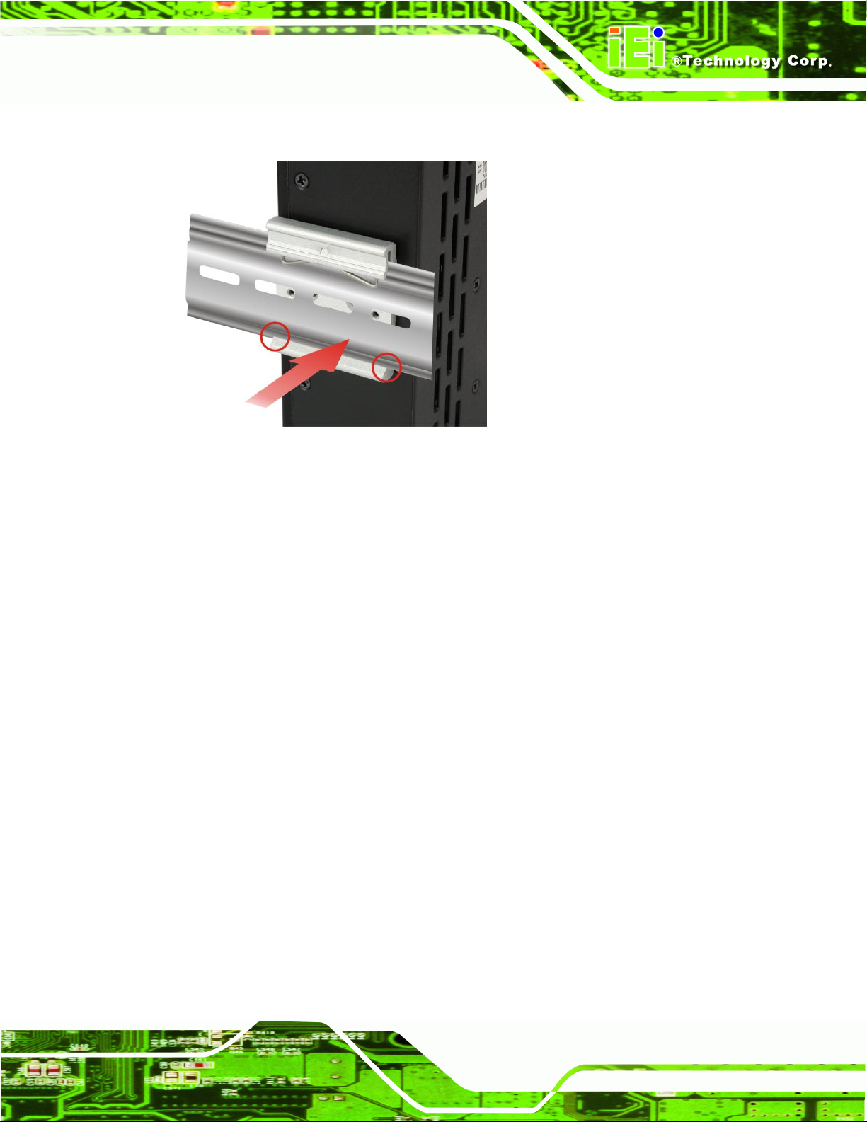
3.7 Mounting the System
The DRPC-100 embedded system can be mounted onto a DIN rail. Follow the steps
below to complete the task.
Step 1: Attach the supplied DIN rail mounting bracket to the rear panel of the embedded system.
Secure the bracket to the embedded system with there retention screws (762H762HFigure 3-13).
Step 2: Attach the upper edge of the DIN rail to the mounting bracket as shown in
Figure 3-14.
Page 39
DRPC-100 Embedded System
Page 25
Figure 3-15: Mounting the DIN Rail
CN Label:
CAN
CN Type:
2 x 3-pin terminal block
CN Location:
See Figure 1-3
CN Pinouts:
See Table 3-3 and Figure 3-16
Step 3: Push the DIN rail inward until it clips in place (Figure 3-15).
3.8 External Peripheral Interface Connectors
The DRPC-100 has the following connectors. Detailed descriptions of the connectors can
be found in the subsections below.
8-bit DIO
CAN-bus
Ethernet
Power input
RS-232
RS-422/485
USB
3.8.1 CAN-bus Terminal Block
VGA
Page 40

DRPC-100 Embedded System
Page 26
Pin
Description
Pin
Description
1
CAN1H
2
CAN2H
3
CAN1L
4
CAN2L
5
CAN1_GROUND
6
CAN2_GROUND
Table 3-3: CAN-bus Terminal Block Pinouts
Figure 3-16: CAN-bus Terminal Block Pinout Location
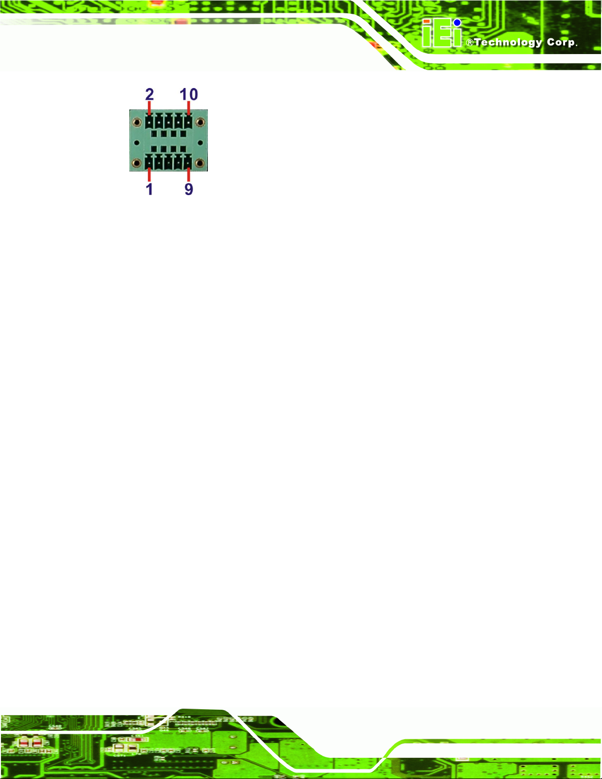
CN Label:
DIO
CN Type:
2 x 5-pin terminal block
CN Location:
See Figure 1-3
CN Pinouts:
See Table 3-4 and Figure 3-17
Pin
Description
Pin
Description
1
DGI_0
2
DGO_0
3
DGI_1
4
DGO_1
5
DGI_2
6
DGO_2
7
DGI_3
8
DGO_3
9
Isolator GND
10
Isolator Vin
Table 3-4: DIO Terminal Block Pinouts
The Phoenix terminal block with 3KV isolation protection supports 2-port CAN-bus. The
pinouts of the terminal block are shown in the table below.
3.8.2 Digital Input/Output Terminal Block
The digital I/O terminal block provides programmable input and output for external
devices. The pinouts for the digital I/O terminal block are listed in the table below.
Page 41
DRPC-100 Embedded System
Page 27
Figure 3-17: DIO Terminal Block Pinout Location
CN Type:
RJ-45
CN Location:
See Figure 1-2
CN Pinouts:
See Table 3-5
3.8.3 LAN Connectors
The LAN connectors allow connection to an external network.
Step 1: Locate the RJ-45 connectors. The locations of the RJ-45 connectors are
shown in Figure 1-2.
Step 2: Align the connectors. Align the RJ-45 connector on the LAN cable with one of
the RJ-45 connectors on the DRPC-100. See Figure 3-18.
Page 42

DRPC-100 Embedded System
Page 28
Figure 3-18: LAN Connection
Pin
Description
Pin
Description
1
MD0+
5
MD2+
2
MD0-
6
MD2-
3.
MD1+
7
MD3+
4.
MD1-
8
MD3-
Table 3-5: LAN Pinouts
Figure 3-19: RJ-45 Ethernet Connector
Step 3: Insert the LAN cable RJ-45 connector. Once aligned, gently insert the LAN
cable RJ-45 connector into the on-board RJ-45 connector.
The RJ-45 Ethernet connector has two status LEDs, one green and one yellow. The green
LED indicates activity on the port and the yellow LED indicates the port is linked. See
Table 3-6.
Page 43

DRPC-100 Embedded System
Page 29
Activity/Link LED
Speed LED
STATUS
DESCRIPTION
STATUS
DESCRIPTION
Off
No link
Off
10 Mbps connection
Yellow
Linked
Green
100 Mbps connection
Blinking
TX/RX activity
Orange
1 Gbps connection
Table 3-6: RJ-45 Ethernet Connector LEDs
CN Type:
3-pin terminal block
CN Location:
See Figure 1-3
CN Pinouts:
See Table 3-7 and Figure 3-20
Pin
Description
Pin
Description
1
9~28V input
3
GND
2
9~28V input
Table 3-7: 3-pin Power Terminal Block Pinouts
Figure 3-20: 3-pin Power Terminal Block Pinout Location
3.8.4 Power Input, 3-pin Terminal Block
Connect the leads of a 9V~28V DC power supply into the terminal block. Make sure that
the power and ground wires are attached to the correct sockets of the connector.
Page 44

DRPC-100 Embedded System
Page 30
CN Label:
COM1 and COM2
CN Type:
DB-9 connectors
CN Location:
See Figure 1-2
CN Pinouts:
See Table 3-8 and Figure 3-22
Figure 3-21: RS-232 Serial Device Connector
3.8.5 RS-232 Serial Port Connectors
RS-232 serial port devices can be attached to the DB-9 ports on the front panel.
Step 1: Locate the DB-9 connector. The locations of the DB-9 connectors are shown in
Figure 1-2.
Step 2: Insert the serial connector. Insert the DB-9 connector of a serial device into
the DB-9 connector on the external peripheral interface. See Figure 3-21.
Step 3: Secure the connector. Secure the serial device connector to the external
interface by tightening the two retention screws on either side of the connector.
Page 45

DRPC-100 Embedded System
Page 31
Pin
Description
Pin
Description
1
DCD
6
DSR
2
RXD
7
RTS 3 TXD 8 CTS 4 DTR 9 RI 5 GND
Table 3-8: RS-232 Serial Port Pinouts
Figure 3-22:RS-232 Serial Port Pinout Location
CN Label:
COM3 and COM4
CN Type:
DB-9 connectors
CN Location:
See Figure 1-2
CN Pinouts:
See Table 3-9 and Figure 3-24
3.8.6 RS-422/485 Serial Port Connectors
RS-422/485 serial port devices can be attached to the DB-9 ports on the front panel.
Step 1: Locate the DB-9 connector. The locations of the DB-9 connectors are shown in
Figure 1-2.
Step 2: Insert the serial connector. Insert the DB-9 connector of a serial device into
the DB-9 connector on the external peripheral interface. See Figure 3-23.
Page 46

DRPC-100 Embedded System
Page 32
Figure 3-23: RS-422/485 Serial Device Connector
Pin
Description
Pin
Description
1
RS422TX-/RS485D-
6
NC
2
RS422TX+/RS485D+
7
NC
3
RS422RX+
8
NC
4
RS422RX
9
NC
5
GND
Table 3-9: RS-422/485 Serial Port Pinouts
Figure 3-24: RS-422/485Serial Port Pinout Location
Step 3: Secure the connector. Secure the serial device connector to the external
interface by tightening the two retention screws on either side of the connector.
Page 47

DRPC-100 Embedded System
Page 33
CN Type:
USB port
CN Location:
See Figure 1-2
CN Pinouts:
See Table 3-10
Figure 3-25: USB Device Connection
3.8.7 USB Connectors
The USB ports are for connecting USB peripheral devices to the system.
Step 1: Locate the USB connectors. The locations of the USB connectors are shown
in Figure 1-2.
Step 2: Align the connectors. Align the USB device connector with one of the
connectors. See Figure 3-25.
Step 3: Insert the device connector. Once aligned, gently insert the USB device
connector into the on-board connector.
Page 48

DRPC-100 Embedded System
Page 34
Pin
Description
Pin
Description
1
VCC 5 VCC 2 DATA-
6
DATA-
3
DATA+
7
DATA+
4
GROUND
8
GROUND
Table 3-10: USB Port Pinouts
CN Label:
VGA
CN Type:
15-pin Female
CN Location:
See Figure 1-3
CN Pinouts:
See Figure 3-27 and Table 3-11
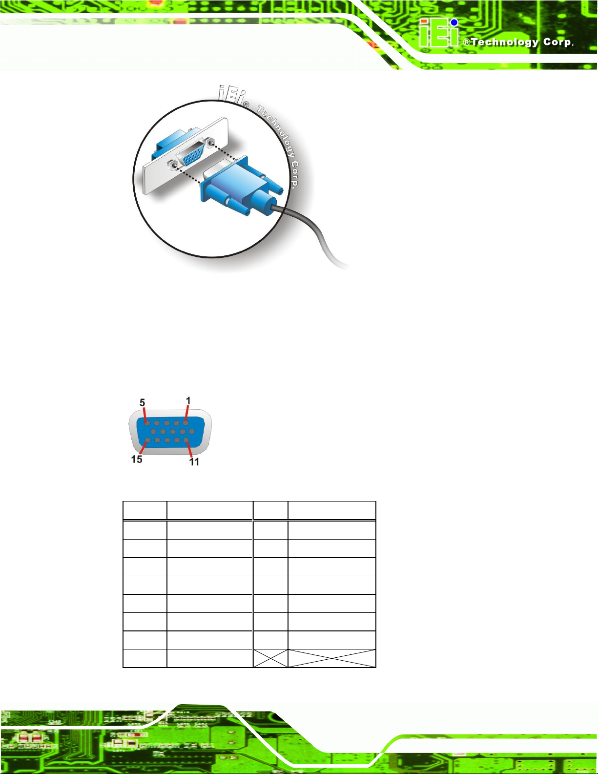
3.8.8 VGA Connector
The VGA connector connects to a monitor that accepts VGA video input.
Step 1: Locate the female DB-15 connector. The location of the female DB-15
connector is shown in Figure 1-3.
Step 2: Align the VGA connector. Align the male DB-15 connector on the VGA screen
cable with the female DB-15 connector on the external peripheral interface.
Step 3: Insert the VGA connector. Once the connectors are properly aligned with,
insert the male connector from the VGA screen cable into the female connector
on the DRPC-100. See Figure 3-26.
Page 49
DRPC-100 Embedded System
Page 35
Figure 3-26: VGA Connector
Figure 3-27: VGA Connector
Pin
Description
Pin
Description
1
RED 2 GREEN
3
BLUE
4
NC 5 GND
6
GND
7
GND
8
GND
9
VCC
10
GND
11
NC
12
DDC DAT
13
HSYNC
14
VSYNC
15
DDCCLK
Table 3-11: VGA Connector Pinouts
Step 4: Secure the connector. Secure the DB-15 VGA connector from the VGA
monitor to the external interface by tightening the two retention screws on either
side of the connector.
Page 50

DRPC-100 Embedded System
Page 36
NOTE:
The content of the CD may vary throughout the life cycle of the product
and is subject to change without prior notice. Visit the IEI website or
contact technical support for the latest updates.
3.9 Driver Installation
The following drivers can be installed on the system:
Chipset
VGA
LAN
To install the drivers, insert the CD into an optical disk drive connected to the system, and
then locate the corresponding driver folders to install all the drivers listed above.
Page 51

DRPC-100 Embedded System
Page 37
Chapter
4
4 System Maintenance
Page 52

DRPC-100 Embedded System
Page 38
WARNING!
Before accessing any DRPC-100 internal components, make sure all
power to the system has been disconnected. Failing to do so may
cause severe damage to the DRPC-100 and injury to the user.
WARNING!
Please take antistatic precautions when working with the internal
components. The interior of the DRPC-100 contains very sensitive
electronic components. These components are easily damaged by
electrostatic discharge (ESD). Before working with the internal
components, make sure all anti-static precautions described earlier
have been observed.
4.1 System Maintenance Introduction
The following system components may require maintenance.
Motherboard
SO-DIMM module
If these components fail, they must be replaced. Please contact the system reseller or
vendor to purchase replacement parts. Replacement instructions for the above listed
components are described below.
4.2 Motherboard Replacement
A user cannot replace a motherboard. If the motherboard fails it must be shipped back to
IEI to be replaced. If the system motherboard has failed, please contact the system
vendor, reseller or an IEI sales person directly.
Page 53

DRPC-100 Embedded System
Page 39
Figure 4-1: SO-DIMM Module Location
4.3 SO-DIMM Replacement
To install/replace the SO-DIMM modules, please follow the steps below.
Step 1: Remove the motherboard from the DRPC-100. Refer to Section 3.3.
Step 2: Locate the SO-DIMM module on the motherboard.
Step 3: Release the SO-DIMM module by pulling both the spring retainer clips outward
from the socket.
Step 4: Grasp the SO-DIMM module by the edges and carefully pull it out of the socket.
Step 5: Install the new SO-DIMM module by pushing it into the socket at an angle
(Figure 4-2).
Step 6: Gently push the rear of the SO-DIMM module down (Figure 4-2). The spring
retainer clips clip into place and secure the SO-DIMM module in the socket.
Page 54

DRPC-100 Embedded System
Page 40
Figure 4-2: SO-DIMM Module Installation
Step 7: Push the new SO-DIMM module until it engages and the white plastic end clips
click into place. Make sure the end clips are fully secured after installation.Step 0:
Page 55
DRPC-100 Embedded System
Page 41
Chapter
5
5 BIOS
Page 56
DRPC-100 Embedded System
Page 42
Key
Function
Up arrow
Move to previous item
Down arrow
Move to next item
Left arrow
Move to the item on the left hand side
Right arrow
Move to the item on the right hand side
+
Increase the numeric value or make changes
-
Decrease the numeric value or make changes
Page Up key
Move to the next page
Page Dn key
Move to the previous page
5.1 Introduction
The BIOS is programmed onto the BIOS chip. The BIOS setup program allows changes to
certain system settings. This chapter outlines the options that can be changed.
5.1.1 Starting Setup
The UEFI BIOS is activated when the computer is turned on. The setup program can be
activated in one of two ways.
1. Press the DEL or F2 key as soon as the system is turned on or
2. Press the DEL or F2 key when the “Press DEL or F2 to enter SETUP”
message appears on the screen.
If the message disappears before the DEL or F2 key is pressed, restart the computer and
try again.
5.1.2 Using Setup
Use the arrow keys to highlight items, press ENTER to select, use the PageUp and
PageDown keys to change entries, press F1 for help and press ESC to quit. Navigation
keys are shown in the following table.
Page 57

DRPC-100 Embedded System
Page 43
Key
Function
Esc key
Main Menu – Quit and not save changes into CMOS
Status Page Setup Menu and Option Page Setup Menu --
Exit current page and return to Main Menu
F1
General help, only for Status Page Setup Menu and Option
Page Setup Menu
F2
Load previous values
F3
Load optimized defaults
F4
Save changes and Exit BIOS
Table 5-1: BIOS Navigation Keys
5.1.3 Getting Help
When F1 is pressed a small help window describing the appropriate keys to use and the
possible selections for the highlighted item appears. To exit the Help Window press ESC or
the F1 key again.
5.1.4 Unable to Reboot After Configuration Changes
If the computer cannot boot after changes to the system configuration are made, CMOS
defaults. Use the jumper described in Chapter 3.
5.1.5 BIOS Menu Bar
The menu bar on top of the BIOS screen has the following main items:
Main – Changes the basic system configuration.
Advanced – Changes the advanced system settings.
Chipset – Changes the chipset settings.
Boot – Changes the system boot configuration.
Security – Sets User and Supervisor Passwords.
Save & Exit – Selects exit options and loads default settings.
The following sections completely describe the configuration options found in the menu
items at the top of the BIOS screen and listed above.
Page 58

DRPC-100 Embedded System
Page 44
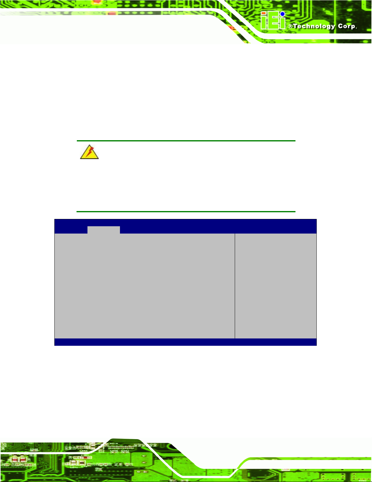
Aptio Setup Utility – Copyright (C) 2011 American Megatrends, Inc.
Main
Advanced
Chipset
Boot
Security
Save & Exit
BIOS Information
BIOS Vendor American Megatrends
Core Version 4.6.5.1 0.13
Compliancy UEFI 2.3; PI 1.2
Project Version E407AR06.ROM
Build Date and Time 06/21/2012 11:53:40
System Date [Wed 10/24/2012]
System Time [15:10:27]
Access Level Administrator
Set the Date. Use Tab to
switch between Data
elements.
----------------------
: Select Screen
: Select Item
Enter: Select
+/-: Change Opt.
F1: General Help
F2: Previous Values
F3: Optimized Defaults
F4: Save & Exit
ESC: Exit
Version 2.14.1219. Copyright (C) 2011 American Megatrends, Inc.
BIOS Menu 1: Main
5.2 Main
The Main BIOS menu (BIOS Menu 1) appears when the BIOS Setup program is entered.
The Main menu gives an overview of the basic system information.
System Overview
The BIOS Information lists a brief summary of the BIOS. The fields in BIOS Information
cannot be changed. The items shown in the system overview include:
BIOS Vendor: Installed BIOS vendor
Core Version: Current BIOS version
Project Version: the board version
Build Date and Time: Date and time the current BIOS version was made
The System Overview field also has two user configurable fields:
System Date [xx/xx/xx]
Use the System Date option to set the system date. Manually enter the day, month and
year.
Page 59
DRPC-100 Embedded System
Page 45
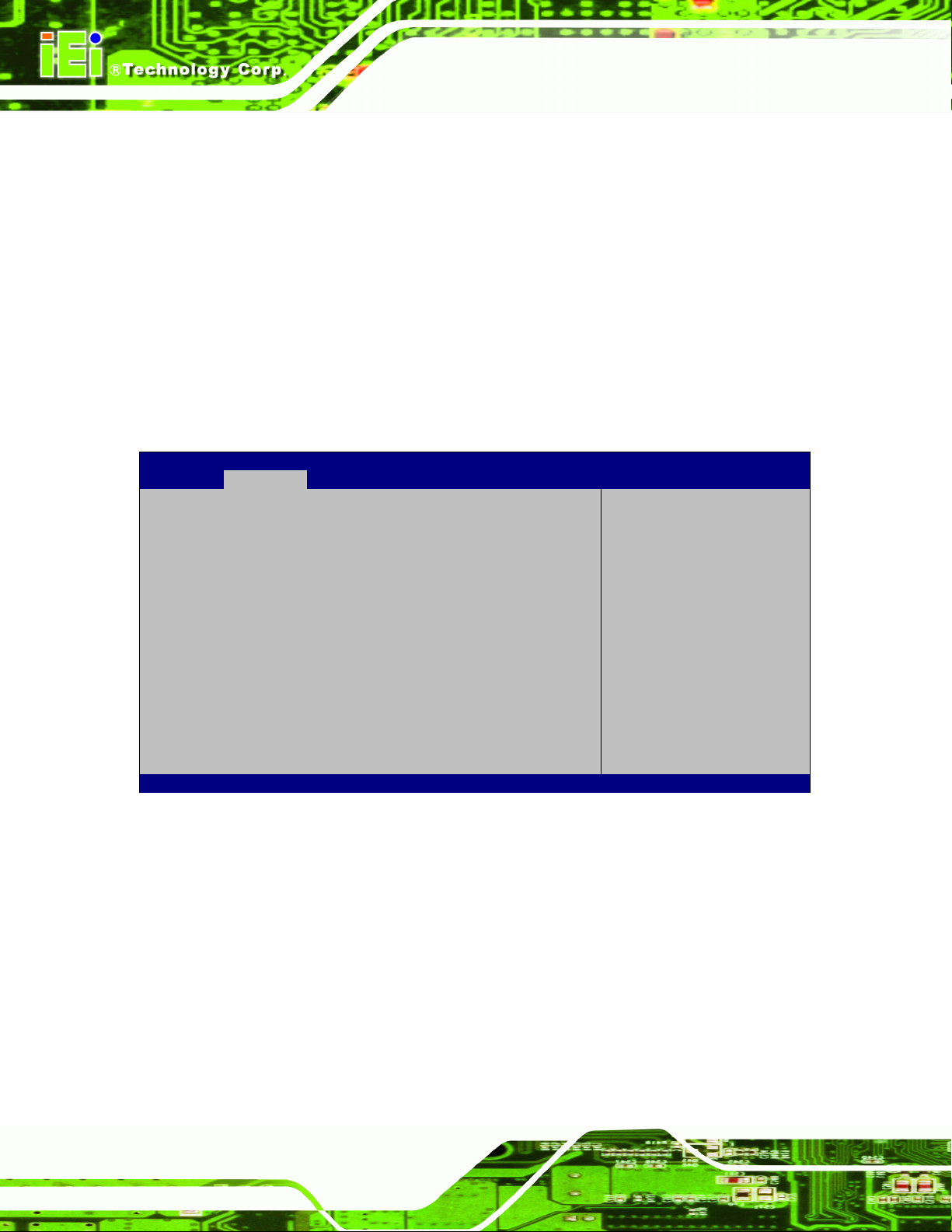
WARNING!
Setting the wrong values in the sections below may cause the system
to malfunction. Make sure that the settings made are compatible with
the hardware.
Aptio Setup Utility – Copyright (C) 2011 American Megatrends, Inc.
Main
Advanced
Chipset
Boot
Security
Save & Exit
> ACPI Settings
> CPU Configuration
> IDE Configuration
> USB Configuration
> F81866 Super IO Configuration
> F81866 H/M Monitor
> Serial Port Console Redirection
System ACPI Parameters.
----------------------
: Select Screen
: Select Item
Enter: Select
+/-: Change Opt.
F1: General Help
F2: Previous Values
F3: Optimized Defaults
F4: Save & Exit
ESC: Exit
Version 2.14.1219. Copyright (C) 2011 American Megatrends, Inc.
BIOS Menu 2: Advanced
System Time [xx:xx:xx]
Use the System Time option to set the system time. Manually enter the hours, minutes
and seconds.
5.3 Advanced
Use the Advanced menu (BIOS Menu 2) to configure the CPU and peripheral devices
through the following sub-menus:
Page 60

DRPC-100 Embedded System
Page 46
Aptio Setup Utility – Copyright (C) 2011 American Megatrends, Inc.
Advanced
ACPI Settings
ACPI Sleep State [S3 (Suspend to RAM)]
Select the highest ACPI
sleep state the system
will enter when the
SUSPEND button is
pressed.
----------------------
: Select Screen
: Select Item
Enter: Select
+/-: Change Opt.
F1: General Help
F2: Previous Values
F3: Optimized Defaults
F4: Save & Exit
ESC: Exit
Version 2.14.1219. Copyright (C) 2011 American Megatrends, Inc.
BIOS Menu 3: ACPI Configuration
Suspend Disabled
S1 (CPU Stop
Clock)
The system enters S1(POS) sleep state. The
system appears off. The CPU is stopped; RAM is
refreshed; the system is running in a low power
mode.
S3 (Suspend to
RAM)
DEFAULT
The caches are flushed and the CPU is powered
off. Power to the RAM is maintained. The
computer returns slower to a working state, but
more power is saved.
5.3.1 ACPI Settings
The ACPI Settings menu (BIOS Menu 3) configures the Advanced Configuration and
Power Interface (ACPI) options.
ACPI Sleep State [S3 (Suspend to RAM)]
Use the ACPI Sleep State option to specify the sleep state the system enters when it is
not being used.
Page 61

DRPC-100 Embedded System
Page 47
Aptio Setup Utility – Copyright (C) 2011 American Megatrends, Inc.
Advanced
CPU Configuration
Processor Type Intel(R) Atom(TM)
CPU N2800 @ 1.86GHz
EMT64 Supported
Processor Speed 1865 MHz
System Bus Speed 533 MHz
Ratio Status 14
Actual Ratio 14
System Bus Speed 533 MHz
Processor Stepping 30661
Microcode Revision 262
L1 Cache RAM 2x56 k
L2 Cache RAM 2x512 k
Processor Core Dual
Hyper-Threading Supported
Hyper-Threading [Enabled]
Enabled for Windows XP
and Linux (OS optimized
for Hyper-Threading
Technology) and Disabled
for other OS (OS not
optimized for
Hyper-Threading
Technology).
----------------------
: Select Screen
: Select Item
Enter: Select
+/-: Change Opt.
F1: General Help
F2: Previous Values
F3: Optimized Defaults
F4: Save & Exit
ESC: Exit
Version 2.14.1219. Copyright (C) 2011 American Megatrends, Inc.
BIOS Menu 4: CPU Configuration
5.3.2 CPU Configuration
Use the CPU Configuration menu (BIOS Menu 4) to view detailed CPU specifications
and configure the CPU.
The CPU Configuration menu (BIOS Menu 4) lists the following CPU details:
Processor Type: Lists the brand name of the CPU being used.
EMT64: Indicates if EMT64 is supported by the CPU.
Processor Speed: Lists the CPU processing speed.
System Bus Speed: Lists the system bus speed.
Ratio Status: Lists the ratio status.
Actual Ratio: Lists the ratio of the frequency to the clock speed.
Processor Stepping: Lists the CPU ID.
Microcode Revision: Lists the microcode revision.
L1 Cache RAM: Lists the CPU L1 cache size.
L2 Cache RAM: Lists the CPU L2 cache size.
Processor Core: Lists the number of the processor core.
Hyper-Threading: Indicates if Intel HT Technology is supported by the CPU.
Page 62
DRPC-100 Embedded System
Page 48
Disabled
Disables the Intel Hyper-Threading Technology.
Enabled
DEFAULT
Enables the Intel Hyper-Threading Technology.
Aptio Setup Utility – Copyright (C) 2011 American Megatrends, Inc.
Advanced
SATA Port0 Not Present
SATA Port1 IEI Technology (4.2GB
Configure SATA as [AHCI]
SATA Port 0 Hot Plug [Enabled]
SATA Port 1 Hot Plug [Enabled]
Select a configuration
for SATA Controller.
---------------------
: Select Screen
: Select Item
Enter: Select
+/-: Change Opt.
F1: General Help
F2: Previous Values
F3: Optimized Defaults
F4: Save & Exit
ESC: Exit
Version 2.14.1219. Copyright (C) 2011 American Megatrends, Inc.
BIOS Menu 5: IDE Configuration
IDE
Configures SATA devices as normal IDE device.
AHCI
DEFAULT
Configures SATA devices as AHCI device.
Hyper-Threading [Enabled]
Use the Hyper-Threading function to enable or disable the Intel Hyper-Threading
Technology.
5.3.3 IDE Configuration
Use the IDE Configuration menu (BIOS Menu 5) to change and/or set the configuration
of the SATA devices installed in the system.
Configure SATA as [AHCI]
Use the Configure SATA as option to configure SATA devices as normal IDE or AHCI
devices.
Page 63

DRPC-100 Embedded System
Page 49
Enabled
DEFAULT
Enables the hot-plug function of the SATA port.
Disabled
Disables the hot-plug function of the SATA port..
Aptio Setup Utility – Copyright (C) 2011 American Megatrends, Inc.
Advanced
USB Configuration
USB Devices:
1 Keyboard, 1 Mouse
Legacy USB Support [Enabled]
USB Support Parameters
---------------------
: Select Screen
: Select Item
Enter: Select
+/-: Change Opt.
F1: General Help
F2: Previous Values
F3: Optimized Defaults
F4: Save & Exit
ESC: Exit
Version 2.14.1219. Copyright (C) 2011 American Megatrends, Inc.
BIOS Menu 6: USB Configuration
SATA Port 0/1 Hot Plug [Enabled]
Use the SATA Port 0/1 Hot Plug option to enable or disable the hot-plug function of the
SATA port 0 or 1.
5.3.4 USB Configuration
Use the USB Configuration menu (BIOS Menu 6) to read USB configuration information
and configure the USB settings.
USB Devices
The USB Devices field lists the USB devices that are enabled on the system
Legacy USB Support [Enabled]
Use the Legacy USB Support BIOS option to enable USB mouse and USB keyboard
support. Normally if this option is not enabled, any attached USB mouse or USB keyboard
does not become available until a USB compatible operating system is fully booted with all
USB drivers loaded. When this option is enabled, any attached USB mouse or USB
Page 64
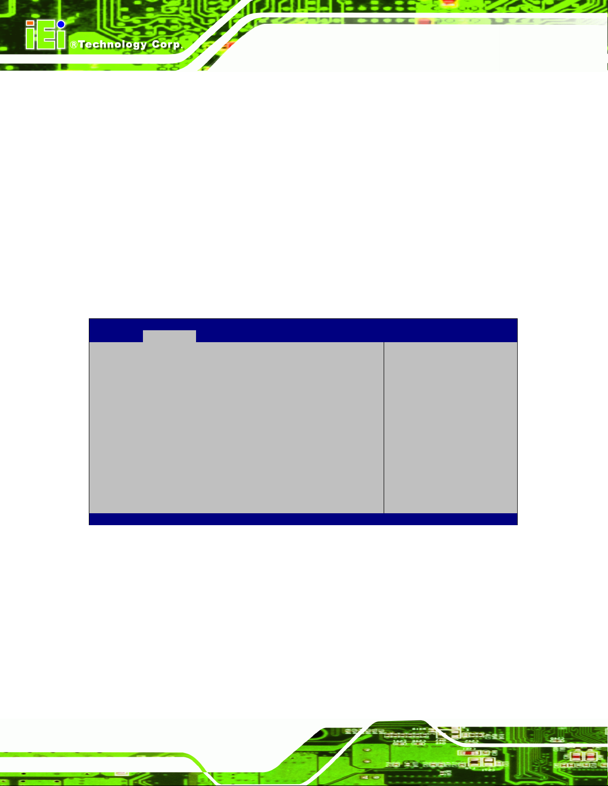
DRPC-100 Embedded System
Page 50
Enabled
DEFAULT
Legacy USB support enabled
Disabled
Legacy USB support disabled
Auto
Legacy USB support disabled if no USB devices are
connected
Aptio Setup Utility – Copyright (C) 2011 American Megatrends, Inc.
Advanced
F81866 Super IO Configuration
F81866 Super IO Chip F81866
> Serial Port 1 Configuration
> Serial Port 2 Configuration
> Serial Port 3 Configuration
> Serial Port 4 Configuration
> Serial Port 5 Configuration
Set Parameters of Serial
Port 1 (COMA)
---------------------
: Select Screen
: Select Item
Enter: Select
+/-: Change Opt.
F1: General Help
F2: Previous Values
F3: Optimized Defaults
F4: Save & Exit
ESC: Exit
Version 2.14.1219. Copyright (C) 2011 American Megatrends, Inc.
BIOS Menu 7: Super IO Configuration
keyboard can control the system even when there is no USB driver loaded onto the
system.
5.3.5 F81866 Super IO Configuration
Use the F81866 Super IO Configuration menu (BIOS Menu 7) to set or change the
configurations for the serial ports.
Page 65

DRPC-100 Embedded System
Page 51
Aptio Setup Utility – Copyright (C) 2011 American Megatrends, Inc.
Advanced
Serial Port n Configuration
Serial Port [Enabled]
Device Settings IO=3F8h; IRQ=4
Change Settings [Auto]
Enable or Disable Serial
Port (COM)
---------------------
: Select Screen
: Select Item
Enter: Select
+/-: Change Opt.
F1: General Help
F2: Previous Values
F3: Optimized Defaults
F4: Save & Exit
ESC: Exit
Version 2.14.1219. Copyright (C) 2011 American Megatrends, Inc.
BIOS Menu 8: Serial Port n Configuration Menu
Disabled
Disable the serial port
Enabled
DEFAULT
Enable the serial port
Auto
DEFAULT
The serial port IO port address and interrupt address
are automatically detected.
IO=3F8h;
IRQ=4
Serial Port I/O port address is 3F8h and the interrupt
address is IRQ4
5.3.5.1 Serial Port n Configuration
Use the Serial Port n Configuration menu (BIOS Menu 8) to configure the serial port n.
5.3.5.1.1 Serial Port 1 Configuration
Serial Port [Enabled]
Use the Serial Port option to enable or disable the serial port.
Change Settings [Auto]
Use the Change Settings option to change the serial port IO port address and interrupt
address.
Page 66

DRPC-100 Embedded System
Page 52
IO=3F8h;
IRQ=3, 4,
5, 6, 7, 10,
11, 12
Serial Port I/O port address is 3F8h and the interrupt
address is IRQ3, 4, 5, 6, 7, 10, 11, 12
IO=2F8h;
IRQ=3, 4,
5, 6, 7, 10,
11, 12
Serial Port I/O port address is 2F8h and the interrupt
address is IRQ3, 4, 5, 6, 7, 10, 11, 12
IO=3E8h;
IRQ=3, 4,
5, 6, 7, 10,
11, 12
Serial Port I/O port address is 3E8h and the interrupt
address is IRQ3, 4, 5, 6, 7, 10, 11, 12
IO=2E8h;
IRQ=3, 4,
5, 6, 7, 10,
11, 12
Serial Port I/O port address is 2E8h and the interrupt
address is IRQ3, 4, 5, 6, 7, 10, 11, 12
Disabled
Disable the serial port
Enabled
DEFAULT
Enable the serial port
Auto
DEFAULT
The serial port IO port address and interrupt address
are automatically detected.
5.3.5.1.2 Serial Port 2 Configuration
Serial Port [Enabled]
Use the Serial Port option to enable or disable the serial port.
Change Settings [Auto]
Use the Change Settings option to change the serial port IO port address and interrupt
address.
Page 67

DRPC-100 Embedded System
Page 53
IO=2F8h;
IRQ=3
Serial Port I/O port address is 2F8h and the interrupt
address is IRQ3
IO=3F8h;
IRQ=3, 4,
5, 6, 7, 10,
11, 12
Serial Port I/O port address is 3F8h and the interrupt
address is IRQ3, 4, 5, 6, 7, 10, 11, 12
IO=2F8h;
IRQ=3, 4,
5, 6, 7, 10,
11, 12
Serial Port I/O port address is 2F8h and the interrupt
address is IRQ3, 4, 5, 6, 7, 10, 11, 12
IO=3E8h;
IRQ=3, 4,
5, 6, 7, 10,
11, 12
Serial Port I/O port address is 3E8h and the interrupt
address is IRQ3, 4, 5, 6, 7, 10, 11, 12
IO=2E8h;
IRQ=3, 4,
5, 6, 7, 10,
11, 12
Serial Port I/O port address is 2E8h and the interrupt
address is IRQ3, 4, 5, 6, 7, 10, 11, 12
Disabled
Disable the serial port
Enabled
DEFAULT
Enable the serial port
5.3.5.1.3 Serial Port 3 Configuration
Serial Port [Enabled]
Use the Serial Port option to enable or disable the serial port.
Change Settings [Auto]
Use the Change Settings option to change the serial port IO port address and interrupt
address.
Page 68

DRPC-100 Embedded System
Page 54
Auto
DEFAULT
The serial port IO port address and interrupt address
are automatically detected.
IO=3E8h;
IRQ=7
Serial Port I/O port address is 3E8h and the interrupt
address is IRQ7
IO=3F8h;
IRQ=3, 4,
5, 6, 7, 10,
11, 12
Serial Port I/O port address is 3F8h and the interrupt
address is IRQ3, 4, 5, 6, 7, 10, 11, 12
O=2F8h;
IRQ=3, 4,
5, 6, 7, 10,
11, 12
Serial Port I/O port address is 2F8h and the interrupt
address is IRQ3, 4, 5, 6, 7, 10, 11, 12
IO=3E8h;
IRQ=3, 4,
5, 6, 7, 10,
11, 12
Serial Port I/O port address is 3E8h and the interrupt
address is IRQ3, 4, 5, 6, 7, 10, 11, 12
IO=2E8h;
IRQ=3, 4,
5, 6, 7, 10,
11, 12
Serial Port I/O port address is 2E8h and the interrupt
address is IRQ3, 4, 5, 6, 7, 10, 11, 12
IO=2F0h;
IRQ=3, 4,
5, 6, 7, 10,
11, 12
Serial Port I/O port address is 2F0h and the interrupt
address is IRQ3, 4, 5, 6, 7, 10, 11, 12
IO=2E0h;
IRQ=3, 4,
5, 6, 7, 10,
11, 12
Serial Port I/O port address is 2E0h and the interrupt
address is IRQ3, 4, 5, 6, 7, 10, 11, 12
Page 69

DRPC-100 Embedded System
Page 55
Disabled
Disable the serial port
Enabled
DEFAULT
Enable the serial port
Auto
DEFAULT
The serial port IO port address and interrupt address
are automatically detected.
IO=2E8h;
IRQ=7
Serial Port I/O port address is 2E8h and the interrupt
address is IRQ7
IO=3F8h;
IRQ=3, 4,
5, 6, 7, 10,
11, 12
Serial Port I/O port address is 3F8h and the interrupt
address is IRQ3, 4, 5, 6, 7, 10, 11, 12
O=2F8h;
IRQ=3, 4,
5, 6, 7, 10,
11, 12
Serial Port I/O port address is 2F8h and the interrupt
address is IRQ3, 4, 5, 6, 7, 10, 11, 12
IO=3E8h;
IRQ=3, 4,
5, 6, 7, 10,
11, 12
Serial Port I/O port address is 3E8h and the interrupt
address is IRQ3, 4, 5, 6, 7, 10, 11, 12
IO=2E8h;
IRQ=3, 4,
5, 6, 7, 10,
11, 12
Serial Port I/O port address is 2E8h and the interrupt
address is IRQ3, 4, 5, 6, 7, 10, 11, 12
5.3.5.1.4 Serial Port 4 Configuration
Serial Port [Enabled]
Use the Serial Port option to enable or disable the serial port.
Change Settings [Auto]
Use the Change Settings option to change the serial port IO port address and interrupt
address.
Page 70

DRPC-100 Embedded System
Page 56
IO=2F0h;
IRQ=3, 4,
5, 6, 7, 10,
11, 12
Serial Port I/O port address is 2F0h and the interrupt
address is IRQ3, 4, 5, 6, 7, 10, 11, 12
IO=2E0h;
IRQ=3, 4,
5, 6, 7, 10,
11, 12
Serial Port I/O port address is 2E0h and the interrupt
address is IRQ3, 4, 5, 6, 7, 10, 11, 12
Disabled
Disable the serial port
Enabled
DEFAULT
Enable the serial port
Auto
DEFAULT
The serial port IO port address and interrupt address
are automatically detected.
IO=2F0h;
IRQ=7
Serial Port I/O port address is 2F0h and the interrupt
address is IRQ7
IO=3F8h;
IRQ=3, 4,
5, 6, 7, 10,
11, 12
Serial Port I/O port address is 3F8h and the interrupt
address is IRQ3, 4, 5, 6, 7, 10, 11, 12
5.3.5.1.5 Serial Port 5 Configuration
Serial Port [Enabled]
Use the Serial Port option to enable or disable the serial port.
Change Settings [Auto]
Use the Change Settings option to change the serial port IO port address and interrupt
address.
Page 71

DRPC-100 Embedded System
Page 57
O=2F8h;
IRQ=3, 4,
5, 6, 7, 10,
11, 12
Serial Port I/O port address is 2F8h and the interrupt
address is IRQ3, 4, 5, 6, 7, 10, 11, 12
IO=3E8h;
IRQ=3, 4,
5, 6, 7, 10,
11, 12
Serial Port I/O port address is 3E8h and the interrupt
address is IRQ3, 4, 5, 6, 7, 10, 11, 12
IO=2E8h;
IRQ=3, 4,
5, 6, 7, 10,
11, 12
Serial Port I/O port address is 2E8h and the interrupt
address is IRQ3, 4, 5, 6, 7, 10, 11, 12
IO=2F0h;
IRQ=3, 4,
5, 6, 7, 10,
11, 12
Serial Port I/O port address is 2F0h and the interrupt
address is IRQ3, 4, 5, 6, 7, 10, 11, 12
IO=2E0h;
IRQ=3, 4,
5, 6, 7, 10,
11, 12
Serial Port I/O port address is 2E0h and the interrupt
address is IRQ3, 4, 5, 6, 7, 10, 11, 12
5.3.6 F81866 H/W Monitor
The F81866 H/W Monitor menu (BIOS Menu 9) contains the fan configuration submenus
and displays operating temperature, fan speed and system voltages.
Page 72

DRPC-100 Embedded System
Page 58
Aptio Setup Utility – Copyright (C) 2011 American Megatrends, Inc.
Advanced
PC Health Status
> Smart Fan Mode Configuration
CPU Temperature : +51 C
System Temperature : +49 C
CPU_FAN1 Speed : N/A
+VCC_CPU : +1.200 V
+VCC_GFX : +1.680 V
+V1.05S : +1.056 V
+V1.5_DDR3 : +1.520 V
VSB5V : +4.968 V
+V3.3S : +3.360 V
VSB3V : +3.328 V
VBAT : +3.264 V
Smart Fan Mode Select
---------------------
: Select Screen
: Select Item
Enter: Select
+/-: Change Opt.
F1: General Help
F2: Previous Values
F3: Optimized Defaults
F4: Save & Exit
ESC: Exit
Version 2.14.1219. Copyright (C) 2011 American Megatrends, Inc.
BIOS Menu 9: H/W Monitor
PC Health Status
The following system parameters and values are shown. The system parameters that are
monitored are:
System Temperatures:
o CPU Temperature
o System Temperature
Fan Speeds:
o CPU Fan Speed
Voltages:
o +VCC_CPU
o +VCC_GFX
o +V1.05S
o +1.5_DDR3
o VSB5V
o +V3.3S
o VSB3V
o VBAT
Page 73

DRPC-100 Embedded System
Page 59
Aptio Setup Utility – Copyright (C) 2011 American Megatrends, Inc.
Advanced
Smart Fan Mode Configuration
CPU_FAN1 Smart Fan Control [Auto Duty-Cycle Mode]
CPU Temperature 1 60
CPU Temperature 2 50
CPU Temperature 3 40
CPU Temperature 4 30
Smart Fan Mode Select
---------------------
: Select Screen
: Select Item
Enter: Select
+/-: Change Opt.
F1: General Help
F2: Previous Values
F3: Optimized Defaults
F4: Save & Exit
ESC: Exit
Version 2.14.1219. Copyright (C) 2011 American Megatrends, Inc.
BIOS Menu 10: Smart Fan Mode Configuration
Auto
Duty-Cycle
Mode
DEFAULT
The fan adjusts its speed using Auto Duty-Cycle
settings
Manual Duty
Mode
The fan spins at the speed set in Manual Duty
Mode settings
5.3.6.1 Smart Fan Mode Configuration
Use the Smart Fan Mode Configuration submenu (BIOS Menu 10) to configure fan
temperature and speed settings.
CPU_FAN1 Smart Fan Control [Auto Duty-Cycle Mode]
Use the CPU_FAN1 Smart Fan Control option to configure the CPU Smart Fan.
CPU Temperature n
Use the + or – key to change the fan CPU Temperature n value. Enter a decimal number
between 1 and 100.
Page 74

DRPC-100 Embedded System
Page 60
Aptio Setup Utility – Copyright (C) 2011 American Megatrends, Inc.
Advanced
COM1
Console Redirection [Disabled]
> Console Redirection Settings
COM2
Console Redirection [Disabled]
> Console Redirection Settings
Console Redirection
Enable or Disable
---------------------
: Select Screen
: Select Item
Enter: Select
+/-: Change Opt.
F1: General Help
F2: Previous Values
F3: Optimized Defaults
F4: Save & Exit
ESC: Exit
Version 2.14.1219. Copyright (C) 2011 American Megatrends, Inc.
BIOS Menu 11: Serial Port Console Redirection
Disabled
DEFAULT
Disabled the console redirection function
Enabled
Enabled the console redirection function
VT100
The target terminal type is VT100
VT100+
The target terminal type is VT100+
VT-UTF8
The target terminal type is VT-UTF8
ANSI
DEFAULT
The target terminal type is ANSI
5.3.7 Serial Port Console Redirection
The Serial Port Console Redirection menu (BIOS Menu 11) allows the console
redirection options to be configured. Console redirection allows users to maintain a
system remotely by re-directing keyboard input and text output through the serial port.
Console Redirection [Disabled]
Use Console Redirection option to enable or disable the console redirection function.
Terminal Type [ANSI]
Use the Terminal Type option to specify the remote terminal type.
Page 75

DRPC-100 Embedded System
Page 61
9600
Sets the serial port transmission speed at 9600.
19200
Sets the serial port transmission speed at 19200.
38400
Sets the serial port transmission speed at 38400.
57600
Sets the serial port transmission speed at 57600.
115200
DEFAULT
Sets the serial port transmission speed at 115200.
7
Sets the data bits at 7.
8
DEFAULT
Sets the data bits at 8.
None
DEFAULT
No parity bit is sent with the data bits.
Even
The parity bit is 0 if the number of ones in the data
bits is even.
Odd
The parity bit is 0 if the number of ones in the data
bits is odd.
Mark
The parity bit is always 1. This option does not
provide error detection.
Space
The parity bit is always 0. This option does not
provide error detection.
Bits per second [115200]
Use the Bits per second option to specify the serial port transmission speed. The speed
must match the other side. Long or noisy lines may require lower speeds.
Data Bits [8]
Use the Data Bits option to specify the number of data bits.
Parity [None]
Use the Parity option to specify the parity bit that can be sent with the data bits for
detecting the transmission errors.
Page 76

DRPC-100 Embedded System
Page 62
1
DEFAULT
Sets the number of stop bits at 1.
2
Sets the number of stop bits at 2.
WARNING!
Setting the wrong values for the Chipset BIOS selections in the Chipset
BIOS menu may cause the system to malfunction.
Aptio Setup Utility – Copyright (C) 2011 American Megatrends, Inc.
Main
Advanced
Chipset
Boot
Security
Save & Exit
> Host Bridge
> South Bridge
Host Bridge Parameters
---------------------
: Select Screen
: Select Item
Enter: Select
+/-: Change Opt.
F1: General Help
F2: Previous Values
F3: Optimized Defaults
F4: Save & Exit
ESC: Exit
Version 2.14.1219. Copyright (C) 2011 American Megatrends, Inc.
BIOS Menu 12: Chipset
Stop Bits [1]
Use the Stop Bits option to specify the number of stop bits used to indicate the end of a
serial data packet. Communication with slow devices may require more than 1 stop bit.
5.4 Chipset
Use the Chipset menu (BIOS Menu 12) to access the Host Bridge and Southbridge
configuration menus.
Page 77

DRPC-100 Embedded System
Page 63
Aptio Setup Utility – Copyright (C) 2011 American Megatrends, Inc.
Chipset
> Intel IGD Configuration
******* Memory Information *******
Memory Frequency 1067 MHz(DDR3)
Total Memory 2048 MB
DIMM#1 2048 MB
Config Intel IGD
Settings.
---------------------
: Select Screen
: Select Item
Enter: Select
+/-: Change Opt.
F1: General Help
F2: Previous Values
F3: Optimized Defaults
F4: Save & Exit
ESC: Exit
Version 2.14.1219. Copyright (C) 2011 American Megatrends, Inc.
BIOS Menu 13: Host Bridge Configuration
Aptio Setup Utility – Copyright (C) 2011 American Megatrends, Inc.
Chipset
Intel IGD Configuration
Fixed Graphics Memory Size [128MB]
Configure Fixed Graphics
Memory Size
---------------------
: Select Screen
: Select Item
Enter: Select
+/-: Change Opt.
F1: General Help
F2: Previous Values
F3: Optimized Defaults
F4: Save & Exit
ESC: Exit
Version 2.14.1219. Copyright (C) 2011 American Megatrends, Inc.
BIOS Menu 14: Intel IGD Configuration
5.4.1 Host Bridge Configuration
Use the Host Bridge Configuration menu (BIOS Menu 13) to configure the Intel IGD
Configuration and display the memory information.
5.4.1.1 Intel IGD Configuration
Use the Intel IGD Configuration menu (BIOS Menu 14) to configure the graphics
options.
Page 78

DRPC-100 Embedded System
Page 64
Aptio Setup Utility – Copyright (C) 2011 American Megatrends, Inc.
Chipset
Auto Power Button Status [Disabled]
High Precision Event Timer Configuration
High Precision Timer [Enabled]
Power Saving Function(ERP) [Disabled]
Restore AC Power Loss [Last State]
Enabled or Disabled the
High Precision Event
Timer.
---------------------
: Select Screen
: Select Item
Enter: Select
+/-: Change Opt.
F1: General Help
F2: Previous Values
F3: Optimized Defaults
F4: Save & Exit
ESC: Exit
Version 2.14.1219. Copyright (C) 2011 American Megatrends, Inc.
BIOS Menu 15: South Bridge Configuration
Disabled
High Precision Event Timer disabled
Enabled
DEFAULT
High Precision Event Timer enabled
Fixed Graphics Memory Size [128MB]
Use the Fixed Graphics Memory Size option to specify the maximum amount of memory
that can be allocated as graphics memory. Configuration options are listed below.
128MB DEFAULT
256MB
5.4.2 South Bridge Configuration
Use the South Bridge Configuration menu (BIOS Menu 15) to configure the
Southbridge chipset.
High Precision Timer [Enabled]
Use the High Precision Timer BIOS option to enable or disable the High Precision Event
Timer.
Page 79

DRPC-100 Embedded System
Page 65
Disabled
DEFAULT
Disables the power saving function.
Enabled
Enables the power saving function.
Power Off
The system remains turned off
Power On
The system turns on
Last State
DEFAULT
The system returns to its previous state. If it was on, it
turns itself on. If it was off, it remains off.
Aptio Setup Utility – Copyright (C) 2011 American Megatrends, Inc.
Main
Advanced
Chipset
Boot
Security
Save & Exit
Boot Configuration
Bootup NumLock State [On]
Quiet Boot [Enabled]
Launch PXE OpROM [Disabled]
Option ROM Messages [Force BIOS]
Boot Option Priorities
Select the keyboard
NumLock state
---------------------
: Select Screen
: Select Item
Enter: Select
+/-: Change Opt.
F1: General Help
F2: Previous Values
F3: Optimized Defaults
F4: Save & Exit
ESC: Exit
Version 2.14.1219. Copyright (C) 2011 American Megatrends, Inc.
BIOS Menu 16: Boot
Power Saving Function(ERP) [Disabled]
Use the Power Saving Function(ERP) option to enable or disable the power saving
function.
Restore AC Power Loss [Last State]
Use the Restore AC Power Loss BIOS option to specify what state the system returns to
if there is a sudden loss of power to the system.
5.5 Boot
Use the Boot menu (BIOS Menu 16) to configure system boot options.
Page 80

DRPC-100 Embedded System
Page 66
On
DEFAULT
Allows the Number Lock on the keyboard to be
enabled automatically when the computer system
boots up. This allows the immediate use of the
10-key numeric keypad located on the right side of
the keyboard. To confirm this, the Number Lock LED
light on the keyboard is lit.
Off
Does not enable the keyboard Number Lock
automatically. To use the 10-keys on the keyboard,
press the Number Lock key located on the upper
left-hand corner of the 10-key pad. The Number
Lock LED on the keyboard lights up when the
Number Lock is engaged.
Disabled
Normal POST messages displayed
Enabled
DEFAULT
OEM Logo displayed instead of POST messages
Disabled
DEFAULT
Ignore all PXE Option ROMs
Enabled
Load PXE Option ROMs.
Bootup NumLock State [On]
Use the Bootup NumLock State BIOS option to specify if the number lock setting must
be modified during boot up.
Quiet Boot [Enabled]
Use the Quiet Boot BIOS option to select the screen display when the system boots.
Launch PXE OpROM [Disabled]
Use the Launch PXE OpROM option to enable or disable boot option for legacy network
devices.
Page 81
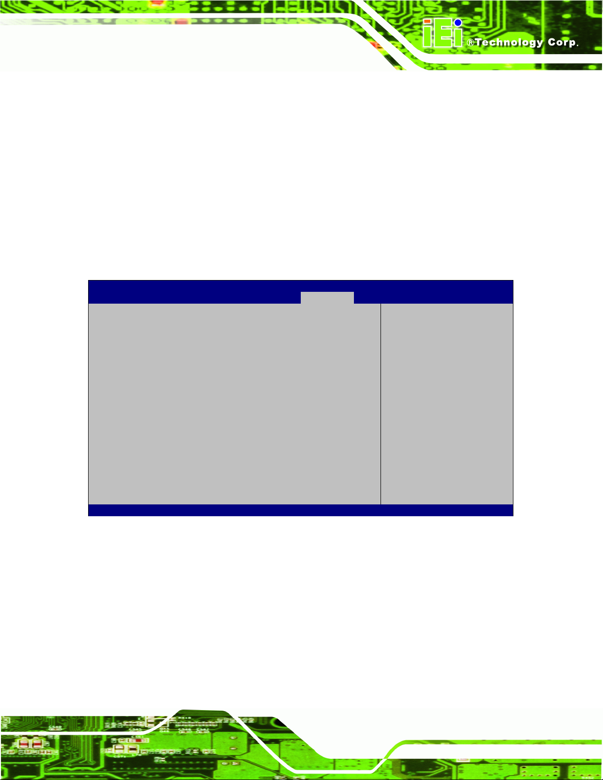
DRPC-100 Embedded System
Page 67
Force
BIOS
DEFAULT
Sets display mode to force BIOS.
Keep
Current
Sets display mode to current.
Aptio Setup Utility – Copyright (C) 2011 American Megatrends, Inc.
Main
Advanced
Chipset
Boot
Security
Save & Exit
Password Description
If ONLY the Administrator’s password is set,
then this only limits access to Setup and is
only asked for when entering Setup.
If ONLY the User’s password is set, then this
is a power on password and must be entered to
boot or enter Setup. In Setup the User will
have Administrator rights.
The password length must be
in the following range:
Minimum length 3
Maximum length 20
Administrator Password
User Password
Set Administrator
Password
---------------------
: Select Screen
: Select Item
Enter: Select
+/-: Change Opt.
F1: General Help
F2: Previous Values
F3: Optimized Defaults
F4: Save & Exit
ESC: Exit
Version 2.14.1219. Copyright (C) 2011 American Megatrends, Inc.
BIOS Menu 17: Security
Option ROM Messages [Force BIOS]
Use the Option ROM Messages option to set the Option ROM display mode.
5.6 Security
Use the Security menu (BIOS Menu 17) to set system and user passwords.
Administrator Password
Use the Administrator Password to set or change an administrator password.
User Password
Use the User Password to set or change a user password.
Page 82

DRPC-100 Embedded System
Page 68
Aptio Setup Utility – Copyright (C) 2011 American Megatrends, Inc.
Main
Advanced
Chipset
Boot
Security
Save & Exit
Save Changes and Reset
Discard Changes and Reset
Restore Defaults
Save as User Defaults
Restore User Defaults
Reset the system after
saving the changes.
---------------------
: Select Screen
: Select Item
Enter: Select
+/-: Change Opt.
F1: General Help
F2: Previous Values
F3: Optimized Defaults
F4: Save & Exit
ESC: Exit
Version 2.14.1219. Copyright (C) 2011 American Megatrends, Inc.
BIOS Menu 18: Save & Exit
5.7 Save & Exit
Use the Save & Exit menu (BIOS Menu 18) to load default BIOS values, optimal failsafe
values and to save configuration changes.
Save Changes and Reset
Use the Save Changes and Reset option to save the changes made to the BIOS options
and to exit the BIOS configuration setup program.
Discard Changes and Reset
Use the Discard Changes and Reset option to exit the system without saving the
changes made to the BIOS configuration setup program.
Restore Defaults
Use the Restore Defaults option to load the optimal default values for each of the
parameters on the Setup menus. F3 key can be used for this operation.
Page 83

DRPC-100 Embedded System
Page 69
Save as User Defaults
Use the Save as User Defaults option to save the changes done so far as user defaults.
Restore User Defaults
Use the Restore User Defaults option to restore the user defaults to all the setup options.
Page 84

DRPC-100 Embedded System
Page 70
Chapter
6
6 Programmable OLED Display
(DRPC-100-CV-OLED Only)
Page 85

DRPC-100 Embedded System
Page 71
6.1 Overview
The DRPC-100-CV-OLED comes with a programmable OLED display that allows users to
program their own APIs to show any information on it in graphic and text formats. The
driver CD includes two programs as below:
OLED Image Editor: Allows displaying information in graphic format.
DR100 Demo Program: Allows displaying information in text format.
The following sections will introduce these two programs.
6.2 OLED Image Editor
The OLED Image Editor allows displaying information in graphic format.
6.2.1 OLED Image Editor Installation
To install the OLED Image Editor, please follow the steps below.
Step 1: Insert the driver CD into an optical disk drive connected to the system.
Step 2: Locate the setup file in the OLEDImageEditor folder of the driver CD. Double
click the setup file to start the installation.
Step 3: The OLED Image Editor Setup Wizard welcome window appears (Figure 6-1).
Click Next to start.
Page 86

DRPC-100 Embedded System
Page 72
Figure 6-1: OLED Image Editor Setup Wizard
Figure 6-2: Select Installation Folder
Step 4: Select a folder for OLED Image Editor Installation in Figure 6-2. Click Next to
continue.
Page 87

DRPC-100 Embedded System
Page 73
Figure 6-3: Confirm Installation
Figure 6-4: Installation Complete
Step 5: The following screen appears. Click Next to confirm the installation.
Step 6: The system starts installing the OLED Image Editor.
Step 7: When the OLED Image Editor is successfully installed, the following window
appears. Click Close to exit. Step 0:
Page 88

DRPC-100 Embedded System
Page 74
Figure 6-5: OLED Image Editor
Figure 6-6: Function List
6.2.2 Launching the OLED Image Editor
To launch the OLED Image Editor, double click the OLED Image Editor icon on the
desktop.
6.2.3 Function List
The OLED Image Editor provides picture drawing function. Users can draw simple
pictures on the Canvas field.
Page 89
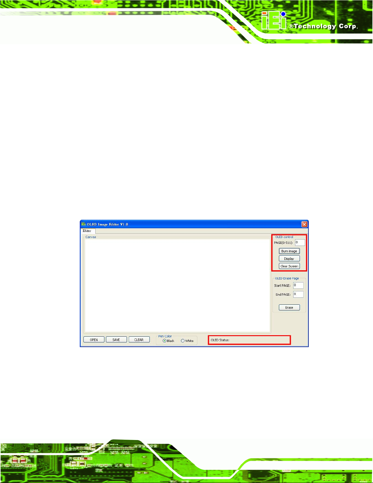
DRPC-100 Embedded System
Page 75
Figure 6-7: OLED Control
OPEN:
SAVE:
CLEAR:
Pen Color:
6.2.4 OLED Control
The OLED Control allows setup to the OLED module. Refer to the DRPC100-OLED
UART Protocol reference manual packaged in the driver CD for detailed setup.
Allows loading a 24-bit BMP file. The resolution of the 24-bit BMP file must be
128 x 64.
Allows saving as a BMP file. The file must be saved as 24-bit BMP with 128 x
64 resolution.
Clears the picture drew on the Canvas field.
Sets the pen color to black or white.
PAGE(0-511):
Allows users to indicate a page number to burn or display the image of the page
using the function buttons below it. The range of page number is 0 ~ 511.
Burn image:
Clicks to burn the image on the Canvas field into the OLED module according
Page 90

DRPC-100 Embedded System
Page 76
Figure 6-8: OLED Erase Page
Display:
Clear Screen:
6.2.5 OLED Erase Page
The OLED Erase Page allows erasing the images in the indicated page numbers. The
range of page number is 0 ~ 511. Besides, be noticed that the Start PAGE must be
smaller than the End Page.
to the indicated page number. When writing an image into the OLED module,
the OLED Status field displays “The page is under writing. Please wait…”.
Wait for several seconds. When finished, “Write Page Done” is displayed.
Clicks to show the corresponding image on the OLED display according to the
indicated page number.
Clicks to clear the OLED screen.
When the page number range is set, click Erase. A warning message will appear,
reminding users the estimated time. Click Yes to continue. The OLED Status field will
display the erasing status.
To erase all images, set the page number from 0 to 511.
Page 91
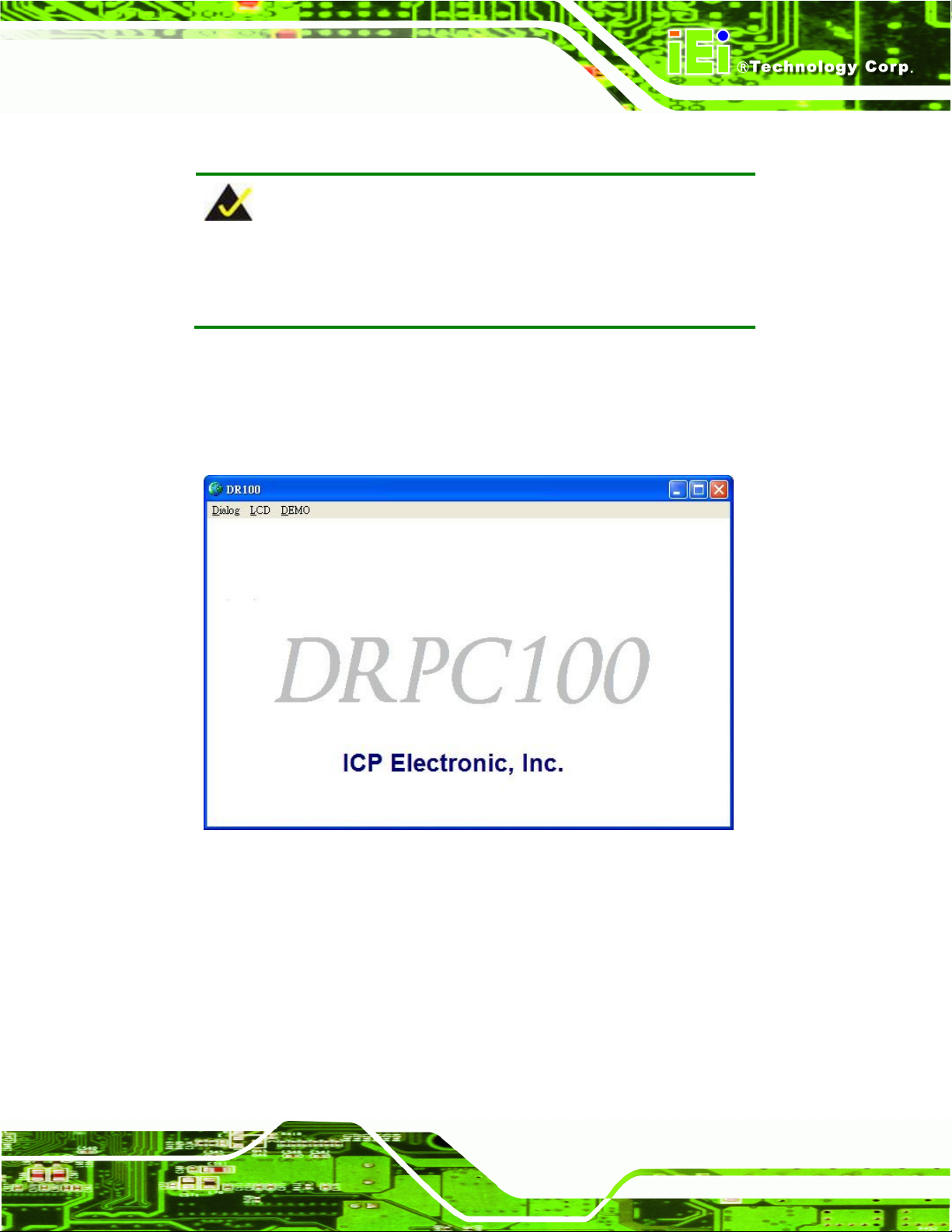
DRPC-100 Embedded System
Page 77
NOTE:
Refer to the DRPC100-Matrix LED UART Protocol reference manual
packaged in the driver CD for detailed setup.
Figure 6-9: DR100 Demo Program Main Menu
6.3 DRPC100 Demo Program
The DRPC100 Demo Program allows displaying information in text format.
To launch the DRPC100, double click the DRPC100_OLED_DEMO file located in the
DEMO APP folder of the driver CD. The main menu appears as below.
Page 92

DRPC-100 Embedded System
Page 78
Figure 6-10: Dialog Menu
6.3.1 Dialog Menu
The Dialog menu allows clearing the OLED screen and getting ID.
Get ID: Clicks to get ID.
Clr OLED: Clicks to clear the OLED screen.
Close: Clicks to return to the main menu.
Clear: Clears the messages.
Page 93

DRPC-100 Embedded System
Page 79
Figure 6-11: LCD Menu
6.3.2 LCD Menu
The LCD menu allows entering text to be displayed on the OLED display.
Send: Clicks to send the input text to be displayed on the OLED display.
Clear: Clears the input text.
Close: Clicks to return to the main menu.
Page 94

DRPC-100 Embedded System
Page 80
Figure 6-12: DEMO Menu
6.3.3 DEMO Menu
The DEMO menu lists the activities of the function keys. Click Close to return to the main
menu.
Page 95

DRPC-100 Embedded System
Page 81
Chapter
7
7 Interface Connectors
Page 96

DRPC-100 Embedded System
Page 82
Figure 7-1: Main Board Layout Diagram (Front Side)
Figure 7-2: Main Board Layout Diagram (Solder Side)
7.1 Peripheral Interface Connectors
The DRPC-100 embedded system motherboard comes with a number of peripheral
interface connectors and configuration jumpers. The connector locations are shown in
Figure 6-1 and Figure 6-2. The Pin 1 locations of the on-board connectors are also
indicated in the diagrams. The connector pinouts for these connectors are listed in the
following sections.
Page 97

DRPC-100 Embedded System
Page 83
Connector
Type
Label
Battery connector
2-pin wafer
CN1
Burn in CAN-bus firmware connector
8-pin header
CN4
Burn in MCU firmware connector
5-pin wafer
JP5
CompactFlash® card slot (solder
side)
CF slot
CF1
CPU Fan connector
3-pin wafer
CPU_FAN1
Indicator connector
6-pin wafer
F_PANEL1
OLED/LED signal connector
8-pin header
OLED1
PCIe Mini card slot (supports mSATA)
PCIe Mini card slot
M_PCIE1
SATA 3Gb/s connector
SATA connector
SATA1
SATA power connector
2-pin wafer
SATA_PWR1
SO-DIMM connector
SO-DIMM connector
DIMM1
SPI Flash connector
6-pin wafer
SPI1
Table 7-1: Peripheral Interface Connectors
PIN NO.
DESCRIPTION
1
VBATT
2
GND
Table 7-2: Battery Connector (CN1) Pinouts
7.2 Internal Peripheral Connectors
Internal peripheral connectors are found on the motherboard and are only accessible
when the motherboard is outside of the chassis. The table below shows a list of the
peripheral interface connectors on the DRPC-100 motherboard. Pinouts of these
connectors can be found in the following sections.
7.2.1 Battery Connector (CN1)
Page 98
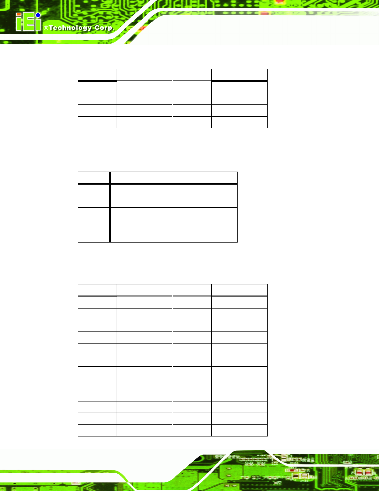
DRPC-100 Embedded System
Page 84
PIN NO.
DESCRIPTION
PIN NO.
DESCRIPTION
1
GND
5
NC 2 TDO
6
TMS 3 TDI 7 GND
4
NC 8 TCK
PIN NO.
DESCRIPTION
PIN NO.
DESCRIPTION
1
GROUND
26
S_IDE_Detect
2
S_D3
27
S_D11
3
S_D4
28
S_D12
4
S_D5
29
S_D13
5
S_D6
30
S_D14
6
S_D7
31
S_D15
7
S_DCS1#
32
S_DCS3#
8
GROUND
33
GROUND
9
GROUND
34
S_IOR#
10
GROUND
35
S_IOW#
11
GROUND
36
VCC_COM
12
GROUND
37
S_INT
Table 7-3: Burn in CAN-bus Firmware Connector (CN4) Pinouts
PIN NO.
DESCRIPTION
1
MCLR
2
+V5S
3
GND
4
ICSPDAT
5
ICSPCLK
Table 7-4: Burn in MCU Firmware (JP5) Pinouts
7.2.2 Burn in CAN-bus Firmware Connector (CN4)
7.2.3 Burn in MCU Firmware Connector (JP5)
7.2.4 CompactFlash® Card Slot (CF1)
Page 99

DRPC-100 Embedded System
Page 85
PIN NO.
DESCRIPTION
PIN NO.
DESCRIPTION
13
VCC_COM
38
VCC_COM
14
GROUND
39
M/S
15
GROUND
40
NC
16
GROUND
41
S_RST
17
GROUND
42
S_IORDY
18
S_DA2
43
S_DRQ
19
S_DA1
44
S_DACK#
20
S_DA0
45
SIDE_LED#
21
S_D0
46
S_PCBLID
22
S_D1
47
S_D8
23
S_D2
48
S_D9
24
NC
49
S_D10
25
CFD2
50
GROUND
Table 7-5: CompactFlash® Card Slot (CF1) Pinouts
PIN NO.
DESCRIPTION
1
CPUFANIN
2
+12V
3
GND
Table 7-6: CPU Fan Connector (CPU_FAN1) Pinouts
7.2.5 CPU Fan Connector (CPU_FAN1)
Page 100
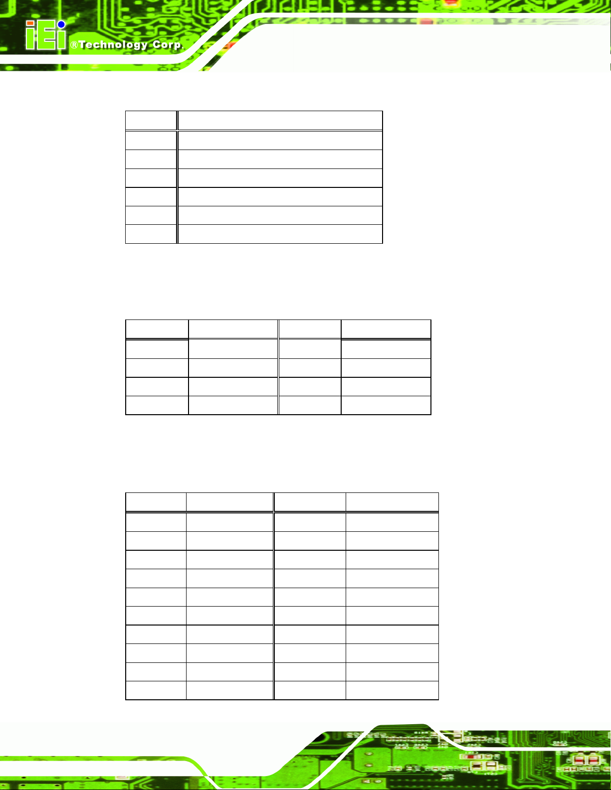
DRPC-100 Embedded System
Page 86
PIN NO.
DESCRIPTION
PIN NO.
DESCRIPTION
1
+3V
2
+12V
3
LED_SDA
4
GPIO
5
LED_SCL
6
GPIO
7
GND
8
RESET#
Table 7-8: OLED/LED Signal Connector (OLED1) Pinouts
PIN NO.
DESCRIPTION
PIN NO.
DESCRIPTION
1
PCIE_WAKE#
2
VCC3
3
N/C 4 GND
5
N/C 6 1.5V
7
N/C 8 N/C 9 GND
10
N/C
11
CLK-
12
N/C
13
CLK+
14
N/C
15
GND
16
N/C
17
PCIRST#
18
GND
19
N/C
20
VCC3
PIN NO.
DESCRIPTION
1
VCC 2 GND
3
PWR_LED+
3
PWR_LED-
5
HDD_LED+
6
HDD_LED-
Table 7-7: Indicator Connector (F_PANEL1) Pinouts
7.2.6 Indicator Connector (F_PANEL1)
7.2.7 OLED/LED Signal Connector (OLED1)
7.2.8 PCIe Mini Card Slot (M_PCIE1)
 Loading...