

Page 1
AUPS Series Power Module User Manual
Page i
Model:
AUPS Series
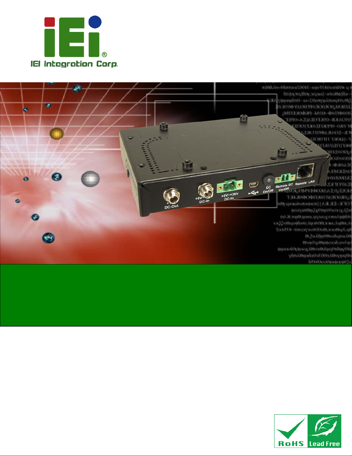
VESA Mount Intelligent UPS Module
Rev. 2.00 – July 3, 2018
12 V DC Input or 9 V–36 V DC Input
Network Remote Management Support
User Manual
Page 2

AUPS Series Power Module User Manual
Page ii
Revision
Date Version Changes
July 3, 2018 2.00 Updated for R20 version:
-Battery Specifications
-Chapter 4: Software Application
May 7, 2014 1.01 Added Appendix A: Safety Precautions
November 12, 2008 1.00 Initial release
Page 3

AUPS Series Power Module User Manual
Page iii
Copyright
COPYRIGHT NOTICE
The information in this document is subject to change without prior notice in order to
improve reliability, design and function and does not represent a commitment on the part
of the manufacturer.
In no event will the manufacturer be liable for direct, indirect, special, incidental, or
consequential damages arising out of the use or inability to use the product or
documentation, even if advised of the possibil ity of such damages.
This document contains proprietary information protected by copyright. All rights are
reserved. No part of this manual may be reproduced by any mechanical, electronic, or
other means in any form without prior written permission of the manufacturer.
TRADEMARKS
All registered trademarks and product names mentioned herein are used for identification
purposes only and may be trademarks and/or registered trademarks of their respective
owners.
Page 4
AUPS Series Power Module User Manual
Page iv
Manual Conventions
WARNING
Warnings appear where overlooked details may cause damage to the
equipment or result in personal injury. Warnings should be t aken
seriously.
CAUTION
Cautionary messages should be heeded to help red uce the chance of
losing data or damaging the product.
NOTE
These messages inform the reader of essenti al but non-critical
information. These messages should be read carefully as any directions
or instructions contained therein can help avoid making mistakes.
HOT SURFACE
This symbol indicates a hot surface that shoul d not be touched without
taking care.
Page 5

AUPS Series Power Module User Manual
Page v
Table of Contents
1 INTRODUCTION .......................................................................................................... 1
1.1 AUPS SERIES OVERVIEW ........................................................................................... 2
1.2 AUPS SERIES UPS MODULE FEATURES ..................................................................... 2
1.3 EXTERNAL OVERVIEW ................................................................................................ 3
1.3.1 I/O interface panel (Standard) ........................................................................... 3
1.3.1.1 AUPS-A10 Power Input Connector ............................................................ 4
1.3.1.2 AUPS-A20 Power Input Connectors .......................................................... 4
1.3.1.3 AUPS-B10 Power Input Connector ............................................................ 5
1.3.1.4 AUPS-B20 Power Input Connectors ........................................................... 5
1.3.2 LED Indicators ................................................................................................... 6
1.4 AUPS SERIES SPECIFICATIONS ................................................................................... 7
1.5 BATTERY SPECIFICATIONS .......................................................................................... 8
1.5.1 AUPS-A10/AUPS-A20 Battery ........................................................................... 8
1.5.2 AUPS-B10/AUPS-B20 Battery ......................................................................... 10
1.6 AUPS SERIES DIMENSIONS ...................................................................................... 12
1.6.1 AUPS-A10/AUPS-A20 Dimensions .................................................................. 12
1.6.2 AUPS-B10/AUPS-B20 Dimensions .................................................................. 13
2 UNPACKING ............................................................................................................... 14
2.1 ANTI-STATIC PRECAUTIONS ...................................................................................... 15
2.2 UNPACKING .............................................................................................................. 15
2.2.1 Unpacking Precautions .................................................................................... 15
2.3 UNPACKING CHECKLIST ........................................................................................... 16
2.3.1 Package Contents ............................................................................................. 16
3 INSTALLATION ......................................................................................................... 18
3.1 ANTI-STATIC PRECAUTIONS ...................................................................................... 19
3.2 INSTALLATION PRECAUTIONS ................................................................................... 19
3.3 INSTALLATION AND CONFIGURATION STEPS ............................................................. 20
3.4 BATTERY PACK INSTALLATION ................................................................................. 20
3.5 MOUNTING THE AUPS SERIES ................................................................................. 21
Page 6

AUPS Series Power Module User Manual
Page vi
3.6 CONNECTING THE AUPS SERIES .............................................................................. 23
4 SOFTW ARE APPLICA TION ..................................................................................... 24
4.1 INTRODUCTION ......................................................................................................... 25
4.2 DRIVER INSTALLATION ............................................................................................. 25
4.3 APPLICATION INSTALLATION .................................................................................... 29
4.4 MONITORING DC POWER AND SMART BATTERY ...................................................... 31
4.4.1 Status Information ............................................................................................ 31
4.4.1.1 DC Power Status ....................................................................................... 31
4.4.1.2 Battery Status ............................................................................................ 32
4.4.2 Battery Information .......................................................................................... 33
4.4.3 LAN Setting ...................................................................................................... 34
4.4.3.1 Using Static IP .......................................................................................... 35
4.4.4 Setting .............................................................................................................. 36
4.4.5 E-mail ............................................................................................................... 37
4.5 REMOTE CONTROL AND MONITORING ...................................................................... 38
A SAFETY PRECAUTIONS ......................................................................................... 43
B HAZARDOUS MATERIALS DISCLOSURE ......................................................... 49
Page 7

AUPS Series Power Module User Manual
Page vii
List of Figures
Figure 1-1: AUPS Series UPS Module .......................................................................................... 2
Figure 1-2: AUPS Series Standard I/O Interface Connectors ..................................................... 3
Figure 1-3: AUPS-A10 Power Input Connector ............................................................................ 4
Figure 1-4: AUPS-A20 Power Input Connectors .......................................................................... 4
Figure 1-5: AUPS-B10 Power Input Connector ............................................................................ 5
Figure 1-6: AUPS-B20 Power Input Connectors .......................................................................... 5
Figure 1-7: AUPS Series LED Indicators ...................................................................................... 6
Figure 1-8: AUPS-A10/A20 Dimensions (mm) ........................................................................... 12
Figure 1-9: AUPS-B10/B20 Dimensions (mm) ........................................................................... 13
Figure 3-1: Top Cover Retention Screws (Rear Panel) ............................................................. 20
Figure 3-2: Top Cover Retention Screws (Top Panel) .............................................................. 21
Figure 3-3: Battery Pack Installation .......................................................................................... 21
Figure 3-4: Mounting Bracket Installation .................................................................................. 22
Figure 3-5: Mounting the AUPS Series ....................................................................................... 22
Figure 3-6: AUPS Series and Panel PC Connection ................................................................. 23
Figure 4-1: Preparing Setup Screen ........................................................................................... 25
Figure 4-2: Driver Welcome Screen ............................................................................................ 26
Figure 4-3: Driver License Agreement Screen .......................................................................... 26
Figure 4-4: Choose Destination Location .................................................................................. 27
Figure 4-5: Ready to Install the Driver ........................................................................................ 27
Figure 4-6: InstallShield Wizard Complete Screen .................................................................... 28
Figure 4-7: CP210x USB to UART Bridge Driver In staller ........................................................ 28
Figure 4-8: Installation Complete ................................................................................................ 28
Figure 4-9: Welcome Screen ....................................................................................................... 29
Figure 4-10: Installation Complete .............................................................................................. 30
Figure 4-11: IEI AUPS Application Overview ............................................................................. 30
Figure 4-12: Status Information .................................................................................................. 31
Figure 4-13: DC Detection ............................................................................................................ 31
Figure 4-14: Battery Information ................................................................................................. 33
Figure 4-15: LAN Setting .............................................................................................................. 34
Page 8

AUPS Series Power Module User Manual
Page viii
Figure 4-16: LAN Setting – Disable DHCP ................................................................................. 35
Figure 4-17: Application Setting ................................................................................................. 36
Figure 4-18: E-mail Setting .......................................................................................................... 37
Figure 4-19: RJ-45 Remote LAN Connector ............................................................................... 38
Figure 4-20: Remote AP ............................................................................................................... 39
Figure 4-21: Remote AP – IP Address ........................................................................................ 39
Figure 4-22: Remote Management Web Interface - Status ....................................................... 40
Figure 4-23: Remote Management Web Interface - Send Email .............................................. 40
Figure 4-24: Enter User Name and Password ............................................................................ 41
Figure 4-25: Remote Management Web Interface - Configuration ........................................ 42
Page 9

AUPS Series Power Module User Manual
Page ix
List of Tables
Table 1-1: LED Indicators .............................................................................................................. 6
Table 1-2: AUPS Series Specifications......................................................................................... 7
Table 1-3: AUPS-A10/AUPS-A20 Battery Specifications ............................................................ 9
Table 1-4: AUPS-B10/AUPS-B20 Battery Specifications .......................................................... 11
Table 2-1: Package List Contents ............................................................................................... 17
Page 10

Page 11

AUPS Series Power Module User Manual
Page 1
Chapter
1
1 Introduction
Page 12

AUPS Series Power Module User Manual
Page 2
1.1 AUPS Series Overview
Figure 1-1: AUPS Series UPS Module
The highly efficient, high-performance AUPS Series UPS (Uninterruptible Power Supply)
module installed with a Li-ion battery to provide stable 12 V output and uninterruptible
power to the IEI AFOLUX series panel PCs. The UPS module also receives either 12 V
input or a wide range of inputs between 6 V and 36 V DC. The AUPS Series is built on an
intelligent design and provides outstanding line and load regulations. The AUPS Series is
capable of providing power for certain of time in power failure.
The AUPS Series UPS module comes with the utility software that provides information on
current power source and battery status. With the AUPS software installed and network
connected, the AUPS Series can be monitored and turned on/off through a remote
computer.
1.2 AUPS Series UPS Module Features
Rugged metal enclosure for standard VESA 75/100 mounting
Wide range power input (9 V–36 V) by DC jack or term i nal bl ock
Network management through web-based interface i n remote computer. No
additional administration software install ation is required.
Supports PC-based utility for monitoring power and battery status
Auto shut down when battery low
Provides stable power to AFOLUX PPC during line sags and spikes.
Absorb power surges and transients
Page 13

AUPS Series Power Module User Manual
Page 3
1.3 External Overview
1.3.1 I/O interface panel (Standard)
The I/O interface panel of the AUPS Series (see Figure 1-2) has the following standard
I/O interface connectors:
1 x 12 V DC output jack
1 x USB mini-B connector
1 x Network remote management port (RJ-45)
1 x DC output switch terminal block
1 x DC on/off button
The standard external I/O interface connector panel is shown in Figure 1-2.
Figure 1-2: AUPS Series Standard I/O Interface Connectors
Page 14

AUPS Series Power Module User Manual
Page 4
1.3.1.1 AUPS-A10 Power Input Connector
The AUPS-A10 has one power jack for +12 V DC input (Figure 1-3).
Figure 1-3: AUPS-A10 Power Input Connector
1.3.1.2 AUPS-A20 Power Input Connectors
The AUPS-A20 has one power jack and one terminal block for 9 V–36 V DC inputs
(Figure 1-4).
Figure 1-4: AUPS-A20 Power Input Connectors
Page 15

AUPS Series Power Module User Manual
Page 5
1.3.1.3 AUPS-B10 Power Input Connector
The AUPS-B10 has one 4-pin power connector for +12 V DC inpu t (Figure 1-5).
Figure 1-5: AUPS-B10 Power Input Connector
1.3.1.4 AUPS-B20 Power Input Connectors
The AUPS-B20 has one 4-pin power connector and one terminal block for 9 V–36 V DC
inputs (Figure 1-6).
Figure 1-6: AUPS-B20 Power Input Connectors
Page 16

AUPS Series Power Module User Manual
Page 6
1.3.2 LED Indicators
The side panel of the AUPS Serie s has three LED indicators to indicate the power and
battery status (Figure 1-7).
Figure 1-7: AUPS Series LED Indicators
All the LED statuses are listed in Table 1-1.
Color
Off
On
Blinking
Table 1-1: LED Indicators
Power Input LED
Green Yellow Orange
DC power out -- -DC power in Discharging (battery full) Battery discharging
-- Charging Battery low
Charger Status LED Battery Status LED
Page 17

AUPS Series Power Module User Manual
Page 7
1.4 AUPS Series Specifications
The AUPS Series UPS module technical specifications are list ed in Table 1-2.
Model Name AUPS-A10 AUPS-A20 AUPS-B10 AUPS-B20
VESA Type VESA 75 mm x 75 mm VESA 75 mm x 75 mm
VESA 100 mm x 100 mm
Output Voltage +12 V +/-5% +12 V +/-5% +12 V +/-5% +12 V +/-5%
Power 60 W 60 W 100 W 100 W
Input Voltage +12 V +9 V ~ +36 V +12 V +9 V ~ +36 V
Battery Type Li-ion 2S2P Li-ion 2S2P Li-ion 4S2P Li-ion 4S2P
Nominal
Voltage
Nominal
Capacity
Physical Dimensions
(LxWxH)
Weight 1.2 kg 1.2 kg 1.8 kg 1.8 kg
LED Green DC power input DC power input DC power input DC power input
Yellow Battery charging Battery charging Battery charging Battery charging
Orange Battery discharging Battery discharging Battery discharging Battery discharging
Temperature Operating
Storage
7.26 V
5200 mAh 5200 mAh 5200 mAh 5200 mAh
150 x 95 x 34 (mm) 150 x 95 x 34 (mm) 170 x 150 x 34
0°C ~ 40°C 0°C ~ 40°C 0°C ~ 40°C 0°C ~ 40°C
-20°C ~ 50°C -20°C ~ 50°C -20°C ~ 50°C -20°C ~ 50°C
7.26 V
14.52 V
(mm)
14.52 V
170 x 150 x 34
(mm)
Table 1-2: AUPS Series Specifications
Page 18

AUPS Series Power Module User Manual
Page 8
C,
C,
C,
e
1.5 Battery Specifications
The AUPS Series comes with a Li-ion smart battery. Some of the Li-ion battery
specifications are listed in the following tabl es.
1.5.1 AUPS-A10/AUPS-A20 Battery
Specifications Remarks
AUPS Model
Battery Pack
Battery Type
Nominal Capacity
Minimum Capacity
Nominal Voltage
End of Discharge Voltage
Charge Voltage
Rated Charge Current
AUPS-A10/AUPS-A20 -4 cells 2S2P
Li-ion --
0.5C charge/0.2C discharge at 25±3°
5200 mAh
cut off voltage at 2.75 V/cell
0.5C charge/0.2C discharge at 25±3°
5000 mAh
cut off voltage at 2.75 V/cell
0.5C charge/0.2C discharge at 25±3°
7.26 V
cut off voltage at 2.75 V/cell
5.5 V FD set 5.5 V
0~10°C 11~45°C 46~60°C
Charging Voltage 8400 mV 8400 mV 8200 mV
0~10°C 11~45°C 46~60°C
Per cell≦2.75V
2.75V≦Per cell≦4.1V
4.1V≦Per cell≦4.2V
Pre-charge Current
510 mA (cell < 2.75 V)
Max. Continuous Discharge
50 W
Power
Max. Continuous Discharg
7.5 A
Current
510 mA 510 mA 510 mA
1530 mA 2550 mA 2550 mA
1530 mA 2550 mA 0 mA
Gas-gauge reports charge current as
510 mA
Environment temp.: 0~40°C
Discharge from 100% to 0%
Environment temp.: 0~40°C
Discharge from 100% to 0%
Page 19

AUPS Series Power Module User Manual
Page 9
Max. Discharge Current
Pack Operating Temp.
Storage Temperature
Protection
Over Voltage Protection
Under Voltage Protection
Cell Shutdown Voltage
Protection
Over Discharge Current
Protection (SW)
9.36 A Duration time < 5 sec.
0~40°C Max. Humidity: 85% RH
1 year: -20°C ~ +25°C
During storage, pack must be charged
3 months: -20°C ~ +45°C
to 40%~50% every 3 months.
1 month: -20°C ~ +65°C
Set: ≧4.24±0.02V / cell (0°C ~ 45°C), delay time: 2~4 sec.
Reset: <4.10±0.02V / cell
Set: ≧2.55±0.02V / cell, delay time: 2~4 sec.
Reset:≧2.75±0.02V / cell
Cell ≦2.35V, delay time: 30 sec.
Set: ≧10.04A, delay time 5~7 sec.
Reset: Current > -20mA, then 30 sec.
Over Discharge Current
Protection (AFE)
Short-circuit Protection
Over Charge Current
Protection
Charge Over Temperature
Protection
Discharge Over
Temperature Protection
Table 1-3: AUPS-A10/AUPS-A20 Battery Specifications
Set: 11.5~14.5A, typical 12.95A, delay time 31±4 mSec
Reset: after 30 sec, and then current < 5mA
Set: ≧30±20%A, delay time: 700uSec~1200uSec, typical 916uSec
Reset: after 30sec, and then current < 5mA
Set: ≧5.2A, delay time 2~4 sec.
Reset: Current < 20mA, then 30 sec.
Set: ≧60±3ºC, delay time: 2~4 sec
Reset: <45±3ºC
Set: ≧70±3ºC, delay time: 2~4 sec
Reset: <60±3ºC
Page 20

AUPS Series Power Module User Manual
Page 10
C,
C,
C,
e
1.5.2 AUPS-B10/AUPS-B20 Battery
Specifications Remarks
AUPS Model
Battery Pack
Battery Type
Nominal Capacity
Minimum Capacity
Nominal Voltage
End of Discharge Voltage
Charge Voltage
Rated Charge Current
AUPS-B10/AUPS-B20 -8 cells 4S2P
Li-ion --
0.5C charge/0.2C discharge at 25±3°
5200 mAh
cut off voltage at 2.75 V/cell
0.5C charge/0.2C discharge at 25±3°
5000 mAh
cut off voltage at 2.75 V/cell
0.5C charge/0.2C discharge at 25±3°
14.52 V
cut off voltage at 2.75 V/cell
11 V FD set 11 V
0~10°C 11~45°C 46~60°C
Charging Voltage 16800 mV 16800 mV 16400 mV
0~10°C 11~45°C 46~60°C
Pre-charge Current
Max. Continuous Discharge
Power
Max. Continuous Discharg
Current
Max. Discharge Current
Pack Operating Temp.
Per cell≦2.75V
2.75V≦Per cell≦4.1V
4.1V≦Per cell≦4.2V
510 mA 510 mA 510 mA
1530 mA 2550 mA 2550 mA
1530 mA 2550 mA 0 mA
Gas-gauge reports charge current as
510 mA (cell < 2.75 V)
510 mA
Environment temp.: 0~40°C
100 W
Discharge from 100% to 0%
Environment temp.: 0~40°C
7.5 A
Discharge from 100% to 0%
9.36 A Duration time < 5 sec.
0~40°C Max. Humidity: 85% RH
Page 21

AUPS Series Power Module User Manual
Page 11
Storage Temperature
Protection
Over Voltage Protection
Under Voltage Protection
Cell Shutdown Voltage
Protection
Over Discharge Current
Protection (SW)
Over Discharge Current
Protection (AFE)
1 year: -20°C ~ +25°C
During storage, pack must be charged
3 months: -20°C ~ +45°C
to 40%~50% every 3 months.
1 month: -20°C ~ +65°C
Set: ≧4.24±0.02V / cell (0°C ~ 45°C), delay time: 2~4 sec.
Reset: <4.10±0.02V / cell
Set: ≧2.55±0.02V / cell, delay time: 2~4 sec.
Reset:≧2.75±0.02V / cell
Cell ≦2.35V, delay time: 30 sec.
Set: ≧10.04A, delay time 5~7 sec.
Reset: Current > -20mA, then 30 sec.
Set: 11.5~14.5A, typical 12.95A, delay time 31±4 mSec
Reset: after 30 sec, and then current < 5mA
Short-circuit Protection
Over Charge Current
Protection
Charge Over Temperature
Protection
Discharge Over
Temperature Protection
Table 1-4: AUPS-B10/AUPS-B20 Battery Specifications
Set: ≧30±20%A, delay time: 700uSec~1200uSec, typical 916uSec
Reset: after 30sec, and then current < 5mA
Set: ≧5.2A, delay time 2~4 sec.
Reset: Current < 20mA, then 30 sec.
Set: ≧60±3ºC, delay time: 2~4 sec
Reset: <45±3ºC
Set: ≧70±3ºC, delay time: 2~4 sec
Reset: <60±3ºC
Page 22

AUPS Series Power Module User Manual
Page 12
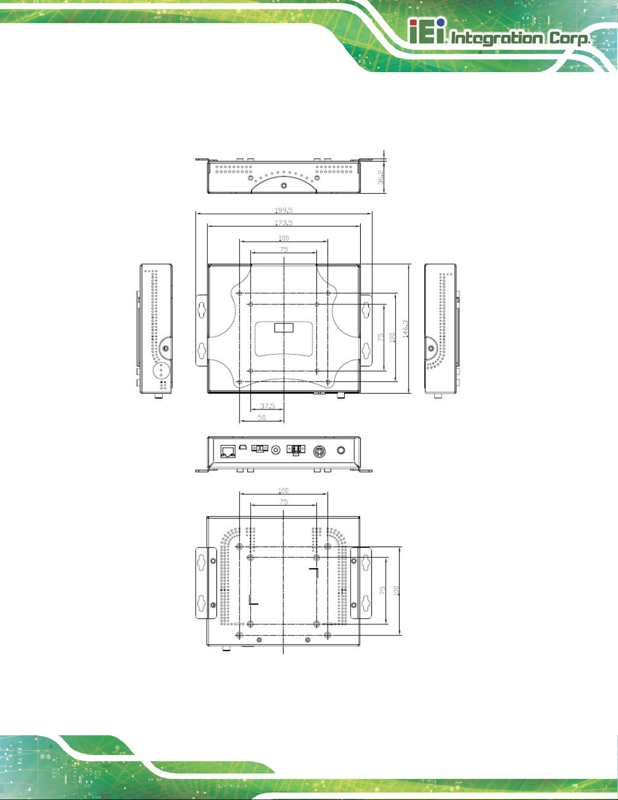
1.6 AUPS Series Dimensions
1.6.1 AUPS-A10/AUPS-A20 Dimensions
The AUPS-A10 and AUPS-A20 dimensions are shown in Figure 1-8.
Figure 1-8: AUPS-A10/A20 Dimensions (mm)
Page 23
AUPS Series Power Module User Manual
Page 13
1.6.2 AUPS-B10/AUPS-B20 Dimensions
The AUPS-B10 and AUPS-B20 dimensions are shown in Figure 1-8.
Figure 1-9: AUPS-B10/B20 Dimensions (mm)
Page 24

AUPS Series Power Module User Manual
Page 14
Chapter
2
2 Unpacking
Page 25

AUPS Series Power Module User Manual
Page 15
2.1 Anti-static Precautions
WARNING:
Failure to take ESD precautions during the installation of the AUPS
Series may result in permanent damage to the AUPS Series and
severe injury to the user.
Electrostatic discharge (ESD) can cause serious damage to electronic components,
including the AUPS Series. Dry climates are especially susceptible to ESD. It is therefore
critical that whenever the AUPS Series, or any other electrical component is handled, the
following anti-static precautions are strictly adhered to.
Wear an anti-static wristband: Wearing a simple anti-static wristband can
help to prevent ESD from damaging the board.
Self-grounding: Before handling the board touch any grounded conducting
material. During the time the board is handled, f requently touch any
conducting materials that are connected to the ground.
Use an anti-static pad: When configuring the AUPS Series, place it on an
antic-static pad. This reduces the possibility of ESD damaging the AUPS
Series.
Only handle the edges of the PCB: When handling the PCB, hol d the PCB
by the edges.
2.2 Unpacking
2.2.1 Unpacking Precautions
When the AUPS Series is unpacked, please do the following:
Follow the anti-static precautions outline d i n Section 2.1.
Make sure the packing box is facing upwards so t he AUPS Series does not
fall out of the box.
Make sure all the components shown in Section 2.3 are present.
Page 26

AUPS Series Power Module User Manual
Page 16
If some of the components listed in the checklist below are missing,
2.3 Unpacking Checklist
NOTE:
please do not proceed with the installation. Contact the IEI reseller or
vendor you purchased the AUPS Series from or contact an IEI sales
representative directly. To contact an IEI sales representative, please
send an email to
sales@ieiworld.com.tw.
2.3.1 Package Contents
The AUPS Series is shipped with the following components:
Quantity Item Image
1 AUPS Series UPS module
1 Li-ion battery pack
1 Mounting bracket
1 DC output cable
1 DC output switch cable
Page 27

AUPS Series Power Module User Manual
Page 17
1 USB Type A to mini-B cable
1 Screw kit
2 Wall mount bracket
Table 2-1: Package List Contents
Page 28

AUPS Series Power Module User Manual
Page 18
Chapter
3
3 Installation
Page 29

AUPS Series Power Module User Manual
Page 19
3.1 Anti-static Precautions
WARNING:
Failure to take ESD precautions during the maintenance of the AUPS
Series may result in permanent damage to the AUPS Series and
severe injury to the user.
Electrostatic discharge (ESD) can cause serious damage to electronic components,
including the AUPS Series. Dry climates are especially susceptible to ESD. It is therefore
critical that whenever the AUPS Series is accessed internally, or any other electrical
component is handled, the following anti-stat i c precautions are strictly adhered to.
Wear an anti-static wristband: - Wearing a simple anti-static wristband can
help to prevent ESD from damaging the board.
Self-grounding: - Before handling the board touch any grounded conducting
material. During the time the board is handled, f requently touch any
conducting materials that are connected to the ground.
Use an anti-static pad: - When configuring the AUPS Series, place it on an
antic-static pad. This reduces the possibility of ESD damaging the AUPS
Series.
Only handle the edges of the PCB: - When handling the PCB, hold the PCB
by the edges.
3.2 Installation Precautions
When installing the power module, please follow the precautions listed below:
Power turned off: When installing the power module, make su re the power is
off. Failing to turn of f the power may cause severe injury to the body and/or
damage to the system.
Certified Engineers: Only certified engineers should install and modify
onboard functionalities.
Page 30

AUPS Series Power Module User Manual
Page 20
Anti-static Discharge: If a user open the top cover of the power module, to
configure the jumpers or plug in added peripheral dev ices, ground themselves
first and wear and anti-static wristband.
3.3 Installation and Configuration Steps
The following installation steps must be foll owed.
Step 1: Unpack the UPS module
Step 2: Install the battery pack
Step 3: Mount UPS module to the AFOLUX panel PC
Step 4: Connect the UPS module to the AFOLUX panel PC Step 0:
3.4 Battery Pack Installation
The battery pack must be installed to enable the UPS module. To install the battery pack,
follow the steps below.
Step 1: Remove the four top cover retention screws (Figure 3-1 and Figure 3-2) and lift
the top cover off the AUPS Series module.
Figure 3-1: Top Cover Retention Screws (Rear Panel)
Page 31

AUPS Series Power Module User Manual
Page 21
Figure 3-2: Top Cover Retention Screws (Top Panel)
Step 2: Install the battery pack into the AUPS Series. Make sure the battery pack is
connected to the battery connector on the board. (Figure 3-3)
Figure 3-3: Battery Pack Installation
Step 3: Secure the battery pack with two retention screws.
Step 4: Replace the top cover. Step 0:
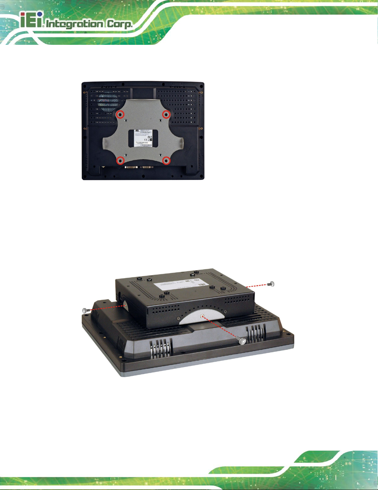
3.5 Mounting the AUPS Series
To mount the AUPS Series onto the rear panel of the AFOLUX panel PC, follow the steps
below.
Step 1: Install the mounting bracket onto the rear panel of the AFL panel PC. Align
the screw holes in the mounting bracket wit h the VESA screw holes in the rear of
Page 32
AUPS Series Power Module User Manual
Page 22
the panel PC. Secure the mounting bracket to t he panel P C with four retention
screws (Figure 3-4).
Figure 3-4: Mounting Bracket Installation
Step 2: Place the AUPS Series onto the mounting bracket. Secure the AUPS Series
to the bracket with three retention screws, one on the t op panel and one on e ach
side panel (Figure 3-5).
Figure 3-5: Mounting the AUPS Series
Page 33

AUPS Series Power Module User Manual
Page 23
3.6 Connecting the AUPS Series
To support the UPS function to the panel PC, the AUPS Series must be connected to the
power source and to the panel PC. Figure 3-6 sho ws the connections.
Figure 3-6: AUPS Series and Panel PC Connection
Page 34

AUPS Series Power Module User Manual
Page 24
Chapter
4
4 Software Application
Page 35

AUPS Series Power Module User Manual
Page 25
4.1 Introduction
The IEI AUPS application detects the information of the smart battery and monitors the
battery status. It is recommended to execute this AUPS application in Windows 7 or
above.
4.2 Driver Installation
Follow the steps below to install the necessary drivers.
Step 1: Download AUPS driver from IEI website.
Step 2: Run the CP210x_VCP_Win2K_XP_S2K3.exe file. The InstallShield Wizard
prepares the setup as shown (Figure 4-1).
Figure 4-1: Preparing Setup Screen
Page 36

AUPS Series Power Module User Manual
Page 26
Step 3: A welcome screen appears (Figure 4-2). To continue the installation process
click Next.
Figure 4-2: Driver Welcome Screen
Step 4: The license agreement in Figure 4-3 appears. R ead the License Agreement.
Check I accept the terms of license agreement and click Next to continue.
Figure 4-3: Driver License Agreement Screen
Page 37
AUPS Series Power Module User Manual
Page 27
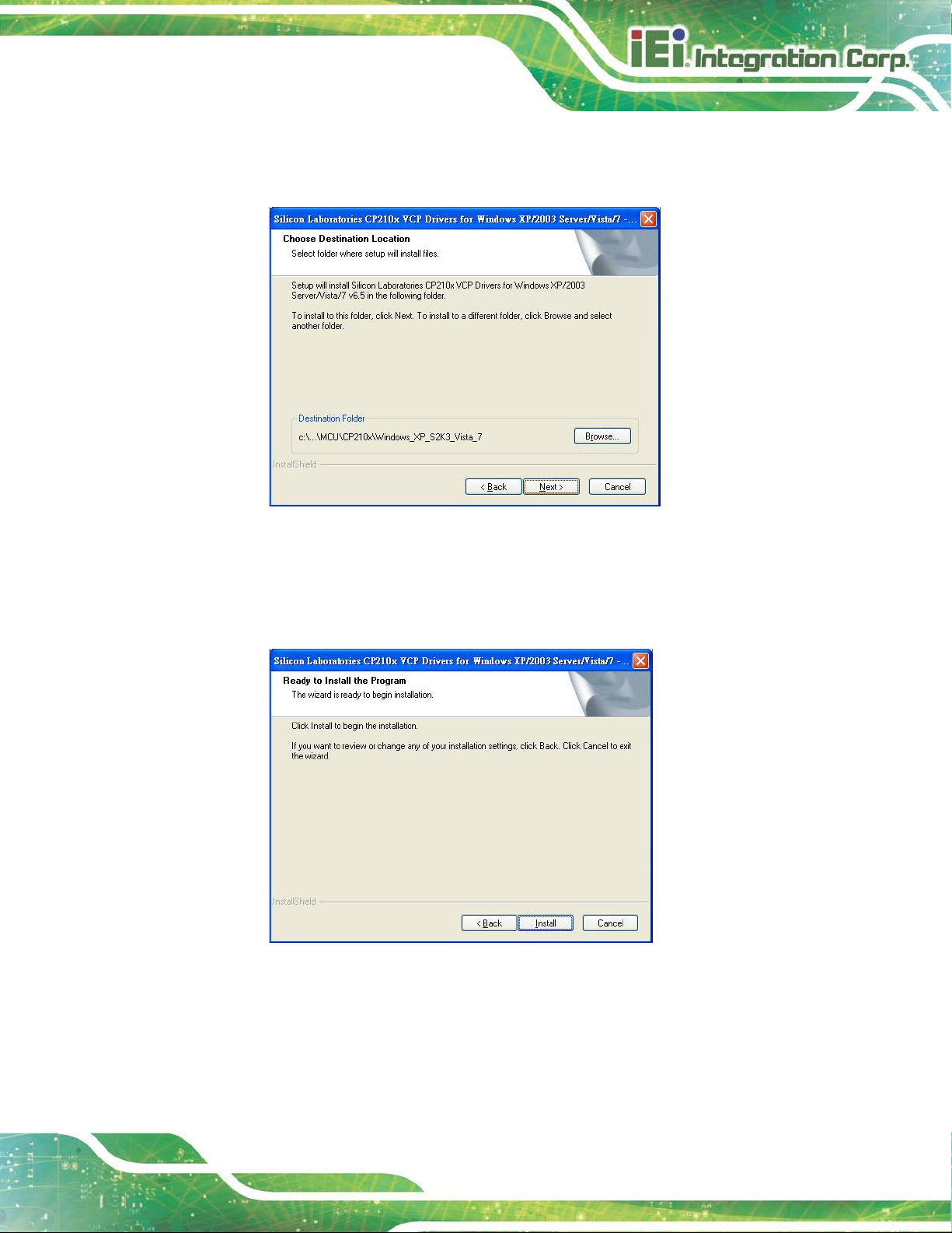
Step 5: The Choose Destination Location window appears (Figure 4-4). Select a
folder to install the driver.
Figure 4-4: Choose Destination Location
Step 6: Click Next and the InstallShield Wizard is ready to install the driv er (Figure 4-5).
Step 7: Click Install to start the installation.
Figure 4-5: Ready to Install the Driver
Page 38
AUPS Series Power Module User Manual
Page 28
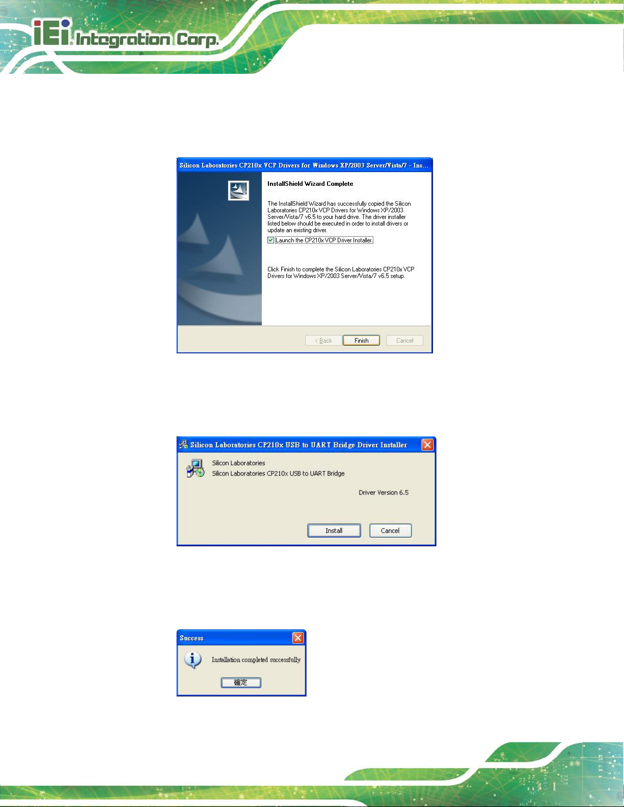
Step 8: The InstallShield Wizard Complete window ap pears (Figure 4-6). Check
Launch the CP210x VCP Driver Installer and click Finish to launch the
CP210x USB to UART Bridge Driver Installer.
Figure 4-6: InstallShield Wizard Complete Screen
Step 9: Click Install to start installing the CP210x USB to UART Bridge driver
(Figure 4-7).
Figure 4-7: CP210x USB to UART Bridge Driver Installer
Step 10: When the installation is complete, the screen in Figure 4-8 appears. Click
Finish to exit.
Figure 4-8: Installation Complete
Page 39

AUPS Series Power Module User Manual
Page 29
4.3 Application Installation
Follow the steps below to install the AUPS application.
Step 1: Download the AUPS setup file from IEI website. Run the
AUPS_SetupV100A.exe file.
Step 2: A welcome screen appears (Figure 4-9). To continue the installation process
click Install.
Figure 4-9: Welcome Screen
Step 3: The Setup Wizard starts installing the program.
Step 4: The Installation Complete window appears (Figure 4-10). Click Finish to exit.
Page 40

AUPS Series Power Module User Manual
Page 30
Figure 4-10: Installation Complete
Step 5: To launch the application, double click the shortcut (Figure 4-11) on the desktop.
Figure 4-11: IEI AUPS Application Overview
Page 41

AUPS Series Power Module User Manual
Page 31
4.4 Monitoring DC Power and Smart Batt ery
4.4.1 Status Information
The STATUS page of IEI AUPS appli cation sho ws the DC po wer sta tus and batte ry status
(Figure 4-12). The following sections describe the status information in details.
Figure 4-12: Status Information
4.4.1.1 DC Power Status
When the DC power is connected to the AUPS series power module, the AUPS
application detects it and shows in the screen as Figure 4-13.
Figure 4-13: DC Detection
Page 42

AUPS Series Power Module User Manual
Page 32
4.4.1.2 Battery Status
The AUPS application detects the smart battery installed in the AUPS series power
module and shows the battery status in the s creen.
Capacity Current battery capacity.
Using The battery is being used.
Charging The battery is being charged.
Standby The battery is fully charged and ready to be used anytime.
Temperature Current battery temperature.
Page 43
AUPS Series Power Module User Manual
Page 33
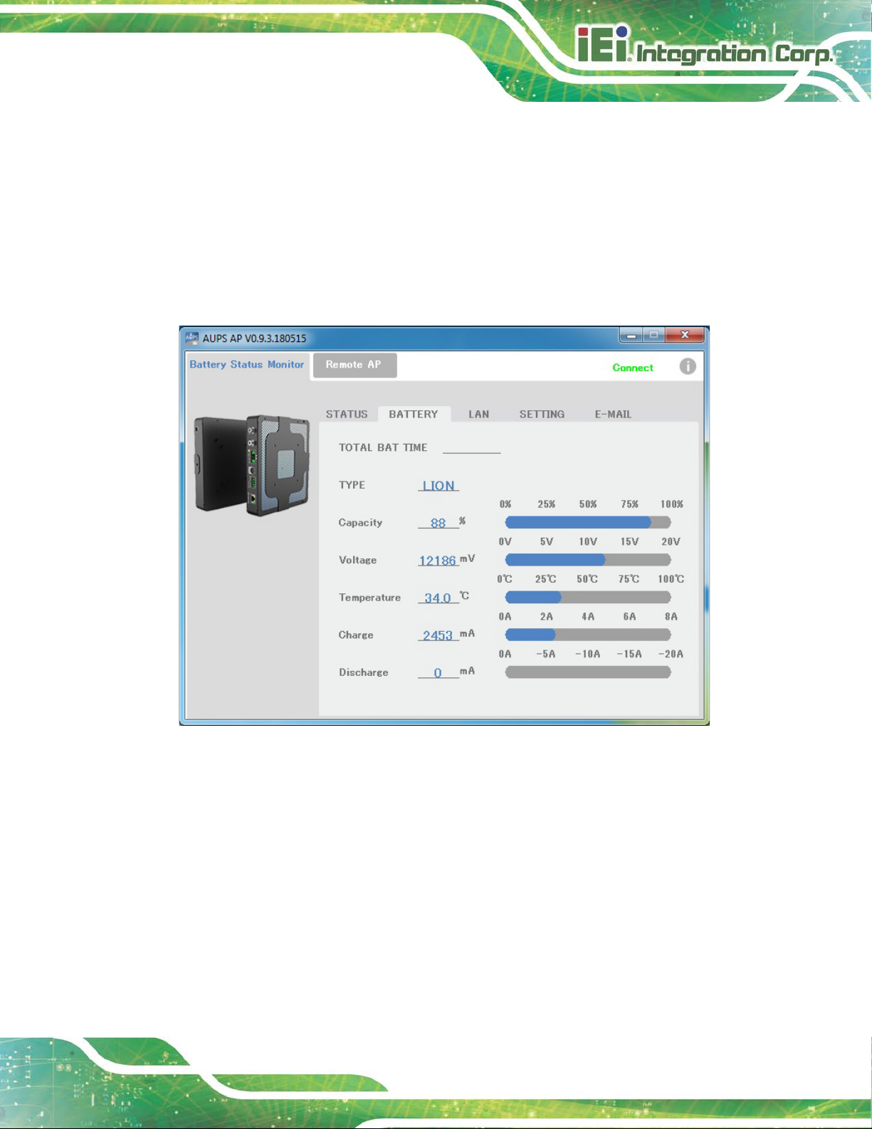
4.4.2 Battery Information
Click on the BATTERY tab to view the information of battery. The total battery time is
shown in the top of the battery screen to indicate the total battery remaining time (this
information will not be displayed when the battery is being charged).
Other information includes battery type, capacity, output voltage, temperature, charging
rate and discharging rate (Figure 4-14). The values li st ed are updated per second.
Figure 4-14: Battery Information
Page 44

AUPS Series Power Module User Manual
Page 34
4.4.3 LAN Setting
The LAN page is where to configure the Remote LAN settings for power on/off remote
control and battery monitoring. To save the modified Host Name, click the SET
button.
Figure 4-15: LAN Setting
Page 45

AUPS Series Power Module User Manual
Page 35
4.4.3.1 Using Static IP
DHCP is enabled by default in the application. To use static IP, disable the DHCP option
and fill in the network information. To s ave the modified parameters of this page, click the
SET button. To load the default settings, click button.
Figure 4-16: LAN Setting – Disable DHCP
Page 46

AUPS Series Power Module User Manual
Page 36
4.4.4 Setting
Click on the SETTING tab to configure the following settings (Figure 4-17).
Figure 4-17: Application Setting
Buzzer Enable or disable the buzzer that warns when the system is
switching to use battery power.
Enable LAN Enable or disable the LAN for remote monitoring function.
Power Click the button to power off the AUPS power module
immediately.
Auto DC on Enable to automatically power on the AUPS once DC power is
applied.
Shut down condition
(capacity %)
DC off delay time
(0~65536 sec)
Set the battery capacity parameter for the system to shut
down automatically.
Set the delay time for the AUPS series to power off after the
system shut down.
Page 47

AUPS Series Power Module User Manual
Page 37
System will be
down-converted
(capacity %)
System go to sleep mode
(capacity %)
4.4.5 E-mail
The E-MAIL page is where to set the SMTP settings for sending alert notification via
e-mail. This page contains three alert options for you to choose. They are:
NOTE: To save the SMTP settings, fully exit the AUPS application by right-clicking (or
Set the battery capacity parameter for the system to
automatically switch to th e Balanced power plan set in its
Windows OS.
Set the battery capacity parameter for the system to go into
sleep mode automatically.
DC adapter power off
System go to sleep mode
DC adapter power restored
long-pressing) the AUPS icon on the task bar and select Exit.
Figure 4-18: E-mail Setting
Page 48

AUPS Series Power Module User Manual
Page 38
4.5 Remote Control and Monitoring
The AUPS Series can be controlled (power on/off) and monitored through a remote
computer located in the same subnet with the AUPS Series. To control and monitor the
AUPS Series remotely, follow the steps below.
Step 1: Connect the RJ-45 remote LAN connector on the bottom panel of the AUPS
Series (Figure 4-19) to a local area network connector.
Figure 4-19: RJ-45 Remote LAN Connector
Step 2: In a remote computer, install the IEI AUPS application by following the
instruction described in Section 4.2. After installation, launch the AP.
Step 3: On the IEI AUPS application screen, click the Remote AP tab (Figure 4-20). All
the AUPS Series modules i n the same subnet with this remote computer are
shown in the list on the right. Check to select one or m ul tiple device(s), then two
function buttons will show on the left.
- Power: Click the button to power off the selected AUPS power module(s)
immediately.
- Shut Down: Click the button to make the remote system(s) shut down after 30
seconds.
Page 49

AUPS Series Power Module User Manual
Page 39
Figure 4-20: Remote AP
Step 4: To access the web interface for advanced monitoring and functions, double click
the IP address of the connected AUPS Series.
Figure 4-21: Remote AP – IP Address
Page 50

AUPS Series Power Module User Manual
Page 40
Step 5: The following page shows in a web browser.
Figure 4-22: Remote Management Web Interface - Status
Step 6: To send an email to an administrator through the SMTP server, click Send
E-mail button on the left. Fill out the information as indicated in Figure 4-23.
Click the Send Message button to send the email.
Figure 4-23: Remote Management Web Interface - Send Email
Page 51

AUPS Series Power Module User Manual
Page 41
Step 7: To configure the AUPS Series network setti ng, click the Configuration button
on the left.
Step 8: A window prompts for the user name and password. The default user name and
password for the LAN setting page are:
User name: admin
Password: IEI
Figure 4-24: Enter User Name and Password
Step 9: The Board Configuration window appears. Conf i gure the network settings and
click the Save Config button. Incorrect settings may cause the bo ard to lose
network connectivity. Step 0:
Page 52

AUPS Series Power Module User Manual
Page 42
Figure 4-25: Remote Management Web Interface - Configuration
Page 53

AUPS Series Power Module User Manual
Page 43
Appendix
A
A Safety Precautions
Page 54

AUPS Series Power Module User Manual
Page 44
DANGER!
1. Disassemble and Reconstruction
“Do not disassemble or reconstruct battery”
The battery pack has safety function and prote ct i on circuit to avoid the danger. If they have
serious damage, it will cause the generat i ng heat, smoke, rupture or flame.
2. Short-circuit
“Do not short-circuit battery”
Do not connect the + and – terminals with metal s (such as wire). Do not carry or store the
battery with metal objects (such as wire, necklace or hairpins). If the battery is short-circuited,
excessive large current will flow and then t he generating heat, smoke, rupture of flame will
occur. And also, it causes generating heat at metals.
3. Incineration and Heating
“Do not incinerate or heat the battery”
These occur the melting of insulator, damage of gas release vent or safety function, or ignition
on electrolyte. Above mentioned matters cause the generating heat, smoke, rupture or flame.
4. Use Nearby Heated Place
“Do not use or leave battery nearby the fire, stove or heated place (more than 80
In case that separator made of polymer i s melted by hi gh temperatu re, the interna l short-circuit
occurs in individual cells and then it causes the generating heat, smoke, rupture or flame. In
addition, do not use the battery under the heated pl ace (more than 80℃) for same reason.
5. Immersion
“Do not immerse the battery in water or sea water, or get it wet”
If the protection circuit included in the bat tery is broken, the battery will be charged at extreme
current or voltage and the abnormal chemical reaction occurs in it. And then it causes the
generating heat, smoke, rupture or flame.
6. Charge Nearby Heated Place
“Do not charge battery nearby the fire or under the blazing sun”
If the protection circuit to avoid the danger works under high temperature or it is broken, the
battery will be charged at abnormal current (or voltage) and abnormal chemical reaction will
occur. It caused the generating heat, smoke, rupture or flame.
℃
)”
7. Charger and Charge Condition
“Do use the specified charger and observe chargi ng requirement”
If the battery is charged with unspecif ied condition (under high temperature over the regulated
value, excessive high voltage or current over re gul ated value, or remodeled charger), there
Page 55

AUPS Series Power Module User Manual
Page 45
are cases that it will be overcharged or the abnormal chemical reaction will occur in cells. It
caused the generating heat, smoke, rupture or flame.
8. Penetration
“Do not drive a nail into the battery, strike it by hammer, or tread it”
As the battery might be broken or deformed and then it will be short-circuited, it caused the
generating heat, smoke, rupture or flame.
9. Impact
“Do not give battery impact or throw it”
The impact might cause leakage, heat, smoke, rupture, and/or fire of cell in the battery. And
also if the protection circuit in the battery is broke n, the battery will be charged at abnormal
voltage or current, and abnormal chemical reaction might occur. It might cause leakage, heat,
smoke rupture, and/or fire.
10. Deformation
“Do not use the battery with conspicuous damage or deformation”
It causes the generating heat, smoke, ru pture or flame.
11. Soldering
“Do not make the direct soldering on battery”
As the insulator is melted by heat or the gas release vent (or safety function) is broken, it
caused the generating heat, smoke, rupture or flame.
12. Reverse Charge and Overdischarge
“Do not reverse polarity (and terminals)”
On charging, the battery is reverse-charged and abno rmal chemica l reaction oc curs. And also,
there may be case that unexpected large current f lows on discharging. These cause the
generating heat, smoke, rupture or flame.
13. Reversed Polarity Use
“Do not reverse-charge or reverse-connect”
The battery has polarity. In case the battery is not connected with charger or equipment
smoothly, do not force them to connect and do check polarity of battery. If the battery is
connected to opposite polarity with charger, it will be reverse-charged and abnormal chemical
reaction will occur. It causes the gen erat ing heat, smoke, rupture or flame.
14. Connect Battery to the Plug
“Do not connect battery to the plug socket or ca r-cigarette-plug”
Added high voltage to the battery, the excessive current will flow in it and then it wil l cause the
generating heat, smoke, rupture or flame.
Page 56

AUPS Series Power Module User Manual
Page 46
15. Inappropriate Use for Other Equipment
“Do not use battery for other equipment”
If the battery is used for unspecified equipment, it will deterio rate its perf ormance and cycle-life.
At worst, abnormal current will flow or battery m ay generate heat, smoke, rupture or flame.
16. Leakage
“Do not touch a leaked battery directly”
in case the leaked electrolyte gets into eyes, wash them with fresh water as soon as possible
without rubbing eyes. And then, see a doctor immediately.
If leave damaged eyes undone, it will cause eye-trouble.
WARNING:
1. Mixed Use
“
Do not use Lithium ion battery in mixture”
Do not use Lithium ion battery with the primary bat teries or secondary batteries whose
capacity kind or maker is different, if do that, the battery will be discharged or charged
excessively in use. And i t may cause t he gen erating, smoke, r upture or f laming b ecause of th e
abnormal chemical reaction in cells.
2. Ingestion
“Keep the battery away from babies”
Keep the little battery out of the reach of babies in order to avoid troubles by swallowing. In
case of swallowing the battery, see a doctor immediately.
3. Charging Time
“Do not continue to charge battery over specified time”
If the battery is not finished charging over regulated time, let it stop charging. There is
possibility that the battery might generate, smoke, rupture or flame.
4. Store
“Do not get into a microwave or a high pressure conta i ner”
It causes the generating, smoke, rapture or flam ing because of a sudden heat or damage of
sealing condition of battery.
5. Leakage
“Do not use a leaked battery nearby fire”
If the liquid leaks from the battery (or the battery gives out bad smell), let the battery leave
from flammable objects immediately. Unless do that, the electrolyte leaked from battery will
catch fire and it will cause the smoke, flaming or rupture of it.
Page 57

AUPS Series Power Module User Manual
Page 47
6. Rust, Changing Color and Deformation
“Do not use an abnormal battery”
In case the battery has bad smell or is generated its changing color or deformation or causes
something wrong in using (includes charging an d st orage), let it take out from equipment or
charger and do not use it. If an abnormal battery is used, it will generate, smoke, rupture or
flame.
CAUTION:
1. Use Under Strong Sunshine
Do not use or leave the battery under t he bl azing su n (or heated car by sunshine). The battery
may generate heat, smoke or flame. And also, it might cause the deterioration of battery’s
characteristics or cycle life.
2. Static Electricity
The battery has the protection circuit to avoid the danger. Do not use nearby the place where
generates static electricity (more than 100 V) which gives damage to the protection circuit. If
protection circuit were broken, the battery would generate, smoke, rupture or flame.
3. Charging Temperature Range
Charging temperature rage is regulated 0℃ and 40℃. Do not charge the battery out of
recommended temperature range. Charging out of recommended range might cause the
generating heat or serious damage of battery. And also, it might cause the deterioration of
battery’s characteristics and cy cle l ife.
4. Manual
Please read the manual before using the battery and keep it after reading.
5. Charging Method
Please read the manual of specified charger about charging method.
6. First Time Use
When the battery has rust, bad smell or somet hing a bnormal at first-time-usin g, d o not use t he
equipment and bring the battery to the shop from which it was purchased.
7. Used By Children
In case younger children use the battery, their parents teach how to use batteries according to
the manual with care. And also, when children are using the batteries, pay attention to use it
according to that or not.
Page 58

AUPS Series Power Module User Manual
Page 48
8. Keep Battery Away From Children
Keep the battery out of the reach of younger children. And also, pay attention when the battery
is taken out from the charger or equipment by li ttle children.
9. Leakage
If the skin or cloth is smeared with liquid from the battery, wash with fresh water. It may cause
the skin inflammation.
Page 59

AUPS Series Power Module User Manual
Page 49
Appendix
B
B Hazardous Materials
Disclosure
Page 60

AUPS Series Power Module User Manual
Page 50
The details provided in this appendix are to ensure that the product is compliant with the
Peoples Republic of China (China) RoHS standards. The table below acknowledges the
presences of small quantities of certain material s in the product, and is applicable t o China
RoHS only.
A label will be placed on each product to indicate the estimated “Environmentally Friendly
Use Period” (EFUP). This is an estimate of the number of years that these substances
would “not leak out or undergo abrupt change.” This product may contain replaceable
sub-assemblies/components which have a shorter EFUP such as batteries and lamps.
These components will be separately marked.
Please refer to the following table.
Part Name Toxic or Hazardous Substances and Elements
Lead
(Pb)
Housing
Display
Printed Circuit
Board
Metal Fasteners
Cable Assembly
Fan Assembly
Power Supply
Assemblies
Battery
O: This toxic or ha zardous substance is contained in all of the homogeneous materials for the part is below the limit
requirement in SJ/T11363-2006 (now replaced by GB/T 26572-2011).
X: This toxic or hazardous substance is contained in at least one of the homogen eous materials for this part is above
O O O O O O
O O O O O O
O O O O O O
O O O O O O
O O O O O O
O O O O O O
O O O O O O
O O O O O O
Mercury
(Hg)
Cadmium
(Cd)
Hexavalent
Chromium
(CR(VI))
Polybrominated
Biphenyls
(PBB)
Polybrominated
Diphenyl Ethers
(PBDE)
the limit requirement in SJ/T11363-2006 (now replaced by GB/T 26572-2011).
Page 61

AUPS Series Power Module User Manual
Page 51
部件名称
有毒有害物质或元素
铅
汞
镉
六价铬
多溴联苯
多溴二苯
醚
壳体
显示
印刷电路板
金属螺帽
电缆组装
风扇组装
电力供应组装
电池
此附件旨在确保本产品符合中国 RoHS 标准。以下表格标示此产品中某有毒物质的含量符
合中国 RoHS 标准规定的限量要求。
本产品上会附有”环境友好使用期限”的标签,此期限是估算这些物质”不会有泄漏或突变”的
年限。本产品可能包含有较短的环境友好使用期限的可替换元件,像是电池或灯管,这些元
件将会单独标示出来。
(Pb)
O: 表示该有毒有害物质在该部件所有物质材料中的含量均在 SJ/T 11363-2006 (现由 GB/T 26572-2011 取代)
标准规定的限量要求以下。
O O O O O O
O O O O O O
O O O O O O
O O O O O O
O O O O O O
O O O O O O
O O O O O O
O O O O O O
(Hg)
(Cd)
(CR(VI))
(PBB)
(PBDE)
X: 表示该有毒有害物质至少在该部件的某一均质材料中的含量超出 SJ/T 11363-2006 (现由 GB/T
26572-2011 取代) 标准规定的限量要求。
 Loading...