

AFL3-W10A/12A/W15A-AL Panel PC
Page I
AFL3-W10A/12A/W15A-AL
MODEL:
Flat Bezel Panel PC with Intel® Celeron® J3455 Quad-Core CPU,
Rev. 1.00 - July 22, 2019
Touchscreen, Dual USB 3.1 Gen 1, Dual GbE LAN, Serial Ports,
HDMI, HD Audio, Wi-Fi, Bluetooth, Optional PoE and RoHS
User Manual
User Manual

AFL3-W10A/12A/W15A-AL Panel PC
Page II
Date Version Changes
July 22, 2019 1.00 Initial release
Revision

AFL3-W10A/12A/W15A-AL Panel PC
Page III
Copyright
COPYRIGHT NOTICE
The information in this document is subject to change without prior notice in order to
improve reliability, design and function and does not represent a commitment on the part
of the manufacturer.
In no event will the manufacturer be liable for direct, indirect, special, incidental, or
consequential damages arising out of the use or inability to use the product or
documentation, even if advised of the possibility of such damages.
This document contains proprietary information protected by copyright. All rights are
reserved. No part of this manual may be reproduced by any mechanical, electronic, or
other means in any form without prior written permission of the manufacturer.
TRADEMARKS
All registered trademarks and product names mentioned herein are used for identification
purposes only and may be trademarks and/or registered trademarks of their respective
owners.

AFL3-W10A/12A/W15A-AL Panel PC
Page IV
Manual Conventions
WARNING
Warnings appear where overlooked details may cause damage to the
equipment or result in personal injury. Warnings should be taken
seriously.
CAUTION
Cautionary messages should be heeded to help reduce the chance of
losing data or damaging the product.
NOTE
These messages inform the reader of essential but non-critical
information. These messages should be read carefully as any directions
or instructions contained therein can help avoid making mistakes.
HOT SURFACE
This symbol indicates a hot surface that should not be touched without
taking care.

AFL3-W10A/12A/W15A-AL Panel PC
Page V
Table of Contents
1 INTRODUCTION .......................................................................................................... 1
1.1 OVERVIEW .................................................................................................................. 2
1.2 MODEL VARIATIONS ................................................................................................... 3
1.3 FEATURES ................................................................................................................... 3
1.4 FRONT PANEL ............................................................................................................. 4
1.5 REAR PANEL ............................................................................................................... 5
1.6 BOTTOM PANEL .......................................................................................................... 6
1.7 SIDE PANEL ................................................................................................................ 6
1.8 SYSTEM SPECIFICATIONS ............................................................................................ 7
1.9 DIMENSIONS ............................................................................................................. 10
1.9.1 AFL3-W10A-AL Dimensions ............................................................................ 10
1.9.2 AFL3-12A-AL Dimensions ................................................................................ 11
1.9.3 AFL3-W15A-AL Dimensions ............................................................................ 12
2 UNPACKING ............................................................................................................... 13
2.1 UNPACKING .............................................................................................................. 14
2.2 PACKING LIST ........................................................................................................... 15
2.3 OPTIONAL ITEMS ...................................................................................................... 16
3 INSTALLATION ......................................................................................................... 19
3.1 ANTI-STAT I C PRECAUTIONS ...................................................................................... 20
3.2 INSTALLATION PRECAUTIONS ................................................................................... 20
3.3 INSTALLATION AND CONFIGURATION STEPS ............................................................. 21
3.4 REMOVING THE BACK COVER .................................................................................. 21
3.4.1 Reinstalling the Back Cover ............................................................................. 23
3.5 M.2 SSD INSTALLATION ........................................................................................... 24
3.6 HDD INSTALLATION ................................................................................................. 26
3.7 POE MODULE INSTALLATION (OPTIONAL) ............................................................... 28
3.8 RFID READER KIT INSTALLATION (OPTIONAL) ........................................................ 30
3.9 AT/AT X MODE SELECTION ...................................................................................... 33
3.10 COM2 RS-232/422/485 SELECTION ...................................................................... 33

AFL3-W10A/12A/W15A-AL Panel PC
Page VI
3.10.1 COM2 Pinouts ............................................................................................... 33
3.10.2 COM2 Pin 9 Selection ................................................................................... 34
3.11 COM1 CONNECTION .............................................................................................. 35
3.12 FLASH DESCRIPTOR SECURITY OVERRIDE .............................................................. 36
3.13 MOUNTING THE SYSTEM ........................................................................................ 37
3.13.1 Wall Mounting ................................................................................................ 37
3.13.2 Panel Mounting .............................................................................................. 40
3.13.3 Cabinet and Rack Installation ....................................................................... 43
3.13.4 Arm Mounting ................................................................................................ 47
3.13.5 Stand Mounting .............................................................................................. 49
3.13.6 V-Stand Mounting (10.1" and 12.1" Models Only) ........................................ 50
3.14 POWERING ON THE SYSTEM ................................................................................... 52
3.15 CLEAR CMOS ........................................................................................................ 53
3.16 RESET THE SYSTEM ................................................................................................ 54
3.17 SOFTWARE INSTALLATION ...................................................................................... 54
3.17.1 Driver Download ........................................................................................... 55
4 BIOS SETUP ................................................................................................................ 57
4.1 INTRODUCTION ......................................................................................................... 58
4.1.1 Starting Setup ................................................................................................... 58
4.1.2 Using Setup ...................................................................................................... 58
4.1.3 Getting Help ..................................................................................................... 59
4.1.4 Unable to Reboot after Configuration Changes .............................................. 59
4.1.5 BIOS Menu Bar ................................................................................................ 59
4.2 MAIN ........................................................................................................................ 60
4.3 ADVANCED ............................................................................................................... 61
4.3.1 ACPI Settings ................................................................................................... 62
4.3.2 F81866 Super IO Configuration ...................................................................... 63
4.3.2.1 Serial Port n Configuration ....................................................................... 64
4.3.2.1.1 Serial Port 1 Configuration ................................................................ 64
4.3.2.1.2 Serial Port 2 Configuration ................................................................ 65
4.3.3 iWDD H/W Monitor ......................................................................................... 66
4.3.4 USB Configuration ........................................................................................... 67
4.3.5 CPU Configuration .......................................................................................... 68
4.3.6 RTC Wake Settings ........................................................................................... 70

AFL3-W10A/12A/W15A-AL Panel PC
Page VII
4.3.7 Power Saving Configuration ............................................................................ 71
4.3.8 Serial Port Console Redirection ...................................................................... 72
4.3.8.1 Legacy Console Redirection Settings ....................................................... 73
4.3.9 iEi Feature ....................................................................................................... 74
4.4 CHIPSET ................................................................................................................... 75
4.4.1 North Bridge Configuration ............................................................................. 76
4.4.1.1 Internal IGD Configuration ....................................................................... 76
4.4.1.2 LCD Control ............................................................................................. 78
4.4.2 South Bridge Configuration ............................................................................. 79
4.4.2.1 HD-Audio Configuration .......................................................................... 81
4.4.2.2 PCI Express Configuration ....................................................................... 82
4.4.2.2.1 M2_AKEY1 ........................................................................................ 83
4.4.2.3 SATA Configuration .................................................................................. 84
4.5 SECURITY ................................................................................................................. 85
4.6 BOOT ........................................................................................................................ 86
4.7 SAV E & EXIT ............................................................................................................ 88
5 SYSTEM MAINTENANCE ....................................................................................... 90
5.1 SYSTEM MAINTENANCE INTRODUCTION .................................................................. 91
5.2 ANTI-STAT I C PRECAUTIONS ...................................................................................... 91
5.3 TURN OFF THE POWER .............................................................................................. 92
5.4 WLAN CARD REPLACEMENT .................................................................................. 92
5.5 REINSTALLING THE COVER ....................................................................................... 93
6 INTERFACE CONNECTORS ................................................................................... 94
6.1 PERIPHERAL INTERFACE CONNECTORS ..................................................................... 95
6.2 INTERNAL PERIPHERAL CONNECTORS ...................................................................... 96
6.2.1 Battery Connector (BT1) .................................................................................. 97
6.2.2 Debug Port Connector (80PORT1) ................................................................. 97
6.2.3 Digital I/O Connector (DIO1) ......................................................................... 97
6.2.4 Inverter Connector (INV_CN1) ....................................................................... 98
6.2.5 LVDS Connector (LVDS1) ............................................................................... 98
6.2.6 Microphone Connector (DMIC1) .................................................................... 99
6.2.7 M.2 A-Key Slot (M2_AKEY1) .......................................................................... 99
6.2.8 M.2 B-Key Slot (M2_1) .................................................................................. 100

AFL3-W10A/12A/W15A-AL Panel PC
Page VIII
6.2.9 PoE Power Output Connector (POE_VOUT_CN1) ...................................... 101
6.2.10 PoE Power Input Connector (POE_VIN_CN1) ........................................... 102
6.2.11 Power LED Connector (PW_LED1) ............................................................ 102
6.2.12 SATA Connector (SATA1) ............................................................................. 102
6.2.13 Speaker Connector, Left (SPK_L1) .............................................................. 103
6.2.14 Speaker Connector, Right (SPK_R1) ........................................................... 103
6.2.15 SPI Flash Connector (J_SPI1) ..................................................................... 103
6.2.16 SPI Flash Connector, EC (J_SPI2) .............................................................. 104
6.2.17 USB 2.0 Connector (TOUCH_USB1) .......................................................... 104
6.2.18 USB 2.0 Connector (CAM_USB) ................................................................. 104
6.2.19 USB 2.0 Connector (RFID_USB) ................................................................ 105
6.3 EXTERNAL INTERFACE PANEL CONNECTORS .......................................................... 105
6.3.1 Audio Line-out Jack (AUDIO1) ..................................................................... 106
6.3.2 Ethernet Connectors (J1 & LAN2) ................................................................ 106
6.3.3 Power Connector (PWR1) ............................................................................. 106
6.3.4 HDMI Connector (HDMI1) ........................................................................... 107
6.3.5 RS-232 RJ-45 Serial Port (COM1) ................................................................ 107
6.3.6 RS-232/422/485 DB-9 Serial Port (COM2) ................................................... 108
6.3.7 USB 2.0 Connectors (USB20_CN1) .............................................................. 108
6.3.8 USB 3.1 Gen 1 Connectors (USB3-1) ............................................................ 108
6.4 PRECONFIGURED JUMPER SETTINGS ....................................................................... 109
6.4.1 LVDS Panel Voltage Selection Jumper (J_VLVDS1) ..................................... 109
6.4.2 LVDS Panel Resolution Selection Jumper (SW1) .......................................... 109
A REGULATORY COMPLIANCE ............................................................................. 111
B SAFETY PRECAUTIONS ........................................................................................ 11 7
B.1 SAFETY PRECAUTIONS ............................................................................................ 118
B.1.1 General Safety Precautions ............................................................................ 118
B.1.2 Anti-static Precautions ................................................................................... 119
B.1.3 Product Disposal ........................................................................................... 120
B.2 MAINTENANCE AND CLEANING PRECAUTIONS ...................................................... 121
B.2.1 Maintenance and Cleaning ............................................................................ 121
B.2.2 Cleaning Tools ............................................................................................... 121
C BIOS MENU OPTIONS ........................................................................................... 123

AFL3-W10A/12A/W15A-AL Panel PC
Page IX
D WATCHDOG TIMER .............................................................................................. 126
E HAZARDOUS MATERIALS DISCLOSURE ....................................................... 129

AFL3-W10A/12A/W15A-AL Panel PC
Page X
List of Figures
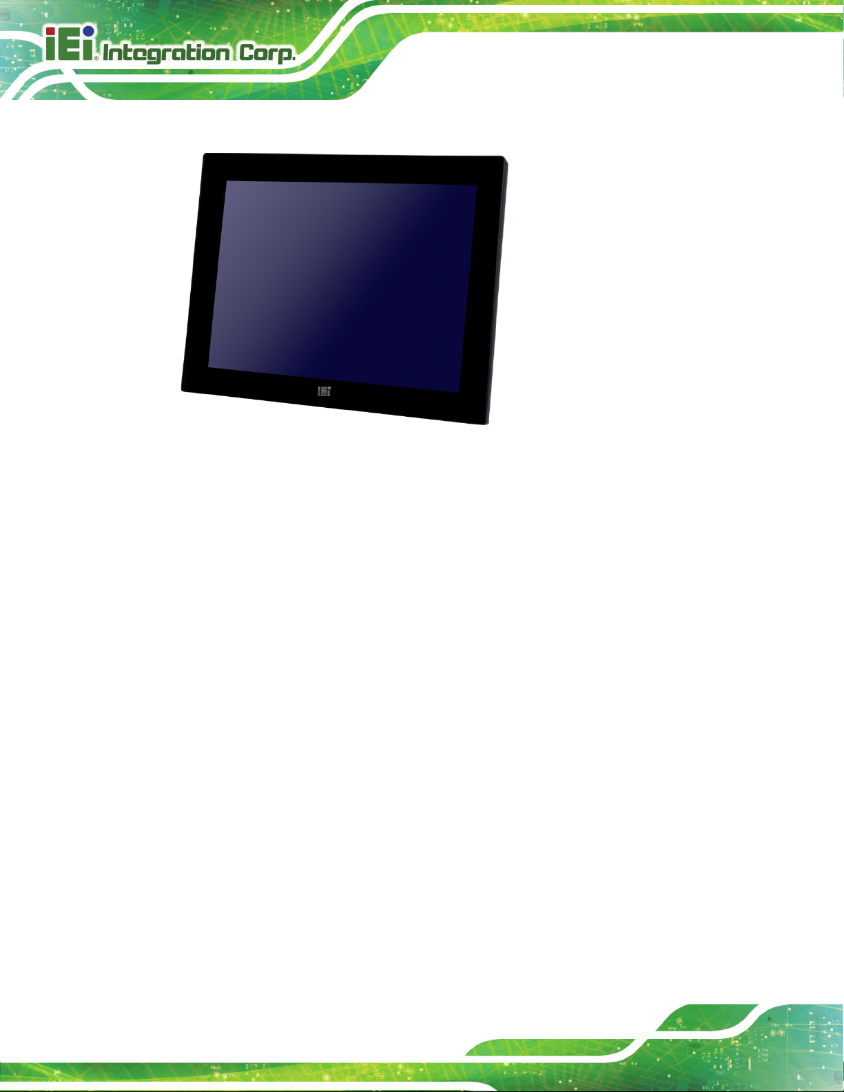
Figure 1-1: AFL3-W10A/12A/W15A-AL Panel PC ......................................................................... 2
Figure 1-2: Front View .................................................................................................................... 4
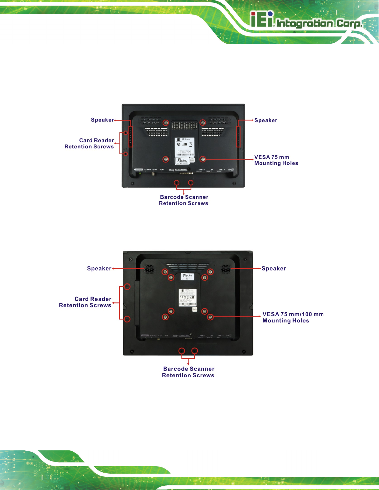
Figure 1-3: AFL3-W10A-AL Rear View .......................................................................................... 5
Figure 1-4: AFL3-12A-AL/AFL3-W15A-AL Rear View .................................................................. 5
Figure 1-5: Bottom Panel ............................................................................................................... 6
Figure 1-6: AFL3-12A-AL / AFL3-W15A-AL Side View ................................................................ 6
Figure 1-7: AFL3-W10A-AL Dimensions (mm) ........................................................................... 10
Figure 1-8: AFL3-12A-AL Dimensions (mm) .............................................................................. 11
Figure 1-9: AFL3-W15A-AL Dimensions (mm) ........................................................................... 12
Figure 3-1: AFL3-W10A-AL Back Cover Retention Screws ...................................................... 21
Figure 3-2: AFL3-12A-AL Back Cover Retention Screws ......................................................... 22
Figure 3-3: AFL3-W15A-AL Back Cover Retention Screws ...................................................... 22
Figure 3-4: Remove the Back Cover ........................................................................................... 23
Figure 3-5: Internal Locking Mechanism .................................................................................... 24
Figure 3-6: M.2 Slot Location ...................................................................................................... 25
Figure 3-7: M.2 SSD Installation .................................................................................................. 25
Figure 3-8: HDD Bracket Retention Screws ............................................................................... 26
Figure 3-9: HDD Retention Screws ............................................................................................. 27
Figure 3-10: HDD Installation ...................................................................................................... 27
Figure 3-11: PoE Module – Cable Connection ........................................................................... 28
Figure 3-12: PoE Module Installation .......................................................................................... 29
Figure 3-13: RFID Reader Kit ....................................................................................................... 30
Figure 3-14: AFL3-W10A-AL RFID Reader Installation ............................................................. 31
Figure 3-15: AFL3-12A-AL RFID Reader Installation ................................................................. 32
Figure 3-16: AFL3-W15A-AL RFID Reader Installation ............................................................. 32
Figure 3-17: AT/ATX Switch Location ......................................................................................... 33
Figure 3-18: DB-9 Serial Port Pin 9 Setting Jumper Location .................................................. 34
Figure 3-19: Serial Device Connector ......................................................................................... 35
Figure 3-20: Flash Descriptor Security Override Jumper Location ........................................ 36
Figure 3-21: Wall-mounting Bracket ........................................................................................... 38
Figure 3-22: Chassis Support Screws ........................................................................................ 39

AFL3-W10A/12A/W15A-AL Panel PC
Page XI
Figure 3-23: Secure the Panel PC ............................................................................................... 40
Figure 3-24: AFL-W10A-AL Cutout Dimensions ........................................................................ 40
Figure 3-25: AFL-12A-AL Cutout Dimensions ........................................................................... 41
Figure 3-26: AFL-W15A-AL Cutout Dimensions ........................................................................ 41
Figure 3-27: Panel Mounting Kit Installation ............................................................................. 42
Figure 3-28: Securing Panel Mounting Brackets ....................................................................... 43
Figure 3-29: Rack/Cabinet Bracket Installation ......................................................................... 44
Figure 3-30: Rack Mounting Kit Installation .............................................................................. 45
Figure 3-31: Securing Rack Mounting Brackets ........................................................................ 46
Figure 3-32: Install into a Rack/Cabinet ..................................................................................... 46
Figure 3-33: Arm Mounting Retention Screw Holes (10.1") ..................................................... 48
Figure 3-34: Arm Mounting Retention Screw Holes (12.1") ..................................................... 48
Figure 3-35: Arm Mounting .......................................................................................................... 49
Figure 3-36: Stand Mounting (Stand-A/Bxx) .............................................................................. 50
Figure 3-37: Drill Pilot Holes for V-Stand ................................................................................... 51
Figure 3-38: Secure V-Stand to System ..................................................................................... 51
Figure 3-39: Secure V-Stand to Mounting Area ......................................................................... 52
Figure 3-40: Powering On the System ........................................................................................ 53
Figure 3-41: Clear CMOS Button Location ................................................................................. 53
Figure 3-42: Reset Button Location ............................................................................................ 54
Figure 3-43: IEI Resource Download Center .............................................................................. 54
Figure 5-1: WLAN Card Location ................................................................................................ 92
Figure 6-1: Main Board Layout Diagram (Front Side) ............................................................... 95
Figure 6-2: Main Board Layout Diagram (Solder Side) ............................................................. 95

AFL3-W10A/12A/W15A-AL Panel PC
Page XII
List of Tables
Table 1-1: Model Variations ........................................................................................................... 3
Table 1-2: System Specifications .................................................................................................. 9
Table 3-1: RS-232/422/485 Serial Port Pinouts .......................................................................... 33
Table 3-2: DB-9 Serial Port Pin 9 Setting Jumper Settings ...................................................... 34
Table 3-3: DB-9 Serial Port (COM1) Pinouts .............................................................................. 36
Table 3-4: Flash Descriptor Security Override Jumper Settings ............................................. 36
Table 6-1: BIOS Navigation Keys ................................................................................................ 59
Table 6-1: Peripheral Interface Connectors ............................................................................... 96
Table 6-2: Battery Connector (BT1) Pinouts .............................................................................. 97
Table 6-3: Debug Port Connector (80PORT1) Pinouts .............................................................. 97
Table 6-4: Digital I/O Connector (DIO1) Pinouts ........................................................................ 97
Table 6-5: Inverter Connector (INV_CN1) Pinouts ..................................................................... 98
Table 6-6: LVDS Connector (LVDS1) Pinouts ............................................................................ 98
Table 6-7: Microphone Connector (DMIC1) Pinouts ................................................................. 99
Table 6-8: M.2 A-Key Slot (M2_AKEY1) Pinouts ......................................................................100
Table 6-9: M.2 B-Key Slot (M2_1) Pinouts ................................................................................101
Table 6-10: PoE Power Output Connector (POE_VOUT_CN1) Pinouts ................................102
Table 6-11: PoE Power Input Connector (POE_VIN_CN1) Pinouts .......................................102
Table 6-12: Power LED Connector (PW_LED1) Pinouts .........................................................102
Table 6-13: SATA Connector (SATA1) Pinouts .......................................................................103
Table 6-14: Left Speaker Connector (SPK_L1) Pinouts ..........................................................103
Table 6-15: Right Speaker Connector (SPK_R1) Pinouts .......................................................103
Table 6-16: SPI Flash Connector (J_SPI1) Pinouts .................................................................103
Table 6-17: EC SPI Flash Connector (J_SPI2) Pinouts ...........................................................104
Table 6-18: USB 2.0 Connector (TOUCH_USB1) Pinouts .......................................................104
Table 6-19: USB 2.0 Connector (CAM_USB) Pinouts ..............................................................104
Table 6-20: USB 2.0 Connector (RFID_USB) Pinouts .............................................................105
Table 6-21: Rear Panel Connectors ..........................................................................................105
Table 6-22: Audio Line-out Jack (AUDIO1) Pinouts ................................................................106
Table 6-23: Ethernet Connectors (J1 & LAN2) Pinouts ..........................................................106
Table 6-24: Ethernet Connector LEDs ......................................................................................106

AFL3-W10A/12A/W15A-AL Panel PC
Page XIII
Table 6-25: Power Connector (PWR1) Pinouts ........................................................................106
Table 6-26: HDMI Connector (HDMI1) Pinouts .........................................................................107
Table 6-27: RS-232 RJ-45 Serial Port (COM1) Pinouts ............................................................107
Table 6-28: RS-232/422/485 DB-9 Serial Port (COM2) Pinouts ...............................................108
Table 6-29: USB 2.0 Connectors (USB20_CN1) Pinouts .........................................................108
Table 6-30: USB 3.1 Gen 1 Connectors (USB3-1) Pinouts......................................................108
Table 6-31: Preconfigured Jumpers .........................................................................................109
Table 6-32: LVDS Voltage Selection Jumper (J_VLVDS1) Settings ......................................109
Table 6-33: LVDS Panel Resolution Selection Jumper (SW1) Settings ................................110

AFL3-W10A/12A/W15A-AL Panel PC
Page XIV
List of BIOS Menus
BIOS Menu 1: Main ....................................................................................................................... 60
BIOS Menu 2: Advanced .............................................................................................................. 61
BIOS Menu 3: ACPI Settings ....................................................................................................... 62
BIOS Menu 4: F81866 Super IO Configuration .......................................................................... 63
BIOS Menu 5: Serial Port n Configuration Menu ....................................................................... 64
BIOS Menu 6: iWDD H/W Monitor ............................................................................................... 66
BIOS Menu 7: USB Configuration ............................................................................................... 67
BIOS Menu 8: CPU Configuration ............................................................................................... 68
BIOS Menu 9: RTC Wake Settings .............................................................................................. 70
BIOS Menu 10: Power Saving Configuration ............................................................................. 71
BIOS Menu 11: Serial Port Console Redirection ....................................................................... 72
BIOS Menu 12: Legacy Console Redirection Settings ............................................................. 73
BIOS Menu 13: iEi Feature ........................................................................................................... 74
BIOS Menu 14: Chipset ................................................................................................................ 75
BIOS Menu 15: North Bridge Configuration .............................................................................. 76
BIOS Menu 16: Internal IGD Configuration ................................................................................ 76
BIOS Menu 17: LCD Control ........................................................................................................ 78
BIOS Menu 18: South Bridge Configuration .............................................................................. 79
BIOS Menu 19: HD-Audio Configuration .................................................................................... 81
BIOS Menu 20: PCI Express Configuration ............................................................................... 82
BIOS Menu 21: M2_AKEY1 ........................................................................................................... 83
BIOS Menu 22: SATA Configuration ........................................................................................... 84
BIOS Menu 23: Security ............................................................................................................... 85
BIOS Menu 24: Boot ..................................................................................................................... 86
BIOS Menu 25: Save & Exit .......................................................................................................... 88

AFL3-W10A/12A/W15A-AL Panel PC
Page 1
Chapter
1
1 Introduction
AFL3-W10A/12A/W15A-AL Panel PC
Page 2
1.1 Overview
Figure 1-1: AFL3-W10A/12A/W15A-AL Panel PC
The AFL3-W10A/12A/W15A-AL series is a quad-core Intel® Celeron® processor J3455
powered flat bezel panel PC with a rich variety of functions and peripherals. The flat-bezel
design is ideal for easy and simplified integration into various applications.
The Intel® Celeron® J3455 is a SoC (System-on-Chip) that ensures optimal memory,
graphics, and peripheral I/O support. The system comes with 4.0 GB of DDR3L SO-DIMM
memory ensuring smooth data throughputs with reduced bottlenecks and fast system
access.
Two serial ports, two external USB 3.1 Gen 1 ports and two external USB 2.0 ports ensure
simplified connectivity to a variety of external peripheral devices. Wi-Fi capabilities and
two RJ-45 Ethernet connectors provide the system with smooth connection to an external
LAN. Moreover, one of the Ethernet connectors is capable to support PoE by installing the
optional PoE module.
AFL3-W10A/12A/W15A-AL Panel PC
Page 3
1.2 Model Variations
The model numbers and model variations are listed below.
Model Size 2.5" HDD Bay
AFL3-W10A-AL-J2/P/PC/4G
AFL3-12A-AL-J2/P/PC/4G
AFL3-W15A-AL-J2/P/PC/4G
Table 1-1: Model Variations
1.3 Features
The AFL3-W10A/12A/W15A-AL features are listed below:
Flat-bezel LCD with LED backlight
Intel® Celeron® processor J3455 (2.0 GHz, quad-core)
Preinstalled with 4 GB of DDR3L memory (system max. 8 GB)
Anti-glare/anti-UV projected capacitive type touchscreen
Wi-Fi 802.11a/b/g/n/ac high speed wireless and Bluetooth v4.1
VESA Mount E-Window
10.1" No 75 No
12.1" Yes 75 & 100 Yes
15.6" Yes 75 & 100 Yes
Two PCIe GbE RJ-45 connectors
Two internal speakers
Two USB 2.0 ports and two USB 3.1 Gen 1 ports
One RS-232/422/485 serial port by D-sub 9 connector
One RS-232 serial port by RJ-45 connector
Optional RFID reader
Optional magnetic stripe card reader
9 V–30 V wide range DC power input; optional PoE support
IP 64 compliant front panel

AFL3-W10A/12A/W15A-AL Panel PC
Page 4
1.4 Front Panel
The front side of the AFL3-W10A/12A/W15A-AL is a flat-bezel panel with a TFT LCD
screen surrounded by a PC/ABS plastic frame (Figure 1-2).
Figure 1-2: Front View
There is a power LED indicator located on the front panel. The status descriptions of the
power LED indicator are listed below.
Off: power cord not attached or power supply failure
Solid amber: the system is connected to a power source and is ready to be
turned on.
Solid green: the system is turned on.
AFL3-W10A/12A/W15A-AL Panel PC
Page 5
1.5 Rear Panel
The rear panel provides access to retention screw holes that support VESA mounting.
See Figure 1-3 and Figure 1-4.
Figure 1-3: AFL3-W10A-AL Rear View
Figure 1-4: AFL3-12A-AL/AFL3-W15A-AL Rear View
AFL3-W10A/12A/W15A-AL Panel PC
Page 6
1.6 Bottom Panel
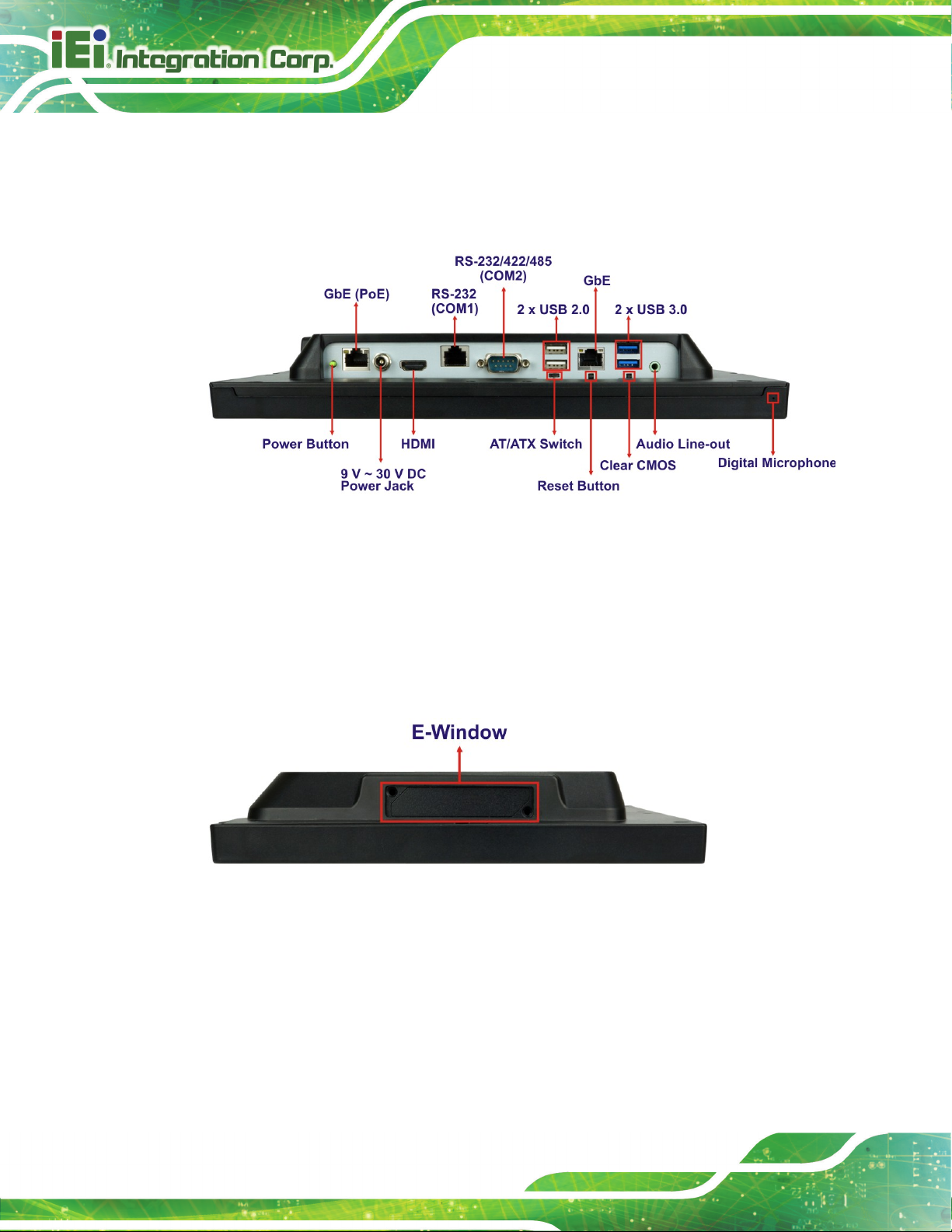
The bottom panel of the AFL3-W10A/12A/W15A-AL has the following connectors and
switches (Figure 1-5).
Figure 1-5: Bottom Panel
1.7 Side Panel
The left side panel of the AFL3-12A-AL / AFL3-W15A-AL has one E-Window that supports
a variety of IEI modules to provide additional connector interface.
Figure 1-6: AFL3-12A-AL / AFL3-W15A-AL Side View
AFL3-W10A/12A/W15A-AL Panel PC
Page 7
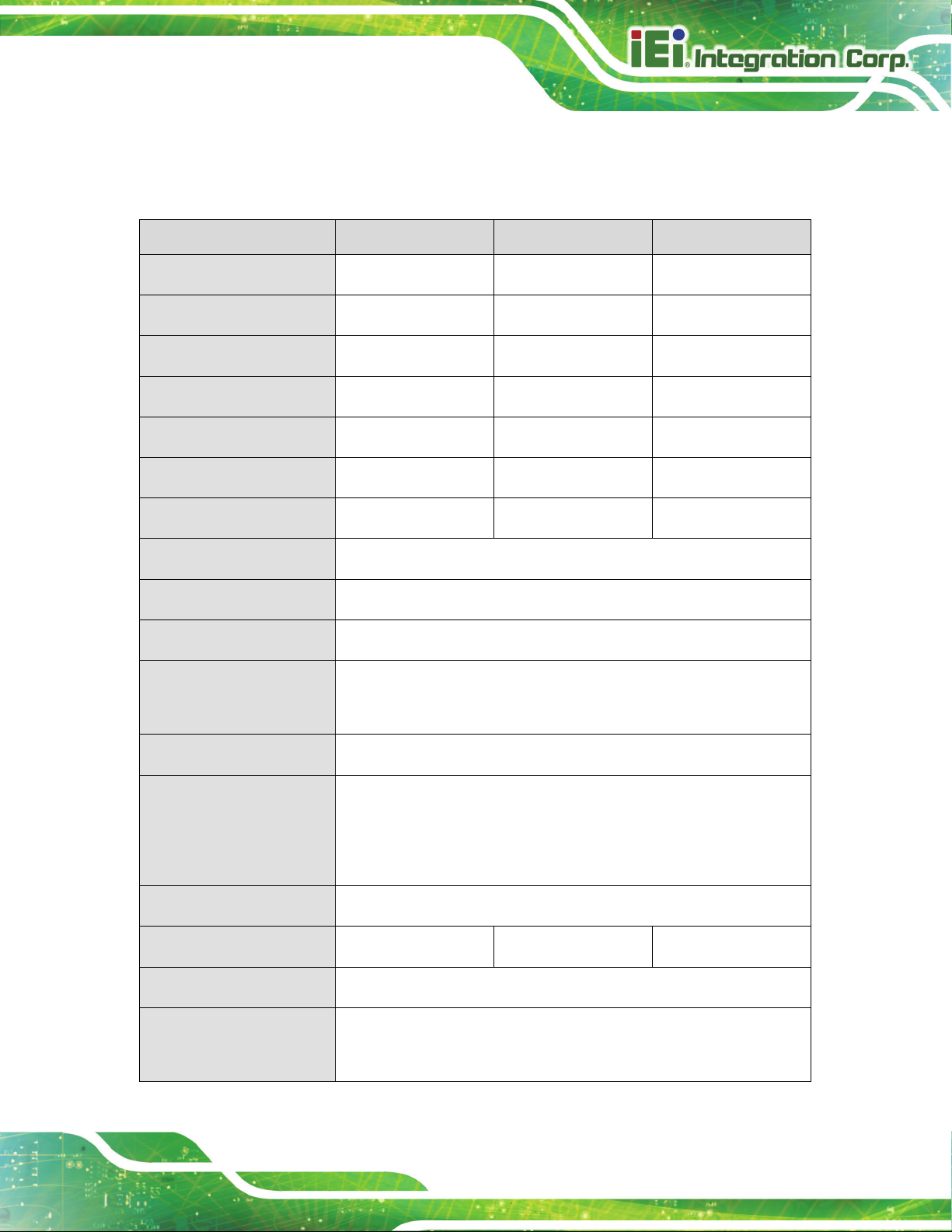
1.8 System Specifications
The technical specifications for the AFL3-W10A/12A/W15A-AL systems are listed below.
Specification AFL3-W10A-AL AFL3-12A-AL AFL3-W15A-AL
LCD Size
Max. Resolution
Brightness (cd/m2)
Contrast Ratio
Viewing Angle (H-V)
Backlight MTBF
Backlight
Touchscreen
Touch Controller
CPU (SoC)
Memory
10.1" 12.1" 15.6" (16:9)
1280 (W) x 800 (H) 1024 (W) x 768 (H) 1366 (W) x 768 (H)
350 500 300
800:1 700:1 500:1
170° / 170° 160° / 160° 170° / 160°
15,000 hrs 50,000 hrs 50,000 hrs
LED LED LED
Anti-glare/Anti-UV projected capacitive
Capacitive type: EETI EXC 3188
Intel® Celeron® processor J3455 (up to 2.3 GHz, quad-core)
One 204-pin 1866 MHz DDR3L SO-DIMM slot preinstalled with
4 GB SDRAM (system max. 8 GB)
Ethernet
Storage
Audio
Internal Speaker
Camera
Wireless
®
Two Intel
One M.2 B+M key 2242 card slot (USB, PCIe and SATA signals) for
SSD installation
One 2.5" SATA 3Gb/s HDD bay
Realtek ALC888 HD Audio codec
Two 2 W Two 3 W Two 3 W
2-megapixel with low light function
One 802.11a/b/g/n/ac wireless LAN module (via M.2 A-key 2230
slot with PCIe/USB signal) supports Bluetooth v4.1
I211 PCIe GbE controllers
AFL3-W10A/12A/W15A-AL Panel PC
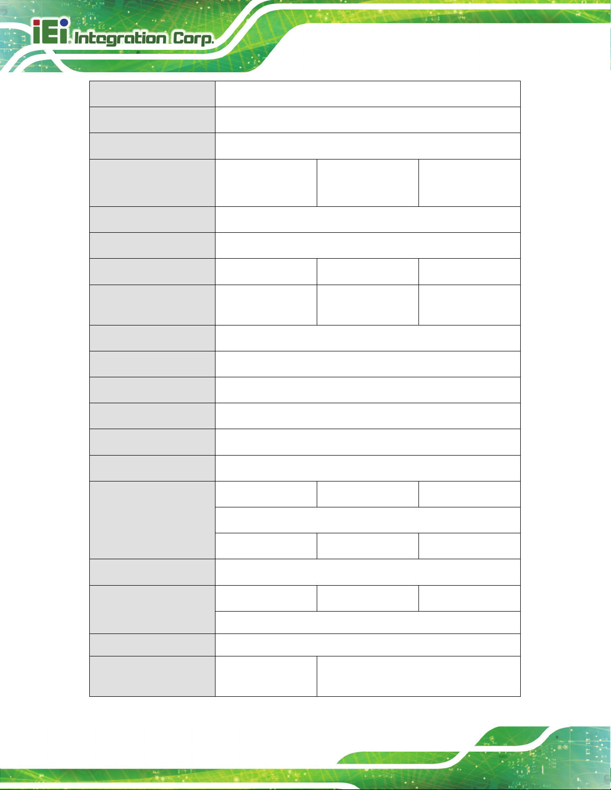
Page 8
RFID Reader
Card Reader
Construction Material
VESA Mount
Mounting
Front Panel Color
Net/Gross Weight
Dimensions (W x H x D)
(mm)
Operating Temperature
Storage Temperature
MIFARE 13.56 MHz card reader (optional)
Magnetic stripe card reader (optional)
PC+ABS plastic
75 mm x 75 mm 75 mm x 75 mm
100 mm x 100 mm
Panel, wall, rack, stand or arm mounting
Black C
1.06 kg / 2.58 kg 1.92 kg / 3.95 kg 3.3 kg / 5.6 kg
261.7 x 180.3 x 42.6 303.4 x 243.4 x 44.4 395.9 x 250.2 x 53.0
-20ºC ~ 50ºC
-20ºC ~ 60ºC
75 mm x 75 mm
100 mm x 100 mm
Humidity
IP Level
Safety/EMC
Erp
Power Supply
Input:
Output:
Power Requirement
Power Consumption
PoE (PD)
E-Window Expansion
10% ~ 95% (non-condensing)
IP 64 compliant front panel
CE, FCC class A
ErP 2009/125/EC
36 W power adapter 60 W power adapter 60 W power adapter
100 V ~ 240 V AC, 50 Hz ~ 60 Hz
12 V DC, 3 A 12 V DC, 5 A 12 V DC, 5 A
9 V ~ 30 V DC
27 W, 12 V @ 2.25 A 43 W, 12 V @ 3.5 A 50 W, 12 V @ 4.16 A
(with Intel® Celeron® J3455 CPU and 4 GB 1866 MHz DDR3L memory)
Optional, single channel
N/A Optional via M.2 B+M key 2242 slot (support
USB/PCIe/SATA signals)

AFL3-W10A/12A/W15A-AL Panel PC
Page 9
I/O Ports and Switches
1 x Audio line-out port
1 x RS-232/422/485 serial port (DB-9 connector)
1 x RS-232 serial port (RJ-45 connector)
2 x GbE LAN (RJ-45 connector)
2 x USB 3.1 Gen 1 (5 Gb/s) connectors
2 x USB 2.0 connectors
1 x HDMI output connector
1 x Power button
1 x AT/ATX switch
1 x Reset button
1 x Clear CMOS button
1 x 9 V ~ 30 V DC input jack
Table 1-2: System Specifications
AFL3-W10A/12A/W15A-AL Panel PC
Page 10
1.9 Dimensions
The following sections list the dimensions of each model.
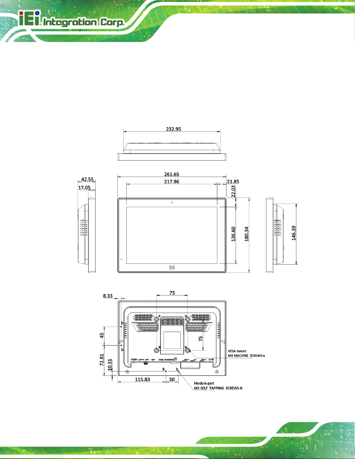
1.9.1 AFL3-W10A-AL Dimensions
The AFL3-W10A-AL dimensions are shown below.
Figure 1-7: AFL3-W10A-AL Dimensions (mm)
AFL3-W10A/12A/W15A-AL Panel PC
Page 11
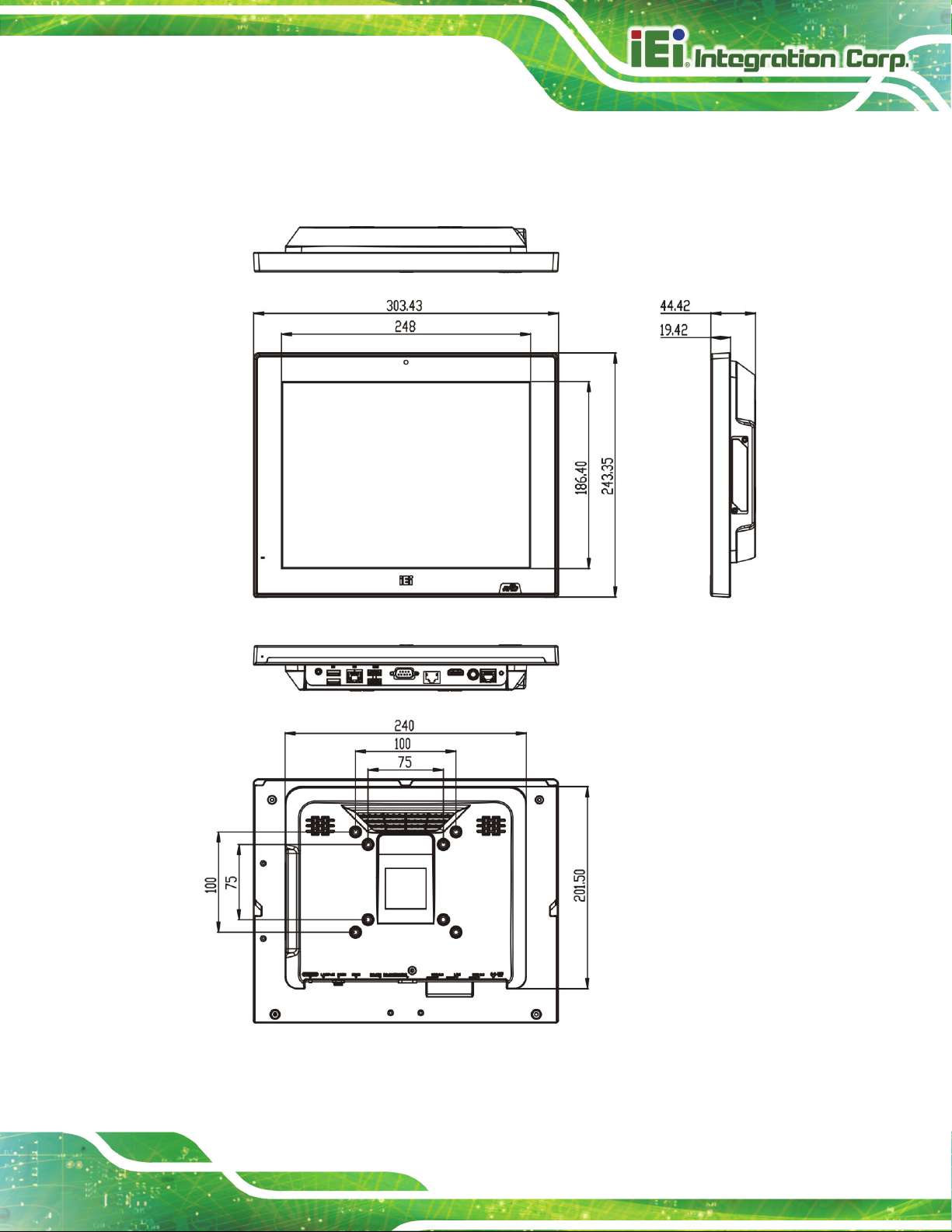
1.9.2 AFL3-12A-AL Dimensions
The AFL3-12A-AL dimensions are shown below.
Figure 1-8: AFL3-12A-AL Dimensions (mm)

AFL3-W10A/12A/W15A-AL Panel PC
Page 12
1.9.3 AFL3-W15A-AL Dimensions
The AFL3-W15A-AL dimensions are shown below.
Figure 1-9: AFL3-W15A-AL Dimensions (mm)

AFL3-W10A/12A/W15A-AL Panel PC
Page 13
Chapter
2
2 Unpacking

AFL3-W10A/12A/W15A-AL Panel PC
Page 14
protective plastic cover stuck to the
installed. This ensures the screen is protected during the installation
2.1 Unpacking
To unpack the panel PC, follow the steps below:
WARNING!
The front side LCD screen has a
screen. Only remove the plastic cover after the panel PC has been properly
process.
Step 1: Use box cutters, a knife or a sharp pair of scissors that seals the top side of the
external (second) box.
Step 2: Open the external (second) box.
Step 3: Use box cutters, a knife or a sharp pair of scissors that seals the top side of the
internal (first) box.
Step 4: Lift the monitor out of the boxes.
Step 5: Remove both polystyrene ends, one from each side.
Step 6: Pull the plastic cover off the panel PC.
Step 7: Make sure all the components listed in the packing list are present. Step 0:

AFL3-W10A/12A/W15A-AL Panel PC
Page 15
If any of the components listed in the checklist below are missing, do not
e installation. Contact the IEI reseller or vendor the
was purchased from or contact an IEI sales
2.2 Packing List
NOTE:
proceed with th
AFL3-W10A/12A/W15A-AL
representative directly.
The AFL3-W10A/12A/W15A-AL panel PC is shipped with the following components:
Quantity Item Image
1 AFL3-W10A/12A/W15A-AL panel PC
1 36 W power adapter for AFL3-W10A-AL
1 60 W power adapter for AFL3-12A-AL and
AFL3-W15A-AL
1 Power cord
1 RJ-45 to DB-9 COM port cable
1 Thermal pad for M.2 SSD module

AFL3-W10A/12A/W15A-AL Panel PC
Page 16
4
Screws (M4*6) for VESA mounting
4
Screws (M3*4) for HDD installation
Backup screws for rear panel installation
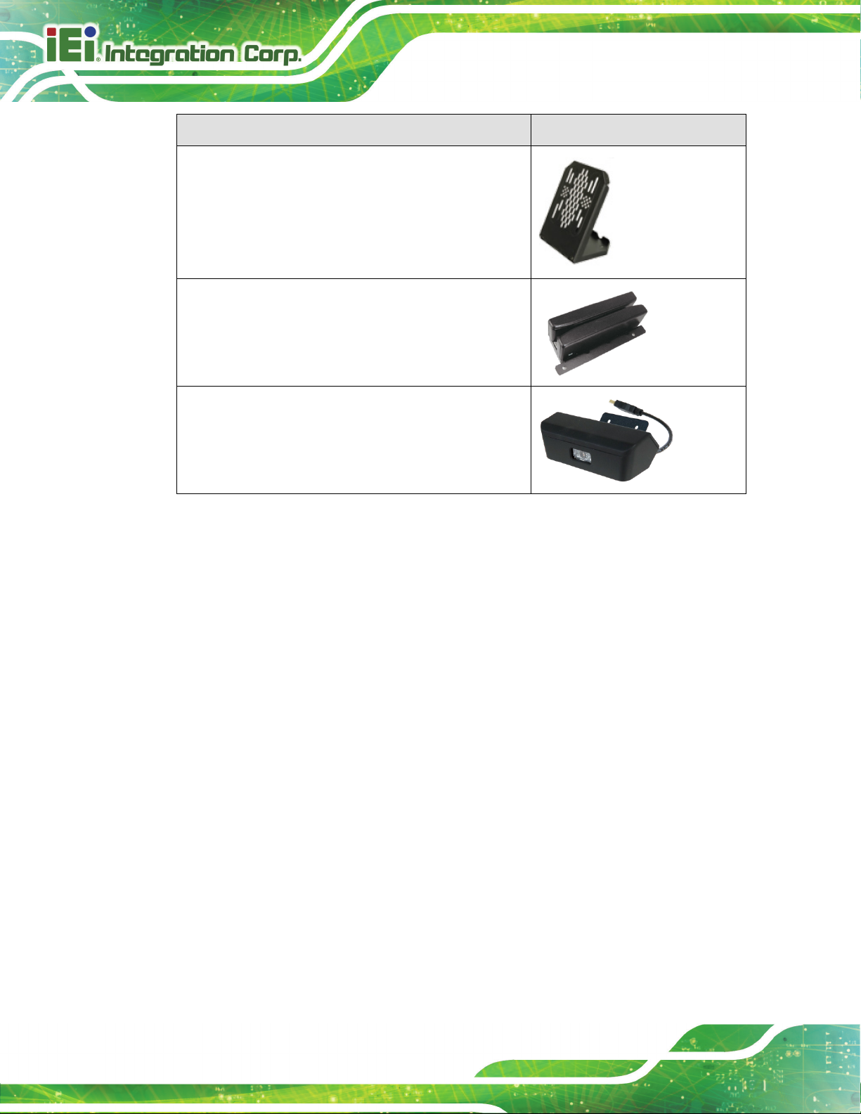
2.3 Optional Items
The following are optional components which may be separately purchased:
Item and Part Number Image
PoE module kit
(P/N: AFL3-PD-BT01-KIT01-R10)
RFID reader kit
VESA 75 wall mount kit
(P/N: AFLWK-12)
VESA 100 wall mount kit
(P/N: AFLWK-19B)

AFL3-W10A/12A/W15A-AL Panel PC
Page 17
Item and Part Number Image
Panel mounting kit for 10.1" and 12.1" SKUs
(P/N: AFL3PK-08A-R10)
Panel mounting kit for 15.6" SKU
(P/N: AFL3PK-W15A-R10)
Rack mounting kit
(10.1": AFL3RK-W10A-R10
12.1": AFL3RK-12A-R10
15.6": AFL3RK-W15A-R11)
Arm
(P/N: ARM-11-RS)
Arm
(P/N: ARM-31-RS)
Stand for VESA 100
(P/N: STAND-A12-RS)
Stand for VESA 75/VESA 100
(P/N: STAND-C12-R10)
AFL3-W10A/12A/W15A-AL Panel PC
Page 18
Item and Part Number Image
LCD monitor stand with adjustable hinge
(10.1": VSTAND-A10
12.1": VSTAND-A12)
Magnetic card reader
(P/N: AFL3P-W10MSR-U-R10)
Barcode scanner
(P/N: AFL3-2D-R11)
If any of these items are missing or damaged, contact the distributor or sales
representative immediately.

AFL3-W10A/12A/W15A-AL Panel PC
Page 19
3 Installation
Chapter
3

AFL3-W10A/12A/W15A-AL Panel PC
Page 20
Failure to take ESD precautions during the maintenance of the
may result in permanent damage to the
3.1 Anti-static Precautions
WARNING:
AFL3-W10A/12A/W15A-AL
AFL3-W10A/12A/W15A-AL and severe injury to the user.
Electrostatic discharge (ESD) can cause serious damage to electronic components,
including the AFL3-W10A/12A/W15A-AL. Dry climates are especially susceptible to ESD.
It is therefore critical that whenever the AFL3-W10A/12A/W15A-AL is accessed internally,
or any other electrical component is handled, the following anti-static precautions are
strictly adhered to.
Wear an anti-static wristband: Wearing a simple anti-static wristband can
help to prevent ESD from damaging the board.
Self-grounding: Before handling the board, touch any grounded conducting
material. During the time the board is handled, frequently touch any
conducting materials that are connected to the ground.
Use an anti-static pad: When configuring the AFL3-W10A/12A/W15A-AL,
place it on an anti-static pad. This reduces the possibility of ESD damaging
the AFL3-W10A/12A/W15A-AL.
Only handle the edges of the PCB: When handling the PCB, hold the PCB
by the edges.
3.2 Installation Precautions
When installing the panel PC, please follow the precautions listed below:
Power turned off: When installing the panel PC, make sure the power is off.
Failing to turn off the power may cause severe injury to the body and/or
damage to the system.
Certified Engineers: Only certified engineers should install and modify
onboard functionalities.
AFL3-W10A/12A/W15A-AL Panel PC
Page 21
Anti-static Discharge: If a user open the rear panel of the panel PC, to
configure the jumpers or plug in added peripheral devices, ground themselves
first and wear an anti-static wristband.
3.3 Installation and Configuration Steps
The following installation steps must be followed.
Step 1: Unpack the panel PC.
Step 2: Install an M.2 SSD or an HDD.
Step 3: (Optional) Install a PoE module.
Step 4: Configure the system.
Step 5: Connect peripheral devices to the panel PC.
Step 6: Mount the panel PC. Step 0:
3.4 Removing the Back Cover
To access the panel PC internally, the back cover must be removed. To remove the back
cover, please follow the steps below.
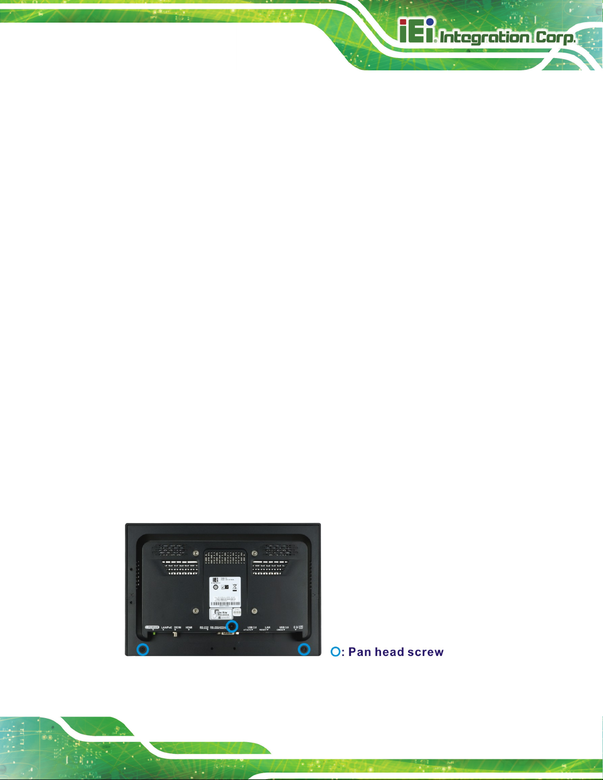
Step 1: Remove the retention screws from the back cover. Two types of screw are used
for securing the back cover of the 12.1" and 15.6" models. See the following
diagrams for detail. Be aware of this for reinstalling the back cover.
Figure 3-1: AFL3-W10A-AL Back Cover Retention Screws
AFL3-W10A/12A/W15A-AL Panel PC
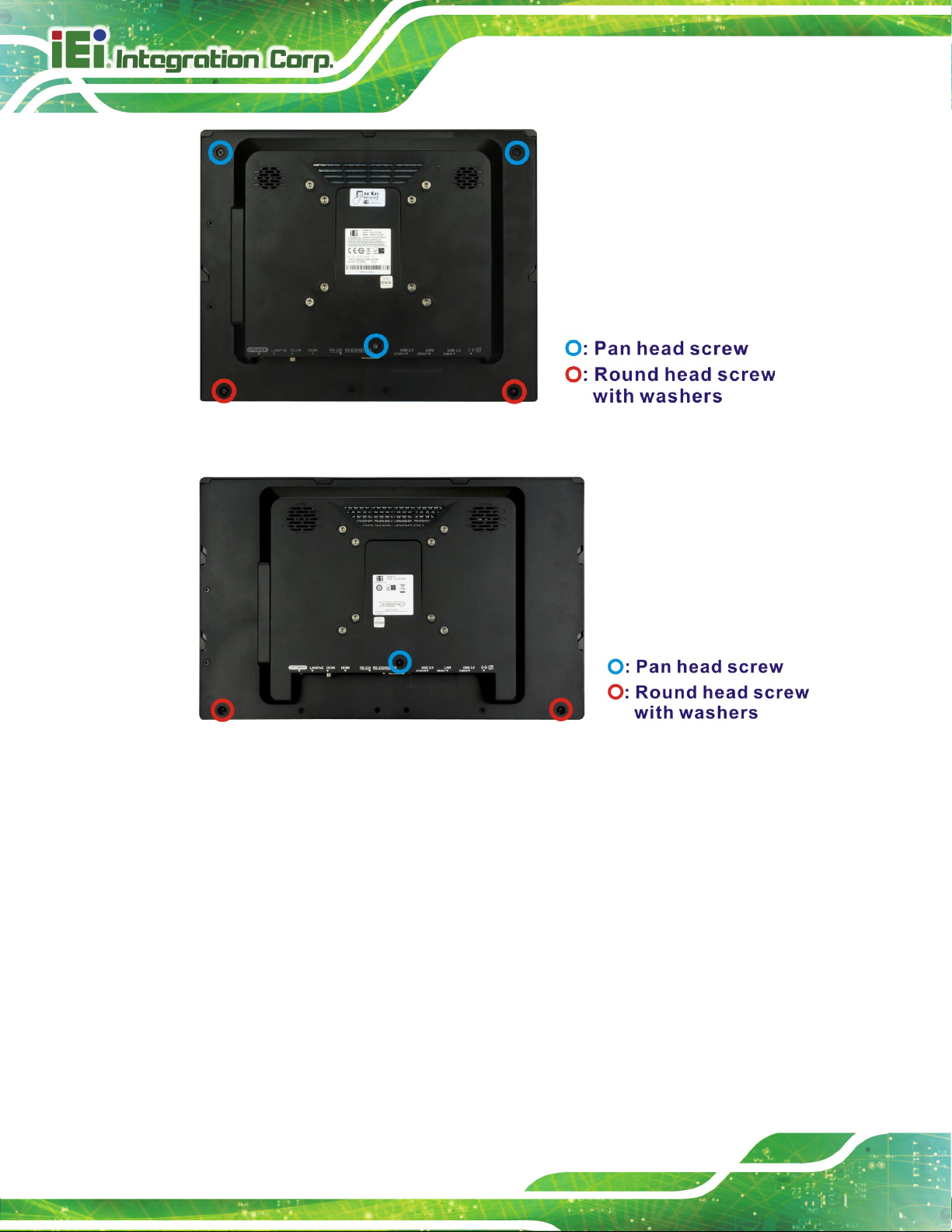
Page 22
Figure 3-2: AFL3-12A-AL Back Cover Retention Screws
o
Figure 3-3: AFL3-W15A-AL Back Cover Retention Screws
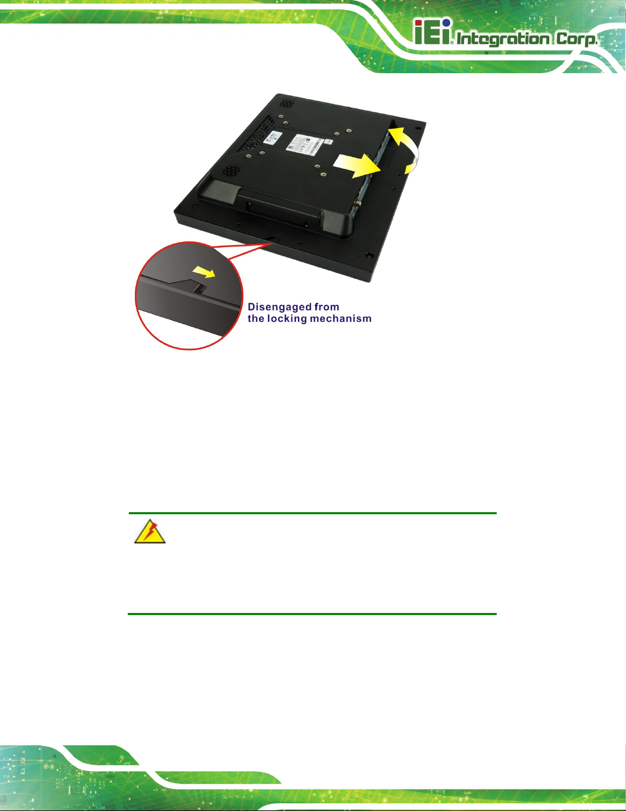
Step 2: Slide the back cover toward the I/O panel until it is disengaged from the locking
mechanism. Then, lift the back cover off the chassis. See Figure 3-4.
AFL3-W10A/12A/W15A-AL Panel PC
Page 23
cover screws will crack the plastic frame.
Figure 3-4: Remove the Back Cover
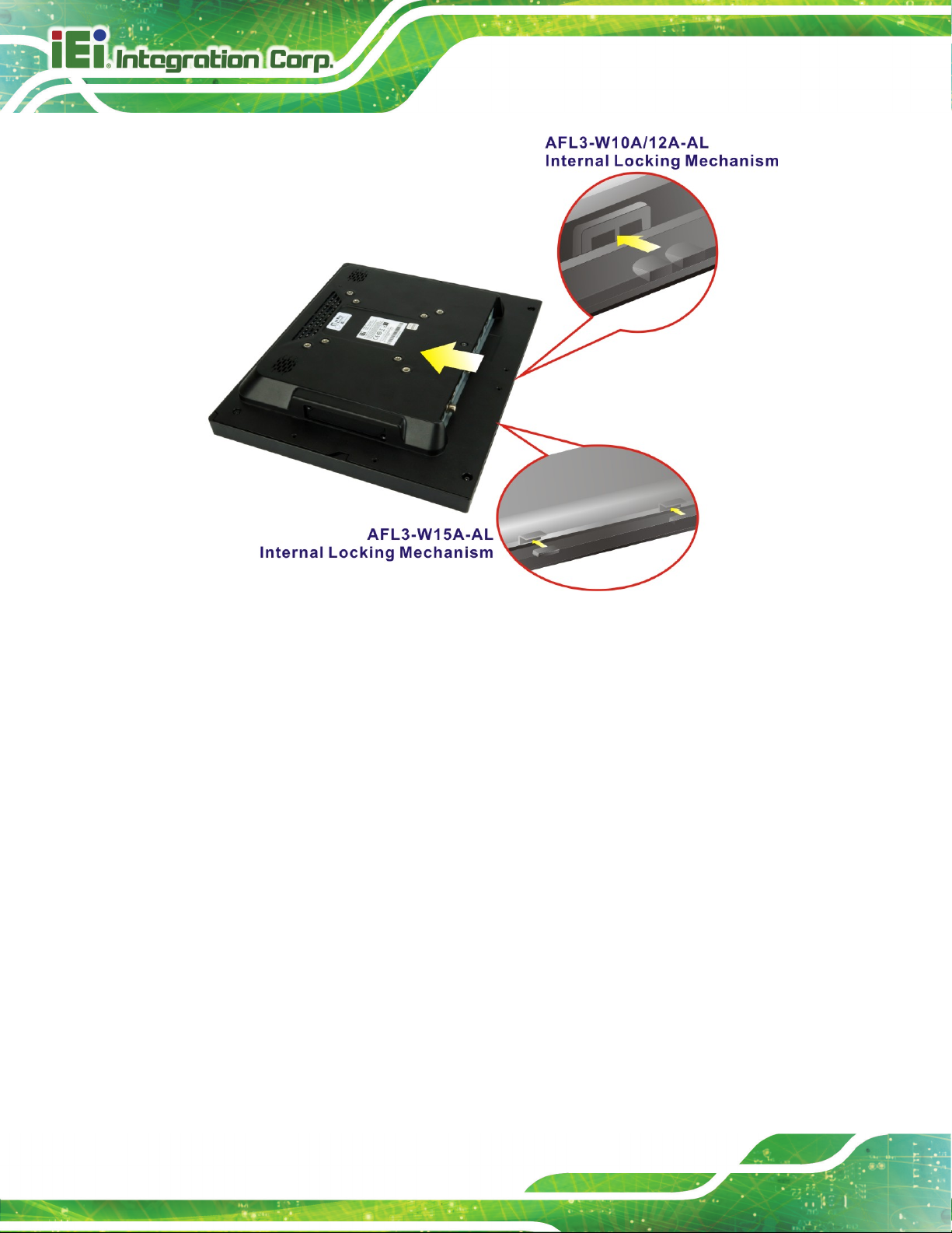
3.4.1 Reinstalling the Back Cover
To install the back cover, slide the back cover toward the top cover until the external and
internal locking mechanisms are both clipped into place. Then, secure the back cover with
the previously removed screws. Please be aware of the type of screws when fastening the
back cover of the 12.1" and 15.6" models (refer to Figure 3-2 and Figure 3-3).
WARNING:
Over-tightening back
Maximum torque for cover screws is 5 kg-cm (0.36 lb-ft/0.49 Nm).
The following diagram shows the differences of the internal locking mechanism of the two
models.
AFL3-W10A/12A/W15A-AL Panel PC
Page 24
Figure 3-5: Internal Locking Mechanism
3.5 M.2 SSD Installation
To install an M.2 SSD into the AFL3-W10A/12A/W15A-AL, please follow the steps below:
Step 1: Remove the plastic back cover. See Section 3.4 above.
Step 2: Locate the M.2 B-key 2242 slot. Remove the preinstalled retention screw on the
screw pillar of the M.2 slot as shown in Figure 3-6.

AFL3-W10A/12A/W15A-AL Panel PC
Page 25
Figure 3-6: M.2 Slot Location
Step 3: Line up the notch on the M.2 SSD with the notch on the connector. Slide the M.2
SSD into the socket at an angle of about 20º (Figure 3-7).
Step 4: Secure the M.2 SSD with the retention screw. Push the other end of the M.2
SSD down and secure the card with the previously removed retention screw
(Figure 3-7).
Figure 3-7: M.2 SSD Installation
Step 5: IMPORTANT! Attach the thermal pad come with the system onto the SSD
module. The sticky side must face down.
Step 6: Reinstall the back cover and secure it using the retention screws. Step 0:
AFL3-W10A/12A/W15A-AL Panel PC
Page 26
3.6 HDD Installation
NOTE:
The HDD drive bay is only available in the 12.1" and 15.6" models. For
the 10.1" model, please install M.2 SSD as the storage device.
To install the HDD into the system, please follow the steps below:
Step 1: Remove the plastic back cover. See Section 3.4 above.
Step 2: Remove the four HDD bracket retention screws as shown below, and lift both
HDD brackets off the panel PC.
Figure 3-8: HDD Bracket Retention Screws
Step 3: Attach the HDD brackets to the HDD. To do this, align the two retention screw
holes in the side of an HDD bracket with the retention screw holes on one side of
the HDD. Insert two retention screws into the HDD bracket to secure it. Follow
the same procedure to secure the other HDD bracket to the HDD (Figure 3-9).

AFL3-W10A/12A/W15A-AL Panel PC
Page 27
Figure 3-9: HDD Retention Screws
Step 4: Connect the SATA cable to the rear of HDD from the motherboard.
Step 5: Install the HDD into the AFL3-W10A/12A/W15A-AL by aligning the retention
screw holes in the HDD brackets with the retention screw holes on the chassis.
Insert the four retention screws.
Figure 3-10: HDD Installation
Step 6: Replace the plastic back cover. Step 0:

AFL3-W10A/12A/W15A-AL Panel PC
Page 28
3.7 PoE Module Installation (Optional)
A PoE module (32 V ~ 57 V input, 12 V output) must be installed and connected before
start using the panel PC as a PoE powered device (PD). To install the optional PoE
module, follow the steps below.
NOTE:
Installing the PoE module in the 12.1" and 15.6" models will occupy the
space for 2.5" HDD installation. Use an M.2 SSD module (B-key 2242)
as the storage device when PoE module installation is required.
Step 1: Remove the plastic back cover. See Section 3.4 above.
Step 2: Connect the two cables came with the PoE module to the corresponding
connectors on the module.
Figure 3-11: PoE Module – Cable Connection

AFL3-W10A/12A/W15A-AL Panel PC
Page 29
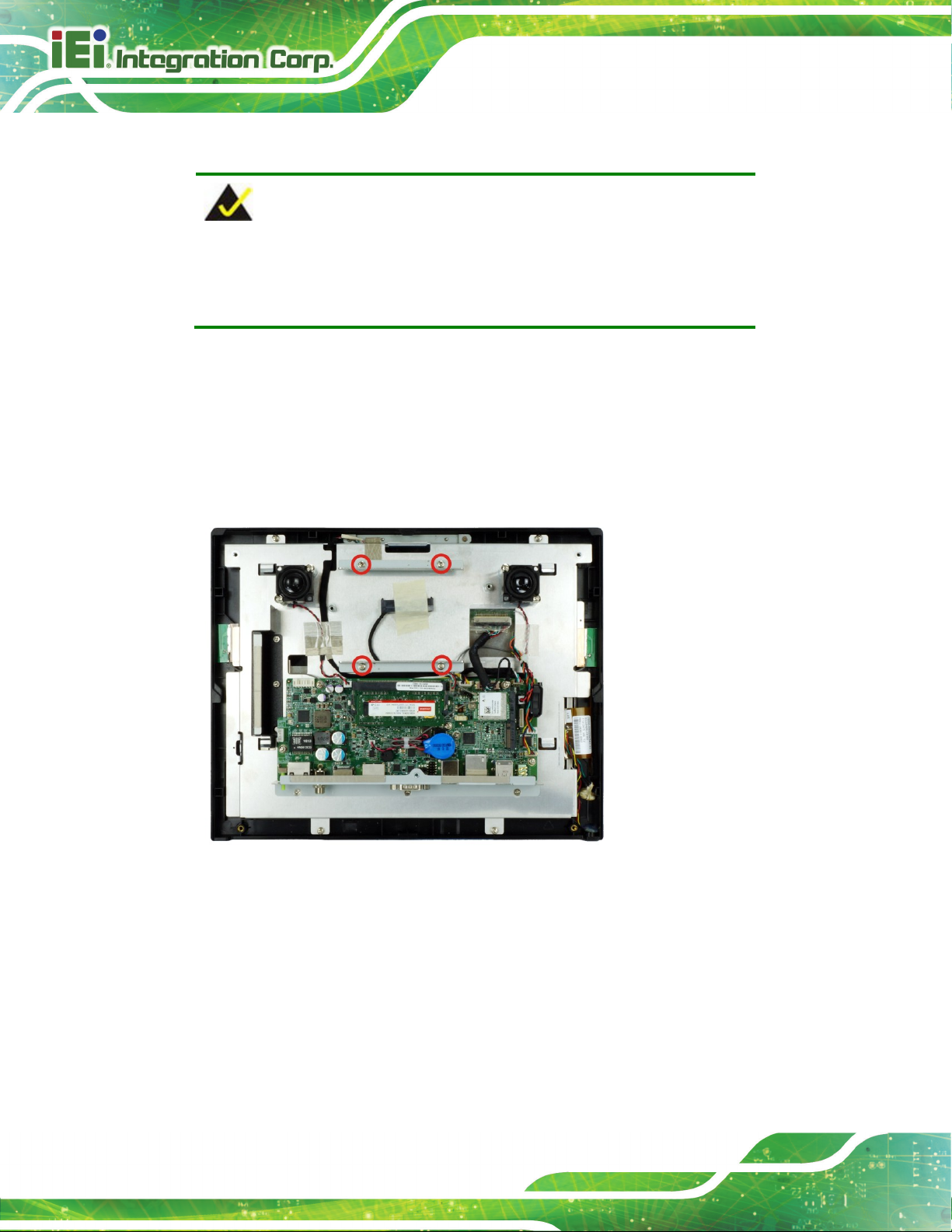
Step 3: The space for installing the PoE module is located inside the chassis, above the
motherboard. Secure the PoE module to the panel PC by using two retention
screws as shown in Figure 3-12.
Step 4: Connect the two cables to the connectors on the motherboard as shown below.
Step 0:
Figure 3-12: PoE Module Installation

AFL3-W10A/12A/W15A-AL Panel PC
Page 30
3.8 RFID Reader Kit Installation (Optional)
The optional RFID reader provided by IEI supports ISO15693, ISO14443A/B, Felica,
Mifare, Tag-it, ST LRI 1K and ST M24LRXX protocols.
To install the RFID reader kit, follow the steps below.
Figure 3-13: RFID Reader Kit
Step 1: Remove the plastic back cover. See Section 3.4 above.
Step 2: Connect the white connector of the RFID cable to the 4-pin connector on the
RFID reader module.
Step 3: Peel off the backing from the RFID reader module and stick the rubber foam on
it.
Step 4: Refer to the following diagrams. Insert the antenna connector into the hole to
make the antenna cable go underneath the metal sheet and come out from
another hole where the RFID reader module will be installed. Tweezers is
needed to pull the antenna cable out of the hole.
Step 5: Connect the antenna cable to the antenna connector (U.FL) on the RFID reader
module.

AFL3-W10A/12A/W15A-AL Panel PC
Page 31
Step 6: Route the cable as shown in the following diagrams and connect the brown
connector of the RFID cable to the RFID connector (RFID_USB) on the system
motherboard.
Step 7: Peel off the backing from the rubber foam and stick it to the system as shown in
the following diagrams.
Step 8: Peel off the backing from the antenna and attach the antenna to the system as
shown in the following diagrams. Step 0:
Figure 3-14: AFL3-W10A-AL RFID Reader Installation

AFL3-W10A/12A/W15A-AL Panel PC
Page 32
Figure 3-15: AFL3-12A-AL RFID Reader Installation
Figure 3-16: AFL3-W15A-AL RFID Reader Installation

AFL3-W10A/12A/W15A-AL Panel PC
Page 33
3.9 AT/ATX Mode Selection
AT or ATX power mode can be used on the AFL3-W10A/12A/W15A-AL. The selection is
made through an AT/ATX switch located on the bottom panel (Figure 3-17).
Figure 3-17: AT/ATX Switch Location
3.10 COM2 RS-232/422/485 Selection
The bottom panel of the AFL3-W10A/12A/W15A-AL has one D-sub 9 male connectors for
RS-232/422/485 connection. The serial communication mode selection can be made
through the BIOS options. Please refer to Section 4.3.2.1.2 for detail information.
3.10.1 COM2 Pinouts
The pinouts of COM2 are detailed below.
Pin RS-232 RS-422 RS-485
1 DCD TXD422- TXD485-
2 RX TXD422+ TXD485+
3 TX RXD422+
4 DTR RXD422-
5 GND
6 DSR
7 RTS
8 CTS
9 RI
Table 3-1: RS-232/422/485 Serial Port Pinouts
AFL3-W10A/12A/W15A-AL Panel PC
Page 34
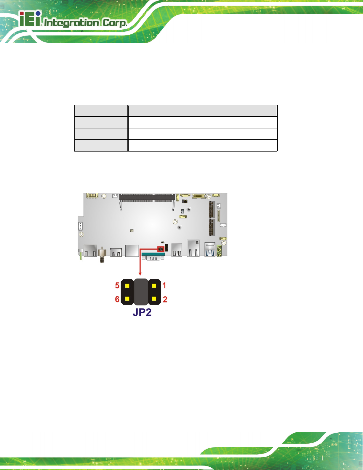
3.10.2 COM2 Pin 9 Selection
The JP2 jumper configures pin 9 on the DB-9 serial port. Pin 9 on the COM2 DB-9
connector can be set as the ring (RI) signal, +5 V or +12 V. The jumper selection options
are shown in Table 3-2.
JP2 Description
Short 1-2 COM2 RI Pin use +5 V
Short 3-4 COM2 RI Pin use RI (Default)
Short 5-6 COM2 RI Pin use +12 V
Table 3-2: DB-9 Serial Port Pin 9 Setting Jumper Settings
The DB-9 Serial Port Pin 9 Setting jumper location is shown in Figure 3-18 below.
Figure 3-18: DB-9 Serial Port Pin 9 Setting Jumper Location
AFL3-W10A/12A/W15A-AL Panel PC
Page 35
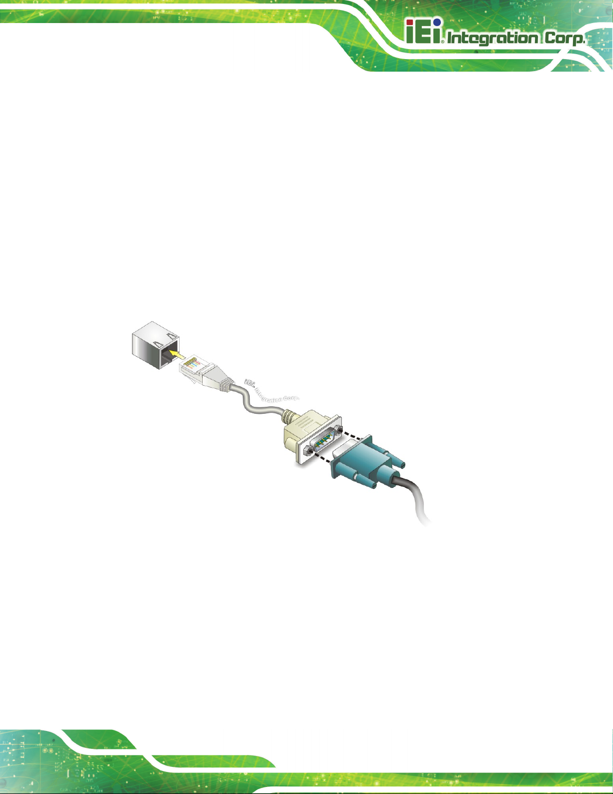
3.11 COM1 Connection
The COM1 port is a RJ-45 serial device connector on the bottom panel. The COM1 port
connects to a cable with a standard D-sub 9 connector at the other end (cables included).
Follow the steps below to connect a serial device to the AFL3-W10A/12A/W15A-AL panel
PC.
Step 1: Locate the RJ-45 connector. The location of the RJ-45 serial port connector is
shown in Chapter 1. The RJ-45 connector for the serial port can be identified
easily as the RJ-45 for the network has two LEDs on the port, while the
connector for the serial cable don’t.
Step 2: Insert the RJ-45 to D-sub 9 cable. See Figure 3-19.
Figure 3-19: Serial Device Connector
Step 3: Insert the serial connector. Insert the D-sub 9 connector of a serial device into
the D-sub 9 connector on the cable.
Step 4: Secure the connector. Secure the serial device connector to the external
interface by tightening the two retention screws on either side of the connector.
The D-sub 9 connector pinouts of the RJ-45 to DB-9 cable are listed below.
AFL3-W10A/12A/W15A-AL Panel PC
Page 36
PIN NO. DESCRIPTION PIN NO. DESCRIPTION
1 NDCD1 6 NDSR1
2 NRX1 7 NRTS1
3 NTX1 8 NCTS1
4 NDTR1 9 NRI1
5 GND
Table 3-3: DB-9 Serial Port (COM1) Pinouts
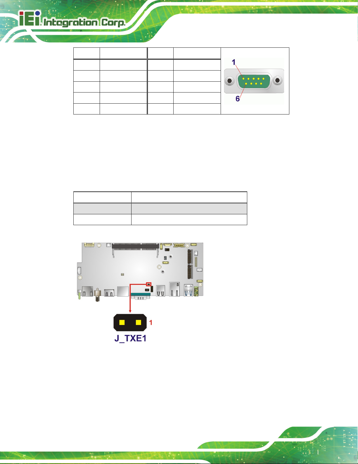
3.12 Flash Descriptor Security Override
The Flash Descriptor Security Override jumper (J_TXE1) allows to enable or disable the
ME firmware update. Refer to Figure 3-20 and Table 3-4 for the jumper location and
settings.
Setting Description
Open Disabled (default)
Short Enabled
Table 3-4: Flash Descriptor Security Override Jumper Settings
Figure 3-20: Flash Descriptor Security Override Jumper Location
To update the ME firmware, please follow the steps below.
Step 1: Before turning on the system power, short the Flash Descriptor Security
Override jumper.

AFL3-W10A/12A/W15A-AL Panel PC
Page 37
Step 2: Update the BIOS and ME firmware, and then turn off the system power.
Step 3: Remove the metal clip on the Flash Descriptor Security Override jumper.
Step 4: Restart the system. The system will reboot 2 ~ 3 times to complete the ME
firmware update.Step 0:
3.13 Mounting the System
The methods of mounting the AFL3-W10A/12A/W15A-AL are listed below.
Wall mounting
Panel mounting
Rack mounting
Arm mounting
Stand mounting
V-Stand mounting
The mounting methods are described below.
3.13.1 Wall Mounting
To mount the panel PC onto the wall, please follow the steps below.
Step 1: Select the location on the wall for the wall-mounting bracket.
Step 2: Carefully mark the locations of the four screw holes in the bracket on the wall.
Step 3: Drill four pilot holes at the marked locations on the wall for the bracket retention
screws.
Step 4: Align the wall-mounting bracket screw holes with the pilot holes.
Step 5: Secure the mounting-bracket to the wall by inserting the retention screws into
the four pilot holes and tightening them (Figure 3-21).
AFL3-W10A/12A/W15A-AL Panel PC
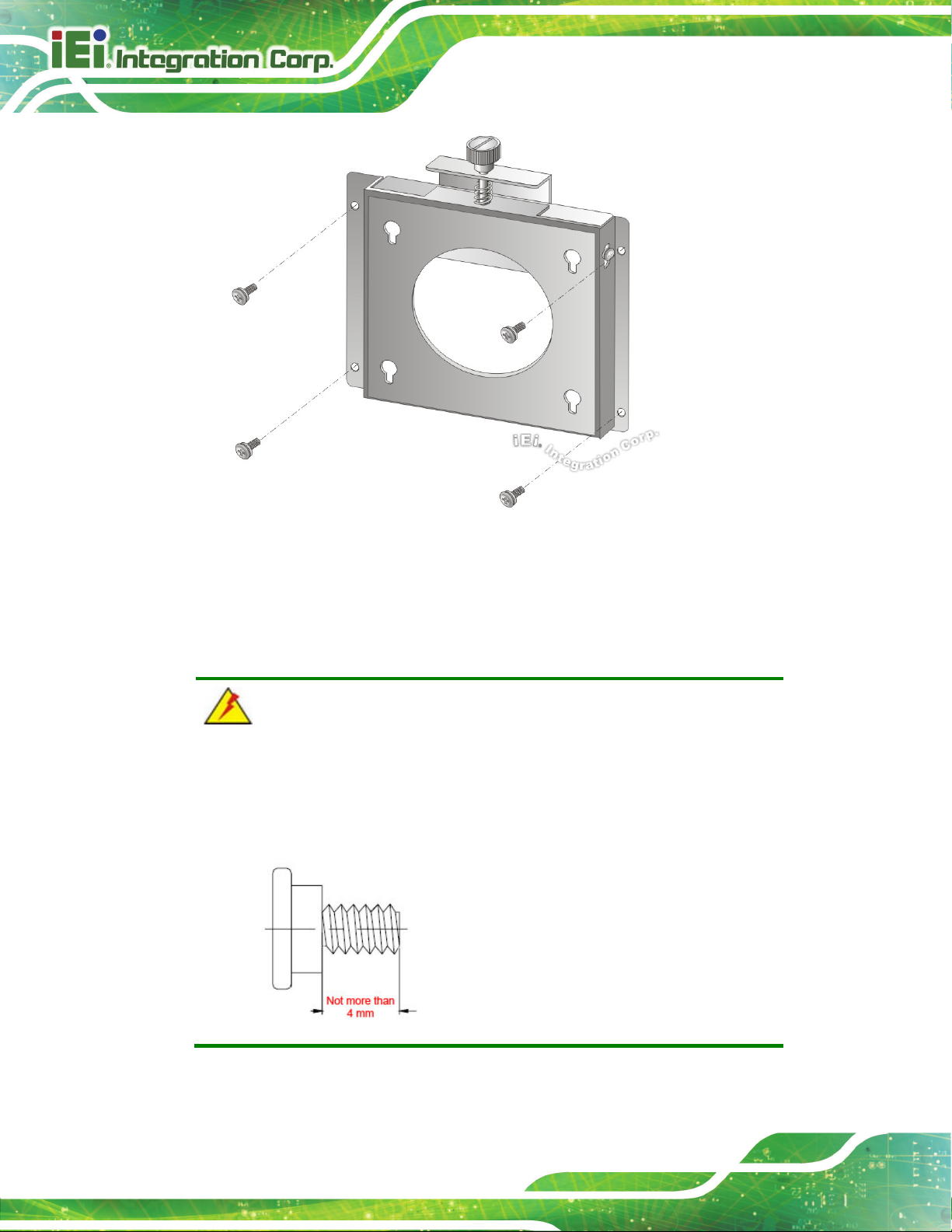
Page 38
Figure 3-21: Wall-mounting Bracket
Step 6: Insert the four monitor mounting screws provided in the wall mount kit into the
four screw holes on the real panel of the panel PC and tighten until the screw
shank is secured against the rear panel (Figure 3-22).
WARNING:
Please use the M4 screws provided in the wall mount kit for the rear panel.
If the screw is missing, the thread depth of the replacement screw should
be not more than 4 mm.
AFL3-W10A/12A/W15A-AL Panel PC
Page 39
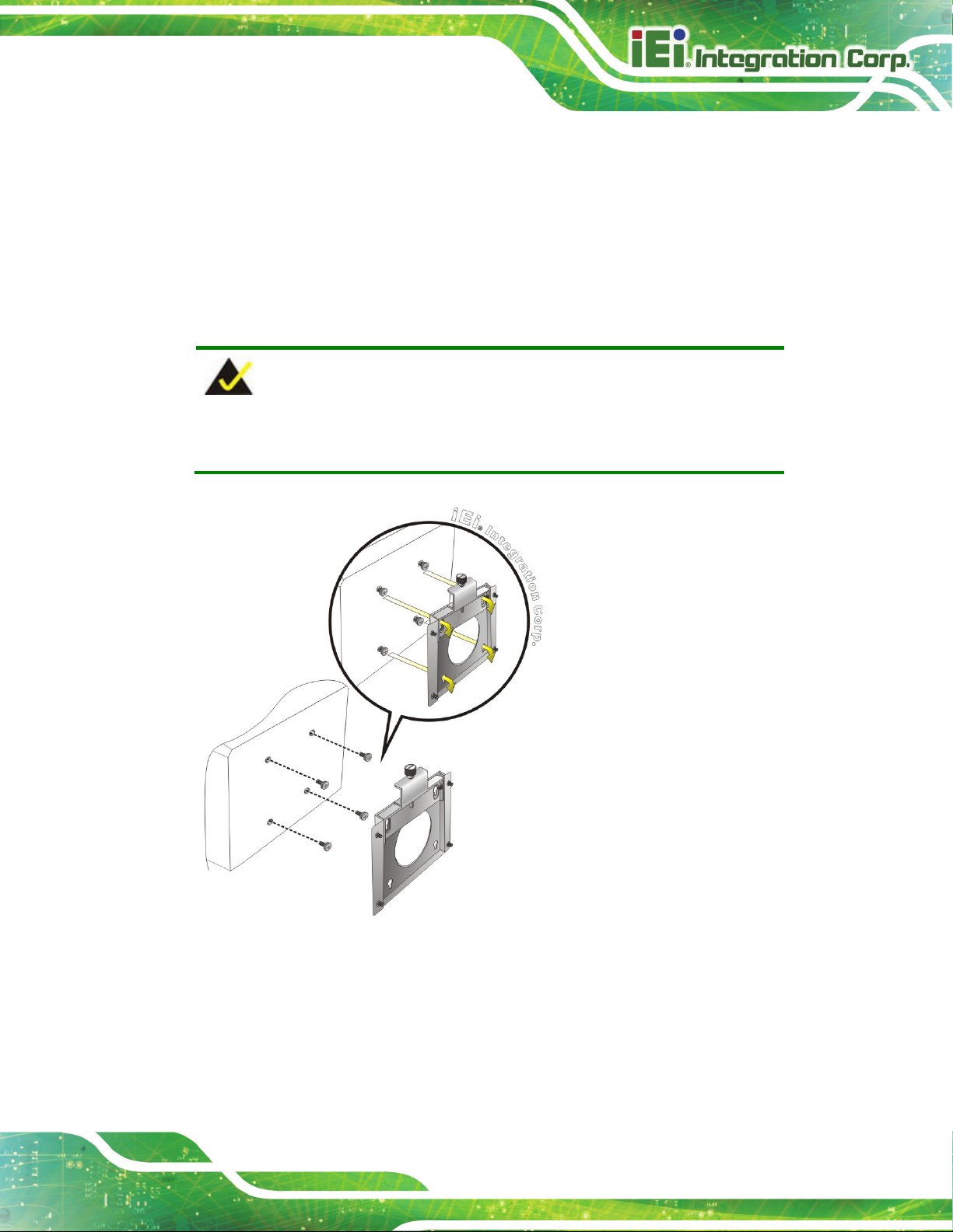
Step 7: Align the mounting screws on the monitor rear panel with the mounting holes on
the bracket.
Step 8: Carefully insert the screws through the holes and gently pull the monitor
downwards until the monitor rests securely in the slotted holes (Figure 3-22).
Ensure that all four of the mounting screws fit snugly into their respective slotted
holes.
NOTE:
In the diagram below the bracket is already installed on the wall.
Figure 3-22: Chassis Support Screws
Step 9: Secure the panel PC by fastening the retention screw of the wall-mounting
bracket (Figure 3-23).
AFL3-W10A/12A/W15A-AL Panel PC
Page 40
Figure 3-23: Secure the Panel PC
3.13.2 Panel Mounting
To mount the AFL3-W10A/12A/W15A-AL panel PC into a panel, please follow the steps
below.
Step 1: Select the position on the panel to mount the panel PC.
Step 2: Cut out a section corresponding to the size shown below. The size must be
smaller then the outer edge.
Figure 3-24: AFL-W10A-AL Cutout Dimensions

AFL3-W10A/12A/W15A-AL Panel PC
Page 41
Figure 3-25: AFL-12A-AL Cutout Dimensions
Figure 3-26: AFL-W15A-AL Cutout Dimensions
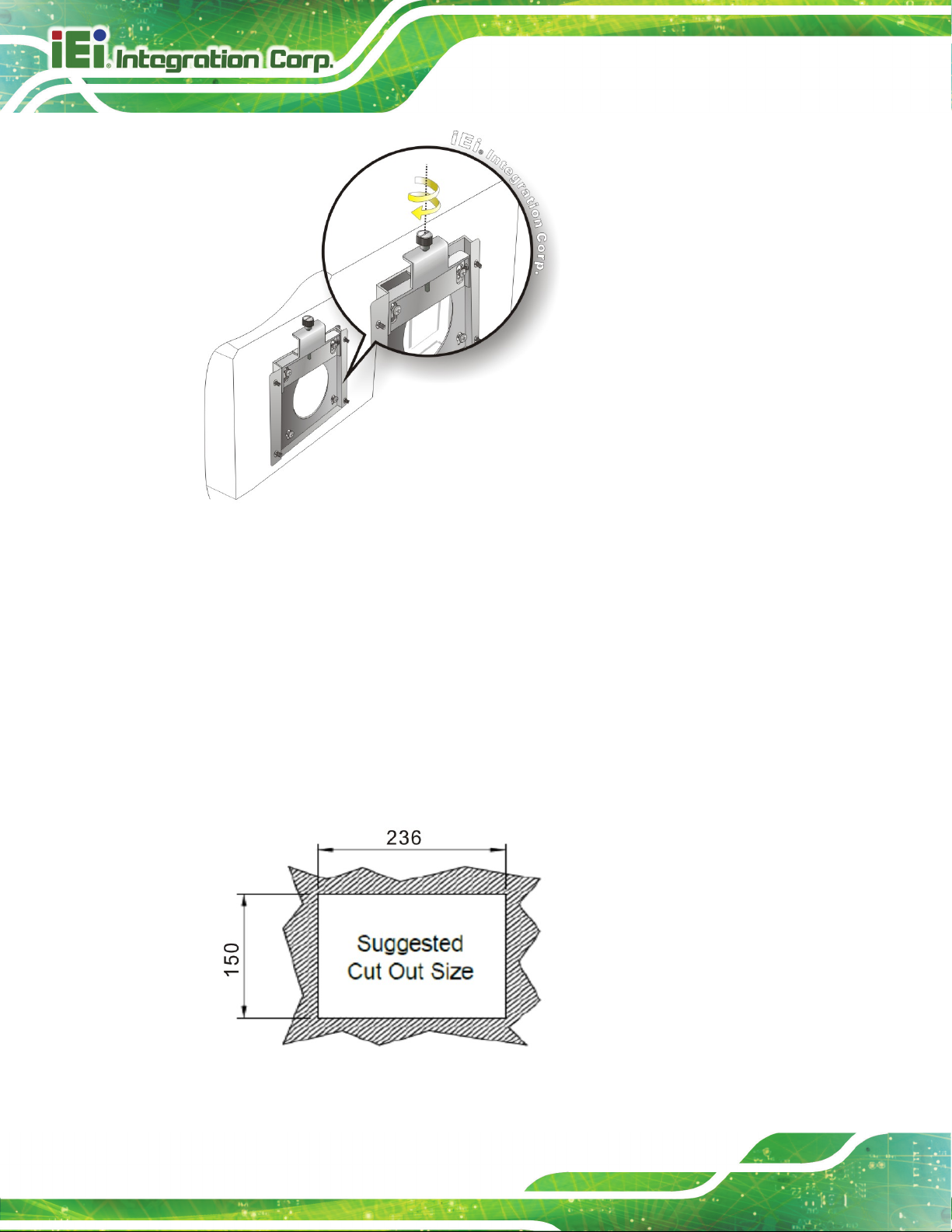
Step 1: Slide the panel PC through the hole until the frame is flush against the panel.
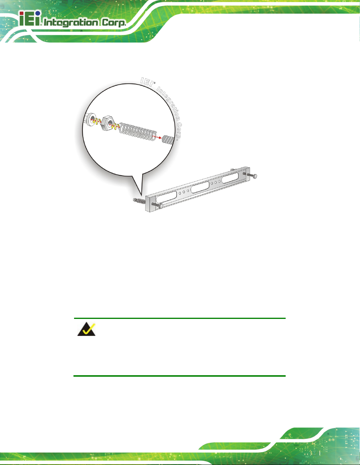
Step 2: Insert a M5*50 screw into the screw hole on the side of the panel mounting
bracket. Then, install the following components onto the screw in sequence.
See Figure 3-27.
Sequence Item Photo Instruction
1 Spring
2 Nut
3 Plastic
cap
Install a spring onto the screw.
Tighten a nut until the spring is
compressed enough for plastic cap.
Tighten a plastic cap onto the end of
screw thread.
AFL3-W10A/12A/W15A-AL Panel PC
Page 42
Step 3: Repeat Step 4 to install the other three screws into the sides of the two panel
mounting brackets.
Figure 3-27: Panel Mounting Kit Installation
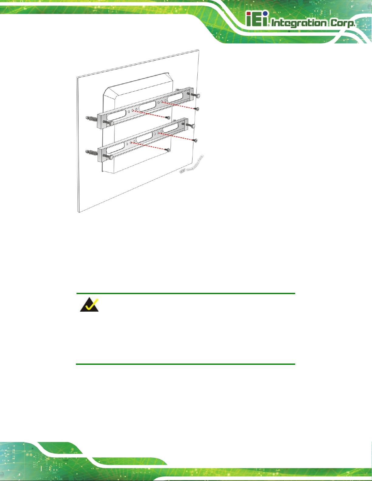
Step 4: Align the panel mounting bracket screw holes with the VESA mounting holes on
the rear of the panel PC.
Step 5: Secure the two panel mounting brackets to the rear of the panel PC by inserting
the four retention screws into the VESA mounting holes and tightening them
(Figure 3-28).St ep 0:
NOTE:
The panel mounting kit described in this section is an optional item. To
purchase it, please contact an IEI sales representative.
AFL3-W10A/12A/W15A-AL Panel PC
Page 43
Figure 3-28: Securing Panel Mounting Brackets
3.13.3 Cabinet and Rack Installation
The AFL3-W10A/12A/W15A-AL panel PC can be installed into a cabinet or rack. The
installation procedures are similar to the panel mounting installation. To do this, please
follow the steps below:
NOTE:
When purchasing the cabinet/rack installation bracket, make sure it is
compatible with both the AFL3-W10A/12A/W15A-AL panel PC and the
rack/cabinet into which the AFL3-W10A/12A/W15A-AL is installed.
Step 1: Slide the rear chassis of the AFL3-W10A/12A/W15A-AL panel PC through the
rack/cabinet bracket until the frame is flush against the front of the bracket
(Figure 3-29).

AFL3-W10A/12A/W15A-AL Panel PC
Page 44
Figure 3-29: Rack/Cabinet Bracket Installation
Step 2: Insert a M5*50 screw into the screw hole on the side of the rack mounting
bracket. Then, install the following components onto the screw in sequence.
See Figure 3-27.
Sequence Item Photo Instruction
1 Spring
2 Nut
3 Plastic
cap
Install a spring onto the screw.
Tighten a nut until the spring is
compressed enough for plastic cap.
Tighten a plastic cap onto the end of
screw thread.
Step 3: Repeat Step 4 to install the other three screws into the sides of the two rack
mounting brackets.

AFL3-W10A/12A/W15A-AL Panel PC
Page 45
Figure 3-30: Rack Mounting Kit Installation
Step 4: Align the rack mounting bracket screw holes with the VESA mounting holes on
the rear of the panel PC.
Step 5: Secure the two rack mounting brackets to the rear of the panel PC by inserting
the four retention screws into the VESA mounting holes and tightening them
(Figure 3-31).
NOTE:
The rack mounting kit described in this section is an optional item. To
purchase it, please contact an IEI sales representative.

AFL3-W10A/12A/W15A-AL Panel PC
Page 46
Figure 3-31: Securing Rack Mounting Brackets
Step 6: Slide the panel PC with the attached rack/cabinet bracket into a rack or cabinet
(Figure 3-32).
Figure 3-32: Install into a Rack/Cabinet

AFL3-W10A/12A/W15A-AL Panel PC
Page 47
VESA compliant it cannot be used to support the
Step 7: Once the panel PC with the attached rack/cabinet bracket has been properly
inserted into the rack or cabinet, secure the front of the rack/cabinet bracket to
the front of the rack or cabinet (Figure 3-32).
3.13.4 Arm Mounting
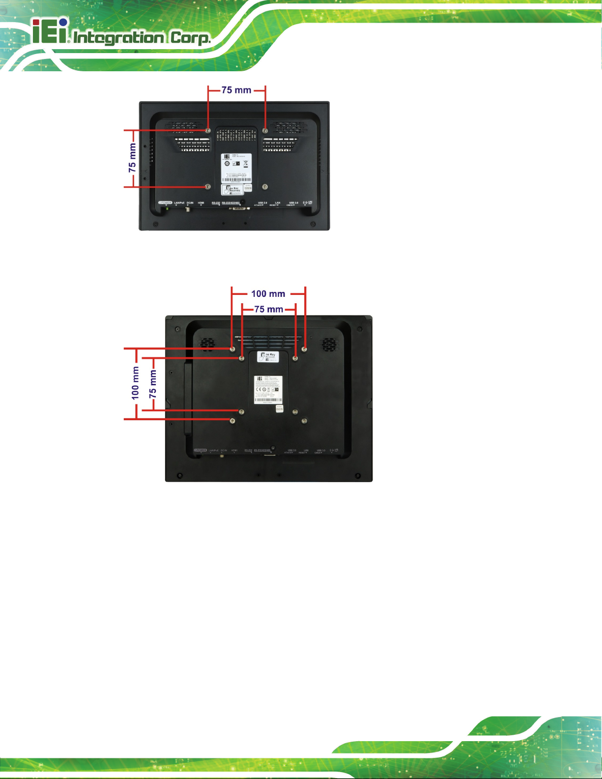
The AFL3-W10A/12A/W15A-AL is VESA (Video Electronics Standards Association)
compliant and can be mounted on an arm with a 75 mm or a 100 mm interface pad. To
mount the AFL3-W10A/12A/W15A-AL on an arm, please follow the steps below.
Step 1: The arm is a separately purchased item. Please correctly mount the arm onto
the surface it uses as a base. To do this, refer to the installation documentation
that came with the mounting arm.
NOTE:
When purchasing the arm please ensure that it is VESA compliant and that
the arm has a 75 mm or a 100 mm interface pad. If the mounting arm is not
AFL3-W10A/12A/W15A-AL panel PC.
Step 2: Once the mounting arm has been firmly attached to the surface, lift the panel PC
onto the interface pad of the mounting arm.
Step 3: Align the retention screw holes on the mounting arm interface with those in the
panel PC (Figure 3-33 and Figure 3-34).
AFL3-W10A/12A/W15A-AL Panel PC
Page 48
Figure 3-33: Arm Mounting Retention Screw Holes (10.1")
Figure 3-34: Arm Mounting Retention Screw Holes (12.1")
Step 4: Secure the AFL3-W10A/12A/W15A-AL to the interface pad by inserting four
retention screws through the mounting arm interface pad and into the
AFL3-W10A/12A/W15A-AL.St ep 0:

AFL3-W10A/12A/W15A-AL Panel PC
Page 49
Figure 3-35: Arm Mounting
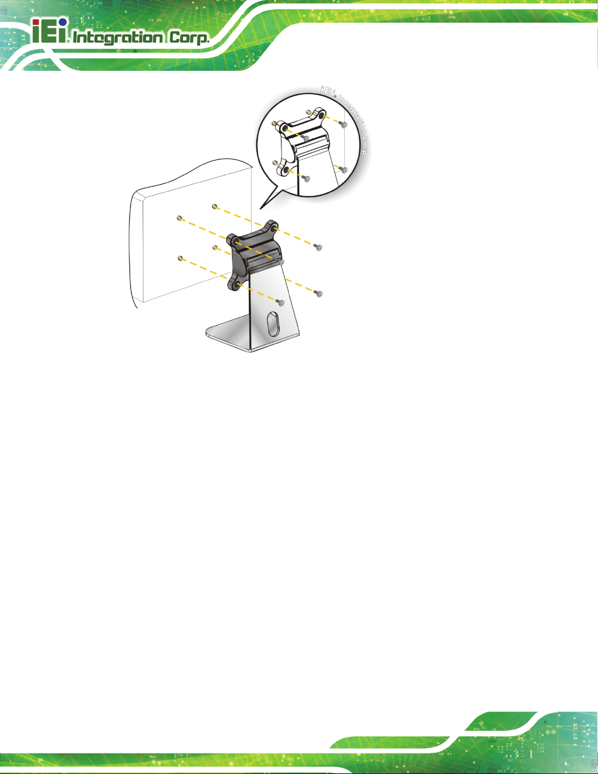
3.13.5 Stand Mounting
To mount the AFL3-W10A/12A/W15A-AL using the stand mounting kit, please follow the
steps below.
Step 1: Locate the screw holes on the rear of the AFL3-W10A/12A/W15A-AL. This is
where the bracket will be attached.
Step 2: Align the bracket with the screw holes.
Step 3: To secure the bracket to the AFL3-W10A/12A/W15A-AL insert the retention
screws into the screw holes and tighten them.
AFL3-W10A/12A/W15A-AL Panel PC
Page 50
Figure 3-36: Stand Mounting (Stand-A/Bxx)
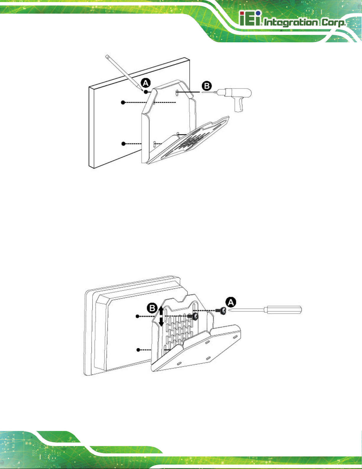
3.13.6 V-Stand Mounting (10.1" and 12.1" Models Only)
To mount the AFL3-W10A-AL or the AFL3-12A-AL using the optional V-Stand mounting
kit, please follow the steps below.
Step 1: Carefully mark the locations of the four V-Stand screw holes on the mounting
area. Drill four pilot holes at the marked locations for the V-Stand retention
screws.
AFL3-W10A/12A/W15A-AL Panel PC
Page 51
Figure 3-37: Drill Pilot Holes for V-Stand
Step 2: Align the screw holes on the V-Stand with the VESA mount screw holes on the
system rear panel.
Step 3: Insert the four VESA mount screws into the four screw holes on the system rear
panel. Adjust the V-Stand to a proper position.
Step 4: Tighten until the screw shank is secured against the rear panel.
Figure 3-38: Secure V-Stand to System
AFL3-W10A/12A/W15A-AL Panel PC
Page 52
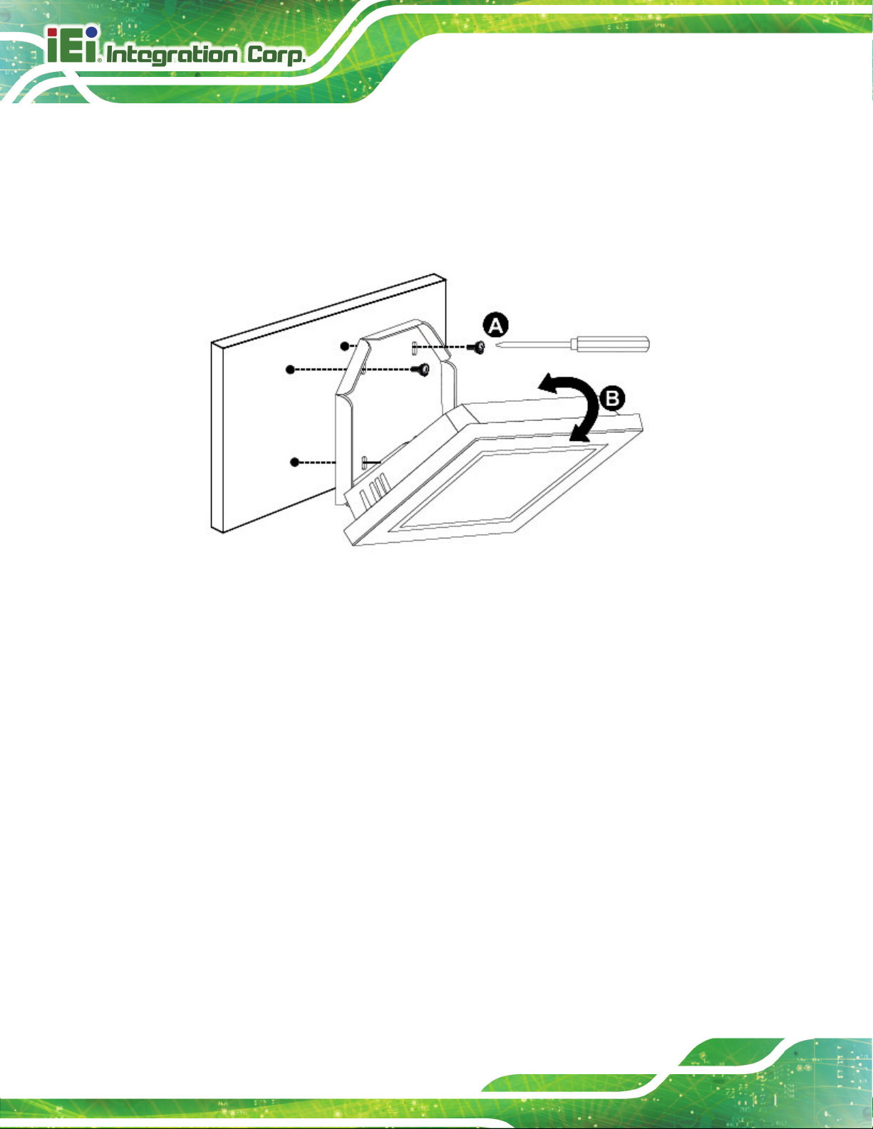
Step 5: Align the V-Stand screw holes with the pilot holes on the mounting area. Mount
the V-Stand by inserting the retention screws into the four pilot holes and
tightening them.
Step 6: Adjust the V-Stand to have a best viewing angle to operate the system.St ep 0:
Figure 3-39: Secure V-Stand to Mounting Area
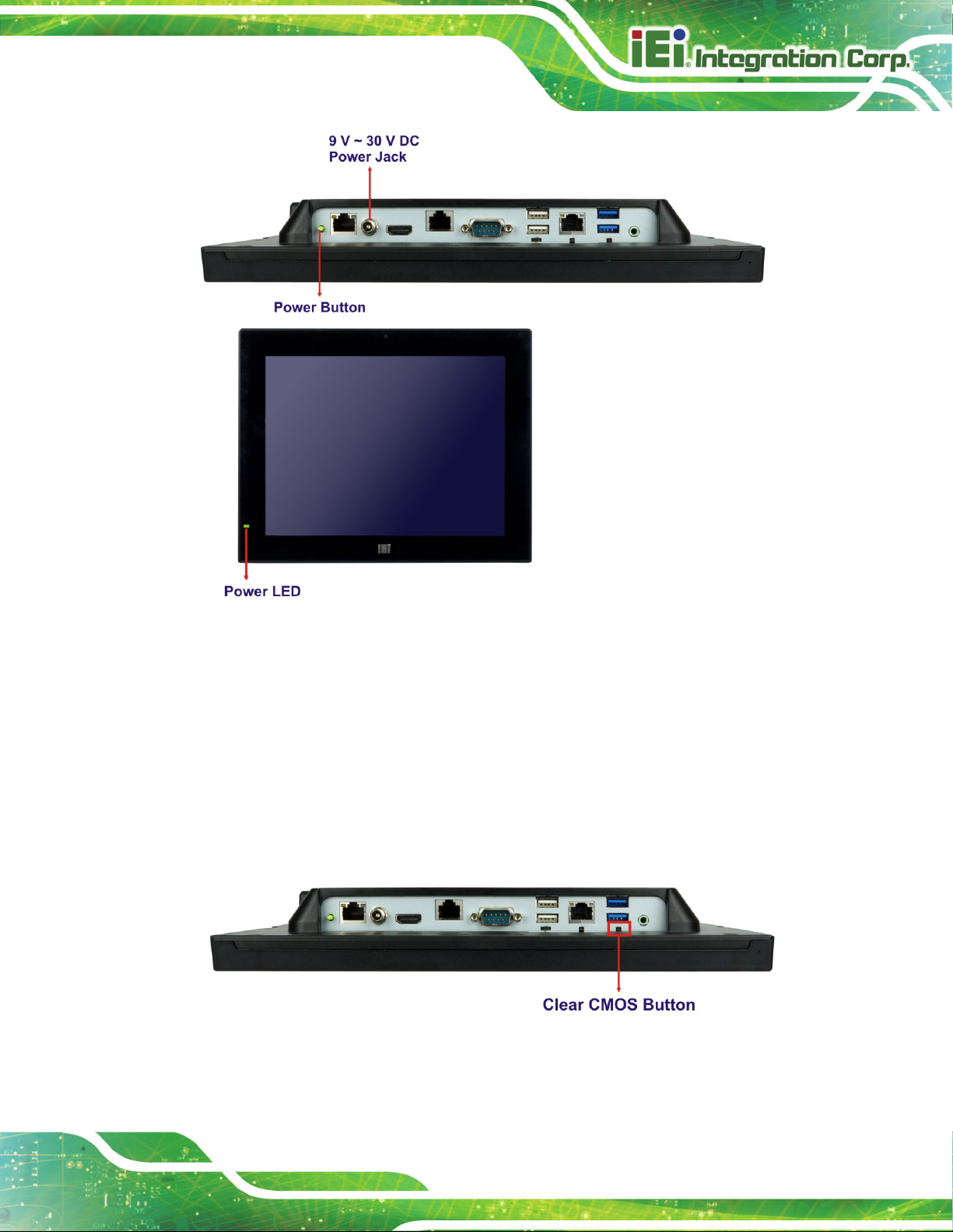
3.14 Powering On the System
To power on the system, follow the steps below:
Step 1: Connect the power cord to the power adapter. Connect the other end of the
power cord to a power source.
Step 2: Connect the power adapter to the power connector of the
AFL3-W10A/12A/W15A-AL.
Step 3: Locate the power button on the I/O panel.
Step 4: Hold down the power button until the power LED on the front panel turns on in
green. Step 0:
AFL3-W10A/12A/W15A-AL Panel PC
Page 53
Figure 3-40: Powering On the System
3.15 Clear CMOS
If the AFL3-W10A/12A/W15A-AL fails to boot due to improper BIOS settings, the clear
CMOS button clears the CMOS data and resets the system BIOS information. To do this,
push the clear CMOS button for three seconds, then restart the system. The clear CMOS
button location is shown in Figure 3-41.
Figure 3-41: Clear CMOS Button Location
AFL3-W10A/12A/W15A-AL Panel PC
Page 54
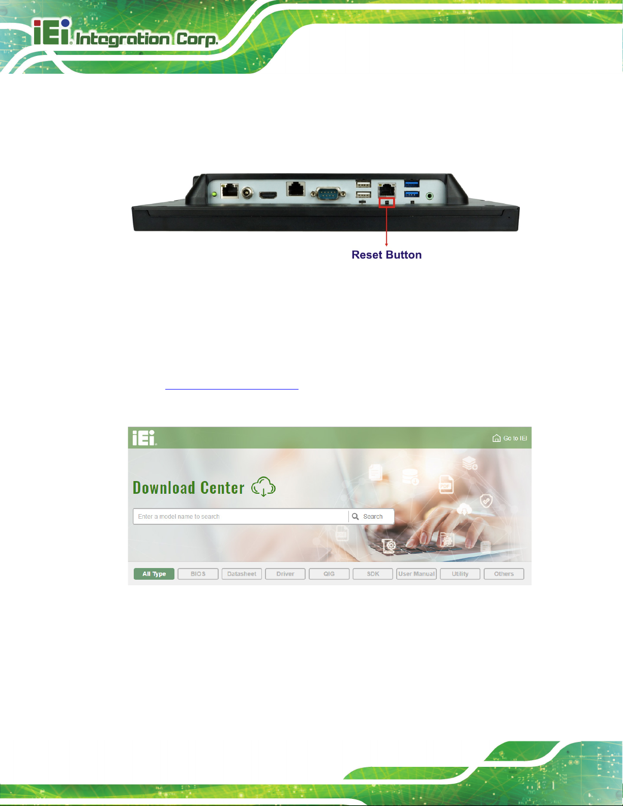
3.16 Reset the System
The reset button enables user to reboot the system when the system is turned on. The
reset button location is shown in Figure 3-42. Press the reset button to reboot the system.
Figure 3-42: Reset Button Location
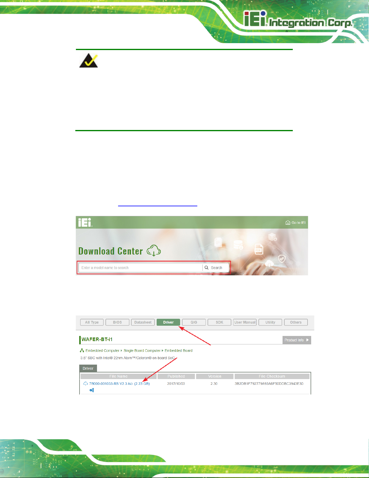
3.17 Software Installation
All the drivers for the AFL3-W10A/12A/W15A-AL are available on IEI Resource Download
Center (https://download.ieiworld.com). Type the model name and press Enter to find all
the relevant software, utilities, and documentation.
Figure 3-43: IEI Resource Download Center
AFL3-W10A/12A/W15A-AL Panel PC
Page 55
touchscreen and
NOTE:
The panel PC with projected capacitive type
Windows 7 (or later) OS does not require touch driver installation. This
is because there is a HID touch digitizer built-in driver in Windows 7 or
later.
3.17.1 Driver Download
To download drivers from IEI Resource Download Center, follow the steps below.
Step 1: Go to https://download.ieiworld.com. Type the model name and press Enter.
Step 2: All product-related software, utilities, and documentation will be listed. You can
choose Driver to filter the result.
AFL3-W10A/12A/W15A-AL Panel PC
Page 56
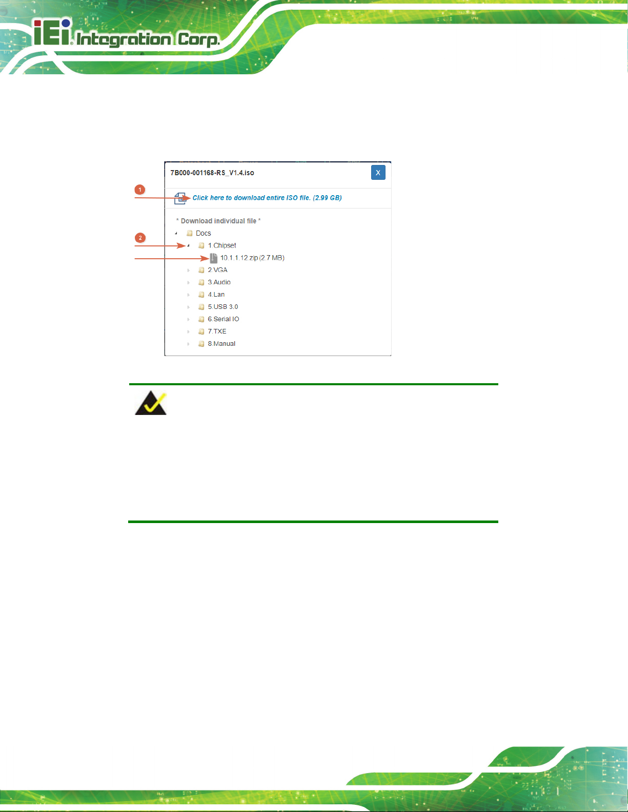
its content. On Windows 7 system, an additional tool (such as Virtual
Step 3: Click the driver file name on the page and you will be prompted with the
following window. You can download the entire ISO file (
arrow to find an individual driver and click the file name to download (
), or click the small
).
NOTE:
To install software from the downloaded ISO image file in Windows 8,
8.1 or 10, double-click the ISO file to mount it as a virtual drive to view
CD-ROM Control Panel from Microsoft) is needed to mount the file.

AFL3-W10A/12A/W15A-AL Panel PC
Page 57
Chapter
4
4 BIOS Setup
AFL3-W10A/12A/W15A-AL Panel PC
Page 58
ons may vary throughout the life cycle of the
4.1 Introduction
A licensed copy of the BIOS is preprogrammed into the ROM BIOS. The BIOS setup
program allows users to modify the basic system configuration. This chapter describes
how to access the BIOS setup program and the configuration options that may be
changed.
NOTE:
Some of the BIOS opti
product and are subject to change without prior notice.
4.1.1 Starting Setup
The UEFI BIOS is activated when the computer is turned on. The setup program can be
activated in one of two ways.
1. Press the DEL key as soon as the system is turned on or
2. Press the DEL key when the “Press DEL to enter SETUP” message
appears on the screen. 0.
If the message disappears before the DEL key is pressed, restart the computer and try
again.
4.1.2 Using Setup
Use the arrow keys to highlight items, press ENTER to select, use the PageUp and
PageDown keys to change entries, press F1 for help and press E
keys are shown in the following table.
SC to quit. Navigation
Key Function
Up arrow Move to the item above
Down arrow Move to the item below
AFL3-W10A/12A/W15A-AL Panel PC
Page 59
Left arrow Move to the item on the left hand side
Right arrow Move to the item on the right hand side
+ Increase the numeric value or make changes
- Decrease the numeric value or make changes
F1 key General help, only for Status Page Setup Menu and Option
Page Setup Menu
F2 key Load previous values.
F3 key Load optimized defaults
F4 key Save changes and Exit BIOS
Esc key Main Menu – Quit and do not save changes into CMOS
Status Page Setup Menu and Option Page Setup Menu --
Exit current page and return to Main Menu
Table 6-1: BIOS Navigation Keys
4.1.3 Getting Help
When F1 is pressed a small help window describing the appropriate keys to use and the
possible selections for the highlighted item appears. To exit the Help Window press E
the F1 key again.
4.1.4 Unable to Reboot after Configuration Changes
If the computer cannot boot after changes to the system configuration are made, CMOS
defaults. Use the clear CMOS button described in Section 3.15.
4.1.5 BIOS Menu Bar
The menu bar on top of the BIOS screen has the following main items:
Main – Changes the basic system configuration.
Advanced – Changes the advanced system settings.
SC or
Chipset – Changes the chipset settings.
Security – Sets User and Supervisor Passwords.
Boot – Changes the system boot configuration.

AFL3-W10A/12A/W15A-AL Panel PC
Page 60
Aptio Setup Utility – Copyright (C) 2019 American Megatrends, Inc.
Main
Advanced
Chipset
Security
Boot
Save & Exit
Version 2.18.1263. Copyright (C) 2019 American Megatrends, Inc.
The following sections completely describe the configuration options found in the menu
items at the top of the BIOS screen and listed above.
4.2 Main
The Main BIOS menu (BIOS Menu 1) appears when the BIOS Setup program is entered.
The Main menu gives an overview of the basic system information.
Save & Exit – Selects exit options and loads default settings
BIOS Information
BIOS Vendor American Megatrends
Core Version 5.12
Compliency UEFI 2.5; PI 1.4
Project Version Z574AR12.ROM
Build Date and Time 05/06/2019 11:52:01
iWDD Vendor iEi
iWDD Version Z574ER10.bin
Platform firmware Information
BXT SOC B1
MRC Version 0.56
PUNIT FW 2E
PMC FW 03.29
TXE FW 3.1.50.2238
ISH FW 4.1.0.3364
GOP 0.0.0036
Memory Information
Total Memory 4096 MB
Memory Speed 1600 MHz
Access Level Administrator
System Date [Wed 03/27/2019]
System Time [14:26:28]
Set the Date. Use Tab to
switch between Data
elements.
----------------------
: Select Screen
↑ ↓: Select Item
Enter Select
+/-: Change Opt.
F1: General Help
F2: Previous Values
F3: Optimized Defaults
F4: Save & Exit
ESC: Exit
BIOS Menu 1: Main

AFL3-W10A/12A/W15A-AL Panel PC
Page 61
Aptio Setup Utility – Copyright (C) 2019 American Megatrends, Inc.
Main
Advanced
Chipset
Security
Boot
Save & Exit
ESC: Exit
Version 2.18.1263. Copyright (C) 2019 American Megatrends, Inc.
System Date [xx/xx/xx]
Use the System Date option to set the system date. Manually enter the day, month and
year.
System Time [xx:xx:xx]
Use the System Time option to set the system time. Manually enter the hours, minutes
and seconds.
4.3 Advanced
Use the Advanced menu (BIOS Menu 2) to configure the CPU and peripheral devices
through the following sub-menus:
WARNING:
Setting the wrong values in the sections below may cause the system
to malfunction. Make sure that the settings made are compatible with
the hardware.
> ACPI Settings
> F81866 Super IO Configuration
> iWDD H/M Monitor
> USB Configuration
> CPU Configuration
> RTC Wake Settings
> Power Saving Configuration
> Serial Port Console Redirection
> iEi Feature
System ACPI Parameters.
----------------------
: Select Screen
↑ ↓: Select Item
Enter Select
+/-: Change Opt.
F1: General Help
F2: Previous Values
F3: Optimized Defaults
F4: Save & Exit
BIOS Menu 2: Advanced

AFL3-W10A/12A/W15A-AL Panel PC
Page 62
Aptio Setup Utility – Copyright (C) 2019 American Megatrends, Inc.
Advanced
Select the highest ACPI
ESC: Exit
Version 2.18.1263. Copyright (C) 2019 American Megatrends, Inc.
S3 (Suspend to
off. Power to the RAM is maintained. The
returns slower to a working state, but
4.3.1 ACPI Settings
The ACPI Settings menu (BIOS Menu 3) configures the Advanced Configuration and
Power Interface (ACPI) options.
ACPI Settings
ACPI Sleep State [S3 (Suspend to RAM)]
sleep state the system
will enter, when the
SUSPEND button is
pressed.
----------------------
: Select Screen
↑ ↓: Select Item
Enter Select
+/-: Change Opt.
F1: General Help
F2: Previous Values
F3: Optimized Defaults
F4: Save & Exit
ACPI Sleep State [S3 (Suspend to RAM)]
Use the ACPI Sleep State option to specify the sleep state the system enters when it is
not being used.
BIOS Menu 3: ACPI Settings
RAM)
D
EFAULT
The caches are flushed and the CPU is powered
computer
more power is saved.

AFL3-W10A/12A/W15A-AL Panel PC
Page 63
Aptio Setup Utility – Copyright (C) 2019 American Megatrends, Inc.
Advanced
ESC: Exit
Version 2.18.1263. Copyright (C) 2019 American Megatrends, Inc.
4.3.2 F81866 Super IO Configuration
Use the F81866 Super IO Configuration menu (BIOS Menu 4) to set or change the
configurations for the serial ports.
F81866 Super IO Configuration
Super IO Chip F81866
> Serial Port 1 Configuration
> Serial Port 2 Configuration
Case Open Detection [Disabled]
BIOS Menu 4: F81866 Super IO Configuration
Case Open Detection [Disabled]
Use the Case Open Detection option to enable or disable case open detection.
Disabled DEFAU LT
Disable case open detection
Set Parameters of Serial
Port 1 (COMA)
---------------------
: Select Screen
↑ ↓: Select Item
Enter Select
+/-: Change Opt.
F1: General Help
F2: Previous Values
F3: Optimized Defaults
F4: Save & Exit
Enabled
Enable case open detection

AFL3-W10A/12A/W15A-AL Panel PC
Page 64
Aptio Setup Utility – Copyright (C) 2019 American Megatrends, Inc.
Advanced
ESC: Exit
Version 2.18.1263. Copyright (C) 2019 American Megatrends, Inc.
port address is 3F8h and the
Serial Port I/O port address is 3F8h and the
4.3.2.1 Serial Port n Configuration
Use the Serial Port n Configuration menu (BIOS Menu 5) to configure the serial port n.
Serial Port 1 Configuration
Serial Port [Enabled]
Device Settings IO=3F8h; IRQ=4
Change Settings [IO=3F8h; IRQ=4]
BIOS Menu 5: Serial Port n Configuration Menu
4.3.2.1.1 Serial Port 1 Configuration
Serial Port [Enabled]
Use the Serial Port option to enable or disable the serial port.
Enable or Disable Serial
Port (COM)
---------------------
: Select Screen
↑ ↓: Select Item
Enter Select
+/-: Change Opt.
F1: General Help
F2: Previous Values
F3: Optimized Defaults
F4: Save & Exit
Disabled
Enabled DEFAULT
Change Settings [Auto]
Use the Change Settings option to change the serial port IO port address and interrupt
address.
IO=3F8h; IRQ=4 DE FAULT
IO=3F8h;
IRQ=3, 4, 10
Disable the serial port
Enable the serial port
Serial Port I/O
interrupt address is IRQ4
interrupt address is IRQ3, 4, 10

AFL3-W10A/12A/W15A-AL Panel PC
Page 65
Serial Port I/O port address is 2F8h and the
Serial Port I/O port address is 3E8h and the
Serial Port I/O port address is 2E8h and the
F8h and the
Serial Port I/O port address is 3F8h and the
Serial Port I/O port address is 2F8h and the
Serial Port I/O port address is 3E8h and the
I/O port address is 2E8h and the
IO=2F8h;
IRQ=3, 4, 10
IO=3E8h;
IRQ=3, 4, 10
IO=2E8h;
IRQ=3, 4, 10
4.3.2.1.2 Serial Port 2 Configuration
Serial Port [Enabled]
Use the Serial Port option to enable or disable the serial port.
Disabled
Enabled DEFAULT
Change Settings [Auto]
interrupt address is IRQ3, 4, 10
interrupt address is IRQ3, 4, 10
interrupt address is IRQ3, 4, 10
Disable the serial port
Enable the serial port
Use the Change Settings option to change the serial port IO port address and interrupt
address.
IO=2F8h; IRQ=3 DE FA ULT
IO=3F8h;
IRQ=3, 4, 10
IO=2F8h;
IRQ=3, 4, 10
IO=3E8h;
IRQ=3, 4, 10
IO=2E8h;
IRQ=3, 4, 10
Serial Port I/O port address is 2
interrupt address is IRQ3
interrupt address is IRQ3, 4, 10
interrupt address is IRQ3, 4, 10
interrupt address is IRQ3, 4, 10
Serial Port
interrupt address is IRQ3, 4, 10
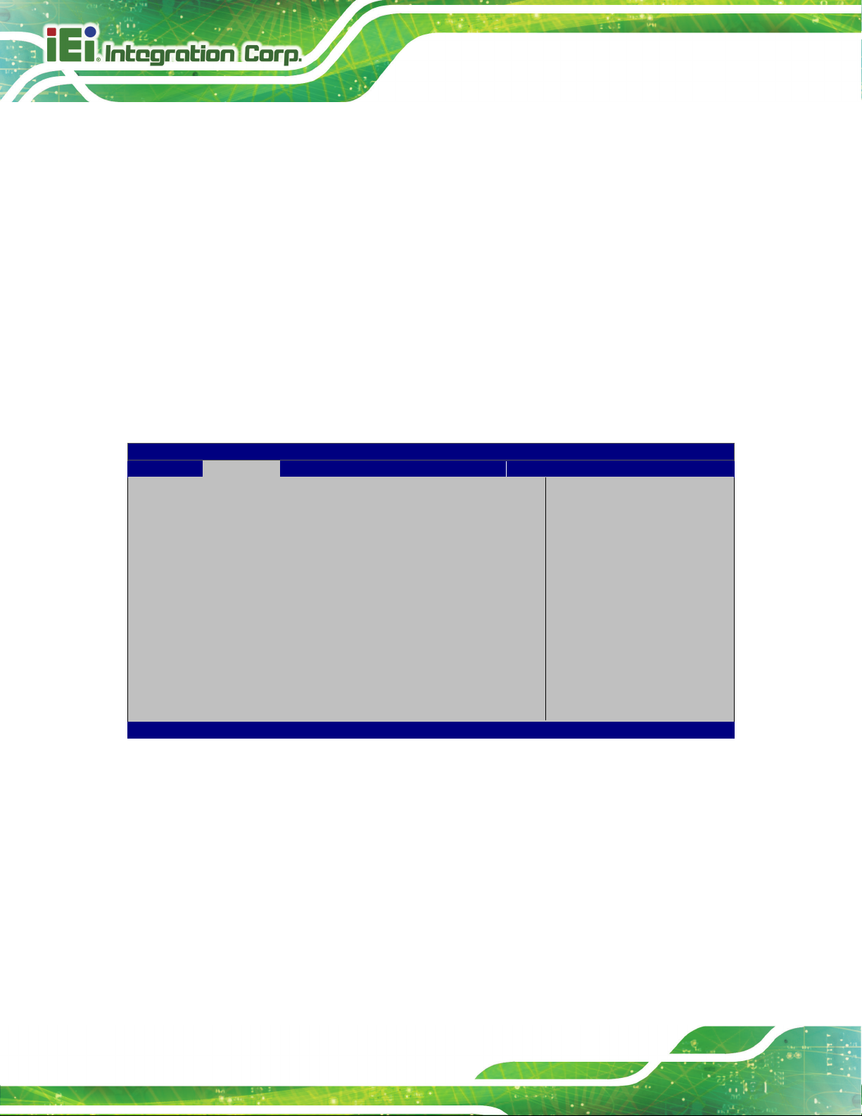
AFL3-W10A/12A/W15A-AL Panel PC
Page 66
Aptio Setup Utility – Copyright (C) 2019 American Megatrends, Inc.
Advanced
ESC: Exit
Version 2.18.1263. Copyright (C) 2019 American Megatrends, Inc.
Transfer Mode [RS232]
Use the Transfer Mode option to select the Serial Port 2 signaling mode.
RS422
RS232 DE FAULT
RS485
Serial Port 6 signaling mode is RS-422
Serial Port 6 signaling mode is RS-232
Serial Port 6 signaling mode is RS-485
4.3.3 iWDD H/W Monitor
The iWDD H/W Monitor menu (BIOS Menu 6) shows the operating temperatures and
voltages.
PC Health Status
System temperature :+35 °C
CPU_CORE :+0.865 V
+5V :+5.005 V
+12V :+11.741 V
+DDR :+1.348 V
+5VSB :+4.991 V
+3.3V :+3.296 V
+3.3VSB :+3.311 V
---------------------
: Select Screen
↑ ↓: Select Item
Enter Select
+/-: Change Opt.
F1: General Help
F2: Previous Values
F3: Optimized Defaults
F4: Save & Exit
BIOS Menu 6: iWDD H/W Monitor
Hardware Health Status
The following system parameters and values are shown. The system parameters that are
monitored are:
System Temperature
Voltages:
o CPU_CORE
o +5V
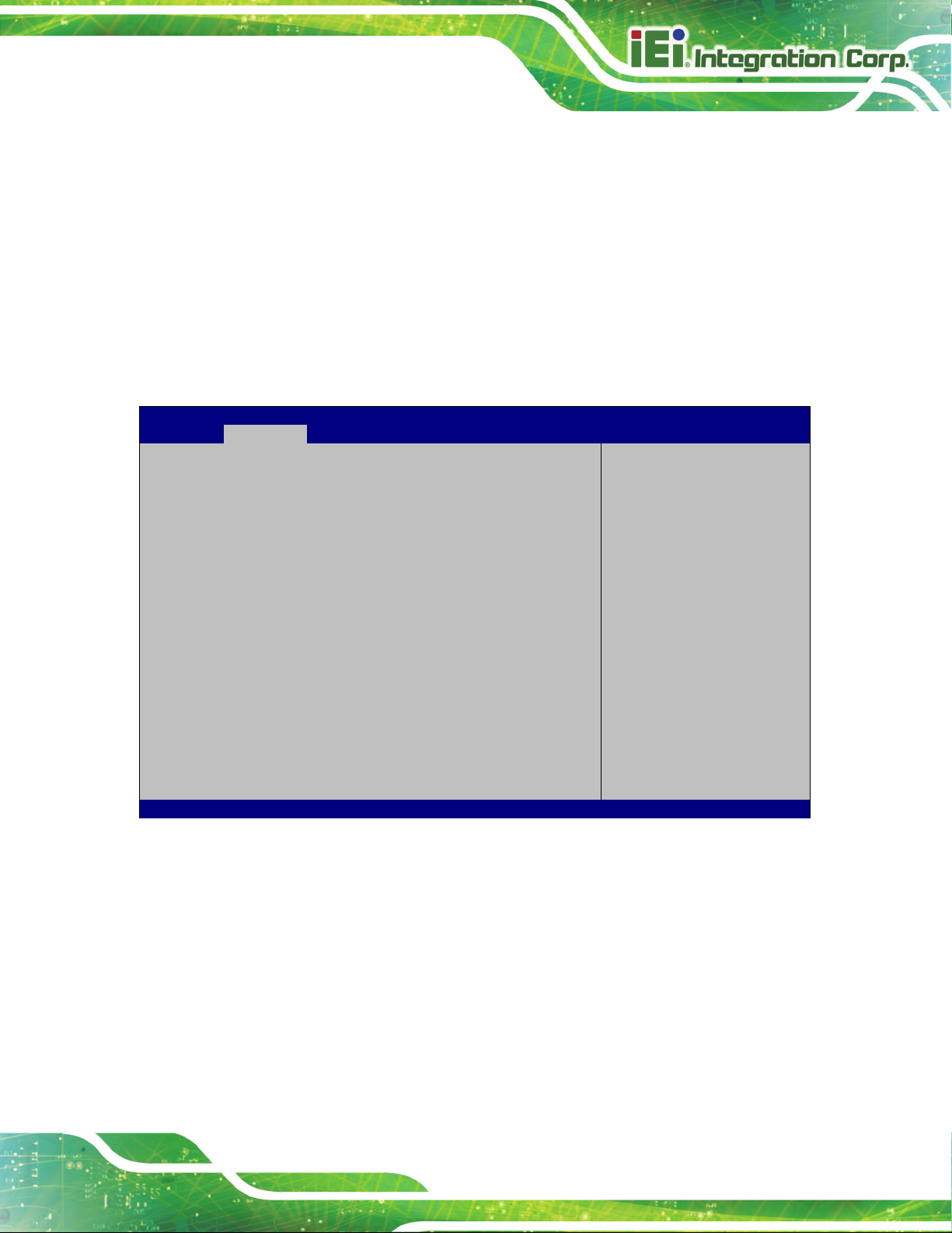
AFL3-W10A/12A/W15A-AL Panel PC
Page 67
Aptio Setup Utility – Copyright (C) 2019 American Megatrends, Inc.
Advanced
disables legacy support
ESC: Exit
Version 2.18.1263. Copyright (C) 2019 American Megatrends, Inc.
o +12V
o +DDR
o +5VSB
o +3.3V
o +3.3VSB
4.3.4 USB Configuration
Use the USB Configuration menu (BIOS Menu 7) to read USB configuration information
and configure the USB settings.
USB Configuration
USB Devices:
1 Keyboard, 1 Mouse, 1 Point
Legacy USB Support [Enabled]
BIOS Menu 7: USB Configuration
USB Devices
Enables Legacy USB
support. AUTO option
if no USB devices are
connected. DISABLE
option will keep USB
devices available only
for EFI applications.
---------------------
: Select Screen
↑ ↓: Select Item
Enter Select
+/-: Change Opt.
F1: General Help
F2: Previous Values
F3: Optimized Defaults
F4: Save & Exit
The USB Devices Enabled field lists the USB devices that are enabled on the system
Legacy USB Support [Enabled]
Use the Legacy USB Support BIOS option to enable USB mouse and USB keyboard
support. Normally if this option is not enabled, any attached USB mouse or USB keyboard
does not become available until a USB compatible operating system is fully booted with all
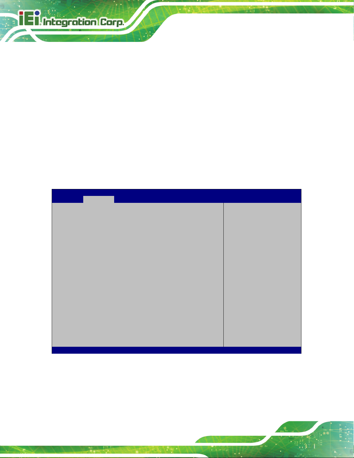
AFL3-W10A/12A/W15A-AL Panel PC
Page 68
Aptio Setup Utility – Copyright (C) 2019 American Megatrends, Inc.
Advanced
Version 2.18.1263. Copyright (C) 2019 American Megatrends, Inc.
USB drivers loaded. When this option is enabled, any attached USB mouse or USB
keyboard can control the system even when there is no USB driver loaded onto the
system.
Enabled DEFAULT
Disabled
Auto
Legacy USB support enabled
Legacy USB support disabled
Legacy USB support disabled if no USB devices are
connected
4.3.5 CPU Configuration
Use the CPU Configuration (BIOS Menu 8) to view detailed CPU specifications and
configure the CPU.
CPU Configuration
Intel(R) Celeron(R) CPU J3455 @ 1.50GHz
CPU Signature 506C9
Microcode Patch 2E
Max CPU Speed 1500 MHz
Min CPU Speed 800 MHz
Processor Cores 4
Intel HT Technology Not Supported
Intel VT-x Technology Supported
L1 Data Cache 24 KB x 4
L1 Code Cache 32 KB x 4
L2 Cache 1024 KB x 2
L3 Cache Not Present
EIST [Enabled]
C-States [Disabled]
Intel Virtualization Technology [Disabled]
VT-d [Disabled]
Enable/Disable Intel
SpeedStep
----------------------
: Select Screen
↑ ↓: Select Item
Enter Select
+/-: Change Opt.
F1: General Help
F2: Previous Values
F3: Optimized Defaults
F4: Save & Exit
ESC: Exit
BIOS Menu 8: CPU Configuration

AFL3-W10A/12A/W15A-AL Panel PC
Page 69
EIST [Enabled]
Use the EIST option to enable or disable the Intel
®
Speed Step Technology.
Disabled
Enabled DEFAU LT
C-States [Disabled]
Use the C-States option to enable or disable the C-states.
Disabled DEFAULT
Enabled
Intel Virtualization Technology [Disabled]
Use the Intel Virtualization Technology option to enable or disable virtualization on the
system. When combined with third party software, Intel
several OSs to run on the same system at the same time.
Disabled DEFAULT
Disables the Intel
Enables the Intel
Disables the C-state
Enables the C-state
Disables Intel
®
Speed Step Technology.
®
Speed Step Technology.
®
Virtualization technology allows
®
Virtualization Technology.
Enabled
VT-d [Disabled]
Use the VT-d BIOS option to enable or disabled VT-d support.
Disabled DEFAU LT
Enabled
Enables Intel
Disable VT-d support.
Enable VT-d support.
®
Virtualization Technology.
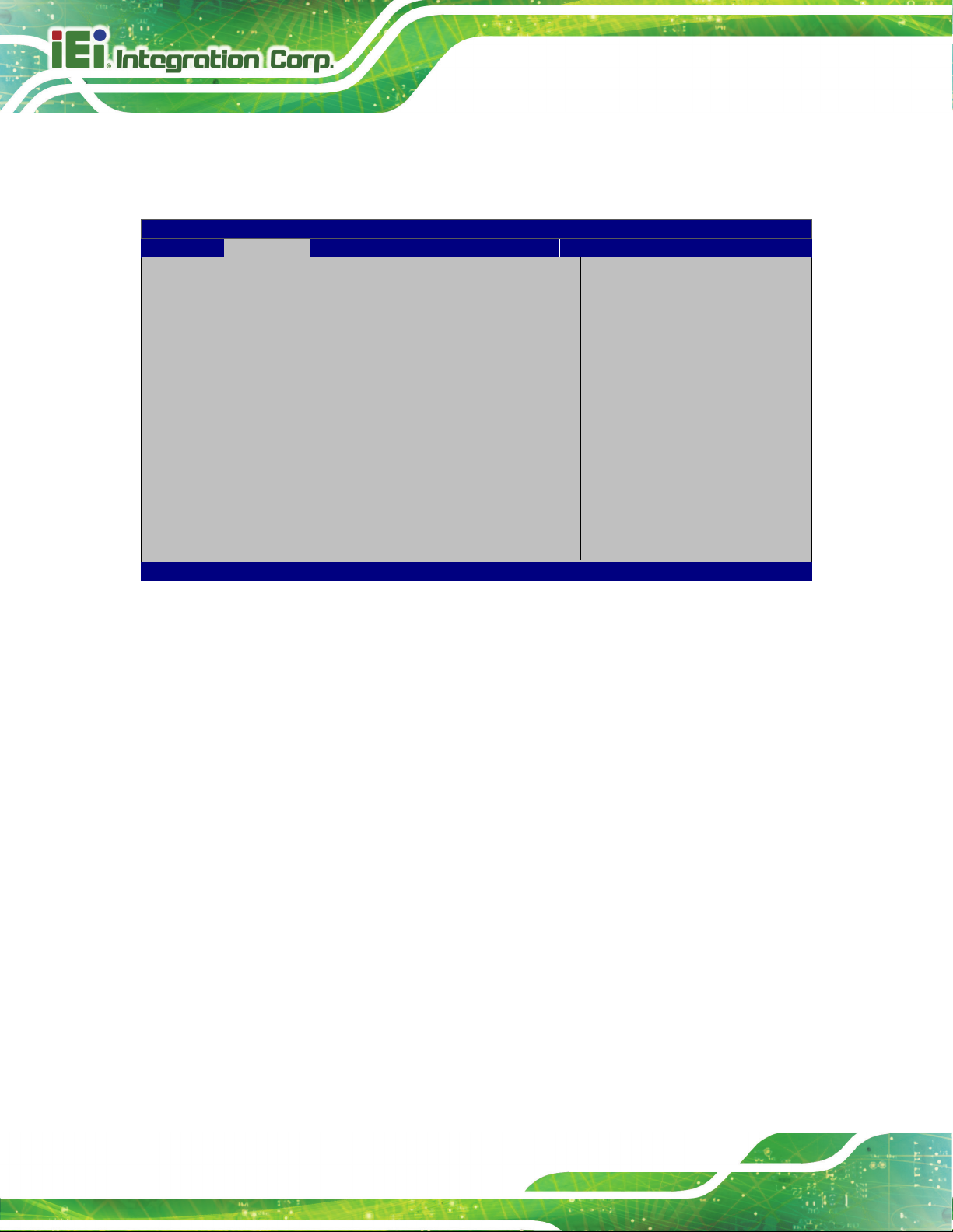
AFL3-W10A/12A/W15A-AL Panel PC
Page 70
Aptio Setup Utility – Copyright (C) 2019 American Megatrends, Inc.
Advanced
ESC Exit
Version 2.18.1263. Copyright (C) 2019 American Megatrends, Inc.
The real time clock (RTC) cannot generate a wake
If selected, the following appears with values that
4.3.6 RTC Wake Settings
The RTC Wake Settings menu (BIOS Menu 9) configures RTC wake event.
Wake system with Fixed Time [Disabled]
BIOS Menu 9: RTC Wake Settings
Wake System with Fixed Time [Disabled]
Use the Wake System with Fixed Time option to specify the time the system should be
roused from a suspended state.
Enable or disable System
wake on alarm event. When
enabled, System will wake
on the dat::hr::min::sec
specified
----------------------
: Select Screen
↑ ↓: Select Item
Enter Select
F1 General Help
F2 Previous Values
F3 Optimized Defaults
F4 Save
Disabled DEFAU LT
Enabled
event
can be selected:
*Wake up every day
*Wake up date
*Wake up hour
*Wake up minute
*Wake up second
After setting the alarm, the computer turns itself on
from a suspend state when the alarm goes off.
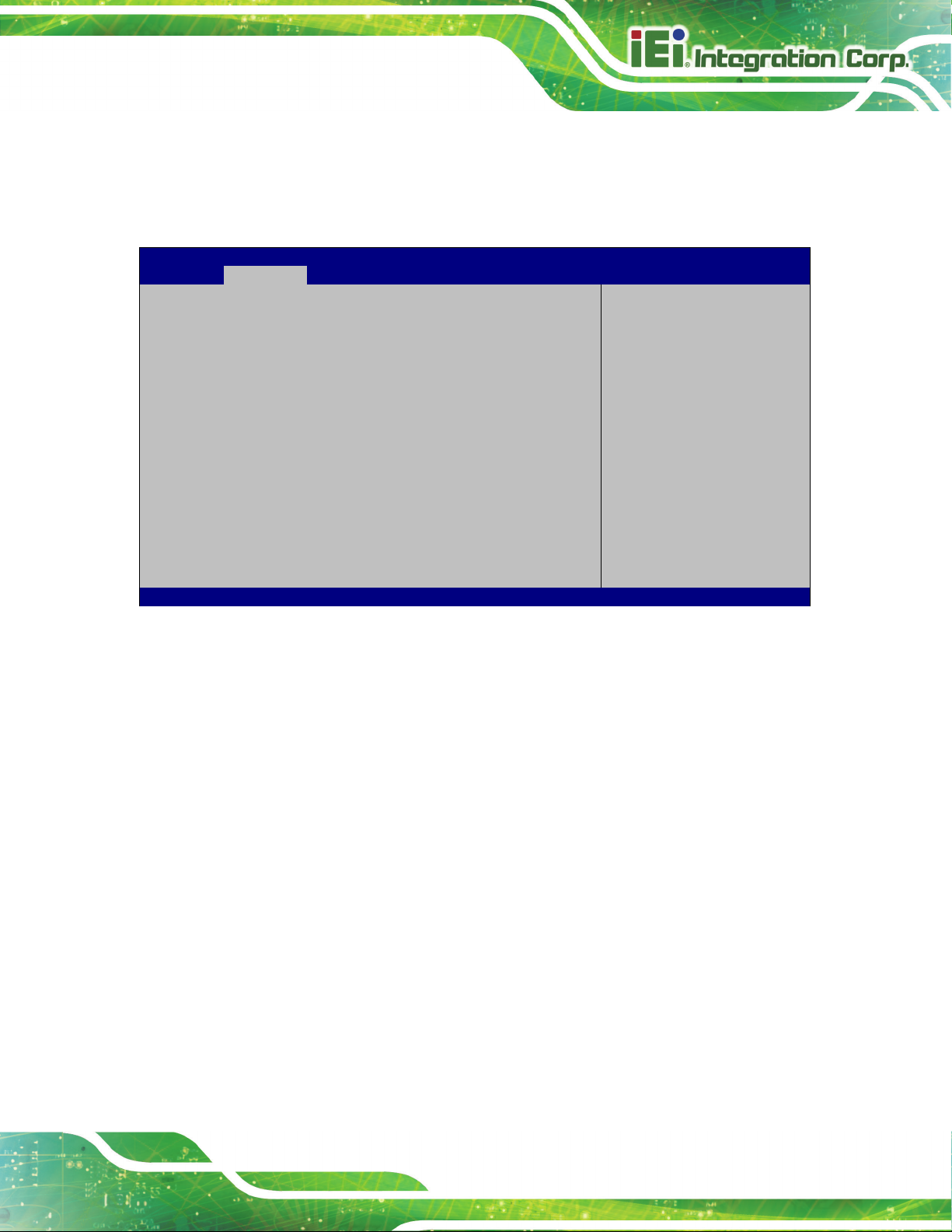
AFL3-W10A/12A/W15A-AL Panel PC
Page 71
Aptio Setup Utility – Copyright (C) 2019 American Megatrends, Inc.
Advanced
ESC Exit
Version 2.18.1263. Copyright (C) 2019 American Megatrends, Inc.
4.3.7 Power Saving Configuration
Use the Power Saving Configuration menu (BIOS Menu 10) to configure system to
reduce power consumption in system off state.
Power Saving Configuration
Power Saving Function [Disabled]
BIOS Menu 10: Power Saving Configuration
Power Saving Function(ERP) [Disabled]
Use the Power Saving Function BIOS option to enable or disable the power saving
function.
Enable or Disable to
reduce power consumption
in system off state.
---------------------
: Select Screen
↑ ↓: Select Item
Enter Select
F1 General Help
F2 Previous Values
F3 Optimized
Defaults
F4 Save
Disabled DEFAULT
Enabled
Power saving function is disabled.
Power saving function is enabled. It will reduce power
consumption when the system is off.
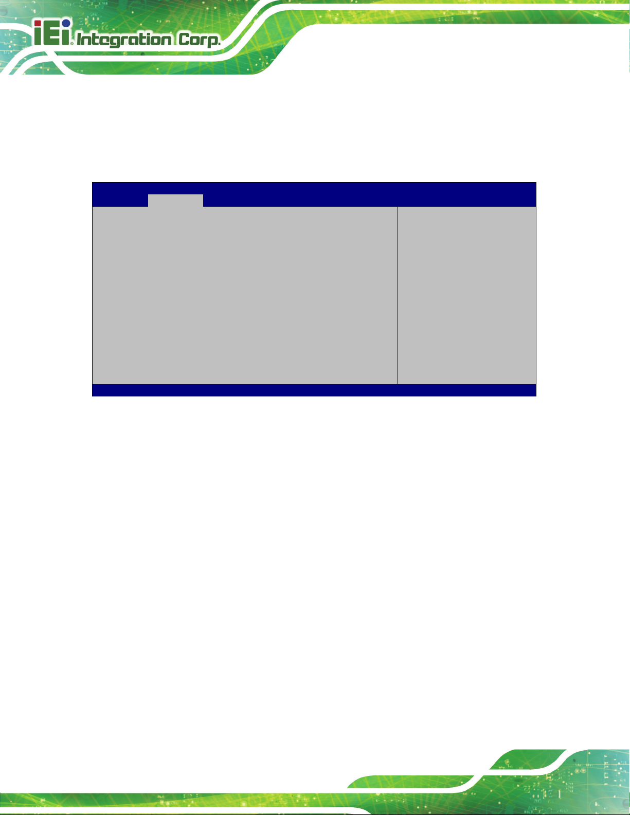
AFL3-W10A/12A/W15A-AL Panel PC
Page 72
Aptio Setup Utility – Copyright (C) 2019 American Megatrends, Inc.
Advanced
ESC: Exit
Version 2.18.1263. Copyright (C) 2019 American Megatrends, Inc.
4.3.8 Serial Port Console Redirection
The Serial Port Console Redirection menu (BIOS Menu 11) allows the console
redirection options to be configured. Console redirection allows users to maintain a
system remotely by re-directing keyboard input and text output through the serial port.
COM1
Console Redirection [Disabled]
> Console Redirection Settings
COM2
Console Redirection [Disabled]
> Console Redirection Settings
Legacy Console Redirection
> Legacy Console Redirection Settings
BIOS Menu 11: Serial Port Console Redirection
Console Redirection [Disabled]
Use Console Redirection option to enable or disable the console redirection function.
Disabled DEFAU LT
Disabled the console redirection function
Console Redirection
Enable or Disable.
---------------------
: Select Screen
↑ ↓: Select Item
Enter Select
+/-: Change Opt.
F1: General Help
F2: Previous Values
F3: Optimized Defaults
F4: Save & Exit
Enabled
Enabled the console redirection function

AFL3-W10A/12A/W15A-AL Panel PC
Page 73
Aptio Setup Utility – Copyright (C) 2017 American Megatrends, Inc.
Advanced
Version 2.18.1263. Copyright (C) 2017 American Megatrends, Inc.
4.3.8.1 Legacy Console Redirection Settings
The Legacy Console Redirection Settings menu (BIOS Menu 12) allows the legacy
console redirection options to be configured.
Legacy Serial Redirection Port [COM1]
BIOS Menu 12: Legacy Console Redirection Settings
Legacy Serial Redirection Port [COM1]
Use the Legacy Serial Redirection Port option to specify a COM port to display
redirection of legacy OS and legacy OPROM messages. The options include:
Select a COM port to
display redirection of
Legacy OS and Legacy
OPROM Messages
---------------------
: Select Screen
↑ ↓: Select Item
Enter Select
F1 General Help
F2 Previous Values
F3 Optimized
Defaults
F4 Save
ESC Exit
COM1 D
COM2
EFAULT
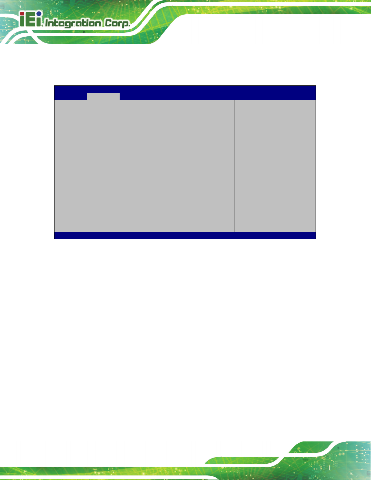
AFL3-W10A/12A/W15A-AL Panel PC
Page 74
Aptio Setup Utility – Copyright (C) 2019 American Megatrends, Inc.
Advanced
crashes. Please install
service before enabling
ESC: Exit
Version 2.18.1263. Copyright (C) 2019 American Megatrends, Inc.
4.3.9 iEi Feature
Use the iEi Feature menu (BIOS Menu 13) to configure One Key Recovery function.
iEi Feature
Auto Recovery Function [Disabled]
BIOS Menu 13: iEi Feature
Auto Recovery Function [Disabled]
Use the Auto Recovery Function BIOS option to enable or disable the auto recovery
Auto Recovery Function
Reboot and recover
system automatically
within 10 min, when OS
Auto Recovery API
this function.
---------------------
: Select Screen
↑ ↓: Select Item
Enter: Select
+/-: Change Opt.
F1: General Help
F2: Previous Values
F3: Optimized Defaults
F4: Save & Exit
function of the IEI One Key Recovery.
Disabled DEFAU LT
Enabled
Auto recovery function disabled
Auto recovery function enabled
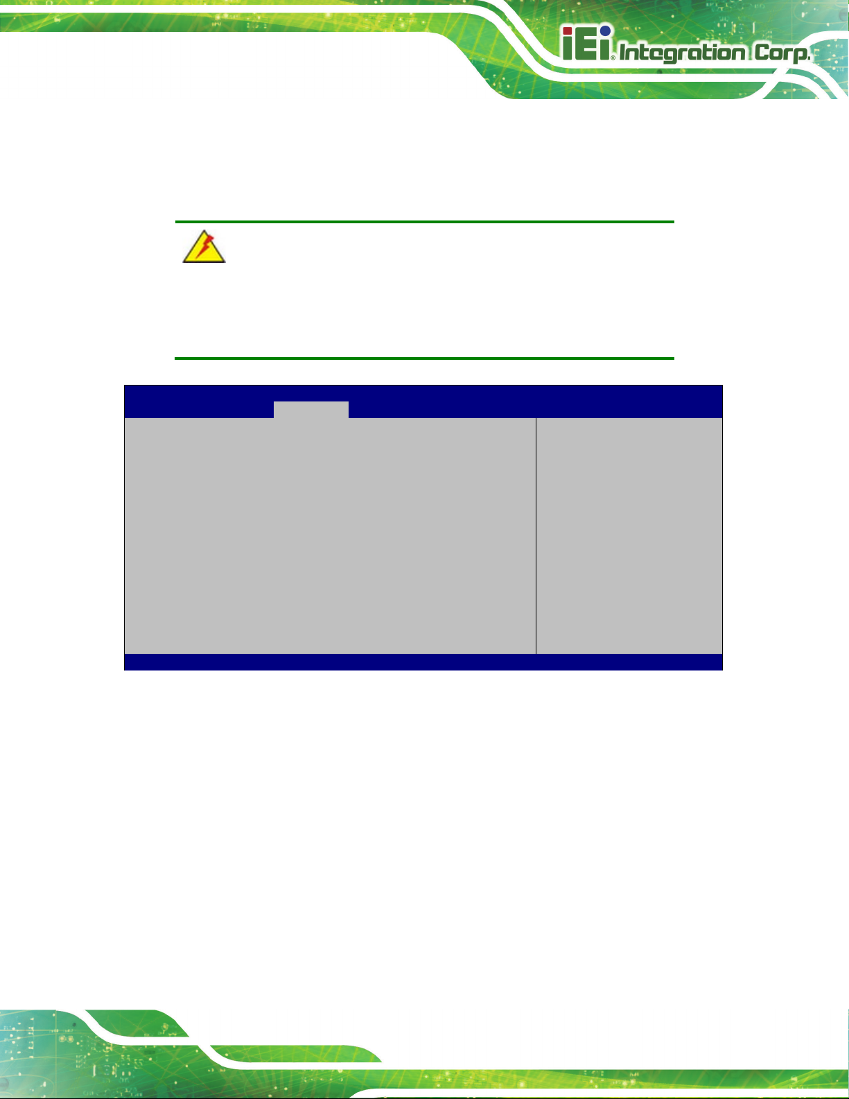
AFL3-W10A/12A/W15A-AL Panel PC
Page 75
Aptio Setup Utility – Copyright (C) 2019 American Megatrends, Inc.
Main
Advanced
Chipset
Security
Boot
Save & Exit
Version 2.18.1263. Copyright (C) 2019 American Megatrends, Inc.
4.4 Chipset
Use the Chipset menu (BIOS Menu 14) to access the North Bridge, South Bridge, and
Integrated Graphics configuration menus.
WARNING!
Setting the wrong values for the Chipset BIOS selections in the Chipset
BIOS menu may cause the system to malfunction.
> North Bridge
> South Bridge
BIOS Menu 14: Chipset
North Bridge Parameters
---------------------
: Select Screen
↑ ↓: Select Item
Enter Select
+ - Change Opt.
F1 General Help
F2 Previous Values
F3 Optimized Defaults
F4 Save & Exit
ESC Exit

AFL3-W10A/12A/W15A-AL Panel PC
Page 76
Aptio Setup Utility – Copyright (C) 2019 American Megatrends, Inc.
Chipset
Version 2.18.1263. Copyright (C) 2019 American Megatrends, Inc.
Aptio Setup Utility – Copyright (C) 2019 American Megatrends, Inc.
Chipset
selected as the Primary
Video Adaptor. Disable:
ESC Exit
Version 2.18.1263. Copyright (C) 2019 American Megatrends, Inc.
4.4.1 North Bridge Configuration
Use the North Bridge menu (BIOS Menu 15) to configure the north bridge chipset.
> Intel IGD Configuration
> LCD Control
Memory Information
Total Memory 4096 MB (LPDDR3)
On Board Memory 4096 MB (LPDDR3)
BIOS Menu 15: North Bridge Configuration
4.4.1.1 Internal IGD Configuration
Use the Internal IGD Configuration (BIOS Menu 16) menu to set the integrated graphics.
Intel IGD Configuration
---------------------
: Select Screen
↑ ↓: Select Item
Enter Select
+ - Change Opt.
F1 General Help
F2 Previous Values
F3 Optimized Defaults
F4 Save & Exit
ESC Exit
IGD Configuration
Primary Display [IGD]
DVMT Pre-Allocated [256M]
DVMT Total Gfx Mem [MAX]
BIOS Menu 16: Internal IGD Configuration
Enable: Enable
Integrated Graphics
Device (IGD) when
Always disable IGD
---------------------
: Select Screen
↑ ↓: Select Item
Enter Select
+ - Change Opt.
F1 General Help
F2 Previous Values
F3 Optimized Defaults
F4 Save & Exit

AFL3-W10A/12A/W15A-AL Panel PC
Page 77
Primary Display [IGD]
Use the Primary Display option to select the graphics controller used as the primary boot
device. Configuration option is listed below:
IGD
DVMT Pre-Allocated [256MB]
Use the DVMT Pre-Allocated option to set the amount of system memory allocated to the
integrated graphics processor when the system boots. The system memory allocated can
then only be used as graphics memory, and is no longer available to applications or the
operating system. Configuration options are listed below:
64M
128M
256M D
512M
DVMT Total Gfx Mem [MAX]
Use the DVMT Total Gfx Mem option to select DVMT5.0 total graphic memory size used
by the internal graphic device. The following options are available:
DE FAULT
EFAULT
128M
256M
MAX D
EFAULT

AFL3-W10A/12A/W15A-AL Panel PC
Page 78
Aptio Setup Utility – Copyright (C) 2019 American Megatrends, Inc.
Chipset
Select the Video Device
which will be activated
ESC: Exit
Version 2.18.1263. Copyright (C) 2019 American Megatrends, Inc.
4.4.1.2 LCD Control
Use the LCD Control submenu (BIOS Menu 17) to select a display device which will be
activated during POST.
LCD Control
Primary IGFX Boot Display [Auto]
LVDS Panel Detect [INSTALLED]
Panel Setting
Backlight Control Mode [LED]
Backlight Control Type [PWM]
during POST. This has no
effect if external
graphics present.
Secondary boot display
selection will appear
based on your selection.
VGA modes will be
supported only on
primary display.
---------------------
: Select Screen
↑ ↓: Select Item
Enter Select
+/-: Change Opt.
F1: General Help
F2: Previous Values
F3: Optimized Defaults
F4: Save & Exit
Primary IGFX Boot Display [Auto]
Use the Primary IGFX Boot Display option to select the display device used by the
system when it boots.
BIOS Menu 17: LCD Control
Auto
LVDS
HDMI1
DEFAULT

AFL3-W10A/12A/W15A-AL Panel PC
Page 79
Aptio Setup Utility – Copyright (C) 2019 American Megatrends, Inc.
Chipset
ESC: Exit
Version 2.18.1263. Copyright (C) 2019 American Megatrends, Inc.
Backlight Control Mode [LED]
Use the Backlight Control Mode option to specify the backlight control mode.
Configuration option is listed below.
LED D
Backlight Control Type [ PWM]
Use the Backlight Control Type option to specify the backlight control type.
Configuration option is listed below.
PWM D
EFAU LT
EFAULT
4.4.2 South Bridge Configuration
Use the South Bridge Configuration menu (BIOS Menu 15) to configure the south
bridge chipset.
Auto Power Button Function [Disable (ATX)]
> HD-Audio Configuration
> PCI Express Configuration
> SATA Configuration
Restore AC Power Loss [Last State]
USB Power SW1 [+5V DUAL]
HD-Audio Configuration
Settings
---------------------
: Select Screen
↑ ↓: Select Item
Enter Select
+/-: Change Opt.
F1: General Help
F2: Previous Values
F3: Optimized Defaults
F4: Save & Exit
BIOS Menu 18: South Bridge Configuration

AFL3-W10A/12A/W15A-AL Panel PC
Page 80
Restore on AC Power Loss [Last State]
Use the Restore on AC Power Loss BIOS option to specify what state the system
returns to if there is a sudden loss of power to the system.
Power Off
Power On
Last State DEFA ULT
USB Power SW1 [+5V DUAL]
Use the USB Power SW1 BIOS option to configure whether to provide power to the
external USB 3.0 connectors when the system is in S3/S4 sleep state. This option is valid
only when the above Power Saving Function BIOS option (see Section 4.3.7) is
disabled.
+5V DUAL DEFAU LT
+5V
The system remains turned off
The system turns on
The system returns to its previous state. If it was on, it
turns itself on. If it was off, it remains off.
Power is provided to the external USB 3.0 connectors
when the system is in S3/S4 sleep state
Power is not provided to the external USB 3.0
connectors when the system is in S3/S4 sleep state

AFL3-W10A/12A/W15A-AL Panel PC
Page 81
Aptio Setup Utility – Copyright (C) 2019 American Megatrends, Inc.
Chipset
Audio
Version 2.18.1263. Copyright (C) 2019 American Megatrends, Inc.
4.4.2.1 HD-Audio Configuration
Use the HD-Audio Configuration menu (BIOS Menu 19) to configure the HD Audio.
HD-Audio Configuration
HD-Audio Support [Enable]
BIOS Menu 19: HD-Audio Configuration
HD-Audio Support [Enable]
Use the HD-Audio Support option to enable or disable the High Definition Audio
controller.
Enable/Disable HDSupport
---------------------
: Select Screen
↑ ↓: Select Item
Enter Select
F1 General Help
F2 Previous Values
F3 Optimized
Defaults
F4 Save
ESC Exit
Disable
Enable DEFAU LT
The onboard High Definition Audio controller is disabled
The onboard High Definition Audio controller is detected
automatically and enabled
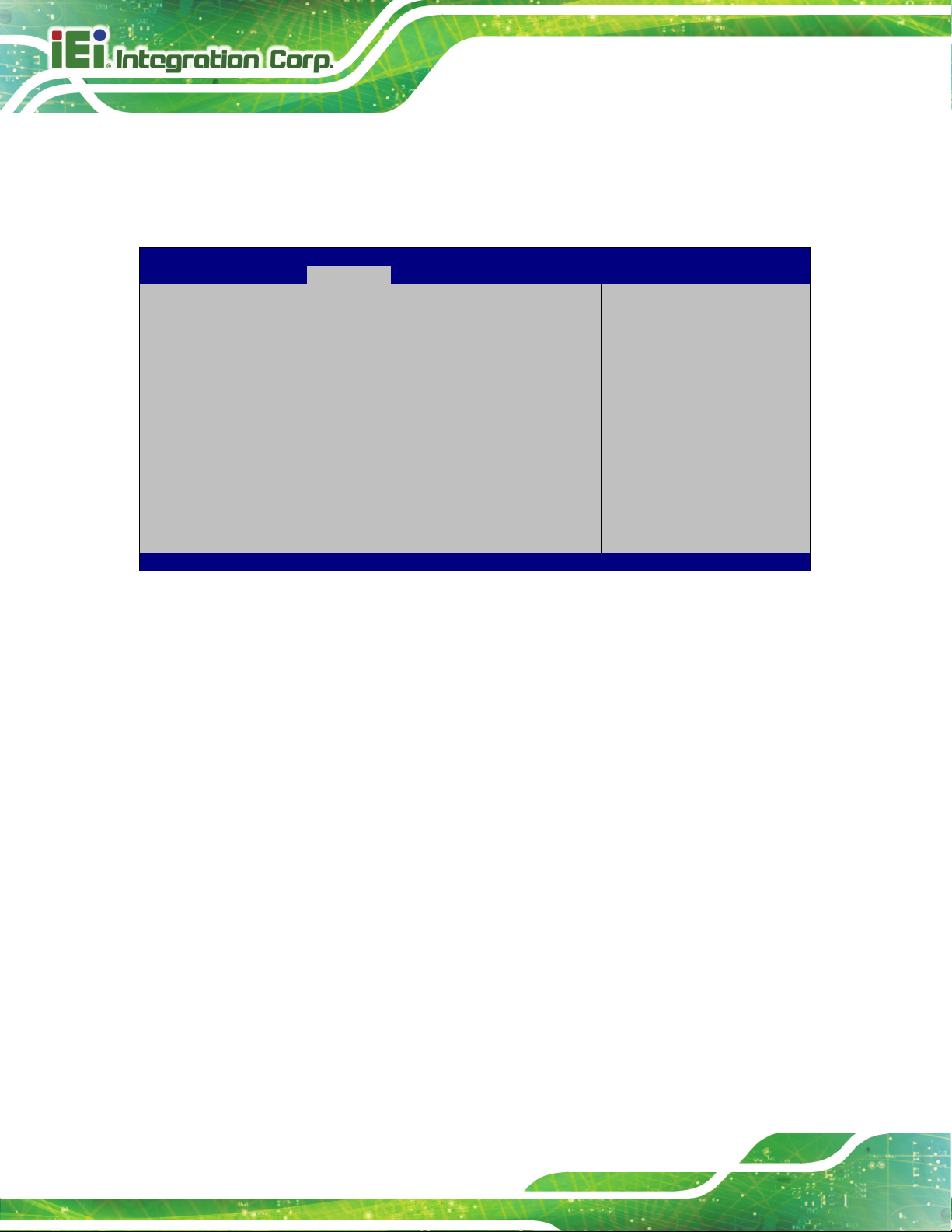
AFL3-W10A/12A/W15A-AL Panel PC
Page 82
Aptio Setup Utility – Copyright (C) 2019 American Megatrends, Inc.
Chipset
Version 2.18.1263. Copyright (C) 2019 American Megatrends, Inc.
4.4.2.2 PCI Express Configuration
Use the PCI Express Configuration menu (BIOS Menu 20) to configure the PCI
Express.
PCI Express Configuration
> M2_AKEY1
BIOS Menu 20: PCI Express Configuration
Compliance Mode
Enable/Disable
---------------------
: Select Screen
↑ ↓: Select Item
Enter Select
F1 General Help
F2 Previous Values
F3 Optimized
Defaults
F4 Save
ESC Exit
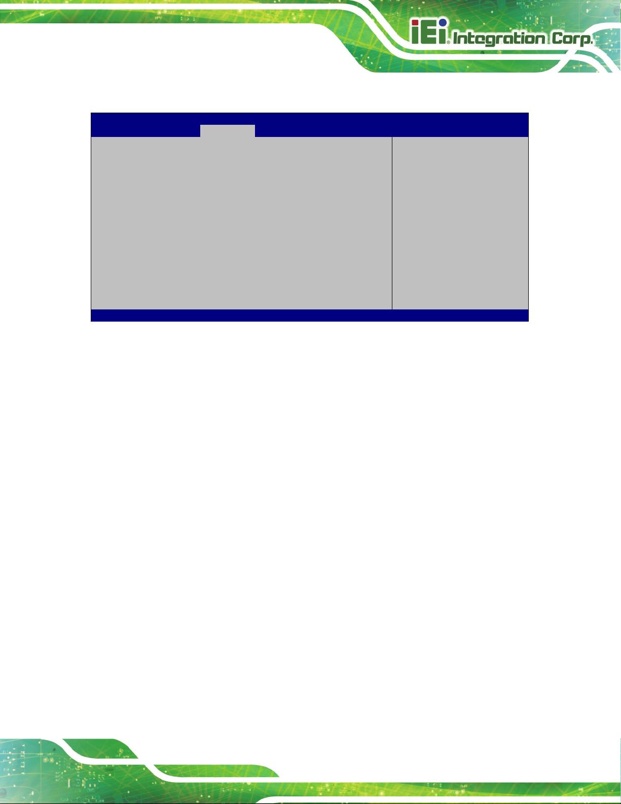
AFL3-W10A/12A/W15A-AL Panel PC
Page 83
Aptio Setup Utility – Copyright (C) 2019 American Megatrends, Inc.
Chipset
PCI Express port
Version 2.18.1263. Copyright (C) 2019 American Megatrends, Inc.
4.4.2.2.1 M2_AKEY1
PCIe Speed [Auto]
BIOS Menu 21: M2_AKEY1
PCIe Speed [Auto]
Use this option to select the support type of the PCI Express slot. The following options
are available:
Auto Default
Select
speed.
---------------------
: Select Screen
↑ ↓: Select Item
Enter: Select
+/-: Change Opt.
F1: General Help
F2: Previous Values
F3: Optimized Defaults
F4: Save & Exit
ESC: Exit
Gen1
Gen2
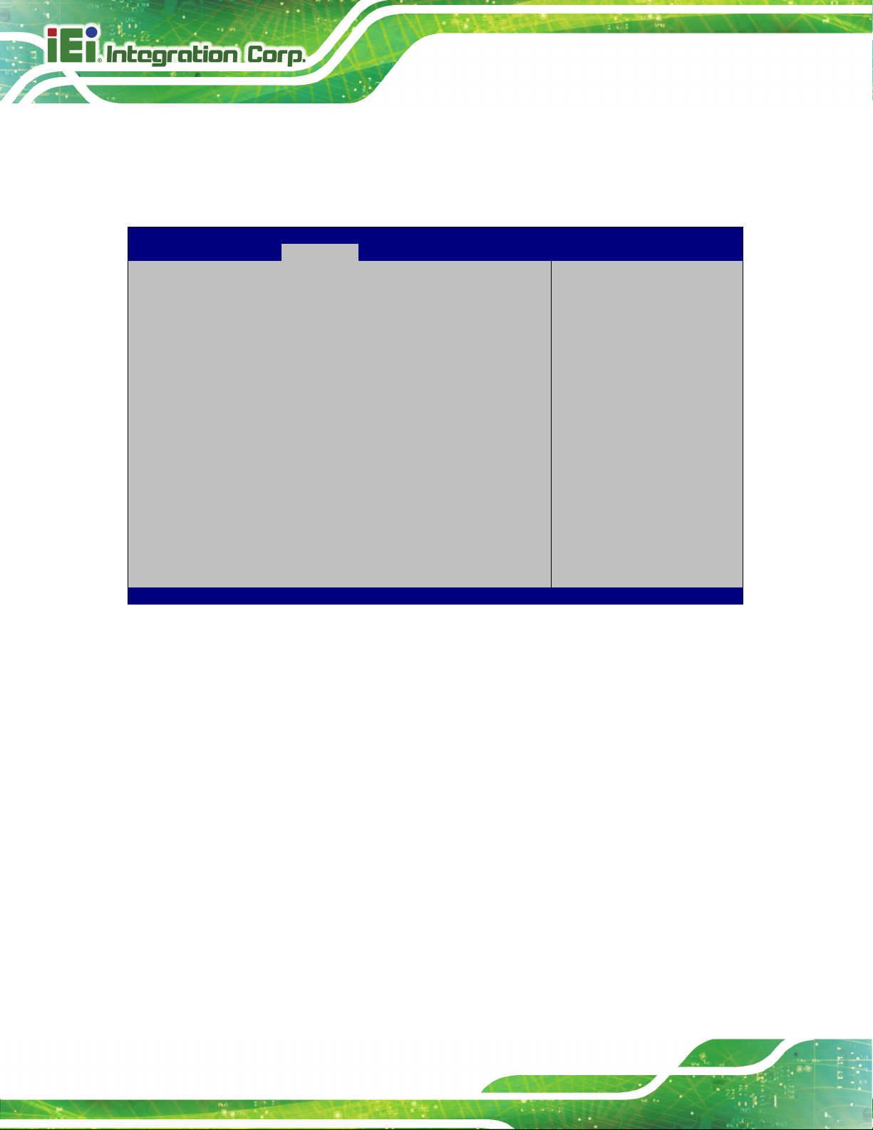
AFL3-W10A/12A/W15A-AL Panel PC
Page 84
Aptio Setup Utility – Copyright (C) 2019 American Megatrends, Inc.
Chipset
Enables or Disables the
controller supports the
ESC Exit
Version 2.18.1263. Copyright (C) 2019 American Megatrends, Inc.
4.4.2.3 SATA Configuration
Use the SATA Configuration menu (BIOS Menu 22) to change and/or set the
configuration of the SATA devices installed in the system.
SATA Configuration
STAT Controller [Enable]
SATA Mode Selection [AHCI]
SATA1 Empty
M2_1 Empty
Chipset SATA Controller.
The Chipset SATA
2 black internal SATA
ports (up to 3Gb/s
supported per port).
---------------------
: Select Screen
↑ ↓: Select Item
Enter Select
F1 General Help
F2 Previous Values
F3 Optimized
Defaults
F4 Save
STAT Controller [Enable]
Use the STAT Controller(s) option to enable or disable the SATA device.
SATA Mode Selection [AHCI]
Use the SATA Mode Selection option to configure SATA devices as AHCI devices.
BIOS Menu 22: SATA Configuration
Enable DEFAULT
Disable
AHCI DEFAU LT
Enables the SATA device.
Disables the SATA device.
Configures SATA devices as AHCI device.
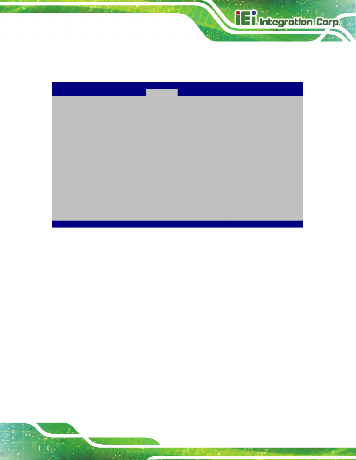
AFL3-W10A/12A/W15A-AL Panel PC
Page 85
Aptio Setup Utility – Copyright (C) 2019 American Megatrends, Inc.
Main
Advanced
Chipset
Security
Boot
Save & Exit
Version 2.18.1263. Copyright (C) 2019 American Megatrends, Inc.
4.5 Security
Use the Security menu (BIOS Menu 23) to set system and user passwords.
Password Description
If ONLY the Administrator’s password is set,
then this only limits access to Setup and is
only asked for when entering Setup.
If ONLY the User’s password is set, then this
is a power on password and must be entered to
boot or enter Setup. In Setup the User will
have Administrator rights.
The password must be
In the following range:
Maximum length 3
Minimum length 20
Administrator Password
User Password
BIOS Menu 23: Security
Administrator Password
Use the Administrator Password field to set or change an administrator password.
Set Administrator
Password
---------------------
: Select Screen
↑ ↓: Select Item
Enter Select
+/-: Change Opt.
F1: General Help
F2: Previous Values
F3: Optimized Defaults
F4: Save & Exit
ESC: Exit
User Password
Use the User Password field to set or change a user password.
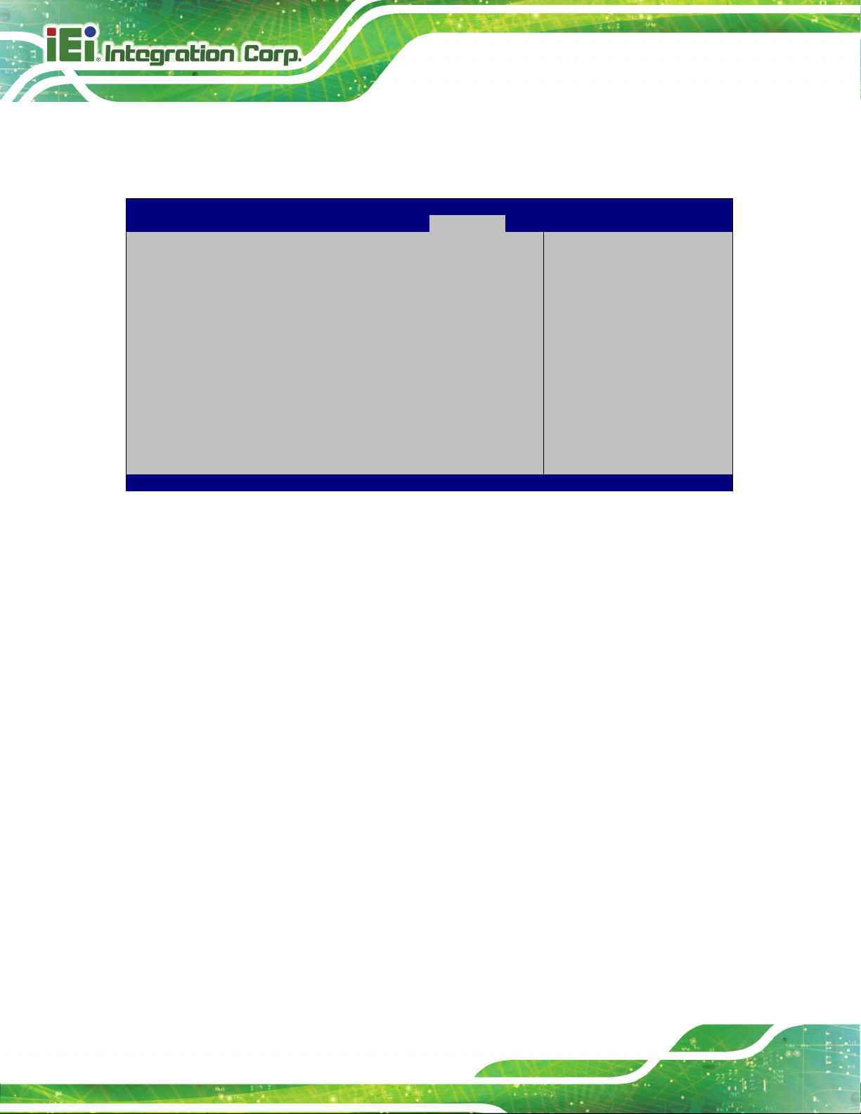
AFL3-W10A/12A/W15A-AL Panel PC
Page 86
Aptio Setup Utility – Copyright (C) 2019 American Megatrends, Inc.
Main
Advanced
Chipset
Security
Boot
Save & Exit
ESC: Exit
Version 2.18.1263. Copyright (C) 2019 American Megatrends, Inc.
Allows the Number Lock on the keyboard to be
enabled automatically when the computer system
boots up. This allows the immediate use of the
the keyboard. To confirm this, the Number Lock LED
Does not enable the keyboard Number Lock
e upper
key pad. The Number
Lock LED on the keyboard lights up when the
4.6 Boot
Use the Boot menu (BIOS Menu 24) to configure system boot options.
Boot Configuration
Bootup NumLock State [On]
Quiet Boot [Enabled]
Launch PXE OpROM [Disabled]
Option ROM Messages [Force BIOS]
UEFI Boot [Disabled]
Boot Option Priorities
BIOS Menu 24: Boot
Bootup NumLock State [On]
Use the Bootup NumLock State BIOS option to specify if the number lock setting must
be modified during boot up.
Select the keyboard
NumLock state
---------------------
: Select Screen
↑ ↓: Select Item
Enter Select
+/-: Change Opt.
F1: General Help
F2: Previous Values
F3: Optimized Defaults
F4: Save & Exit
On DEFAULT
Off
10-key numeric keypad located on the right side of
light on the keyboard is lit.
automatically. To use the 10-keys on the keyboard,
press the Number Lock key located on th
left-hand corner of the 10-
Number Lock is engaged.
 Loading...