

Page 1

AFOLUX Kiosk Application Series
Page i
Page 2

AFOLUX Kiosk Application Series
Revision
Date Version Changes
2008-04 1.00
Initial release
Page ii
Page 3

AFOLUX Kiosk Application Series
COPYRIGHT NOTICE
The information in this document is subject to change without prior notice in order to
improve reliability, design and function and does not represent a commitment on the part
of the manufacturer.
In no event will the manufacturer be liable for direct, indirect, special, incidental, or
consequential damages arising out of the use or inability to use the product or
documentation, even if advised of the possibility of such damages.
Copyright
This document contains proprietary information protected by copyright. All rights are
reserved. No part of this manual may be reproduced by any mechanical, electronic, or
other means in any form without prior written permission of the manufacturer.
TRADEMARKS
All registered trademarks and product names mentioned herein are used for identification
purposes only and may be trademarks and/or registered trademarks of their respective
owners.
Page iii
Page 4

AFOLUX Kiosk Application Series
Manual Conventions
WARNING!
Warnings appear where overlooked details may cause damage to the equipment or result
in personal injury. Warnings should be taken seriously. Warnings are easy to recognize.
The word “warning” is written as “WARNING,” both capitalized and bold and is followed by
text. The text is the warning message. A warning message is shown below:
WARNING:
This is an example of a warning message. Failure to adhere to warning
messages may result in permanent damage to the AFOLUX AFL-315
series or personal injury to the user. Please take warning messages
seriously.
CAUTION!
Cautionary messages should also be heeded to help reduce the chance of losing data or
damaging the AFOLUX AFL-315 series. Cautions are easy to recognize. The word
“caution” is written as “CAUTION,” both capitalized and bold and is followed. The italicized
text is the cautionary message. A caution message is shown below:
Page iv
Page 5

AFOLUX Kiosk Application Series
CAUTION:
This is an example of a caution message. Failure to adhere to cautions
messages may result in permanent damage to the AFOLUX AFL-315
series. Please take caution messages seriously.
NOTE:
These messages inform the reader of essential but non-critical information. These
messages should be read carefully as any directions or instructions contained therein can
help avoid making mistakes. Notes are easy to recognize. The word “note” is written as
“NOTE,” both capitalized and bold and is followed by text. The text is the cautionary
message. A note message is shown below:
NOTE:
This is an example of a note message. Notes should always be read.
Notes contain critical information about the AFOLUX AFL-315 series.
Please take note messages seriously.
Page v
Page 6

AFOLUX Kiosk Application Series
Packing List
NOTE:
If any of the components listed in the checklist below are missing,
please do not proceed with the installation. Contact the IEI reseller or
vendor you purchased the AFOLUX AFL-315 series from or contact an
IEI sales representative directly. To contact an IEI sales representative,
please send an email to
The items listed below should all be included in the AFOLUX AFL-315 series package.
1 x Power cord
1 x Power adapter
1 x Touch pen
1 x User Manual and driver CD
1 x Panel mounting kit (optional)
1 x Wall mounting kit (optional)
1 x 128MB CompactFlash® card with Windows CE 5.0 pre-installed (optional)
1 x 1GB CompactFlash® card with Windows XPE pre-installed (optional)
Images of the above items are shown in Chapter 3 on page
sales@iei.com.tw.
34.
Page vi
Page 7

AFOLUX Kiosk Application Series
Table of Contents
1 INTRODUCTION..................................................................................................... 1
1.1 AFOLUX AFL-315AB/W SERIES FLAT PANEL PC OVERVIEW................................. 2
1.1.1 Features and Model Variations.......................................................................... 3
1.1.2 Applications ....................................................................................................... 3
1.1.3 Standard Features.............................................................................................. 3
1.2 EXTERNAL OVERVIEW ............................................................................................... 4
1.2.1 General Description........................................................................................... 4
1.2.2 Front Panel........................................................................................................ 4
1.2.3 Rear Panel ......................................................................................................... 5
1.2.4 I/O Interface Panel ............................................................................................ 6
1.2.5 Top Panel and Bottom Panel.............................................................................. 7
1.2.6 Rear Panel Connectors...................................................................................... 8
1.3 INTERNAL OVERVIEW................................................................................................. 8
1.4 SPECIFICATIONS ......................................................................................................... 9
1.4.1 Preinstalled Hardware Components.................................................................. 9
1.4.2 System Specifications......................................................................................... 9
2 DETAILED SPECIFICATIONS........................................................................... 13
2.1 DIMENSIONS ............................................................................................................ 14
2.1.1 Front Panel Dimensions.................................................................................. 14
2.1.2 Side Dimensions............................................................................................... 14
2.1.3 Top and Bottom Panel Dimensions.................................................................. 15
2.2 INTEL® DESK-TOP PROCESSOR SUPPORT ................................................................ 16
2.3 MOTHERBOARD COMPONENTS................................................................................. 17
2.3.1 Memory Support............................................................................................... 17
2.3.1.1 Installed Memory...................................................................................... 17
2.3.1.2 Additional Memory................................................................................... 17
2.3.2 Storage Capacity.............................................................................................. 18
2.4 EXTERNAL PERIPHERAL INTERFACE CONNECTORS .................................................. 18
2.4.1 Serial Port Connectors .................................................................................... 18
2.4.2 LAN Connectivity............................................................................................. 19
Page vii
Page 8

2.4.3 External USB Connectors................................................................................ 20
2.4.4 Keyboard and Mouse Connectivity.................................................................. 20
2.5 AFOLUX AFL-315 FRONT SIDE............................................................................. 21
2.5.1 Monitor ............................................................................................................ 21
2.5.2 Touch-Screen Module....................................................................................... 22
2.6 GRAPHICS ................................................................................................................ 22
2.6.1 Intel® 945G Integrated Graphics Media Accelerator 950............................... 22
2.6.2 DVI Graphics................................................................................................... 23
2.6.3 Dual-Display.................................................................................................... 24
2.7 AUDIO...................................................................................................................... 24
2.7.1 Audio Codec ’97 Controller............................................................................. 24
2.7.2 Stereo Speakers ................................................................................................ 24
2.8 SYSTEM POWER ....................................................................................................... 25
2.8.1 Power Mode..................................................................................................... 25
AFOLUX Kiosk Application Series
2.8.1.1 AT Power Mode ........................................................................................ 25
2.8.1.2 ATX Power Mode ..................................................................................... 26
2.8.2 Power Supply................................................................................................... 26
2.8.3 Power Connectors............................................................................................ 26
2.8.3.1 Power Input Connector............................................................................. 27
2.8.3.2 Power Output Connector........................................................................... 27
2.8.4 RJ-12 Connector for Cash Draw Power.......................................................... 27
2.9 WIRELESS CONNECTIONS......................................................................................... 28
2.9.1 USB Bluetooth Module .................................................................................... 28
2.9.2 Wireless Ethernet ............................................................................................. 29
2.10 OPTIONAL MODULES ............................................................................................. 30
2.10.1 GPRS Module (Optional)............................................................................... 30
2.11 SYSTEM VENTILATION ........................................................................................... 30
3 UNPACKING .......................................................................................................... 33
3.1 UNPACKING.............................................................................................................. 34
3.1.1 Packing List ..................................................................................................... 34
4 INSTALLATION .................................................................................................... 37
4.1 ANTI-STATIC PRECAUTIONS...................................................................................... 38
4.2 INSTALLATION PRECAUTIONS................................................................................... 38
Page viii
Page 9

AFOLUX Kiosk Application Series
4.3 PREINSTALLED COMPONENTS .................................................................................. 39
4.4 INST ALLATION AND CONFIGURATION STEPS............................................................. 39
4.5 REMOVING THE BACK PANEL................................................................................... 40
4.6 CF CARD INSTALLATION.......................................................................................... 41
4.7 JUMPER SETTINGS.................................................................................................... 42
4.7.1 Access the Jumpers.......................................................................................... 43
4.7.2 Preconfigured Jumpers .................................................................................... 43
4.7.3 Clear CMOS Jumper........................................................................................ 44
4.7.4 COM1 to COM6 Pin 9 Select........................................................................... 45
4.7.5 COM6 RX Function Select Jumper.................................................................. 46
4.7.6 COM6 TX Function Select Jumper.................................................................. 47
4.7.7 COM6 RS-232/422/485 Serial Port Select Jumper ......................................... 49
4.8 AT/ATX MODE SELECTION ..................................................................................... 50
4.9 MOUNTING THE SYSTEM.......................................................................................... 52
4.9.1 Wall Mounting.................................................................................................. 53
4.9.2 Panel Mounting................................................................................................ 55
4.9.3 Arm Mounting .................................................................................................. 57
4.9.4 Cabinet and Rack Installation ......................................................................... 58
4.10 BOTTOM PANEL CONNECTORS ............................................................................... 60
4.10.1 LAN Connection............................................................................................. 60
4.10.2 Serial Device Connection .............................................................................. 61
4.10.3 USB Device Connection................................................................................. 63
4.11 WEBCAM DRIVER INSTALLATION ........................................................................... 64
5 SYSTEM MAINTENANCE .................................................................................. 71
5.1 SYSTEM MAINTENANCE INTRODUCTION.................................................................. 72
5.2 ANTI-STATIC PRECAUTIONS...................................................................................... 72
5.3 TURN OFF THE POWER.............................................................................................. 73
5.4 OPENING THE SYSTEM ............................................................................................. 73
5.4.1 Removing the Back Panel ................................................................................ 73
5.4.2 Removing the Plastic Cover............................................................................. 75
5.4.3 Removing the Metal Cover............................................................................... 75
5.4.4 Removing the Processor and DIMM Housing................................................. 78
5.5 REPLACING COMPONENTS ....................................................................................... 79
5.5.1 Hard Disk Drive Replacement......................................................................... 79
Page ix
Page 10

5.5.2 CF Card Replacement...................................................................................... 80
5.5.3 DIMM Module Replacement............................................................................ 82
5.5.4 CPU Replacement............................................................................................ 84
5.5.5 Cooling Fan Replacement................................................................................ 88
5.6 REINST ALLING THE COVERS..................................................................................... 90
6 AMI BIOS SETUP.................................................................................................. 91
6.1 INTRODUCTION ........................................................................................................ 92
6.1.1 Starting Setup................................................................................................... 92
6.1.2 Using Setup...................................................................................................... 92
6.1.3 Getting Help..................................................................................................... 93
6.1.4 Unable to Reboot After Configuration Changes.............................................. 93
6.1.5 BIOS Menu Bar................................................................................................ 93
6.2 MAIN ....................................................................................................................... 94
6.3 ADVANCED............................................................................................................... 95
AFOLUX Kiosk Application Series
6.3.1 CPU Configuration.......................................................................................... 96
6.3.2 IDE Configuration........................................................................................... 98
6.3.2.1 IDE Master, IDE Slave........................................................................... 100
6.3.3 Super IO Configuration.................................................................................. 105
6.3.4 Hardware Health Configuration.....................................................................111
6.3.5 Power Configuration ......................................................................................117
6.3.6 ACPI Configuration ........................................................................................117
6.3.7 APM Configuration.........................................................................................119
6.3.8 Remote Access Configuration........................................................................ 121
6.3.9 USB Configuration......................................................................................... 125
6.4 PCI/PNP ................................................................................................................ 127
6.5 BOOT ..................................................................................................................... 130
6.5.1 Boot Settings Configuration........................................................................... 130
6.5.2 Boot Device Priority...................................................................................... 133
6.6 SECURITY............................................................................................................... 134
6.7 CHIPSET ................................................................................................................. 135
6.7.1 NorthBridge Chipset Configuration .............................................................. 136
6.7.2 SouthBridge Configuration............................................................................ 139
6.8 EXIT....................................................................................................................... 140
7 SYSTEM MONITORING.................................................................................... 143
Page x
Page 11

AFOLUX Kiosk Application Series
7.1 IEI INTELLIGENT SYSTEM MANAGEMENT MODULE (ISMM)................................. 144
7.1.1 What is iSMM................................................................................................. 144
7.1.2 iSMM Features............................................................................................... 144
7.2 COM PORT LED INDICATORS ................................................................................ 145
A SYSTEM SPECIFICATIONS ............................................................................. 147
A.1 MOTHERBOARD SPECIFICATIONS .......................................................................... 148
A.2 PROCESSOR SPECIFICATIONS ................................................................................. 149
A.3 SCREEN SPECIFICATIONS ....................................................................................... 149
A.4 TOUCH SCREEN SPECIFICATIONS........................................................................... 150
POWER SUPPLY MODULE ............................................................................................. 151
A.5 WEBCAM SPECIFICATIONS..................................................................................... 152
A.6 BLUETOOTH MODULE SPECIFICATIONS ................................................................. 152
A.7 COOLING FAN SPECIFICATIONS.............................................................................. 153
A.8 OPTIONAL GPRS MODULE SPECIFICATIONS ......................................................... 153
B EXTERNAL CONNECTOR PINOUTS............................................................. 155
B.1 INTRODUCTION...................................................................................................... 156
B.2 DVI CONNECTOR.................................................................................................. 156
B.3 KEYBOARD/MOUSE CONNECTOR .......................................................................... 156
B.4 LAN CONNECTORS............................................................................................... 157
B.5 RJ-12 CASH DRAWER CONNECTOR....................................................................... 157
B.6 SERIAL PORT CONNECTORS................................................................................... 158
B.7 USB CONNECTOR ................................................................................................. 158
B.8 VGA CONNECTOR................................................................................................. 158
C SAFETY PRECAUTIONS................................................................................... 161
C.1 SAFETY PRECAUTIONS........................................................................................... 162
C.1.1 General Safety Precautions........................................................................... 162
C.1.2 Anti-static Precautions.................................................................................. 163
C.2 MAINTENANCE AND CLEANING PRECAUTIONS...................................................... 163
C.2.1 Maintenance and Cleaning ........................................................................... 163
C.2.2 Cleaning Tools............................................................................................... 164
D BIOS CONFIGURATION OPTIONS ................................................................ 167
D.1 BIOS CONFIGURATION OPTIONS........................................................................... 168
Page xi
Page 12

E WATCHDOG TIME R.......................................................................................... 171
F HAZARDOUS MATERIALS DISCLOSURE................................................... 175
F.1 HAZARDOUS MATERIAL DISCLOSURE TABLE FOR IPB PRODUCTS CERTIFIED AS
ROHS COMPLIANT UNDER 2002/95/EC WITHOUT MERCURY..................................... 176
INDEX............................................................................................................................ 179
AFOLUX Kiosk Application Series
Page xii
Page 13

AFOLUX Kiosk Application Series
Figure 1-1: AFOLUX AFL-315A W.................................................................................2
Figure 1-2: AFL-315 Front Vie w ...................................................................................5
Figure 1-3: AFL-315 Rear View.....................................................................................6
Figure 1-4: AFL-315 I/O Interface Connector Panel...................................................7
Figure 1-5: AFL-315 Top View ......................................................................................7
Figure 1-6: AFL-315 Bottom View ................................................................................7
Figure 1-7: AFL-315 Side Views...................................................................................8
Figure 2-1: AFL-315 Front Panel Dimensions (mm).................................................14
Figure 2-2: AFL-315 Side Panel Dimensions (mm...................................................15
List of Figures
Figure 2-3: AFL-315 Top and Bottom Panel Dimensions (mm) ..............................15
Figure 2-4: Processor .................................................................................................16
Figure 2-5: Memory Module and Memory Socket....................................................17
Figure 2-6: COM Ports and LED Indicators...............................................................18
Figure 2-7: RJ-45 Ethernet Connector ......................................................................19
Figure 2-8: External USB Ports..................................................................................20
Figure 2-9: Keyboard and Mouse Connector ...........................................................21
Figure 2-10: XGA Screen............................................................................................22
Figure 2-11: VGA Connector ......................................................................................23
Figure 2-12: DVI Connector........................................................................................23
Figure 2-13: Audio Codec and Audio Jacks .............................................................24
Figure 2-14: Stereo Speakers.....................................................................................25
Figure 2-15: Power Supply Unit.................................................................................26
Figure 2-16: Power Connectors.................................................................................27
Figure 2-17: RJ-12 Connector....................................................................................28
Figure 2-18: Bluetooth Module ..................................................................................29
Figure 2-19: PIFA Antenna..........................................................................................30
Figure 2-20: Internal View of Cooling Fans ..............................................................31
Figure 2-21: Cooling Fan Dimensions.......................................................................31
Page xiii
Page 14

Figure 4-1: Rear Panel Retention Screws.................................................................40
Figure 4-2: HDD Bracket Retention Screws .............................................................41
Figure 4-3: CF Card Insert..........................................................................................42
Figure 4-4: Jumper Locations....................................................................................42
Figure 4-5: Clear CMOS Jumper................................................................................45
Figure 4-6: COM1, COM4, COM5 and COM6 Pin 9 Setting Jumper Location........46
Figure 4-7: COM6 RX Function Select Jumper Location ........................................47
Figure 4-8: COM6 TX Function Select Jumper Pinout Locations ..........................48
Figure 4-9: COM6 RS-232/422/485 Serial Port Select Jumper Location................50
Figure 4-10: Back Cover Retention Screws..............................................................51
Figure 4-11: AT/ATX Switch........................................................................................52
Figure 4-12: Wall-mounting Bracket..........................................................................53
Figure 4-13: Chassis Support Screws.......................................................................54
AFOLUX Kiosk Application Series
Figure 4-14: Secure the Panel PC..............................................................................55
Figure 4-15: AFL-315 Panel Opening ........................................................................56
Figure 4-16: Tighten the Panel Mounting Clamp Screws........................................56
Figure 4-17: AFL-315 Arm Mounting Retention Screw Holes.................................58
Figure 4-18: The Rack/Cabinet Bracket ....................................................................59
Figure 4-19: Secure the Rack/Cabinet Bracket........................................................59
Figure 4-20: Install into a Rack/Cabinet....................................................................60
Figure 4-21: LAN Connection.....................................................................................61
Figure 4-22: Serial Device Connector .......................................................................62
Figure 4-23: USB Device Connection........................................................................63
Figure 4-24: Preparing for Driver Installation...........................................................64
Figure 4-25: Driver Installation Starting Screen.......................................................65
Figure 4-26: Ready to Install Driver...........................................................................66
Figure 4-27: Driver Installs.........................................................................................67
Figure 4-28: Confirm Digital Signature .....................................................................68
Page xiv
Figure 4-29: Installation Complete ............................................................................69
Figure 4-30: Restart the computer.............................................................................70
Figure 5-1: Rear Panel Retention Screws (Back).....................................................74
Figure 5-2: Rear Panel Retention Screws (Bottom).................................................74
Page 15

AFOLUX Kiosk Application Series
Figure 5-3: Back Cover Retention Screws................................................................75
Figure 5-4: Metal Enclosure Retention Screws........................................................76
Figure 5-5: Peripheral Interface Connector Screwdrivers ......................................77
Figure 5-6: Peripheral Connector Retention Screws...............................................77
Figure 5-7: Processor and DIMM Housing................................................................78
Figure 5-8: HDD Bracket Retention Screws .............................................................79
Figure 5-9: HDD Retention Screws............................................................................80
Figure 5-10: Locate the CF Card................................................................................81
Figure 5-11: DIMM Socket Location...........................................................................83
Figure 5-12: Installing a DIMM....................................................................................84
Figure 5-13: Heat Sink Retention Screws.................................................................85
Figure 5-14: Processor ...............................................................................................86
Figure 5-15: Open the CPU Socket Load Plate ........................................................86
Figure 5-16: Insert the Socket LGA775 CPU ............................................................87
Figure 5-17: Fan Retention Screws...........................................................................89
Figure 5-18: Fan Cable Connectors...........................................................................89
Figure 7-1: iSMM....................................................................................................... 144
Page xv
Page 16

AFOLUX Kiosk Application Series
List of Tables
Table 1-1: AFL-315 Series System Specifications ...................................................11
Table 4-1: Jumpers......................................................................................................43
Table 4-2: Preconfigured Jumpers............................................................................44
Table 4-3: Clear CMOS Jumper Settings...................................................................45
Table 4-4: COM1, COM4, COM5 and COM6 Pin 9 Setting Jumper Settings ..........46
Table 4-5: COM6 RX Function Select Jumper Settings ...........................................47
Table 4-6: COM6 TX Function Select Jumper Settings ...........................................48
Table 4-7: COM6 RS-232/422/485 Serial Port Select Jumper Settings...................49
Table 6-1: BIOS Navigation Keys...............................................................................93
Table 7-1: Bluetooth Module Specifications.......................................................... 153
Page xvi
Page 17

AFOLUX Kiosk Application Series
Chapter
1
1 Introduction
Page 1
Page 18

AFOLUX Kiosk Application Series
1.1 AFOLUX AFL-315AB/W Series Flat Panel PC Overview
Figure 1-1: AFOLUX AFL-315AW
The AFOLUX315AB and AFOLUX315W (AFL-315) are Intel® Core™2 Duo or Intel®
Celeron® D powered flat panel PCs with a rich variety of functions and peripherals. Both
AFL-315 models are designed for easy and simplified integration in to kiosk and
point-of-sales (POS) applications.
An Intel® 945G graphics memory controller hub (GMCH) coupled with an Intel® ICH7
input/output controller hub ensures optimal memory, graphics, and peripheral I/O support.
The system comes with 1.0 GB of preinstalled DDR2 SDRAM and supports a maximum of
4.0 GB of DDR2 SDRAM ensuring smooth data throughputs with reduced bottlenecks and
fast system access.
Four serial ports and eight external USB 2.0 ports ensure simplified connectivity to a
variety of external peripheral devices. A VGA and DVI-I connector enable connectivity to
Page 2
other monitors. Wi-Fi capabilities and an RJ-45 Ethernet connector ensure smooth
connection of the system to an external LAN.
Page 19

AFOLUX Kiosk Application Series
A white or black AFL-315 is available to ensure the AFL-315 system blends into its
operational environment.
1.1.1 Features and Model Variations
There are two models in the AFL-315 series, the AFL-315AB-945/WT-R/1G and the
AFL-315AW-945/WT-R/1G. Both models feature the following:
Intel® Core™2 Duo processor
15" XGA panel PC
Intel® 945G chipset
1GB DDR2 SDRAM preinstalled
802.11 b/g wireless module
Touch screen
Bluetooth
WebCAM
RoHS comlpliance
There is both a black AFL-315 model and a white AFL-315 model. The model numbers
are listed below.
AFL-315AB-945/WT-R/1G Black
AFL-315AW-945/WT-R/1G White
1.1.2 Applications
The AFL-315 panel PCs are elegant yet sophisticated systems that are easily
implemented in commercial environments, industrial environments and corporate
environments.
1.1.3 Standard Features
Some of the standard features of the AFOLUX AFL-315 series flat panel PC include:
Built-in 2.0 mega pixel webcam with auto focus function
Four standard RS-232 connectors with user configured pin 9 signals being set
as RI, +5.0 V or +12.0 V
Page 3
Page 20

Eight USB 2.0 ports
Watchdog timer that triggers a system reset if the system hangs for some
reason
iSMM system health supervision API to track the system status
Built-in stereo speakers
Bluetooth functionality
Touch screen option
Wireless LAN connectivity
IP 64 compliant front panel
AT or ATX power mode
RoHS compliant
1.2 External Overview
1.2.1 General Description
AFOLUX Kiosk Application Series
The stylish AFL-315 panel PC comprises of a screen, rear panel, top panel, bottom panel
and two side panels (left and right). An ABS/PC plastic front frame surrounds the front
screen. The rear panel provides screw holes for a wall-mounting bracket compliant with
VESA FDMI standard. An I/O interface panel on the rear panel of the AFL-315 provides
access to external interface connectors that include LAN, USB 2.0, serial port, reset
button, power connector and power switch.
1.2.2 Front Panel
The front side of the AFOLUX AFL-315 series is a flat panel TFT LCD screen surrounded
by an ABS/PC plastic frame. The top of the front panel has an auto focus 2.0 MP camera
and the bottom of the front panel features two speakers for stereo sound.
Page 4
Page 21

AFOLUX Kiosk Application Series
Figure 1-2: AFL-315 Front View
1.2.3 Rear Panel
The rear panel provides access to retention screw holes that support the wall mounting
and to the I/O interface panel that enable connection to a wide range of external peripheral
devices. Refer to
Figure 1-3.
Page 5
Page 22

AFOLUX Kiosk Application Series
Figure 1-3: AFL-315 Rear View
1.2.4 I/O Interface Panel
The I/O interface panel located on the rear side of the AFL-315 (see Figure 1-3 above)
has the following I/O interface connectors:
1 x 24 V DC Out connector
1 x 12 V or 24 V DC In connector
8 x USB 2.0 connectors
1 x LAN connector
1 x RJ-12 connector
3 x RS-232 connectors
1 x RS-232/422/485 connector
1 x PS/2 connector
1 x Line out audio jack
1 x Line in audio jack
Page 6
1 x Mic in audio jack
1 x DVI out connector
Page 23

AFOLUX Kiosk Application Series
The external I/O interface connector panel is shown in Figure 1-4.
Figure 1-4: AFL-315 I/O Interface Connector Panel
1.2.5 Top Panel and Bottom Panel
The top panel and side panels of AFOLUX AFL-315 series provides access to slots that
support panel mount and rack mount (
Figure 1-5: AFL-315 Top View
Figure 1-5 and Figure 1-6).
Figure 1-6: AFL-315 Bottom View
Page 7
Page 24
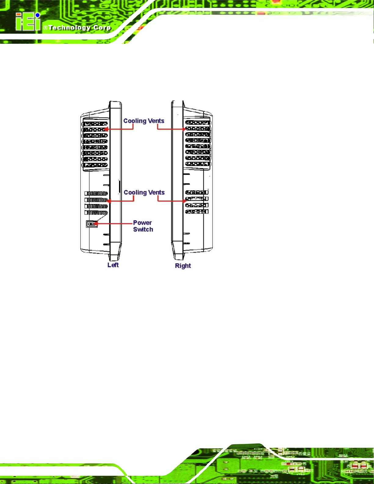
1.2.6 Rear Panel Connectors
The side panels of the AFL-315 panel PC have ventilation vents that cool the interior of the
AFOLUX Kiosk Application Series
system. The left panel also has a power switch near the bottom. See
Figure 1-7.
Figure 1-7: AFL-315 Side Views
1.3 Internal Overview
The AFOLUX AFL-315 has the following components installed internally:
1 x Motherboard
1 x 1.0 GB DDR2 SDRAM DIMM
1 x 160 GB SATA HDD
1 x Wireless module
1 x Bluetooth module
1 x CF Type II card (user installed)
Page 8
Page 25

AFOLUX Kiosk Application Series
1.4 Specifications
1.4.1 Preinstalled Hardware Components
The AFOLUX AFL-315 series flat panel PC has the following preinstalled components:
1 x Motherboard
1 x TFT LCD screen
1 x Touch screen
1 x Inverter
1 x Wireless LAN module
1 x DDR memory module
1 x Bluetooth module
1 x AT/ATX switch
1 x GPRS module (optional)
The technical specifications for some of these components and the system are shown in
the sections below.
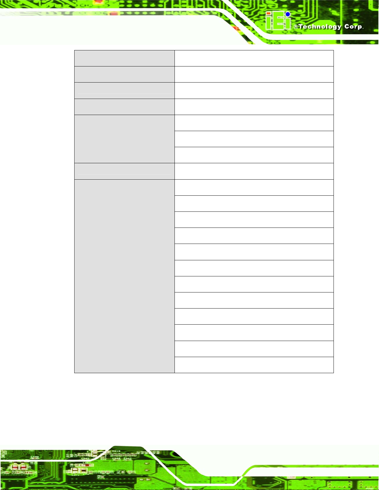
1.4.2 System Specifications
The technical specifications for the AFOLUX AFL-315 series systems are listed in Table
1-1.
Specification
LCD Size
Contrast Ratio
LCD Color
Pixel Pitch (mm)
Viewing Angle (H-V)
Backlight MTBF
Parameters
15”
700:1
262K
0.297 (H) x 0.297 (V)
140 (H) / 0.297 (V)
50,000 hours
SBC Model
AFLMB-9454 Rev. 1.0
Page 9
Page 26

AFOLUX Kiosk Application Series
CPU
Graphics Memory Controller
Hub
Memory
Brightness (cd/m2)
SSD
Watchdog Timer
Audio
Camera
Expansion
1.8 GHz Intel® Dual Core desktop (E2160) or others
Intel® 945G
One 1.0 GB DDR2 SDRAM DIMM pre-installed
350
CF Type II
Software Programmable supports 1 sec. ~ 255 sec.
system reset
AMP 1.5 W + AMP 1.5 W (built-in stereo speakers)
2 Mega pixel with auto focus
1 x PCIe mini card
1 x Mini PCI interface (wireless LAN 802.11 b/g module
HDD Drive Bay
Construction Material
Mounting
Front Panel Color
Dimensions (W x H x D) (mm)
Operation Temperature
Storage Temperature
1 x Bluetooth module (USB interface, Bluetooth v 2.0)
1 x 3.5” SATA HDD bay or
1 x 2.5” SATA HDD bay
ABS + PC plastic front frame
Panel
Wall
Stand
Arm (VESA 100 mm x 100 mm)
Black or White
363 x 322 x 80
0ºC ~ 45ºC
-20ºC ~ 80ºC
Page 10
Net weight
6.8 kg
Page 27
AFOLUX Kiosk Application Series
IP level (front panel)
EMC
Safety
Touch Screen
Power Adapter (ACE-D825AH)
Power Consumption
I/O Ports and Switches
IP 64
CE, FCC and CCC
UL and CB
Resistive Type 5-wire (touch controller IC is on board)
252 W
Input: 90 VAC ~ 264 VAC @ 50 Hz / 60 Hz
Output: 12 VDC at 15 A, 24 VDC at 3 A
102 W
1 x 12 V/ 24 V DC input jack
1 x PS/2 connector
3 x RS-232 COM port connectors
1 x RS-232/422/485 COM port connector
1 x RJ-12. 12 V/ 24 V cash draw port connector
1 x RJ-45 for GbE LAN
1 x Power switch
1 x Reset button
1 x DCI port
1 x VGA port
1 x Line-in, 1 x Line-out, 1 x Mic-in
1 x 24 V DC output jack
Table 1-1: AFL-315 Series System Specifications
Page 11
Page 28

AFOLUX Kiosk Application Series
THIS PAGE IS INTENTIONALLY LEFT BLANK
Page 12
Page 29

AFOLUX Kiosk Application Series
Chapter
2
2 Detailed Specifications
Page 13
Page 30

2.1 Dimensions
The following sections provide detailed schematics and information on the dimensions of
the AFL-315.
2.1.1 Front Panel Dimensions
Front panel dimensions are shown in Figure 2-1 and listed below.
Width: 364.4 mm
Height: 323.4 mm
AFOLUX Kiosk Application Series
Figure 2-1: AFL-315 Front Panel Dimensions (mm)
2.1.2 Side Dimensions
Side panel dimensions are shown in Figure 2-2 and listed below.
Screen Depth: 23.0 mm
AFL-315 Depth: 82.6 mm
Page 14
Page 31

AFOLUX Kiosk Application Series
Screen Protrusion (Top): 13.4 mm
Screen Protrusion (Bottom): 12.9 mm
Figure 2-2: AFL-315 Side Panel Dimensions (mm
2.1.3 Top and Bottom Panel Dimensions
Top and bottom panel dimensions are shown in Figure 2-3 and listed below.
Screen Protrusion (Right): 15.1 mm
Screen Protrusion (Left): 15.1 mm
Figure 2-3: AFL-315 Top and Bottom Panel Dimensions (mm)
Page 15
Page 32

AFOLUX Kiosk Application Series
2.2 Intel® Desk-Top Processor Support
An E2160 Intel® LGA775 Pentium® Dual-Core desktop processor is installed in the
system. The processor has a CPU speed of 1.8 GHz and an 800 MHz front side bus
(FSB). The processor also comes with a 1.0 MB L2 cache and a 1.8 GHz L2 cache speed.
The processor is shown in
Figure 2-4 below.
Page 16
Figure 2-4: Processor
E2160 Intel® LGA775 Pentium® Dual-Core desktop processor supports the following
Intel® features:
Dual Core
Enhanced Intel Speedstep® Technology
Intel® EM64T 1
Enhanced Halt State (C1E)
Execute Disable Bit 2
Intel® Thermal Monitor 2
Page 33

AFOLUX Kiosk Application Series
2.3 Motherboard Components
The following sections describe some of the features on the motherboard.
2.3.1 Memory Support
2.3.1.1 Installed Memory
One 240-pin 1.0 GB DDR2 SDRAM DIMM is installed in the AFL-315 and controlled by
the Intel® 945G GMCH installed on the internal motherboard.
2.3.1.2 Additional Memory
The Intel® 945G is capable of supporting two 240-pin 2.0 GB (max.) 667 MHz, 533 MHz
or 400 MHz DDR2 SDRAM DIMM (system max. 4.0 GB). If additional memory is required,
please contact an IEI sales representative and discuss the necessary system
requirement.
Figure 2-5: Memory Module and Memory Socket
Page 17
Page 34

AFOLUX Kiosk Application Series
2.3.2 Storage Capacity
The AFL-315 comes with a preinstalled 160 GB 150 Mbps SATA hard disk drive. The
system can also support an easily installed CompactFlash® Type II (CF Type II) memory
disk.
2.4 External Peripheral Interface Connectors
The following section describes the external peripheral interface connectors on the rear
panel of the subsystem.
2.4.1 Serial Port Connectors
The AFL-315 has four serial ports. Three of these ports (COM1, COM3 and COM4) are
RS-232 only ports. The COM2 serial port can be configured as a RS-232, RS-422 or an
RS-485 serial port. Pin 9 on all ports can be set as the normal ring (RI) signal or can be
designated as a 5 V or 12 V power supply. Pin 9 settings are shown with red, yellow and
green LED indicators next to the DB-9 CON port connectors on the rear panel. Enabling
COM devices to be powered through the COM port eliminates unnecessary and messy
cabling.
Page 18
Figure 2-6: COM Ports and LED Indicators
Page 35

AFOLUX Kiosk Application Series
Two of the serial ports (COM1 and COM2) are interfaced to the ITE IT8712 super, through
the low pin count (LPC) bus to the ICH7 Southbridge. The remaining two serial ports
(COM3 and COM4) are connected to the ICH7 LPC bus through a Fintek serial port
controller.
2.4.2 LAN Connectivity
One of the PCI Express (PCIe x1) lanes from the ICH7 Southbridge is interfaced to a
Broadcom BCM5797 PCIe gigabit Ethernet (GbE) controller. The BCM5797 is then
connected directly to the RJ-45 connector on the rear panel and provides external PCIe
GbE connectivity.
Figure 2-7: RJ-45 Ethernet Connector
The Broadcom BCM5787M PCIe GbE controller is a 10/100/1000BASE-T Ethernet LAN
controller. The BCM5787M combines a triple-speed IEEE 802.3 compliant Media Access
Controller (MAC) with a triple-speed Ethernet transceiver, a PCIe bus interface, and an
on-chip buffer memory. Some of the BCM5787 controller features are listed below:
Integrated 10/100/1000BASE-T transceiver
Page 19
Page 36

Automatic MDI crossover function
PCIe v1.0a
10/100/1000BASE-T full/half-duplex MAC
Wake on LAN support meeting the ACPI requirements
Statistics for SNMP MIB II, Ethernet-like MIB, and Ethernet MIB (802.3z,
clause 30)
Serial EEPROM or serial flash support
2.4.3 External USB Connectors
There are eight USB 2.0 connectors on the rear panel of the AFL-315. Four of the USB 2.0
connectors are interfaced directly to the USB controllers on the ICH7 Southbridge. The
remaining four connectors are interfaced through the Southbridge through a Genesys
GL850A USB hub controller. All eight connectors are fully compliant with USB
specification Revision 2.0 and USB specification Revision 1.1 and can be interfaced to
AFOLUX Kiosk Application Series
both USB 1.1 and USB 2.0 compliant devices.
Figure 2-8: External USB Ports
2.4.4 Keyboard and Mouse Connectivity
A PS/2 connector on the rear panel interfaces to an ITE IT8712F super I/O chipset on the
Page 20
motherboard that connects through the LPC bus to the Southbridge chipset.
Page 37

AFOLUX Kiosk Application Series
Figure 2-9: Keyboard and Mouse Connector
2.5 AFOLUX AFL-315 Front Side
2.5.1 Monitor
A 15” XGA AUO G150XG01 LCD screen is installed on the front of the AFOLUX AFL-315.
The installed monitor has a pixel resolution of 1024 x 768 pixels. The screen is shown in
Figure 2-10 below.
Page 21
Page 38

AFOLUX Kiosk Application Series
Figure 2-10: XGA Screen
2.5.2 Touch-Screen Module
A controller for the 5-wire resistive touch screen is installed on the motherboard. The
sensitive touch screen is accurate, reliable and durable.
2.6 Graphics
2.6.1 Intel® 945G Integrated Graphics Media Accelerator 950
The Intel® 945G has the Intel® GMA 950 integrated into the chipset and interfaced to the
VGA connector. The Intel® GMA 950 is a 400 MHz 256-bit graphics core and supports up
to 10.6 GBps memory bandwidth with 667 MHz DDR2 system memory.
Page 22
Page 39

AFOLUX Kiosk Application Series
Figure 2-11: VGA Connector
2.6.2 DVI Graphics
The DVI connector is interfaced to the Intel® 945G graphics controller through a Chrontel
CH7308B SDVO/LVDS transmitter. The Chrontel CH7308B single/dual LVDS Transmitter
transmits up to 165 mega pixels per second (MP/s). The CH7308 is a display controller
device, which accepts digital graphics input signals, upscales, encodes, and transmits
data through an LVDS transmitter to a LCD panel. The DVI connector and Chrontel
chipset are shown in
Figure 2-12 below.
Figure 2-12: DVI Connector
Page 23
Page 40

2.6.3 Dual-Display
The system supports dual display capabilities. An additional monitor can be connected to
the AFL-315 through either the VGA connector or the DVI connector described above.
2.7 Audio
2.7.1 Audio Codec ’97 Controller
The Integrated AC'97 v2.3 compliant audio controller on the Intel® ICH7 Southbridge is
integrated to a RealTek ALC655 audio codec. The RealTek ALC655 is in turn connected
to three external audio jacks, which are then connected to compliant audio devices. The
RealTek ALC655 is a 16-bit, full-duplex AC'97 Rev. 2.3 compatible six-channel audio
AFOLUX Kiosk Application Series
codec. The codec and the audio connectors are shown in
Figure 2-13: Audio Codec and Audio Jacks
Figure 2-13.
2.7.2 Stereo Speakers
Two stereo speakers on the front side of the AFL-315 are interfaced to the system through
Page 24
a Philips TDA1517p integrated class-B dual output amplifier.
Page 41

AFOLUX Kiosk Application Series
Figure 2-14: Stereo Speakers
2.8 System Power
2.8.1 Power Mode
The system can be run in the AT power mode or the ATX power mode. Both these power
modes are described below.
2.8.1.1 AT Power Mode
With the AT mode selected, the power is controlled by a central power unit rather than a
power switch. The AFOLUX AFL-315 panel PC turns on automatically when the power is
connected. The AT mode benefits a production line to control multiple panel PCs from a
central management center and other applications including:
ATM
Self-service kiosk
Plant environment monitoring system
Page 25
Page 42

Factory automation platform
Manufacturing shop flow
AFOLUX Kiosk Application Series
2.8.1.2 ATX Power Mode
With the ATX mode selected, the AFOLUX AFL-315 panel PC goes in a standby mode
when it is turned off. The panel PC can be easily turned on via network or a power switch
in standby mode. Remote power control is perfect for advertising applications since the
broadcasting time for each panel PC can be set individually and controlled remotely. Other
possible application includes
Security surveillance
Point-of-Sale (POS)
Advertising terminal
2.8.2 Power Supply
The system is shipped with a 100 V to 240 V IEI AC power supply unit (PSU) that has a
maximum power output of 252 W. The PSU has additional 12 V and 24 V DC output
connectors. The power supply is also equipped with two cooling fans. The power supply is
shown in below.
Figure 2-15: Power Supply Unit
2.8.3 Power Connectors
Page 26
There are two power connectors on the rear panel interface panel. A 12 V or 24 V input
connector and a 24 V output connector. These connectors are shown in
below.
Figure 2-16
Page 43

AFOLUX Kiosk Application Series
Figure 2-16: Power Connectors
2.8.3.1 Power Input Connector
A standard 6-pin connector on the connector interface panel is connected to the power
supply and can input 12 V or 24 V of direct current into the system.
2.8.3.2 Power Output Connector
A standard 4-pin connector on the connector interface panel is provides 24 V of direct
current to an external peripheral device such as a thermal printer.
2.8.4 RJ-12 Connector for Cash Draw Power
A RJ-12 connector on the rear panel interface can provide 24 V or 12 V of power to a cash
drawer if the AFOLUX AFL-315 is used in as a point of sale (POS) system. The cash draw
control can be controlled through the digital I/O and monitored through the Intelligent
System Management Module (iSMM).
Page 27
Page 44
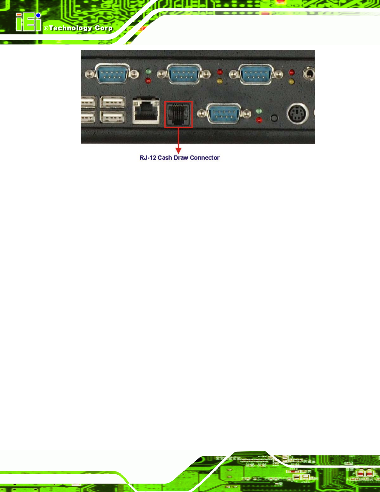
Figure 2-17: RJ-12 Connector
2.9 Wireless Connections
AFOLUX Kiosk Application Series
The following section describes the wireless modules on the circuit.
2.9.1 USB Bluetooth Module
An integrated Bluetooth module is connected to ICH7 chipset through the USB bus. The
AFL-315 Bluetooth module enables wireless communications between the AFL-315 and
various peripheral devices through a Bluetooth network. The peripheral devices may
include:
Headsets
Barcode readers
PDA
Printers
Cell phones
Keyboard and mouse
The Bluetooth module is shown in
Figure 2-18 below and the technical specifications of
Page 28
the Bluetooth module are listed in the Appendix.
Page 45

AFOLUX Kiosk Application Series
Figure 2-18: Bluetooth Module
2.9.2 Wireless Ethernet
An integrate PIFA antenna on the AFOLUX AFL-315 ensures an uninterrupted wireless
connection. PIFA antennas can receive high-quality, uniform signals in any location from
all directions without any signal degradation or impedance and are the most efficient
antennas on the market.
Page 29
Page 46

AFOLUX Kiosk Application Series
Figure 2-19: PIFA Antenna
2.10 Optional Modules
The following sections describe the optional module available to the user.
2.10.1 GPRS Module (Optional)
An optional GPRS module can be integrated into the AFL-315. The GPRS module is one
of the OEM options for the AFL-315 series. The technical specifications of the GPRS
module are listed in the Appendix.
2.11 System Ventilation
System ventilation is critical. Failure to ensure proper airflow through the system may
result in irreparable damage to the AFL-315. To help facilitate airflow through the
Page 30
AFL-315, the AFL-315 has three (labeled Fan 1, Fan 2 and Fan 6) 12 V, 3.0 A Everflow
cooling fans installed on the left side of the system. A further three air vents on the left side
of the system ensures air can flow through the system unobstructed.
Page 47

AFOLUX Kiosk Application Series
Figure 2-20: Internal View of Cooling Fans
The cooling fans are 50 mm x 50 mm x 10 mm in size. Fan specifications are listed in the
appendix.
Figure 2-21: Cooling Fan Dimensions
Page 31
Page 48

AFOLUX Kiosk Application Series
THIS PAGE IS INTENTIONALLY LEFT BLANK
Page 32
Page 49

AFOLUX Kiosk Application Series
Chapter
3
3 Unpacking
Page 33
Page 50

3.1 Unpacking
To unpack the flat panel PC, follow the steps below:
WARNING!
Step 1: Use box cutters, a knife or a sharp pair of scissors that seals the top side of the
AFOLUX Kiosk Application Series
The front side LCD screen has a protective plastic cover stuck to the
screen. Only remove the plastic cover after the flat panel PC has been
properly installed. This ensures the screen is protected during the
installation process.
external (second) box.
Step 2: Open the external (second) box.
Step 3: Use box cutters, a knife or a sharp pair of scissors that seals the top side of the
internal (first) box.
Step 4: Lift the monitor out of the boxes.
Step 5: Remove both polystyrene ends, one from each side.
Step 6: Pull the plastic cover off the flat panel PC.
Step 7: Make sure all the components listed in the packing list are present. Step 0:
3.1.1 Packing List
The AFL-315 flat panel PC is shipped with the following components:
Page 34
Page 51

AFOLUX Kiosk Application Series
Quantity Item Image
Standard
1 AFOLUX AFL-315
1 Power adapter
1 Power cord
1 User manual CD and driver CD
1 Touch pen
Optional
Panel mounting kit
(P/N: AFLPK-315A)
Wall mounting kit
(P/N: AFLWK-19)
Stand
(P/N:STAND-A19)
Page 35
Page 52

Stand
(P/N:STAND-B19)
AFOLUX Kiosk Application Series
Stand
(P/N: STAND-210-RS)
Arm
(P/N: ARM-11-RS)
Arm
(P/N: ARM-31-RS)
If any of these items are missing or damaged, contact the distributor or sales
representative immediately.
Page 36
Page 53

AFOLUX Kiosk Application Series
Chapter
4
4 Installation
Page 37
Page 54

4.1 Anti-static Precautions
WARNING:
Failure to take ESD precautions during the maintenance of the
AFL-315 may result in permanent damage to the AFL-315 and severe
injury to the user.
Electrostatic discharge (ESD) can cause serious damage to electronic components,
including the AFL-315. Dry climates are especially susceptible to ESD. It is therefore
critical that whenever the AFL-315 is accessed internally, or any other electrical
component is handled, the following anti-static precautions are strictly adhered to.
AFOLUX Kiosk Application Series
Wear an anti-static wristband: - Wearing a simple anti-static wristband can
help to prevent ESD from damaging the board.
Self-grounding:- Before handling the board touch any grounded conducting
material. During the time the board is handled, frequently touch any
conducting materials that are connected to the ground.
Use an anti-static pad: When configuring the AFL-315, place it on an
antic-static pad. This reduces the possibility of ESD damaging the AFL-315.
Only handle the edges of the PCB:-: When handling the PCB, hold the PCB
by the edges.
4.2 Installation Precautions
When installing the flat panel PC, please follow the precautions listed below:
Power turned off: When installing the flat panel PC, make sure the power is
off. Failing to turn off the power may cause severe injury to the body and/or
damage to the system.
Certified Engineers: Only certified engineers should install and modify
Page 38
onboard functionalities.
Mounting: The flat panel PC is a heavy device. When mounting the system
onto a rack, panel, wall or arm please make sure that at least two people are
Page 55

AFOLUX Kiosk Application Series
assisting with the procedure.
Anti-static Discharge: If a user open the rear panel of the flat panel PC, to
configure the jumpers or plug in added peripheral devices, ground themselves
first and wear and anti-static wristband.
4.3 Preinstalled Components
The following components are all preinstalled.
Motherboard
TFT LCD screen
1.0 GB DDR2 memory module
Resistive type touch screen
Wireless LAN module
Bluetooth module
AT/ATX power switch
Hard disk drive (HDD)
Preinstalled OEM customizations may include the following.
Different DDR2 memory module
Hard disk drive
GPRS module
Component installation is described in the following sections.
4.4 Installation and Configuration Steps
The following installation steps must be followed.
Step 1: Unpack the flat panel PC
Step 2: Install CF card
Step 3: Mount the flat panel PC
Step 4: Connect peripheral devices to the bottom panel of the flat panel PC
Step 5: Configure the systemStep 0:
Page 39
Page 56

4.5 Removing the Back Panel
To access the AFL-315 internally the back panel must be removed. To remove the back
panel, please follow the steps below.
AFOLUX Kiosk Application Series
Step 1: Remove the rear panel. Remove the seven retention screws (
the rear panel and lift the panel off the AFL-315.
Figure 4-1) from
Page 40
Figure 4-1: Rear Panel Retention Screws
Step 2: Remove the hard drive bracket. The HDD bracket is secured to the AFL-315
with four retention screws. See
Figure 4-2. Once the retention screws are
Page 57

AFOLUX Kiosk Application Series
removed, gently lift the HDD bracket. Step 0:
Figure 4-2: HDD Bracket Retention Screws
4.6 CF Card Installation
The AFL-315 series has one CF Type II slot. To install the CF card, follow the instructions
below.
Step 1: Remove the back panel. See Section
Step 2: Install the CF Card. Locate the CF card socket under the metal plate. Correctly
align the CF card with the socket and insert the CF card into the socket. See
Figure 4-3.
4.5.
Page 41
Page 58

AFOLUX Kiosk Application Series
Figure 4-3: CF Card Insert
Step 3: Reinstall the HDD bracket and the rear panel. Make sure the HDD bracket
and the rear panel are properly secured with the previously removed retention
screws.Step 0:
4.7 Jumper Settings
NOTE:
A jumper is a metal bridge used to close an
electrical circuit. It consists of two or three metal
pins and a small metal clip (often protected by a
plastic cover) that slides over the pins to connect
them. To CLOSE/SHORT a jumper means
connecting the pins of the jumper with the plastic
clip and to OPEN a jumper means removing the
plastic clip from a jumper.
Figure 4-4: Jumper Locations
Page 42
Page 59

AFOLUX Kiosk Application Series
The following jumpers can be found on the motherboard installed in the AFL-315. Before
the AFL-315 is installed, the jumpers must be set in accordance with the desired
configuration. The jumpers on the AFL-315 motherboard are listed in
Description Label Type
Clear CMOS JP1 2-pin header
COM1 Pin 9 setting JP8 3-pin header
COM4 Pin 9 setting JP5 3-pin header
COM5 Pin 9 setting JP6 3-pin header
COM6 Pin 9 setting JP7 3-pin header
COM6 RX RS-232/422/485 Select J6 6-pin header
COM6 TX RS-422/485 Select J7 6-pin header
COM6 D-SUB pin out select J11 12-pin header
Table 4-1: Jumpers
Table 4-1.
4.7.1 Access the Jumpers
To access the jumpers, remove the back panel. To remove the back panel, please refer to
Section
4.5.
4.7.2 Preconfigured Jumpers
WARNING:
Do not change the settings on the jumpers in described here. Doing so
may disable or damage the system
Page 43
Page 60
The following jumpers are preconfigured for the AFL-315. Users should no change these
jumpers.
Jumper Name Label Type
LVDS voltage selection JP4 3-pin header
Touch Screen Select J4 4-pin header
Panel Type and Resolution JP2 10-pin header
Table 4-2: Preconfigured Jumpers
4.7.3 Clear CMOS Jumper
AFOLUX Kiosk Application Series
Jumper Label:
Jumper Type: 2-pin header
Jumper Settings:
Jumper Location:
If the AFL-315 fails to boot due to improper BIOS settings, the clear CMOS jumper clears
the CMOS data and resets the system BIOS information. To do this, use the jumper cap to
close the pins for a few seconds then removel the jumper clip.
If the “CMOS Settings Wrong” message is displayed during the boot up process, the fault
may be corrected by pressing the F1 to enter the CMOS Setup menu. Do one of the
following:
Enter the correct CMOS setting
Load Optimal Defaults
Load Failsafe Defaults.
JP1
Table 4-3
See
Figure 4-5
See
Page 44
After having done one of the above, save the changes and exit the CMOS Setup menu.
The clear CMOS jumper settings are shown in
Table 4-3.
Page 61

AFOLUX Kiosk Application Series
AT Power Select Description
OPEN Keep CMOS Setup Default
SHORT Clear CMOS Setup
Table 4-3: Clear CMOS Jumper Settings
The location of the clear CMOS jumper is shown in Figure 4-5 below.
Figure 4-5: Clear CMOS Jumper
4.7.4 COM1 to COM6 Pin 9 Select
Jumper Label:
Jumper Type: 10-pin header
Jumper Settings:
Jumper Location:
Four jumpers (JP5, JP6, JP7 and JP8) configure pin 9 on COM1, COM4, COM5 and
COM6 DB-9 connectors. Pin 9 on the COM1 and the COM5 DB-9 connectors can be set
JP5, JP6, JP7 and JP8
See
See
Table 4-4
Figure 4-6
Page 45
Page 62

AFOLUX Kiosk Application Series
as either +5 V or +12 V. Pin 9 on the COM4 and COM6 DB-9 connectors can be set as
either +12 V or as the ring (RI) signal. The COM1, COM4, COM5 and COM6 Pin 9 Setting
jumper selection options are shown in
Short 1 – 2 Short 2 – 3 (Default)
JP5 COM4 RI Pin use +12 V COM4 RI Pin use RI
JP6 COM5 RI Pin use +12 V COM5 RI Pin use +5 V
JP7 COM6 RI Pin use +12 V COM6 RI Pin use RI
JP8 COM1 RI Pin use +12 V COM1 RI Pin use +5 V
Table 4-4.
Table 4-4: COM1, COM4, COM5 and COM6 Pin 9 Setting Jumper Settings
The COM1, COM4, COM5 and COM6 Pin 9 Setting jumper location are shown in Figure
4-6 below.
Figure 4-6: COM1, COM4, COM5 and COM6 Pin 9 Setting Jumper Location
4.7.5 COM6 RX Function Select Jumper
Page 46
Jumper Label:
Jumper Type: 6-pin header
J6
Page 63

AFOLUX Kiosk Application Series
Jumper Settings:
Jumper Location:
Table 4-5
See
Figure 4-7
See
The COM6 RX Function Select jumper sets the communication protocol used by the RX
serial communications port COM6 as RS-232, RS-422 or RS-485. The COM6 RX
Function Select jumper settings are shown in
COM6 RX Function Select Description
Short 1-2 RS-232 Default
Short 3-4 RS-422
Short 4-6 RS-485
Table 4-7.
Table 4-5: COM6 RX Function Select Jumper Settings
The COM6 RX Function Select jumper location is shown in Figure 4-9.
Figure 4-7: COM6 RX Function Select Jumper Location
4.7.6 COM6 TX Function Select Jumper
Jumper Label:
J7
Page 47
Page 64

AFOLUX Kiosk Application Series
Jumper Type: 6-pin header
Jumper Settings:
Jumper Location:
Table 4-6
See
Figure 4-8
See
The COM6 TX Function Select jumper configures the TX pin on COM6 serial port
connector as RS-422 as an RS-485. The COM6 TX Function Select jumper selection
options are shown in
AT Power Select Description
Short 1 – 3 RS-422 Default
Short 2 – 4 RS-422 Default
Short 3 – 5 RS-485
Short 4 – 6 RS-485
Table 4-6.
Table 4-6: COM6 TX Function Select Jumper Settings
The COM6 TX Function Select jumper location is shown in Figure 4-8 below.
Page 48
Figure 4-8: COM6 TX Function Select Jumper Pinout Locations
Page 65

AFOLUX Kiosk Application Series
4.7.7 COM6 RS-232/422/485 Serial Port Select Jumper
Jumper Label:
J11
Jumper Type: 12-pin header (four 3-pin headers combined)
Jumper Settings:
Jumper Location:
Table 4-7
See
Figure 4-9
See
The COM6 RS-232/422/485 Serial Port Select jumper sets the communication protocol
used by the second serial communications port (COM6) as RS-232, RS-422 or RS-485.
The COM6 RS-232/422/485 Serial Port Select settings are shown in
RS-232/485 Select Description
Short 1-2 RS-232 Default
Short 4-5 RS-232 Default
Short 7-8 RS-232 Default
Short 10-11 RS-232 Default
Short 2-3 RS-422/485
Table 4-7.
Short 5-6 RS-422/485
Short 8-9 RS-422/485
Short 11-12 RS-422/485
Table 4-7: COM6 RS-232/422/485 Serial Port Select Jumper Settings
The COM6 RS-232/422/485 Serial Port Select jumper location is shown in Figure 4-9.
Page 49
Page 66

AFOLUX Kiosk Application Series
Figure 4-9: COM6 RS-232/422/485 Serial Port Select Jumper Location
4.8 AT/ATX Mode Selection
AT and ATX power modes can both be used on the AFOLUX AFL-315 flat panel PC. The
selection is made through an AT/ATX switch on the aluminum chassis inside the plastic
back cover (
Step 1: Remove the plastic back cover. To do this, remove the 12 retention screws
Figure 4-11). To select AT mode or ATX mode, follow the steps below.
from the back cover.
Page 50
Page 67

AFOLUX Kiosk Application Series
Figure 4-10: Back Cover Retention Screws
Step 2: Locate the AT/ATX switch on the aluminum chassis (
Figure 4-11).
Page 51
Page 68

AFOLUX Kiosk Application Series
Figure 4-11: AT/ATX Switch
Step 3: Adjust the AT/ATX switch. The default mode is ATX mode with the switch being
pushed down. (
4.9 Mounting the System
WARNING!
When mounting the flat panel PC onto an arm, onto the wall or onto a
panel, it is better to have more than one person to help with the installation
to make sure the panel PC does not fall down and get damaged.
The four methods of mounting the AFOLUX AFL-315 are listed below.
Figure 4-11)Step 0:
Page 52
Wall mounting
Panel mounting
Arm mounting
Page 69

AFOLUX Kiosk Application Series
Rack mounting
The four mounting methods are described below.
4.9.1 Wall Mounting
To mount the flat panel PC onto the wall, please follow the steps below.
Step 1: Select the location on the wall for the wall-mounting bracket.
Step 2: Carefully mark the locations of the four screw holes in the bracket on the wall.
Step 3: Drill four pilot holes at the marked locations on the wall for the bracket retention
screws.
Step 4: Align the wall-mounting bracket screw holes with the pilot holes.
Step 5: Secure the mounting-bracket to the wall by inserting the retention screws into
the four pilot holes and tightening them (
Figure 4-12).
Figure 4-12: Wall-mounting Bracket
Step 6: Insert the four monitor mounting screws provided in the wall mounting kit into the
four screw holes on the real panel of the flat panel PC and tighten until the screw
shank is secured against the rear panel (
Figure 4-13).
Page 53
Page 70

Step 7: Align the mounting screws on the monitor rear panel with the mounting holes on
the bracket.
Step 8: Carefully insert the screws through the holes and gently pull the monitor
AFOLUX Kiosk Application Series
downwards until the monitor rests securely in the slotted holes (
Ensure that all four of the mounting screws fit snuggly into their respective
slotted holes.
Figure 4-13).
Page 54
Figure 4-13: Chassis Support Screws
NOTE:
In the diagram below the bracket is already installed on the wall.
Step 9: Secure the panel PC by fastening the retention screw of the wall-mounting
bracket. (
Figure 4-14).Step 0:
Page 71

AFOLUX Kiosk Application Series
Figure 4-14: Secure the Panel PC
4.9.2 Panel Mounting
To mount the AFOLUX AFL-315 series flat panel PC into a panel, please follow the steps
below.
Step 1: Select the position on the panel to mount the flat panel PC.
Step 2: Cut out a section from the panel that corresponds to the rear panel dimensions
of the flat panel PC. Take care that the panel section that is cut out is smaller
than the overall size of the metal frame that surrounds the flat panel PC but just
large enough for the rear panel of the flat panel PC to fit through (see
4-15).
Figure
Page 55
Page 72

AFOLUX Kiosk Application Series
Figure 4-15: AFL-315 Panel Opening
Step 3: Slide the flat panel PC through the hole until the frame is flush against the panel.
Step 4: Insert the panel mounting clamps into the pre-formed holes along the edges of
the chassis, behind the frame.
Step 5: Tighten the screws that pass through the panel mounting clamps until the plastic
caps at the front of all the screws are firmly secured to the panel (
Step 0:
Figure 4-16).
Page 56
Figure 4-16: Tighten the Panel Mounting Clamp Screws
Page 73

AFOLUX Kiosk Application Series
4.9.3 Arm Mounting
The AFOLUX AFL-315 series is VESA (Video Electronics Standards Association)
compliant and can be mounted on an arm with a 100mm interface pad. To mount the
AFOLUX AFL-315 series on an arm, please follow the steps below.
Step 1: The arm is a separately purchased item. Please correctly mount the arm onto
the surface it uses as a base. To do this, refer to the installation documentation
that came with the mounting arm.
NOTE:
When purchasing the arm please ensure that it is VESA compliant and that
the arm has a 100 mm interface pad. If the mounting arm is not VESA
compliant it cannot be used to support the AFOLUX AFL-315 series flat
panel PC.
Step 2: Once the mounting arm has been firmly attached to the surface, lift the flat panel
PC onto the interface pad of the mounting arm.
Step 3: Align the retention screw holes on the mounting arm interface with those in the
flat panel PC. The AFL-315 arm mount retention screw holes are shown in
Figure 4-17.
Page 57
Page 74

AFOLUX Kiosk Application Series
Figure 4-17: AFL-315 Arm Mounting Retention Screw Holes
Step 4: Secure the flat panel PC to the interface pad by inserting four retention screws
through the bottom of the mounting arm interface pad and into the flat panel PC.
Step 0:
4.9.4 Cabinet and Rack Installation
The AFL-315 series flat panel PC can be installed into a cabinet or rack. The installation
procedures are similar to the panel mounting installation. To do this, please follow the
steps below:
NOTE:
When purchasing the cabinet/rack installation bracket, make sure it is
compatible with both the AFL-315 series flat panel PC and the rack/cabinet
Page 58
into which the AFL LX series is installed.
Step 1: Slide the rear chassis of the AFL-315 series flat panel PC through the
Page 75

AFOLUX Kiosk Application Series
rack/cabinet bracket until the frame is flush against the front of the bracket
Figure 4-18).
(
Figure 4-18: The Rack/Cabinet Bracket
Step 2: Insert the rack mounting clamps into the pre-formed holes along the edges of
the flat panel PC, behind the ABS/PC plastic frame.
Step 3: Tighten the screws that pass through the rack mounting clamps until the plastic
caps at the front of all the screws are firmly secured to the bracket (
Figure 4-19).
Figure 4-19: Secure the Rack/Cabinet Bracket
Step 4: Slide the flat panel PC with the attached rack/cabinet bracket into a rack or
Page 59
Page 76

cabinet (Figure 4-20).
AFOLUX Kiosk Application Series
Figure 4-20: Install into a Rack/Cabinet
Step 5: Once the flat panel PC with the attached rack/cabinet bracket has been properly
inserted into the rack or cabinet, secure the front of the rack/cabinet bracket to
the front of the rack or cabinet (
4.10 Bottom Panel Connectors
4.10.1 LAN Connection
There is one external RJ-45 LAN connector. The RJ-45 connector enables connection to
an external network. To connect a LAN cable with an RJ-45 connector, please follow the
instructions below.
Step 1: Locate the RJ-45 connectors on the bottom panel of the AFOLUX AFL-315
Series.
Step 2: Align the connectors. Align the RJ-45 connector on the LAN cable with one of
Figure 4-20).Step 0:
Page 60
the RJ-45 connectors on the bottom panel of the AFOLUX AFL-315 Series. See
Figure 4-21.
Page 77

AFOLUX Kiosk Application Series
Figure 4-21: LAN Connection
Step 3: Insert the LAN cable RJ-45 connector. Once aligned, gently insert the LAN
cable RJ-45 connector into the onboard RJ-45 connector. Step 0:
4.10.2 Serial Device Connection
The AFOLUX AFL-315 Series has four male DB-9 connectors on the bottom panel for
serial devices to be connected. Follow the steps below to connect a serial device to the
AFOLUX AFL-315 Series panel PC.
Step 1: Locate the DB-9 connector. The location of the DB-9 connector is shown in
Chapter 2.
Step 2: Insert the serial connector. Insert the DB-9 connector of a serial device into
the DB-9 connector on the bottom panel. See
Figure 4-22.
Page 61
Page 78

AFOLUX Kiosk Application Series
Figure 4-22: Serial Device Connector
Step 3: Secure the connector. Secure the serial device connector to the external
interface by tightening the two retention screws on either side of the connector.
Step 0:
Page 62
Page 79

AFOLUX Kiosk Application Series
4.10.3 USB Device Connection
There are four external USB 2.0 connectors. All connectors are perpendicular to the
AFOLUX AFL-315 Series. To connect a USB 2.0 or USB 1.1 device, please follow the
instructions below.
Step 1: Located the USB connectors. The locations of the USB connectors are shown
in Chapter 2.
Step 2: Align the connectors. Align the USB device connector with one of the
connectors on the bottom panel. See
Figure 4-23.
Figure 4-23: USB Device Connection
Step 3: Insert the device connector. Once aligned, gently insert the USB device
connector into the onboard connector. Step 0:
Page 63
Page 80

4.11 Webcam Driver Installation
To install the webcam driver, please follow the instructions below.
Step 1: Run the CD that came with the AFL-315 on the AFL-315.
Step 2: Locate the Webcam installation program.
Step 3: Click the webcam driver installation icon
AFOLUX Kiosk Application Series
Step 4: The program prepares for installation. See
Figure 4-24.
Page 64
Figure 4-24: Preparing for Driver Installation
Step 5: When the driver is ready to be installed, the screen in
Figure 4-25 appears.
Page 81

AFOLUX Kiosk Application Series
Figure 4-25: Driver Installation Starting Screen
Step 6: Click N
Step 7: The program is ready for installation. See
EXT in Figure 4-25 to continue.
Figure 4-26.
Page 65
Page 82

AFOLUX Kiosk Application Series
Figure 4-26: Ready to Install Driver
Step 8: Click I
Step 9: The driver is then installed. See
NSTALL in Figure 4-26 to continue.
Figure 4-27.
Page 66
Page 83

AFOLUX Kiosk Application Series
Figure 4-27: Driver Installs
Step 10: Click Y
ES when asked for digital signature affirmation. See Figure 4-28.
Page 67
Page 84

AFOLUX Kiosk Application Series
Figure 4-28: Confirm Digital Signature
Step 11: The installation process is complete See
Figure 4-29. Click FINISH to confirm.
Page 68
Page 85

AFOLUX Kiosk Application Series
Figure 4-29: Installation Complete
Step 12: Restart the computer. See
Figure 4-30. Step 0:
Page 69
Page 86

AFOLUX Kiosk Application Series
Figure 4-30: Restart the computer.
Page 70
Page 87

AFOLUX Kiosk Application Series
Chapter
4
5 System Maintenance
Page 71
Page 88

AFOLUX Kiosk Application Series
5.1 System Maintenance Introduction
If the components of the AFOLUX AFL-315 series fail they must be replaced. Components
that can be replaced include:
CF Module
SATA HDD
Cooling Fans
Camera
Blue tooth module
Wireless LAN module
DIMM module
CPU
Please contact the system reseller or vendor to purchase the replacement parts. Back
cover removal instructions and jumper settings for the AFOLUX AFL-315 series are
described below.
5.2 Anti-static Precautions
WARNING:
Failure to take ESD precautions during the maintenance of the
AFL-315 may result in permanent damage to the AFL-315 and severe
injury to the user.
Electrostatic discharge (ESD) can cause serious damage to electronic components,
including the AFL-315. Dry climates are especially susceptible to ESD. It is therefore
critical that whenever the AFL-315 is accessed internally, or any other electrical
component is handled, the following anti-static precautions are strictly adhered to.
Page 72
Wear an anti-static wristband: - Wearing a simple anti-static wristband can
help to prevent ESD from damaging the board.
Self-grounding:- Before handling the board touch any grounded conducting
Page 89

AFOLUX Kiosk Application Series
material. During the time the board is handled, frequently touch any
conducting materials that are connected to the ground.
Use an anti-static pad: When configuring the AFL-315, place it on an
antic-static pad. This reduces the possibility of ESD damaging the AFL-315.
Only handle the edges of the PCB:-: When handling the PCB, hold the PCB
by the edges.
5.3 Turn off the Power
WARNING:
Failing to turn off the system before opening it can cause permanent
damage to the system and serious or fatal injury to the user.
Before any maintenance procedures are carried out on the system, make sure the system
is turned off.
5.4 Opening the System
5.4.1 Removing the Back Panel
To access the AFL-315 internally the back panel must be removed. To remove the back
panel, please follow the steps below.
Step 1: Follow all anti-static procedures. See Section
Step 2: Turn off the power. See Section
Step 3: Remove the retention screws on the back. Remove the five retention screws
Figure 4-1) from the rear panel.
(
5.2.
5.3.
Page 73
Page 90

AFOLUX Kiosk Application Series
Figure 5-1: Rear Panel Retention Screws (Back)
Step 4: Remove the retention screws from the bottom. Remove the two retention
screws from the bottom surface of the back panel. See
Figure 5-2.
Figure 5-2: Rear Panel Retention Screws (Bottom)
Step 5: Remove the rear panel. Gently lift the rear panel. Step 0:
Page 74
Page 91

AFOLUX Kiosk Application Series
5.4.2 Removing the Plastic Cover
To access the AT/ATX selection switch, the white/black plastic cover must be removed.
To do this,follow the steps below.
Step 1: Follow all anti-static procedures. See Section
Step 2: Turn off the power. See Section
Step 3: Remove the back panel. See Section
Step 4: Remove the plastic back cover. To do this, remove the 12 retention screws
from the back cover. See
Figure 5-3. Step 0:
5.3.
5.4.1.
5.2.
Figure 5-3: Back Cover Retention Screws
5.4.3 Removing the Metal Cover
To access the motherboard, the metal enclosure must be removed. To do this, follow the
steps below:
Page 75
Page 92

Step 1: Follow all anti-static procedures. See Section 5.2.
AFOLUX Kiosk Application Series
Step 2: Turn off the power. See Section
Step 3: Remove the back panel. See Section
Step 4: Remove the plastic cover. See Section
Step 5: Remove the retention screws. Ten retention screws secure the metal cover to
the system. Remove all ten retention screws.
5.3.
5.4.1.
5.4.2.
Page 76
Figure 5-4: Metal Enclosure Retention Screws
Step 6: Remove the 15 I/O connector retention screws. Use the screwdrivers shown
in to remove the COM port connector, DVI connector and audio jack retention
screws.
Page 93

AFOLUX Kiosk Application Series
Figure 5-5: Peripheral Interface Connector Screwdrivers
Figure 5-6: Peripheral Connector Retention Screws
Step 7: Remove the enclosure. Pull the metal enclosure up gently.Remember the CF
Flash card and the HDD cables are also connected to the system. So when
removing the enclosure, do so gently. Step 0:
Page 77
Page 94

AFOLUX Kiosk Application Series
5.4.4 Removing the Processor and DIMM Housing
To access the CPU module and the DIMM modules, the plastic housing needs to be
removed.
Step 1: Follow all anti-static procedures. See Section
Step 2: Turn off the power. See Section
Step 3: Remove the back panel. See Section
Step 4: Remove the plastic cover. See Section
Step 5: Remove the metal enclosure. See Section
Step 6: Remove the retention screws. Four retention screws secure the processor
and DIMM housing to the system. Remove all four retention screws. See
5-7. Step 0:
5.3.
5.4.1.
5.4.2.
5.2.
5.4.3.
Figure
Page 78
Figure 5-7: Processor and DIMM Housing
Step 1: Remove the cable. Remove the SATA cable, the SATA power cable and the CF
Flash card IDE cable.
Step 2: Remove the HDD bracket. See Section
5.2.
Page 95
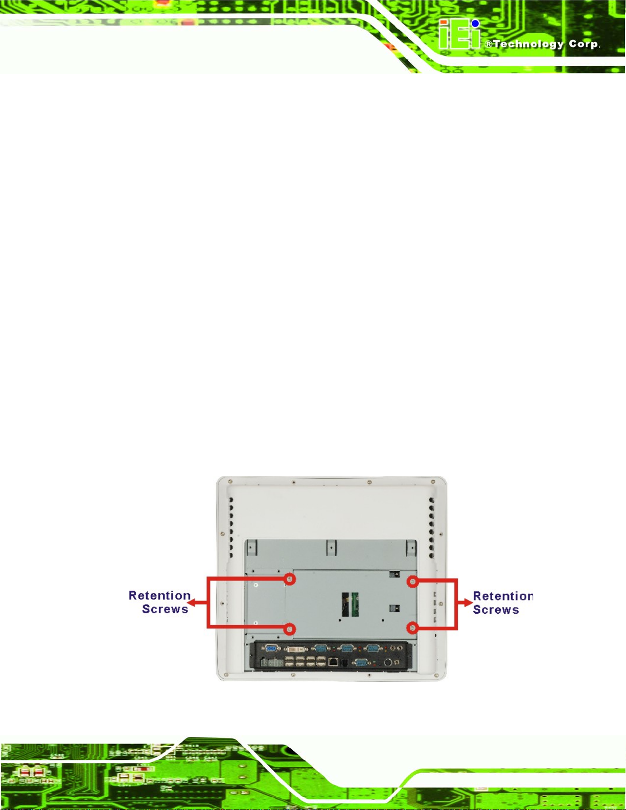
AFOLUX Kiosk Application Series
Step 3: Remove the retention screws. Remove the twelve retention screws that
secure the metal frame to the system.
Step 4: Remove the I/O interface screws. Remove the twelve retention screws that
secure the I/O connectors to the system.
Step 5: Remove the frame. Gently lift the frame off the system. Step 0:
5.5 Replacing Components
5.5.1 Hard Disk Drive Replacement
If the HDD fails, please follow the steps below:
Step 1: Follow all anti-static procedures. See Section
Step 2: Turn off the power. See Section
Step 3: Remove the back panel. See Section
Step 4: Remove the hard drive bracket. The HDD bracket is secured to the AFL-315
with four retention screws. See
removed, gently lift the HDD bracket.
5.3.
5.4.1.
Figure 5-8. Once the retention screws are
5.2.
Figure 5-8: HDD Bracket Retention Screws
Page 79
Page 96

Step 5: Disconnect the HDD. Remove both the SATA drive cable and the SATA power
cable from the motherboard.
Step 6: Remove the HDD retention screws. Remove the four retention screws from
the side of the HDD bracket that secure the HDD to the HDD bracket.
AFOLUX Kiosk Application Series
Figure 5-9: HDD Retention Screws
Step 7: Remove the HDD from the bracket. Slide the HDD out of the bracket.
Step 8: Install the new HDD. Slide the new HDD into the bracket and secure the new
HDD in the bracket with the four previously removed retention screws.
Step 9: Reinstall the cables. Reconnect the SATA cable and the SATA power cable to
the motherboard.
Step 10: Reinstall the HDD bracket. Secure the HDD bracket to the system with the four
previously removed retention screws. Step 0:
5.5.2 CF Card Replacement
The AFOLUX AFL-315 series has one CF Type II slot. To replace the CF card, follow the
instructions below.
Page 80
Step 1: Follow all anti-static procedures. See Section
Step 2: Turn off the power. See Section
5.3.
5.2.
Page 97

AFOLUX Kiosk Application Series
Step 3: Remove the back panel. See Section 5.4.1.
Step 4: Remove the hard drive bracket. See Section
Step 5: Remove the CF Card. Locate the CF card under the metal plate. Pull the CF
card out of the system. See
Figure 5-10.
5.5.1.
Figure 5-10: Locate the CF Card
Step 6: Install the replacement CF card. Correctly align the new CF Card with the CF
card socket and slide the new CF Card into the CF Card Socket.
Step 7: Reinstall the HDD bracket and the rear panel. Make sure the HDD bracket
and the rear panel are properly secured with the previously removed retention
screws.Step 0:
Page 81
Page 98

5.5.3 DIMM Module Replacement
WARNING:
Using incorrectly specified DIMM may cause permanently damage the
AFL-315. Please make sure the purchased DIMM complies with the
memory specifications of the AFL-315.
To replace the DIMM module, please follow the steps below.
AFOLUX Kiosk Application Series
Step 1: Follow all anti-static procedures. See Section
Step 2: Turn off the power. See Section
Step 3: Remove the back panel. See Section
Step 4: Remove the plastic cover. See Section
Step 5: Remove the metal enclosure. See Section
Step 6: Remove the processor and DIMM housing. See Section
Step 7: Locate the DIMM module. The DIMM module is located above the CPU
module. See
Figure 5-11.
5.3.
5.4.1.
5.4.2.
5.2.
5.4.3.
5.4.4.
Page 82
Page 99

AFOLUX Kiosk Application Series
Figure 5-11: DIMM Socket Location
Step 8: Open the DIMM socket handles. The DIMM socket has two handles that
secure the DIMM into the socket. Before the DIMM can be removed from the
socket, the handles must be opened.
Step 9: Open the DIMM socket handles. The DIMM socket has two handles that
secure the DIMM into the socket. Before the DIMM can be inserted into the
socket, the handles must be opened. See
Figure 5-12.
Page 83
Page 100

AFOLUX Kiosk Application Series
Figure 5-12: Installing a DIMM
Step 10: Align the DIMM with the socket. The DIMM must be oriented in such a way
that the notch in the middle of the DIMM must be aligned with the plastic bridge
in the socket. See
Step 11: Insert the DIMM. Once properly aligned, the DIMM can be inserted into the
socket. As the DIMM is inserted, the white handles on the side of the socket will
close automatically and secure the DIMM to the socket. See
Step 0:
Figure 5-12.
Figure 5-12.
5.5.4 CPU Replacement
To replace the CPU, please do the following.
Step 1: Follow all anti-static procedures. See Section
Step 2: Turn off the power. See Section
Step 3: Remove the back panel. See Section
5.3.
5.4.1.
5.2.
Page 84
Step 4: Remove the plastic cover. See Section
Step 5: Remove the metal enclosure. See Section
5.4.2.
5.4.3.
 Loading...