


AFL3-12C-ULT3 Panel PC
Page I
AFL3-12C-ULT3
MODEL:
Flat Bezel Panel PC with Intel® Core™ i5-6300U / Celeron® 3855U
Rev. 1.00 - M ay 7, 2018
CPU, Tou chscreen, Four USB Ports, Dual GbE LAN,
RS-232/422/485, HDMI, Wi-Fi 802.1 1a/b/g/n/ac and RoHS
User Manual
User Manual

AFL3-12C-ULT3 Panel PC
Page II
Date Version Changes
May 7, 2018 1.00 Initial release
Revision

AFL3-12C-ULT3 Panel PC
Page III
Warning! To prevent the system from overheating, do not operate it in an area that
Safety Instructions
Warning! Read the user manual before connecting the system to the power
source.
Vorsicht! Bitte lesen Sie die Bedienungsanleitung, bevor Sie das System an eine
Stromquelle anschließen.
Attention! Avant de brancher le système à la source d'alimentation, consultez le
mode d'emploi.
Avvertenza! Consultare il manuale utente prima di collegare il sistema
all'alimentatore.
Atención! Lea atentamente este manual del usuario antes de operar la fuente de
alimentación.
警告!在將系統連接到電源之前,請仔細閱讀使用手冊。
警告!在将系统连接到电源之前,请仔细阅读使用手册。
exceeds the maximum operating temperature described in the user manual.
Vorsicht! Um eine Überhitzung des Systems zu vermeiden, betreiben Sie es
ausschließlich im zulässigen Betriebstemperaturbereich. Dieser ist in der
Bedienungsanleitung vermerkt.
Attention! Pour éviter la surchauffe du système, ne l'utilisez pas dans une zone
dont la température dépasse les limites décrits dans le mode d'emploi.
Avvertenza! Per evitare che il sistema si surriscaldi, non utilizzarlo in aree che
superino la temperatura massima d'esercizio descritta nel manuale utente.
Atención! Para evitar el excesivo calentamiento del sistema, no opere en las
condiciones de temperatura superior a lo recomendado en este manual del
usuario.
警告!為防止系統過熱,不要在使用手冊上記載的產品工作溫度範圍之外操作此系
統。
警告!为防止系统过热,不要在使用手册上记载的产品工作温度范围之外操作此系
统。

AFL3-12C-ULT3 Panel PC
Page IV
源适配器将可能导致火灾或爆炸。电源适配器规格请参考使用手册。
Warning! Use only the adapter and power cord approved for this system. Use of
another type of adapter may risk fire or explosion. Please refer to the user manual
for the power adapter specifications.
Vorsicht! Nur zugelassene Netzteile und Netzkabel dürfen verwendet werden. Die
Benutzung von anderen Netzteilen kann einen Brand oder eine Explosion zur
Folge haben. Prüfen Sie die jeweiligen Spezifikationen in der
Bedienungsanleitung.
Attention! Utilisez exclusivement le câble d'alimentation et l’adaptateur
homologués pour ce système. L’utilisation d’un autre type d’adaptateur risquerait
de provoquer un incendie ou une explosion. Veuillez référer au mode d'emploi
pour les spécifications de l'adaptateur d'alimentation.
Avvertenza! Utilizzare solo l'adattatore e il cavo di alimentazione approvati per
questo sistema. L'uso di un altro tipo di adattatore può causare rischio d'incendio
o esplosione. Si prega di fare riferimento al manuale utente per le specifiche
sull'alimentazione.
Atención! Utilice solamente el adaptador de corriente alterna (CA) con Marcas
Conformidad otorgadas. Cualquier otro adaptador no otorgado aumenta el riesgo
de explosión o incendio. Por favor consulte el manual del usuario para las
especificaciones del adaptador de alimentación.
警告!只能使用經過認證、適用於本系統的電源變壓器與電源線。使用不適用的電
源變壓器將可能導致火災或爆炸。電源變壓器規格請參考使用手冊。
警告!只能使用经过认证,适用于本系统的电源适配器与电源线。使用不适用的电
Warning! Ultimate disposal of this product should be handled according to all
national laws and regulations.
Vorsicht! Die Entsorgung dieses Produkts sollte gemäß allen Bestimmungen und
Gesetzen des Landes erfolgen.
Attention! La mise au rebut ou le recyclage de ce produit sont généralement
soumis aux lois et/ou directives de respect de l'environnement. Renseignez-vous
auprès de l'organisme compétent.
Avvertenza! Lo smaltimento di questo prodotto deve essere eseguito secondo le
leggi e i regolamenti locali.
Atención! La disposición final de residuos de este producto se debe cumplir con
las normativas y leyes del país.
警告!本產品的廢棄處理應根據該國家的法律和規章進行。
警告!本产品的废弃处理应根据该国家的法律和规章进行。

AFL3-12C-ULT3 Panel PC
Page V
Copyright
COPYRIGHT NOTICE
The information in this document is subject to change without prior notice in order to
improve reliability, design and function and does not represent a commitment on the part
of the manufacturer.
In no event will the manufacturer be liable for direct, indirect, special, incidental, or
consequential damages arising out of the use or inability to use the product or
documentation, even if advised of the possibil ity of such damages.
This document contains proprietary information protected by copyright. All rights are
reserved. No part of this manual may be reproduced by any mechanical, electronic, or
other means in any form without prior written permission of the manufacturer.
TRADEMARKS
All registered trademarks and product names mentioned herein are used for identification
purposes only and may be trademarks and/or registered trademarks of their respective
owners.

AFL3-12C-ULT3 Panel PC
Page VI
Manual Conventions
WARNING
Warnings appear where overlooked details may cause damage to the
equipment or result in personal injury. Warnings should be taken
seriously.
CAUTION
Cautionary messages should be heeded to help red uce the chance of
losing data or damaging the product.
NOTE
These messages inform the reader of essenti al but non-critical
information. These messages should be read carefully as any directions
or instructions contained therein can help avoid making mistakes.
HOT SURFACE
This symbol indicates a hot surface that shoul d not be touched without
taking care.

AFL3-12C-ULT3 Panel PC
Page VII
Table of Contents
1 INTRODUCTION .......................................................................................................... 1
1.1 OVERVIEW .................................................................................................................. 2
1.2 MODEL VARIATIONS ................................................................................................... 3
1.3 FEATURES ................................................................................................................... 3
1.4 FRONT PANEL ............................................................................................................. 4
1.5 BOTTOM PANEL .......................................................................................................... 5
1.6 REAR PANEL ............................................................................................................... 5
1.7 SIDE PANEL ................................................................................................................ 6
1.8 SYSTEM SPECIFICATIONS ............................................................................................ 6
1.9 DIMENSIONS ............................................................................................................... 9
2 UNPACKING ............................................................................................................... 10
2.1 UNPACKING ............................................................................................................... 11
2.2 PACKING LIST ............................................................................................................ 11
2.3 OPTIONAL ITEMS ...................................................................................................... 13
3 INSTALLATION ......................................................................................................... 15
3.1 ANTI-STATIC PRECAUTIONS ...................................................................................... 16
3.2 INSTALLATION PRECAUTIONS ................................................................................... 16
3.3 INSTALLATION AND CONFIGURATION STEPS ............................................................. 17
3.4 REMOVING THE BACK COVERS ................................................................................ 17
3.5 MSATA MODULE INSTALLATION .............................................................................. 18
3.6 HDD INSTALLATION ................................................................................................. 21
3.7 SERIAL PORT CONFIGURA TION AND CONNECTION .................................................... 23
3.7.1 RS-232 Serial Port Connection ........................................................................ 23
3.7.1.1 RS-232 Serial Port Pinouts ....................................................................... 24
3.7.2 RS-232/422/485 Serial Port Connection ......................................................... 24
3.8 AT/ATX MODE SELECTION ...................................................................................... 25
3.8.1 AT Power Mode ................................................................................................ 25
3.8.2 ATX Power Mode ............................................................................................. 26
3.9 MOUNTING THE SYSTEM .......................................................................................... 26

AFL3-12C-ULT3 Panel PC
Page VIII
3.9.1 Wall Mounting .................................................................................................. 26
3.9.2 Panel Mounting ................................................................................................ 30
3.9.3 Cabinet and Rack Installation ......................................................................... 33
3.9.4 Arm Mounting .................................................................................................. 36
3.9.5 Stand Mounting ................................................................................................ 38
3.10 POWERING ON THE SYSTEM ................................................................................... 39
3.11 RESET THE SYSTEM ................................................................................................ 40
3.12 SOFTWARE INSTALLATION ...................................................................................... 41
3.13 DRIVER DOWNLOAD .............................................................................................. 42
3.14 INSTALLING WINDOWS 7 FROM USB 3.0 DRIVES ................................................... 43
4 BIOS SETUP ................................................................................................................ 45
4.1 INTRODUCTION ......................................................................................................... 46
4.1.1 Starting Setup ................................................................................................... 46
4.1.2 Using Setup ...................................................................................................... 46
4.1.3 Getting Help ..................................................................................................... 47
4.1.4 BIOS Menu Bar ................................................................................................ 47
4.2 MAIN ........................................................................................................................ 48
4.3 ADVANCED ............................................................................................................... 49
4.3.1 ACPI Settings ................................................................................................... 50
4.3.2 Super IO Configuration ................................................................................... 51
4.3.2.1 Serial Port n Configuration ....................................................................... 51
4.3.2.1.1 Serial Port 1 Configuration ................................................................ 52
4.3.2.1.2 Serial Port 2 Configuration ................................................................ 53
4.3.1 Hardware Monitor ........................................................................................... 54
4.3.2 iWDD H/W Monitor ......................................................................................... 55
4.3.3 RTC Wake Settings ........................................................................................... 56
4.3.4 Serial Port Console Redirection ...................................................................... 57
4.3.4.1 Legacy Console Redirection Settings ....................................................... 58
4.3.4.2 Console Redirection Settings .................................................................... 59
4.3.5 CPU Configuration .......................................................................................... 61
4.3.6 SATA Configuration ......................................................................................... 63
4.3.7 USB Configuration ........................................................................................... 65
4.3.8 IEI Feature ....................................................................................................... 66
4.4 CHIPSET ................................................................................................................... 67

AFL3-12C-ULT3 Panel PC
Page IX
4.4.1 System Agent (SA) Configuration .................................................................... 67
4.4.1.1 Graphics Configuration ............................................................................. 68
4.4.1.1.1 LCD Control ...................................................................................... 69
4.4.1.2 Memory Configuration ............................................................................. 70
4.4.2 PCH-IO Configuration .................................................................................... 71
4.4.2.1 PCI Express Configuration ....................................................................... 72
4.4.2.2 HD Audio Configuration ........................................................................... 73
4.5 SECURITY ................................................................................................................. 74
4.6 BOOT ........................................................................................................................ 75
4.7 SAVE & EXIT ............................................................................................................ 77
5 SYSTEM MAINTENANCE ....................................................................................... 79
5.1 SYSTEM MAINTENANCE INTRODUCTION .................................................................. 80
5.2 ANTI-STATIC PRECAUTIONS ...................................................................................... 80
5.3 TURN OFF THE POWER .............................................................................................. 81
5.4 SO-DIMM MODULE REPLACEMENT........................................................................ 81
6 INTERFACE CONNECTORS ................................................................................... 84
6.1 PERIPHERAL INTERFACE CONNECTORS ..................................................................... 85
6.2 INTERNAL PERIPHERAL CONNECTORS ...................................................................... 86
6.2.1 Audio Connector (AUDIO_OUT1) .................................................................. 87
6.2.2 Audio Out Connector (AUDIO_OUT_L1) ....................................................... 87
6.2.1 Audio Out Connector (AUDIO_OUT_R1) ....................................................... 88
6.2.2 Battery Connector (BAT1) ............................................................................... 88
6.2.3 Digital I/O Connector (DIO1) ......................................................................... 89
6.2.1 Fan Connector (CPU/FAN1) ........................................................................... 89
6.2.2 Inverter Connector (INVERTER1) ................................................................... 89
6.2.3 LVDS Connector (LVDS1) ............................................................................... 90
6.2.4 Microphone Connector (DMIC1) .................................................................... 90
6.2.5 PCIe Mini Connector, Full-Size/Half-size (M_PCIE1) ................................... 91
6.2.6 Power Button Connector (PWR_BTN1) .......................................................... 92
6.2.7 Power LED Connector (PW_LED1) ................................................................ 92
6.2.8 SATA Connector (SATA1) ................................................................................. 92
6.2.9 USB Connector (HUB_USB1) ......................................................................... 93
6.2.10 USB Connector (CAM_USB1) ....................................................................... 93

AFL3-12C-ULT3 Panel PC
Page X
6.2.11 USB Connector (RFID_USB1)....................................................................... 93
6.2.12 USB Connector (TOUCH_USB1) .................................................................. 94
6.2.13 USB Power Connector (USB_HUB_P1) ....................................................... 94
6.2.1 U72 Firmware Programming Connector (JP1) ............................................... 94
6.2.1 Debug Connector (DBG_PORT1) ................................................................... 95
6.2.1 Debug Connector, EC (LPT_DB1) .................................................................. 95
6.2.1 SPI Flash Connector (JSPI1) ........................................................................... 95
6.2.1 SPI Flash Connector, EC (JSPI2) .................................................................... 96
6.2.2 Touch Panel Connector (TOUCH1) ................................................................. 96
6.3 EXTERNAL INTERFACE PANEL CONNECTORS ............................................................ 97
6.3.1 Ethernet Connectors (LAN1 & LAN2) ............................................................. 97
6.3.2 HDMI Connector (HDMI1) ............................................................................. 98
6.3.3 Power Connector (PWR1) ............................................................................. 98
6.3.1 RS-232 RJ-45 Serial Port (COM1) .................................................................. 98
6.3.2 RS-232/422/485 DB-9 Serial Port (COM2) ..................................................... 99
6.3.3 USB 3.0 Connectors (USB3_CON1) ................................................................ 99
6.3.4 USB 2.0 Connectors (USB2_CON1) .............................................................. 100
6.4 PRECONFIGURED JUMPER SETTINGS ....................................................................... 100
6.4.1 LVDS Panel Voltage Selection Jumper (J_VLVDS1) ..................................... 101
6.4.2 LVDS Panel Resolution Selection Jumper (SW1) .......................................... 101
6.4.3 Flash Descriptor Security Override Jumper .................................................. 102
A REGULATORY COMPLIANCE ............................................................................ 103
B SAFETY PRECAUTIONS ....................................................................................... 109
B.1 SAFETY PRECAUTIONS ............................................................................................ 110
B.1.1 General Safety Precautions ............................................................................ 110
B.1.2 Anti-static Precautions ................................................................................... 111
B.1.3 Product Disposal ............................................................................................ 112
B.2 MAINTENANCE AND CLEANING PRECAUTIONS ....................................................... 113
B.2.1 Maintenance and Cleaning ............................................................................. 113
B.2.2 Cleaning Tools ................................................................................................ 113
C BIOS MENU OPTIONS ............................................................................................ 115
D WATCHDOG TIMER ............................................................................................... 118
E HAZARDOUS MATERIALS DISCLOSURE ....................................................... 121

AFL3-12C-ULT3 Panel PC
Page XI
List of Figures
Figure 1-1: AFL3-12C-ULT3 Flat Bezel Panel PC ......................................................................... 2
Figure 1-2: Front View .................................................................................................................... 4
Figure 1-3: Bottom Panel ............................................................................................................... 5
Figure 1-4: Rear View ..................................................................................................................... 5
Figure 1-5: Side View...................................................................................................................... 6
Figure 1-6: Dimensions (mm) ........................................................................................................ 9
Figure 3-1: Back Cover Retention Screws ................................................................................. 17
Figure 3-2: Aluminum Cover Retention Screws ........................................................................ 18
Figure 3-3: mSATA Module Slot Location .................................................................................. 19
Figure 3-4: Removing the Retention Screw and Standoff ........................................................ 19
Figure 3-5: Installing an mSATA Module ................................................................................... 20
Figure 3-6: Securing the mSATA Module ................................................................................... 20
Figure 3-7: HDD Bracket Retention S c r ews ............................................................................... 21
Figure 3-8: HDD Retention Screws ............................................................................................. 22
Figure 3-9: HDD Installation ........................................................................................................ 22
Figure 3-10: Serial Device Connector ......................................................................................... 24
Figure 3-11: AT/ATX Switch Location ......................................................................................... 25
Figure 3-12: Wall-mounting Bracket ........................................................................................... 27
Figure 3-13: Chassis Support Screws ........................................................................................ 29
Figure 3-14: Secure the Panel PC ............................................................................................... 29
Figure 3-15: Cutout Dimensions ................................................................................................. 30
Figure 3-16: Panel Mounting Kit Installation ............................................................................. 31
Figure 3-17: Securing Panel Mounting Brackets ....................................................................... 32
Figure 3-18: Rack Mounting Kit Installation .............................................................................. 34
Figure 3-19: Securing Rack Mounting Brackets ........................................................................ 35
Figure 3-20: Install into a Rack/Cabinet ..................................................................................... 35
Figure 3-21: Arm Mounting Retention Screw Holes .................................................................. 37
Figure 3-22: Arm Mounting .......................................................................................................... 37
Figure 3-23: Stand Mounting (Stand-A/Bxx) .............................................................................. 38
Figure 3-24: Powering On the System ........................................................................................ 39
Figure 3-25: Reset Button Location ............................................................................................ 40

AFL3-12C-ULT3 Panel PC
Page XII
Figure 3-26: IEI Resource Download Center .............................................................................. 41
Figure 5-1: SO-DIMM module Location ...................................................................................... 82
Figure 5-2: SO-DIMM Installation ................................................................................................ 82
Figure 6-1: Main Board Layout Diagram .................................................................................... 85

AFL3-12C-ULT3 Panel PC
Page XIII
List of Tables
Table 1-1: Model Variations ........................................................................................................... 3
Table 1-2: System Specifications .................................................................................................. 8
Table 3-1: RS-232 Serial Port (COM1) Pinouts .......................................................................... 24
Table 3-2: RS-232/422/485 Serial Port (COM2) Pinouts ............................................................ 25
Table 6-1: Peripheral Interface Connectors ............................................................................... 87
Table 6-2: Audio Connector (AUDIO_OUT1) Pinouts ................................................................ 87
Table 6-3: Audio Out Connector (AUDIO_OUT_L1) Pinouts .................................................... 87
Table 6-4: Audio Out Connector (AUDIO_OUT_R1) Pinouts .................................................... 88
Table 6-5: Battery Connector (BAT1) Pinouts ........................................................................... 88
Table 6-6: Digital I/O Connector (DIO1) Pinouts ........................................................................ 89
Table 6-7: Fan Connector (CPU/FAN1) Pinouts ......................................................................... 89
Table 6-8: Inverter Connector (INVERTER1) Pinouts ................................................................ 89
Table 6-9: LVDS Connector (LVDS1) Pinouts ............................................................................ 90
Table 6-10: Microphone Connector (DMIC1) Pinouts ............................................................... 90
Table 6-11: PCIe Mini Connector (M_PCIE1) Pinouts ............................................................... 91
Table 6-12: Power Button Connector (PWR_BTN1) Pinouts .................................................... 92
Table 6-13: Power LED Connector (PW_LED1) Pinouts ........................................................... 92
Table 6-14: SATA Connector (SATA1) Pinou ts ......................................................................... 92
Table 6-15: USB Connector (HUB_USB1) Pinouts .................................................................... 93
Table 6-16: USB Connector (CAM_USB1) Pinouts .................................................................... 93
Table 6-17: USB Connector (RFID_USB1) Pinouts ................................................................... 93
Table 6-18: USB Connector (TOUCH_USB1) Pinouts ............................................................... 94
Table 6-19: USB Power Connector ( USB_USB_P1) Pinouts .................................................... 94
Table 6-20: U72 Firmware Programming Connector (JP1) Pinouts ........................................ 94
Table 6-21: Debug Connector (DBG_PORT1 ) Pinouts .............................................................. 95
Table 6-22: EC Debug Connector (LPT_DB1) Pinouts .............................................................. 95
Table 6-23: SPI Flash Connector (JSPI1) Pinouts ..................................................................... 96
Table 6-24: EC SPI Flash Connector (JSPI2) Pinouts ............................................................... 96
Table 6-25: Touch Panel Connector (TOUCH1) Pinouts ........................................................... 96
Table 6-26: Rear Panel Connectors ............................................................................................ 97
Table 6-27: Ethernet Connectors (LAN1 & LAN2) Pinouts ....................................................... 97

AFL3-12C-ULT3 Panel PC
Page XIV
Table 6-28: HDMI Connector (HDMI1) Pinouts ........................................................................... 98
Table 6-29: Power Connector (PWR1) Pinouts .......................................................................... 98
Table 6-30: RS-232 RJ-45 Serial Port (COM1) Pinouts .............................................................. 98
Table 6-31: RS-232/422/485 DB-9 Serial Port (COM2) Pinouts ................................................. 99
Table 6-32: USB 3.0 Connectors ( USB_CON12) Pinouts .......................................................... 99
Table 6-33: USB 2.0 Connectors ( USB2_CON1) Pinouts ........................................................100
Table 6-34: Preconfigured Jumpers .........................................................................................100
Table 6-35: LVDS Voltage Selection Jumper (J_VLVDS1) Settings ......................................101
Table 6-36: LVDS Resolution Selection Jump er (SW1) Settings ...........................................101
Table 6-37: Flash Descriptor Security Override Jumper Settings .........................................102

AFL3-12C-ULT3 Panel PC
Page XV
List of BIOS Menus
BIOS Menu 1: Main ....................................................................................................................... 48
BIOS Menu 2: Advanced .............................................................................................................. 49
BIOS Menu 3: ACPI Settings ....................................................................................................... 50
BIOS Menu 4: Super IO Configuration ........................................................................................ 51
BIOS Menu 5: Serial Port n Configuration ................................................................................. 51
BIOS Menu 6: Hardware Monitor ................................................................................................. 54
BIOS Menu 7: iWDD H/W Monitor ............................................................................................... 55
BIOS Menu 8: RTC Wake Settings .............................................................................................. 56
BIOS Menu 9: Serial Port Console Redirection ......................................................................... 57
BIOS Menu 10: Legacy Console Redirection Settings ............................................................. 58
BIOS Menu 11: Console Redirection Settings ........................................................................... 59
BIOS Menu 12: CPU Configuration ............................................................................................. 61
BIOS Menu 13: SATA Configuration ........................................................................................... 63
BIOS Menu 14: USB Configuration ............................................................................................. 65
BIOS Menu 15: IEI Feature ........................................................................................................... 66
BIOS Menu 16: Chipset ................................................................................................................ 67
BIOS Menu 17: System Agent (SA) Configuration .................................................................... 67
BIOS Menu 18: Graphics Configuration ..................................................................................... 68
BIOS Menu 19: LCD Control ........................................................................................................ 69
BIOS Menu 20: Memory Configuration ....................................................................................... 70
BIOS Menu 21: PCH-IO Configuration ........................................................................................ 71
BIOS Menu 22: PCI Express Configuration ............................................................................... 72
BIOS Menu 23: HD Audio Configuration .................................................................................... 73
BIOS Menu 24: Security ............................................................................................................... 74
BIOS Menu 25: Boot ..................................................................................................................... 75
BIOS Menu 26: Save & Exit .......................................................................................................... 77


AFL3-12C-ULT3 Panel PC
Page 1
Chapter
1
1 Introduction

AFL3-12C-ULT3 Panel PC
Page 2
1.1 Overview
Figure 1-1: AFL3-12C-ULT3 Flat Bezel Panel PC
The AFL3-12C-ULT3 series is a quad-core Intel
3855U powered flat bezel touchscreen panel PC with a rich variety of functions and
peripherals. The flat-bezel design is ideal for easy and simplified integration into various
applications.
The Intel
optimal memory, graphics, and peripheral I/O support. The system comes with 4.0 GB of
DDR4 SO-DIMM memory ensuring smooth data throughputs with reduced bottlenecks
and fast system access.
One RS-232/422/485 serial port, one RS-232 serial port and four external USB ports
ensure simplified connectivity to a variety of external peripheral devices. Wi-Fi capabilities
and two RJ-45 Ethernet connectors provide the system with smooth connection to an
external LAN.
®
Core™ i5-6300U / Celeron® 3855U is a System-on-Chip (SoC) that ensures
®
Core™ i5-6300U or Intel® Celeron®

AFL3-12C-ULT3 Panel PC
Page 3
1.2 Model Variations
There are several models in the AFL3-12C-ULT3 series. The model numbers and model
variations are listed below.
Model Processor
AFL3-12C-ULT3-C/PC/4G
AFL3-12C-ULT3-i5/PC/4G
Table 1-1: Model Variations
1.3 Features
The AFL3-12C-ULT3 features are listed below:
Flat-bezel LCD with LED backlight
Intel
Preinstalled with 4 GB of DDR4 memory (system max. 8 GB)
Projected capacitive type touchscreen
Wi-Fi 802.11a/b/g/n/ac high speed wireless
Two PCIe GbE RJ-45 connectors
Two internal speakers
Two USB 3.0 ports and two USB 2.0 ports
®
Celeron® 3855U (2M cache, 1.60 GHz)
Intel
®
Core™ i5-6300U (3M cache, up to 3.00 GHz)
Intel
®
Core™ i5-6300U or Intel® Celeron® 3855U processor
One RS-232/422/485 serial port by D-sub 9 connector and one RS-232 serial
port by RJ-45 connector
Optional RFID reader
Optional magnetic stripe card reader
12 V–30 V wide range DC power input
IP 64 compliant front panel
AFL3-12C-ULT3 Panel PC
Page 4
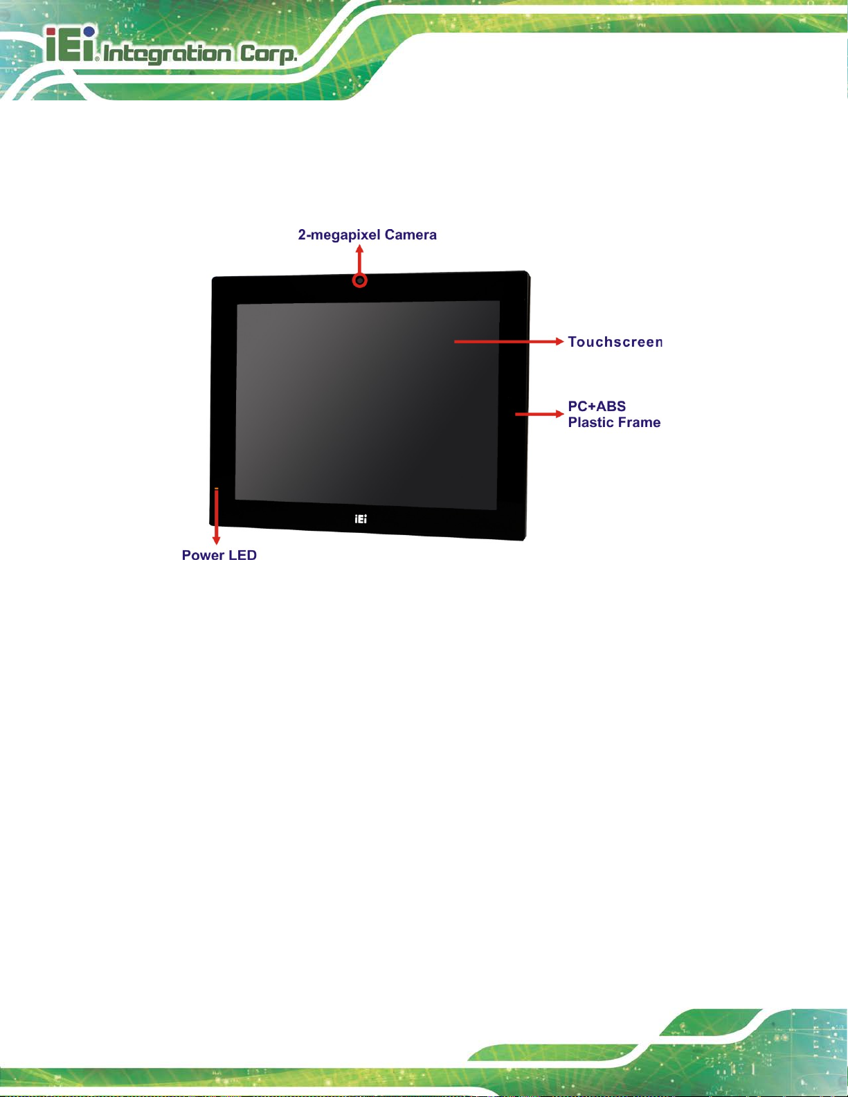
1.4 Front Panel
The front side of the AFL3-12C-ULT3 is a flat-bezel panel with a TFT LCD screen
surrounded by a PC/ABS plastic frame (Figure 1-2).
Figure 1-2: Front View
There is a power LED indicator located on the front panel. The status descriptions of the
power LED indicator are listed below.
Off: power cord not attached or power supply failure
Solid amber: the system is connected to a power source and is ready to be
turned on.
Solid green: the system is turned on.

AFL3-12C-ULT3 Panel PC
Page 5
1.5 Bottom Panel
The bottom panel of the AFL3-12C-ULT3 has the following connectors and switches.
Figure 1-3: Bottom Panel
1.6 Rear Panel
The rear panel has two speakers and retention screw holes that support VESA mounting.
The rear panel also has several retention screw holes for installing the optional barcode
scanner and magnetic stripe card reader.
Figure 1-4: Rear View

AFL3-12C-ULT3 Panel PC
Page 6
1.7 Side Panel
The right side panel has one E-Window that supports a variety of IEI modules to provide
additional connector interface.
Figure 1-5: Side View
1.8 System Specifications
The technical specifications for the AFL3-12C-ULT3 systems are listed in Table 1-2.
Specification AFL3-12C-ULT3
LCD Size
Max. Resolution
Brightness (cd/m2)
Contrast Ratio
LCD Color
Pixel Pitch (H x V) (mm)
Viewing Angle (H-V)
Backlight MTBF
12.1" (4:3)
1024 (W) x 768 (H)
500
700:1
16.2M
0.240 x 0.240
160° / 160°
50,000 hrs
Backlight
Touchscreen
Touch Controller
LED
Projected capacitive type with USB interface ( ani t -UV)
EETI EXC 3180

AFL3-12C-ULT3 Panel PC
Page 7
CPU (SoC)
Memory
Ethernet
Audio
Storage
Internal Speaker
Camera
Wireless & Bluetooth
Intel® Core™ i5-6300U or Intel® Celeron® 3855U
One 260-pin 2133 MHz single-channel DDR4 SO-DIMM
slot preinstalled with 4 GB SDRAM (system max. 8 GB)
Two Intel® I211 PCIe GbE controllers
Realtek ALC892 HD Audio codec
One 2.5” SATA 3G b/s HDD bay
One full-size/half-size PCIe Mini slot supports mSATA
module
Two 3 W
2-megapixel with low light function and digital
microphone
One M.2 2230 M-key module supports 802.11a/b/g/n/ac
E-Window Support
RFID Reader
Card Reader
OSD Function
Construction Material
Thermal Design
VESA Mount
Mounting
Front Panel Color
Net/Gross Weight
WLAN + Bluetooth v4.0
Yes (optional)
Mifare 13.56 MHz card reader (optional)
Magnetic stripe card reader (optional)
Controlled by OSD software
PC+ABS plastic
Fanless
75 mm x 75 mm
100 mm x 100 mm
Panel, wall, rack, stand or arm mounting
Black C
3 kg / 5.03 kg
Dimensions (W x H x D) (mm)
304 x 243 x 58

AFL3-12C-ULT3 Panel PC
Page 8
Operating Temperature
Storage Temperature
Humidity
Power Supply
Power Requirement
Power Consumption
IP Level
Safety/EMC
I/O Ports and Switches
Input:
Output:
-20ºC ~ 50ºC (with air flow)
-20ºC ~ 60ºC
10% ~ 95% (non-condensing)
96 W power adapter
100 V ~ 240 V AC, 50 Hz ~ 60 Hz
12 V DC, 8 A
12 V ~ 30 V DC
72 W, 12 V @ 6 A (Intel® Core™ i5-6300U CPU with
4 GB 2133 MHz DDR4 memory)
IP 64 compliant front panel
CE, FCC, ErP 2009/125/EC
1 x RS-232/422/485 serial port (COM2, DB-9)
Table 1-2: System Specifications
1 x RS-232 serial port (COM1, RJ-45)
2 x GbE LAN (RJ-45 connector)
2 x USB 3.0 connectors
2 x USB 2.0 connectors
1 x HDMI output connector
1 x Power switch
1 x AT/ATX switch
1 x Reset button
1 x 12 V ~ 30 V DC input jack

AFL3-12C-ULT3 Panel PC
Page 9
1.9 Dimensions
The following sections list the dimension s of the AFL3-12C-ULT3.
Figure 1-6: Dimensions (mm)

AFL3-12C-ULT3 Panel PC
Page 10
Chapter
2
2 Unpacking

AFL3-12C-ULT3 Panel PC
Page 11
The front side LCD screen has a protective plastic cover stuck to the
ures the screen is protected during the
If any of the components listed in the checklist below are missing, do not
proceed with the installation. Contact the IEI reseller or vendor the
was purchased from or contact an IEI sales representative
2.1 Unpacking
To unpack the flat bezel panel PC, follow the steps below:
WARNING!
screen. Only remove the plastic cover after the flat bezel panel PC has
been properly installed. This ens
installation process.
Step 1: Carefully cut the tape sealing the box. Only cut deep enough to break the tape.
Step 2: Open the outside box.
Step 3: Carefully cut the tape sealing the box. Only cut deep enough to break the tape.
Step 4: Open the inside box.
Step 5: Lift the panel PC out of the boxes.
Step 6: Remove the peripheral parts box from the main box. Step 0:
2.2 Packing List
NOTE:
AFL3-12C-ULT3
directly by sending an email to sales@ieiworld.com.

AFL3-12C-ULT3 Panel PC
Page 12
The AFL3-12C-ULT3 flat bezel panel PC is shipped with the following components:
Quantity Item Image
1 AFL3-12C-ULT3 panel PC
1 96 W power adapter
1 Power cord
1 RJ-45 to DB-9 COM port cable
5
Screws (M4*6) for VESA mounting
5
Screws (M3*4) for HDD installation

AFL3-12C-ULT3 Panel PC
Page 13
2.3 Optional Items
The following are optional components which may be separately purchased:
Item and Part Number Image
VESA 100 wall mount kit
(P/N: AFL WK-19B)
Panel mounting kit
(P/N: AFL3PK-08A-R10)
Rack mounting kit
(P/N: AFL3RK-12A-R10)
Arm
(P/N: ARM-11-RS)
Arm
(P/N: ARM-31-RS)

AFL3-12C-ULT3 Panel PC
Page 14
Item and Part Number Image
Stand for VESA 100
(P/N: STAN D -A12-RS)
Stand for VESA 75/VESA 100
(P/N: STAN D -C12-R10)
LCD monitor stand with adjustable hinge
(P/N: VSTAN D-A12)
Magnetic card reader
(P/N: AFL3P-W10MSR-U-R10)
Barcode scanner
(P/N: AFL3-2D-R11)
If any of these items are missing or damaged, contact the distributor or sales
representative immediately.

AFL3-12C-ULT3 Panel PC
Page 15
3 Installation
Chapter
3

AFL3-12C-ULT3 Panel PC
Page 16
Failure to take ESD precautions during the maintenance of the
may result in permanent damage to the
3.1 Anti-static Precautions
WARNING:
AFL3-12C-ULT3
AFL3-12C-ULT3 and severe injury to the user.
Electrostatic discharge (ESD) can cause serious damage to electronic components,
including the AFL3-12C-ULT3. Dry climates are especially susceptible to ESD. It is
therefore critical that whenever the AFL3-12C-ULT3 is accessed internally, or any other
electrical component is handled, the following anti-static precautions are strictly adhered
to.
Wear an anti-static wristband: Wearing a simple anti-static wristband can
help to prevent ESD from damaging the board.
Self-grounding: Before handling the board, touch any grounded conducting
material. During the time the board is handled, freq uently touch any
conducting materials that are connected to the ground.
Use an anti-static pad: When configuring the AFL3-12C-ULT3, place it on an
anti-static pad. This reduces the possibility of ESD damaging the
AFL3-12C-ULT3.
Only handle the edges of the PCB: When handling the PCB, hold the PCB
by the edges.
3.2 Installation Precautions
When installing the flat bezel panel PC, please follow the precautions listed below:
Power turned off: When installing the flat bezel panel P C, make sure the
power is off. Failing to turn off the power may cause severe injury to the body
and/or damage to the system.
Certified Engineers: Only certified engineers should install and modify
onboard functionalities.

AFL3-12C-ULT3 Panel PC
Page 17
Anti-static Discharge: If a user open the rear pan el of the flat bezel panel PC ,
to configure the jumpers or plug in added peripheral devices, ground
themselves first and wear an anti-static wristband.
3.3 Installation and Configuration Steps
The following installation steps must be foll owed.
Step 1: Unpack the flat bezel panel PC.
Step 2: Install an mSATA module or an HDD.
Step 3: Connect peripheral devices to the flat bezel p anel PC.
Step 4: Mount the flat bezel panel PC. Step 0:
3.4 Removing the Back Covers
To access the AFL3-12C-ULT3 internally the plastic back cover and the internal aluminum
cover must be removed. To remove the covers, please follow the steps below.
Step 1: Remove 12 retention screws from the back cover. Two types of screw are used
for securing the plastic cover of the AFL3-12C-ULT3. Be aware of this for
reinstalling the plastic cover. See Figure 3-1 for detail.
Figure 3-1: Back Cover Retention Screws

AFL3-12C-ULT3 Panel PC
Page 18
Step 2: Lift the plastic back cover off the AFL3-12C-ULT3.
Step 3: Remove the eight retention screws from the i nternal aluminum cover. Two types
of screw are used for securing the aluminum cover. Be aware of this for
reinstalling the aluminum cover. See Figure 3-2 for detail.
Figure 3-2: Aluminum Cover Retention Screws
Step 4: Lift the aluminum cover off the AFL3-12C-ULT3. A t hermal pad is attache d under
the center of the aluminum cover. Thus, more strength is required when lifting
the aluminum cover.
3.5 mSATA Module Installation
To install a full-size mSATA module into the AFL3-12C-ULT3, please follow the steps
below:
Step 1: Remove the plastic back cover and the internal aluminum cov er. See
Section 3.4 above.
Step 2: Locate the mSATA module slot. Remove the preinstalled retention screw on the
screw pillar as shown in Figure 3-3.

AFL3-12C-ULT3 Panel PC
Page 19
Figure 3-3: mSATA Module Slot Location
Step 3: Remove the retention screw as shown in Figure 3-4.
Figure 3-4: Removing the Retention Screw and Standoff

AFL3-12C-ULT3 Panel PC
Page 20
Step 4: Line up the notch on the mSATA module with the notch on the connector. Slide
the PCIe Mini card into the socket at an angle of about 20º (Figure 3-5).
Figure 3-5: Installing an mSATA Module
Step 5: Secure the mSATA m odule with the retention screw. Push the other end of the
mSATA module down and secure the module with the previously removed
retention screw (Figure 3-5).
Figure 3-6: Securing the mSATA Module

AFL3-12C-ULT3 Panel PC
Page 21
Step 6: Re-install the aluminum cover and the plastic back cover. Step 0:
NOTE:
To install a half-size mSATA module, remove both the retention screw
and standoff of the PCIe Mini card slot, and install the standoff into the
screw hole for the half-size card. Insert the half-size mSATA module
into the socket. Then, secure the module with the previously removed
retention screw.
3.6 HDD Installation
To install the HDD into the system, plea se follow the steps below:
Step 1: Remove the plastic back cover and the internal aluminum cover. See
Section 3.4 above.
Step 2: Remove the four HDD bracket retention screws and lift the HDD bracket off the
panel PC.
Figure 3-7: HDD Bracket Retention Screws

AFL3-12C-ULT3 Panel PC
Page 22
Step 3: Attach the HDD brackets to the HDD. To do this, align the four retention screw
holes in the both sides of the HDD bracket with the retention screw holes on the
sides of the HDD. Insert four retention screws (M3*4) into the HDD bracket
(Figure 3-8).
Figure 3-8: HDD Retention Screws
Step 4: Install the HDD into the AFL3-12C-ULT3 by aligning the retention screw holes in
the HDD brackets with the retention screw holes on the chassis. Insert the four
retention screws.
Step 5: Connect the SATA cable to the rear of HDD from the motherboard.
Figure 3-9: HDD Installation

AFL3-12C-ULT3 Panel PC
Page 23
Step 6: Replace the internal aluminum cover and the plast ic back cover. Step 0:
3.7 Serial Port Configuration and Connection
The AFL3-12C-ULT3 series has two serial ports, including one RS-232 port (COM1, RJ-45)
and one RS-232/422/484 port (COM2, DB-9). The jumper settings and pinouts of the
serial ports are listed in the following secti ons.
3.7.1 RS-232 Serial Port Connection
The RS-232 port (COM1) is a RJ-45 serial device connector on the bottom panel. The
COM1 port connects to a cable with a standard D-sub 9 connector at the other end (cable
included). Follow the steps below to connect a serial device to the AFL3-12C-ULT3 panel
PC.
Step 1: Locate the RJ-45 connector. The location of the RJ-45 serial port connector is
shown in Chapter 1. The RJ-45 connector for the serial port can be identified
easily as the RJ-45 for the network has two LEDs on the port, while the
connector for the serial cable doesn’t.
Step 2: Insert the RJ-45 to D-sub 9 cable.
Step 3: Insert the serial connector. Insert the D-sub 9 connector of a serial device into
the D-sub 9 connector on the cable. See Figure 3-10.

AFL3-12C-ULT3 Panel PC
Page 24
Figure 3-10: Serial Device Connector
Step 4: Secure the connector. Secure the serial device connector to the ex ternal
interface by tightening the two retention scre ws on eit her side of t he conne ctor.
3.7.1.1 RS-232 Serial Port Pinouts
The pinouts of the RS-232 serial port (COM1) are listed in the following table.
Pin No. Description Pin No. Description
1 DCD 2 RXD
3 TXD 4 DTR
5 GND 6 DSR
7 RTS 8 CTS
9 RI
Table 3-1: RS-232 Serial Port (COM1) Pinouts
3.7.2 RS-232/422/485 Serial Port Connection
Step 0:
The bottom panel of the AFL3-12C-ULT3 has one D-sub 9 male connector (COM2) for
RS-232/422/485 connection. The serial communication mode selection can be made
through the BIOS options. Please refer to Section 4.3.2.1.2 for detail information. The
pinouts of the D-sub 9 connector are listed below.

AFL3-12C-ULT3 Panel PC
Page 25
PIN NO. RS-232 RS-422 RS-485
1 DCD TXD422- TXD4852 SIN TXD422+ TXD485+
3 SOUT RXD422+ -4 DTR RXD422- -5 GND -- -6 DSR -- -7 RTS -- -8 CTS -- -9 RI -- --
Table 3-2: RS-232/422/485 Serial Port (COM2) Pinouts
3.8 AT/ATX Mode Selection
AT or ATX power mode can be used on the AFL3-12C-ULT3. The selection is made
through an AT/ATX switch located on the bottom panel (Figure 3-11).
Figure 3-11: AT/ATX Switch Location
3.8.1 AT Power Mode
With the AT mode selected, the power is controlled by a central power unit rather than a
power switch. The AFL3-12C-ULT3 panel PC turns on automatically when the power is
connected. The AT mode benefits a production line to control multiple panel PCs from a
central management center and other applications including:
ATM
Self-service kiosk
Plant environment monitoring system
Factory automation platform

AFL3-12C-ULT3 Panel PC
Page 26
Manufacturing shop flow
3.8.2 ATX Power Mode
With the ATX mode selected, the AFL3-12C-ULT3 panel PC goes in a standby mode
when it is turned off. The panel PC can be easily turned on via network or a power switch
in standby mode. Remote power control is perfect for advertising applications since the
broadcasting time for each panel PC can be set individually and controlled rem otely. Other
possible application includes
Security surveillance
Point-of-Sale (POS)
Advertising terminal
3.9 Mounting the System
The methods of mounting the AFL3-12C-ULT3 are listed below.
Wall mounting
Panel mounting
Rack mounting
Arm mounting
Stand mounting
The mounting methods are described below.
3.9.1 Wall Mounting
To mount the flat bezel panel PC onto the wall, pleas e follow the steps below.
Step 1: Select the location on the wall for the wall-mounting bra cket .
Step 2: Carefully mark the locations of the four screw holes in the bracket on the wall.
Step 3: Drill four pilot holes at the marked locations on the wall for the bracket retention
screws.
Step 4: Align the wall-mounting bracket screw holes wit h the pilot holes.

AFL3-12C-ULT3 Panel PC
Page 27
Step 5: Secure the mounting-bracket to the wall by inserting the retention screws into
the four pilot holes and tightening them (Figure 3-12).
Figure 3-12: Wall-mounting Bracket
Step 6: Insert the four monitor mounting screws provi ded i n the wall mount kit into the
four screw holes on the real panel of the flat bezel panel PC and ti ghten until the
screw shank is secured against the rear panel (Figure 3-13).

AFL3-12C-ULT3 Panel PC
Page 28
WARNING:
Please use the M4 screws provided in the wall mount kit for the rear panel.
If the screw is missing, the thread depth of the replacement screw should
be not more than 4 mm.
Step 7: Align the mounting screws on the monitor rear pan el with the mounting holes on
the bracket.
Step 8: Carefully insert the screws through the holes and gently pull the monitor
downwards until the monitor rests securel y in the slotted holes (Figure 3-13).
Ensure that all four of the mounting screw s fit snugly into their respective slotted
holes.
NOTE:
In the diagram below the bracket is already install ed on the wall.

AFL3-12C-ULT3 Panel PC
Page 29
Figure 3-13: Chassis Support Screws
Step 9: Secure the panel PC by fastening the retention s crew of the wall-mounting
bracket (Figure 3-14).
Figure 3-14: Secure the Panel PC

AFL3-12C-ULT3 Panel PC
Page 30
3.9.2 Panel Mounting
To mount the AFL3-12C-ULT3 flat bezel panel PC into a panel, please follow the steps
below.
Step 1: Select the position on the panel to mount the panel PC.
Step 2: Cut out a section corresponding to the size shown below. T he size must be
smaller than the outer edge.
Figure 3-15: Cutout Dimensions
Step 3: Slide the panel PC through the hole until the frame is flush against the panel.
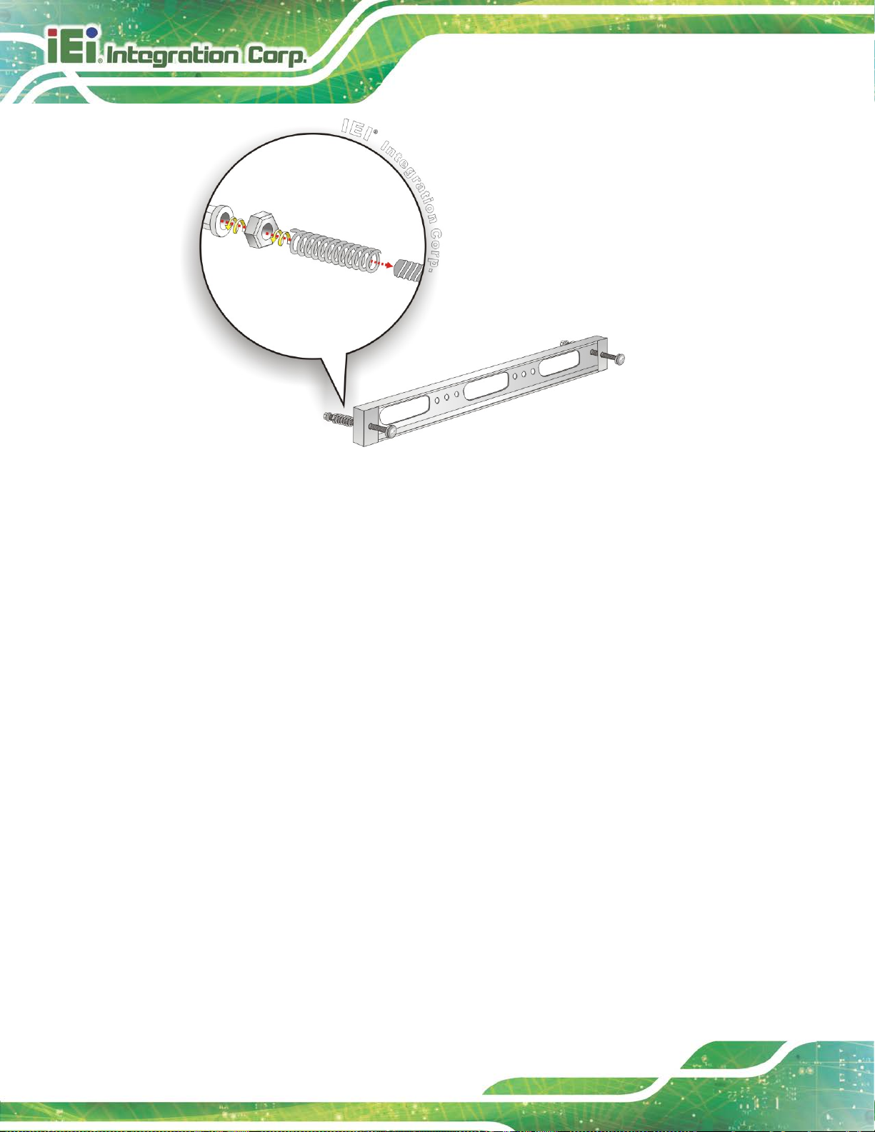
Step 4: Insert a M5*50 screw into the screw hole on the sid e of the panel mounting
bracket. Then, install the following components onto the screw in sequence.
See Figure 3-16.
Sequence Item Photo Instruction
1 Spring
2 Nut
3 Plastic
cap
Install a spring onto the screw.
Tighten a nut until the spring is
compressed enough for plastic cap.
Tighten a plastic cap onto the end of
screw thread.

AFL3-12C-ULT3 Panel PC
Page 31
Step 5: Repeat Step 4 to install the other three screws into the sides of the two panel
mounting brackets.
Figure 3-16: Panel Mounting Kit Installation
Step 6: Align the panel mounting bracket screw holes with the VESA mounti ng hol es on
the rear of the panel PC.
Step 7: Secure the two panel mounting brackets to the rear of the panel PC by inserting
the four retention screws into the VESA mounting holes and tightening them
(Figure 3-17).Step 0:

AFL3-12C-ULT3 Panel PC
Page 32
Figure 3-17: Securing Panel Mounting Brackets
NOTE:
The panel mounting kit described in this section is an optional item. To
purchase it, please contact an IEI sales representative.

AFL3-12C-ULT3 Panel PC
Page 33
3.9.3 Cabinet and Rack Installation
The AFL3-12C-ULT3 flat bezel panel PC can be installed into a cabinet or rack. The
installation procedures are similar to the panel mounting installation. To do this, please
follow the steps below:
NOTE:
When purchasing the cabinet/rack installation bracket, make sure it is
compatible with both the AFL3-12C-ULT3 flat bezel panel PC and the
rack/cabinet into which the AFL3-12C-ULT3 is installed.
Step 1: Slide the rear chassis of the AFL3-12C-ULT3 panel PC through the rack/cabinet
bracket until the frame is flush against the front of the bracket.
Step 2: Insert a M5*50 screw into the screw hole on the sid e of the rack mounting
bracket. Then, install the following components onto the screw in sequence.
See Figure 3-16.
Sequence Item Photo Instruction
1 Spring
2 Nut
3 Plastic
cap
Install a spring onto the screw.
Tighten a nut until the spring is
compressed enough for plastic cap.
Tighten a plastic cap onto the end of
screw thread.
Step 3: Repeat Step 4 to install the other three screws into the sides of the two rack
mounting brackets.
AFL3-12C-ULT3 Panel PC
Page 34
Figure 3-18: Rack Mounting Kit Installation
Step 4: Align the rack mounting bracket screw holes with the VESA mounting holes on
the rear of the panel PC.
Step 5: Secure the two rack mounting brackets to the rear of t he panel PC by inserting
the four retention screws into the VESA mounting holes and tightening them
(Figure 3-19).

AFL3-12C-ULT3 Panel PC
Page 35
Figure 3-19: Securing Rack Mounting Brackets
Step 6: Slide the panel PC with the attached rack/cabinet bracket into a rack or cabinet
(Figure 3-20).
Figure 3-20: Install into a Rack/Cabinet

AFL3-12C-ULT3 Panel PC
Page 36
Step 7: Once the panel PC with the attached rack/cabinet bracket has been properly
inserted into the rack or cabinet, secure the f ront of the rack/cabinet bracket to
the front of the rack or cabinet (Figure 3-20).
NOTE:
The rack mounting kit described in this section is an optional item. To
purchase it, please contact an IEI sales representative.
3.9.4 Arm Mounting
The AFL3-12C-ULT3 is VESA (Video Electronics Standards Association) compliant and
can be mounted on an arm with a 75 mm or a 100 mm interface pad. To mount the
AFL3-12C-ULT3 on an arm, please follow the steps below.
Step 1: The arm is a separately purchased item. P l ease correctly mount the arm onto
the surface it uses as a base. To do this, refer to the installation documentation
that came with the mounting arm.
NOTE:
When purchasing the arm please ensure that it is VESA compliant and that
the arm has a 75 mm or a 100 mm interfa ce pa d. I f t he mount ing arm is not
VESA compliant it cannot be used to su pport the AFL3-12C-ULT3 flat bezel
panel PC.
Step 2: Once the mounting arm has been firmly attached to the surface, lift the f lat bezel
panel PC onto the interface pad of the mounting arm .
Step 3: Align the retention screw holes on the mounting a rm interface with those in the
flat bezel panel PC (Figure 3-21).

AFL3-12C-ULT3 Panel PC
Page 37
Figure 3-21: Arm Mounting Retention Screw Holes
Step 4: Secure the AFL3-12C-ULT3 to the interface pad by inserting four retention
screws through the mounting arm interface pad and into the AFL3-12C-ULT3.Step 0:
Figure 3-22: Arm Mounting

AFL3-12C-ULT3 Panel PC
Page 38
3.9.5 Stand Mounting
To mount the AFL3-12C-ULT3 using the stand mounting kit, please follow the steps
below.
Step 1: Locate the screw holes on the rear of the AFL3-12C-ULT3. This is where the
bracket will be attached.
Step 2: Align the bracket with the screw holes.
Step 3: To secure the bracket to the AFL3-12C-ULT3 insert the retention screws into the
screw holes and tighten them.
Figure 3-23: Stand Mounting (Stand-A/Bxx)

AFL3-12C-ULT3 Panel PC
Page 39
3.10 Powering On the System
To power on the system, follow the steps below:
Step 1: Connect the power cord to the power adapter. Connect the other end of the
power cord to a power source.
Step 2: Connect the power adapter to the power connect or of the AFL3-12C-ULT3.
Step 3: Locate the power button on the I/O panel.
Step 4: ATX mode (default): long press the power button for 3~5 seconds to power up
the system. Once powered up, the power LED on t he front panel turns on in
green.
AT mode: the system turns on automatically.
Figure 3-24: Powering On the System

AFL3-12C-ULT3 Panel PC
Page 40
outlet with earthing
WARNING!
Ensure to connect the power cord to a socketconnection.
3.11 Reset the System
The reset button enables user to reboot the system when the system is turned on. The
reset button location is shown in Figure 3-25. Press the reset butt on to reboot the system.
Figure 3-25: Reset Button Location

AFL3-12C-ULT3 Panel PC
Page 41
3.12 Software Installation
All the drivers for the AFL3-12C-ULT3 are available on IEI Resource Download Center
(https://download.ieiworld.com
relevant software, utilities, and documentation.
). Type AFL3-12C-ULT3 and press Enter to find all the
Figure 3-26: IEI Resource Download Center
IEI provides the following drivers for Windows 7, Windows 8 and Windows 10 operating
systems.
Chipset
VGA (Windows 64-bit OS only)
LAN (Windows 64-bit OS only)
Audio
Intel
ME (Intel
Wi-Fi
Touchscreen
RFID (for optional RFID module)
®
Serial IO (Windows 8.1/10 64-bit OS only)
®
AMT)

AFL3-12C-ULT3 Panel PC
Page 42
3.13 Driver Download
To download drivers from IEI Resource Download Center, follow the steps below.
Step 1: Go to https://download.ieiworld.com
AFL3-12C-ULT3AFL3-12C-ULT3AFL3-12C-ULT3 and press Enter.
Step 2: All product-related software, utilities, and documentation will be listed. You can
choose Driver to filter the result.
. Type
Step 3: Click the driver file name on the page and you will be prompted with the
following window. You can download the ent i re ISO file (
arrow to find an individual driver and click the file name to download (
), or click the small
).

AFL3-12C-ULT3 Panel PC
Page 43
NOTE:
To install software from the downloaded ISO image file in Windows 8,
8.1 or 10, double-click the ISO file to mount it as a virtual drive to view
its content. On Windows 7 system, an additional tool (such as Virtual
CD-ROM Control Panel from Microsoft) is needed to mount the file.
3.14 Installing Windows 7 from USB 3.0 Drives
Microsoft Windows 7 installation media does not include nat ive driver support for USB 3.0,
so during installation, a keyboard/mouse connected to a USB 3.0 port does not respond.
The Windows 7 USB 3.0 Creator Utility automates the steps to update a Windows 7
installation image so that it contains USB 3.0 drivers. To install Windows 7 from a USB
drive onto the AFL3-12C-ULT3, please follow the steps described below.
Step 1: Create a USB flash drive installer. Use your Windows 7 DVD or ISO image to
create a bootable USB flash drive. Instruction s on how to do are found on
Microsoft’s website
.

AFL3-12C-ULT3 Panel PC
Page 44
Step 2: Download and unzip the Windo ws 7 USB 3. 0 Creator ut ility to a temporary folder
on the Admin system.
Step 3: Connect the USB device containing the Windows 7 image to the Admin system.
Step 4: Right-click the file “Installer_Creator.exe” and select Run as administrator.
Step 5: Browse to the root of the USB drive.
Step 6: Click “Create Image” to begin the creation process.
Step 7: Wait for the process t o finish. It can take up to 15 minutes.
Step 8: Using the updated installer, proceed with the Windows 7 install ation as you
normally would.

AFL3-12C-ULT3 Panel PC
Page 45
Chapter
4
4 BIOS Setup

AFL3-12C-ULT3 Panel PC
Page 46
Some of the BIOS options may vary throughout the life cycle of the
4.1 Introduction
The BIOS is programmed onto the BIOS chip. The BIOS setup p rogram allow s changes t o
certain system settings. This chapter outli nes t he options that can be changed.
NOTE:
product and are subject to change without prior notice .
4.1.1 Starting Setup
The UEFI BIOS is activated when the computer is turned on. The setup program can be
activated in one of two ways.
1. Press the D
2. Press the D
appears on the screen. 0.
If the message disappears before the D
and try again.
ELETE or F2 key as soon as the system is turned on or
ELETE or F2 key when the “Press Del to enter SETUP” message
ELETE or F2 key is pressed, restart the computer
4.1.2 Using Setup
Use the arrow keys to highlight items, press ENTER to select, use the PageUp and
PageDown keys to change entries, press F1 for help and press E
keys are shown in.
Key Function
Up arrow Move to previous item
Down arrow Move to next item
Left arrow Move to the item on the left hand side
SC to quit. Navigation
Right arrow Move to the item on the right hand side
+ Increase the numeric value or make changes

AFL3-12C-ULT3 Panel PC
Page 47
Key Function
- Decrease the numeric value or make change s
F1 key General help, only for Status Page Setup Menu and Option
F2 key Load previous values.
F3 key Load optimized defaults
F4 key Save changes and Exit BIOS
Esc key Main Menu – Quit and not save changes into CMOS
4.1.3 Getting Help
Page Setup Menu
Status Page Setup Menu and Option Page Setup Menu -Exit current page and return to Main Menu
When F1 is pressed a small help window describing the appropriate keys to use and the
possible selections for the highlighted item appears. To ex it the Help Window press E
the F1 key again.
4.1.4 BIOS Menu Bar
The menu bar on top of the BIOS screen has the foll owing main items:
Main – Changes the basic system configuration.
Advanced – Changes the advanced system settings.
Chipset – Changes the chipset settings.
Security – Sets User and Supervisor Passwords.
Boot – Changes the system boot configuration.
Save & Exit – Selects exit options and loads default settings
The following sections completely describe the configuration options found in the menu
SC or
items at the top of the BIOS screen and listed above.

AFL3-12C-ULT3 Panel PC
Page 48
Aptio Setup Utility – Copyright (C) 2018 American Megatrends, Inc.
Main
Advanced
Chipset
Security
Boot
Save & Exit
BIOS Information
System Time [00:18:35]
Version 2.17.1255. Copyright (C) 2018 American Megatrends, Inc.
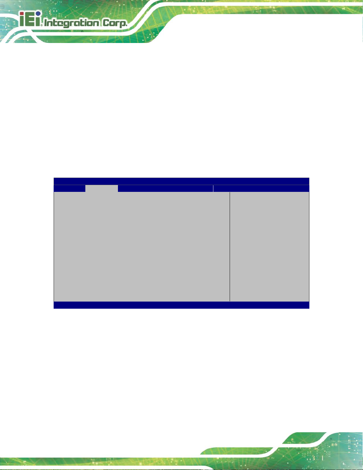
4.2 Main
The Main BIOS menu (BIOS Menu 1) appears when the BIOS Setup program is entered.
BIOS Vendor American Megatrends
Core Version 5.11
Compliency UEFI 2.4; PI 1.3
Project Version Z455AR12.ROM
Build Date and Time 04/27/2018 12:13:49
iWDD Vender iEi
iWDD Version Z455ER10.bin
Processor Information
Name SkyLake
Brand String Intel(R) Core(TM)
i5-6300U CPU @ 2.40GHz
Frequency 2300 MHz
Processor ID 406E3
Stepping D0/K0
Number of Processors 2Core(s) / 4Thread(s)
Microcode Revision C2
GT Info GT2
IGFX VBIOS Version 1040
Memory RC Version 1.9.0.0
Total Memory 4096 MB
Memory Frequency 2133 MHz
PCH Information
Name SKL PCH-LP
PCH SKU PCH-LP Mobile (U)
Stepping 21/C1
LAN PHY Revision N/A
ME FW Version 11.8.50.3434
ME Firmware SKU Corporate SKU
SPI Clock Frequency
D0FR Support Unsupported
Read Status Clock Frequency 17 MHz
Write Status Clock Frequency 17 MHz
Fast Read Status Clock Frequency 17 MHz
System Date [Fri 01/01/2010]
Premium SKU
Set the Date. Use Tab to
switch between Data
elements.
---------------------
: Select Screen
↑ ↓: Select Item
Enter Select
+/-: Change Opt.
F1: General Help
F2: Previous Values
F3: Optimized Defaults
F4: Save & Exit
ESC: Exit
BIOS Menu 1: Main

AFL3-12C-ULT3 Panel PC
Page 49
Aptio Setup Utility – Copyright (C) 2018 American Megatrends, Inc.
Main
Advanced
Chipset
Security
Boot
Save & Exit
Version 2.17.1255. Copyright (C) 2018 American Megatrends, Inc.
The System Overview field also has two user configurable fields:
System Date [xx/xx/xx]
Use the System Date option to set the system date. Manually enter the day, month and
year.
System Time [xx :xx:xx]
Use the System Time option to set the system time. Manually enter the hours, minutes
and seconds.
4.3 Advanced
Use the Advanced menu (BIOS Menu 2) to configure the CPU and peripheral devices
through the following sub-menus:
WARNING!
Setting the wrong values in the sections below may cause the system
to malfunction. Make sure that the settings made are compatible with
the hardware.
> ACPI Settings
> Super IO Configuration
> Hardware Monitor
> iWDD H/W Monitor
> RTC Wake Settings
> Serial Port Console Redirection
> CPU Configuration
> SATA Configuration
> USB Configuration
> iEi Feature
System ACPI Parameters.
----------------------
: Select Screen
↑ ↓: Select Item
Enter Select
F1 General Help
F2 Previous Values
F3 Optimized Defaults
F4 Save
ESC Exit
BIOS Menu 2: Advanced

AFL3-12C-ULT3 Panel PC
Page 50
Aptio Setup Utility – Copyright (C) 2018 American Megatrends, Inc.
Advanced
Select the highest ACPI
ESC: Exit
Version 2.17.1255. Copyright (C) 2018 American Megatrends, Inc.
S3 (Suspend to
off. Power to the RAM is maintained. The
computer returns slower to a working state, but
4.3.1 ACPI Settings
The ACPI Settings menu (BIOS Menu 3) configures the Advanced Configuration and
Power Interface (ACPI) options.
ACPI Settings
ACPI Sleep State [S3 (Suspend to RAM]
sleep state the system
will enter when the
SUSPEND button is
pressed.
----------------------
: Select Screen
↑ ↓: Select Item
Enter Select
+/-: Change Opt.
F1: General Help
F2: Previous Values
F3: Optimized Defaults
F4: Save & Exit
ACPI Sleep State [S3 (Suspend to RAM)]
Use the ACPI Sleep State option to specify the sleep state the system enters when it is
not being used.
BIOS Menu 3: ACPI Settings
RAM)
DEFAULT
The caches are flushed and the CPU is powered
more power is saved.

AFL3-12C-ULT3 Panel PC
Page 51
Aptio Setup Utility – Copyright (C) 2018 American Megatrends, Inc.
Advanced
Version 2.17.1255. Copyright (C) 2018 American Megatrends, Inc.
Aptio Setup Utility – Copyright (C) 2018 American Megatrends, Inc.
Advanced
ESC Exit
Version 2.17.1255. Copyright (C) 2018 American Megatrends, Inc.
4.3.2 Super IO Configuration
Use the Super IO Configuration menu (BIOS Menu 4) to set or change the
configurations for the serial ports.
F81866 Super IO Configuration
Super IO Chip F81866
> Serial Port 1 Configuration
> Serial Port 2 Configuration
BIOS Menu 4: Super IO Configuration
4.3.2.1 Serial Port n Configuration
Use the Serial Port n Configuration menu (BIOS Menu 5) to configure the serial port n.
Set Parameters of Serial
Port 1 (COMA)
---------------------
: Select Screen
↑ ↓: Select Item
Enter Select
F1 General Help
F2 Previous Values
F3 Optimized
Defaults
F4 Save
ESC Exit
Serial Port 1 Configuration
Serial Port [Enabled]
Device Settings IO=3F8h; IRQ=4
Change Settings [Auto]
BIOS Menu 5: Serial Port n Configuration
Enable or Disable Serial
Port (COM)
---------------------
: Select Screen
↑ ↓: Select Item
Enter Select
F1 General Help
F2 Previous Values
F3 Optimized
Defaults
F4 Save

AFL3-12C-ULT3 Panel PC
Page 52
IO=3F8h; IRQ=3,
IO=2F8h; IRQ=3,
8h; IRQ=3,
8h; IRQ=3,
4.3.2.1.1 Serial Port 1 Configuration
Serial Port [Enabled]
Use the Serial Port option to enable or disable the serial port.
Disabled
Enabled DEFAULT
Change Settings [Auto]
Use the Change Settings option to change the serial port IO port address and interrupt
address.
Auto DEFAULT
IO=3F8h; IRQ=4
4,5,6,7,9,10,11,12
4,5,6,7,9,10,11,12
Disable the serial port
Enable the serial port
The serial port IO port address and int errupt
address are automatically detected.
Serial Port I/O port address is 3F8h and the
interrupt address is IRQ4
Serial Port I/O port address is 3F8h and the
interrupt address is IRQ3,4,5,6,7,9,10,11,12
Serial Port I/O port address is 2F8h and the
interrupt address is IRQ3,4,5,6,7,9,10,11,12
IO=3E
4,5,6,7,9,10,11,12
IO=2E
4,5,6,7,9,10,11,12
Serial Port I/O port address is 3E8h and the
interrupt address is IRQ3,4,5,6,7,9,10,11,12
Serial Port I/O port address is 2E8h and the
interrupt address is IRQ3,4,5,6,7,9,10,11,12

AFL3-12C-ULT3 Panel PC
Page 53
IO=3F8h; IRQ=3,
IO=2F8h; IRQ=3,
8h; IRQ=3,
8h; IRQ=3,
4.3.2.1.2 Serial Port 2 Configuration
Serial Port [Enabled]
Use the Serial Port option to enable or disable the serial port.
Disabled
Enabled DEFAULT
Change Settings [Auto]
Use the Change Settings option to change the serial port IO port address and interrupt
address.
Auto DEFAULT
IO=2F8h; IRQ=3
4,5,6,7,9,10,11,12
4,5,6,7,9,10,11,12
Disable the serial port
Enable the serial port
The serial port IO port address and int errupt
address are automatically detected.
Serial Port I/O port address is 2F8h and the
interrupt address is IRQ3
Serial Port I/O port address is 3F8h and the
interrupt address is IRQ3,4,5,6,7,9,10,11,12
Serial Port I/O port address is 2F8h and the
interrupt address is IRQ3,4,5,6,7,9,10,11,12
IO=3E
4,5,6,7,9,10,11,12
IO=2E
4,5,6,7,9,10,11,12
Serial Port I/O port address is 3E8h and the
interrupt address is IRQ3,4,5,6,7,9,10,11,12
Serial Port I/O port address is 2E8h and the
interrupt address is IRQ3,4,5,6,7,9,10,11,12
AFL3-12C-ULT3 Panel PC
Page 54
Aptio Setup Utility – Copyright (C) 2018 American Megatrends, Inc.
Advanced
ESC Exit
Version 2.17.1255. Copyright (C) 2018 American Megatrends, Inc.
Transfer Mode [RS232]
Use the Transfer Mode option to select the Serial Port 3 signaling mode.
RS422
RS232 DEFAULT
RS485
4.3.1 Hardware Monitor
The Hardware Monitor menu (BIOS Menu 6) displays system temperature.
PC Health Status
System temperature :+39 °C
Serial Port 3 signaling mode is RS-422
Serial Port 3 signaling mode is RS-232
Serial Port 3 signaling mode is RS-485
---------------------
: Select Screen
↑ ↓: Select Item
Enter Select
+ - Change Opt.
F1 General Help
F2 Previous Values
F3 Optimized Defaults
F4 Save & Exit
BIOS Menu 6: Hardware Monitor

AFL3-12C-ULT3 Panel PC
Page 55
Aptio Setup Utility – Copyright (C) 2018 American Megatrends, Inc.
Advanced
ESC Exit
Version 2.17.1255. Copyright (C) 2018 American Megatrends, Inc.
4.3.2 iWDD H/W Monitor
The iWDD H/W Monitor menu (BIOS Menu 7) displays CPU temperature and system
voltages.
PC Health Status
CPU temperature :+34 °C
CPU_CORE :+0.897 V
+5V :+5.023 V
+12V :+12.064 V
+DDR : +1.199 V
+5VSB :+5.038 V
+3.3V :+3.271 V
+3.3VSB :+3.097 V
BIOS Menu 7: iWDD H/W Monitor
---------------------
: Select Screen
↑ ↓: Select Item
Enter Select
+ - Change Opt.
F1 General Help
F2 Previous Values
F3 Optimized Defaults
F4 Save & Exit

AFL3-12C-ULT3 Panel PC
Page 56
Aptio Setup Utility – Copyright (C) 2018 American Megatrends, Inc.
Advanced
ESC Exit
Version 2.17.1255. Copyright (C) 2018 American Megatrends, Inc.
The real time clock (RTC) cannot generate a wake
every day at the specified time. Besides, the
following options appear with values that can be
4.3.3 RTC Wake Settings
The RTC Wake Settings menu (BIOS Menu 8) conf igure s RTC wake event .
Wake system with Fixed Time [Disabled]
BIOS Menu 8: RTC Wake Settings
Wake system with Fixed Time [Disabled]
Use the Wake system with Fixed Time option to enable or disable the system wake on
Enable or disable System
wake on alarm event. When
enabled, System will
wake on the
date::hr::min::sec
specified
----------------------
: Select Screen
↑ ↓: Select Item
Enter Select
F1 General Help
F2 Previous Values
F3 Optimized Defaults
F4 Save
alarm event.
Disabled D
Enabled
EFAULT
event
If selected, the Wake up every day option appears
allowing you to enable to disable the sy st em t o wake
selected:
Wake up date
Wake up hour
Wake up minute

AFL3-12C-ULT3 Panel PC
Page 57
Aptio Setup Utility – Copyright (C) 2018 American Megatrends, Inc.
Advanced
ESC Exit
Version 2.17.1255. Copyright (C) 2018 American Megatrends, Inc.
4.3.4 Serial Port Console Redirection
The Serial Port Console Redirection menu (BIOS Menu 9) allows the console
redirection options to be configured. Console redirection allows users to maintain a
system remotely by re-directing keyboard input and text output through the serial port.
Wake up second
After setting the alarm, the computer turns itself on
from a suspend state when the alarm goes off.
COM1
Console Redirection [Disabled]
> Console Redirection Settings
COM2
Console Redirection [Disabled]
> Console Redirection Settings
Legacy Console Redirection
> Legacy Console Redirection Settings
BIOS Menu 9: Serial Port Console Redirection
Console Redirection [Disabled]
Console Redirection
Enable or Disable
---------------------
: Select Screen
↑ ↓: Select Item
Enter Select
F1 General Help
F2 Previous Values
F3 Optimized
Defaults
F4 Save
Use Console Redirection option to enable or disable the con sole redirection function.
Disabled DEFAULT
Enabled
Disabled the console redirection function
Enabled the console redirection function

AFL3-12C-ULT3 Panel PC
Page 58
Aptio Setup Utility – Copyright (C) 2018 American Megatrends, Inc.
Advanced
Version 2.17.1255. Copyright (C) 2018 American Megatrends, Inc.
4.3.4.1 Legacy Console Redirection Settings
The Legacy Console Redirection Settings menu (BIOS Menu 10) allows the legacy
console redirection options to be configured.
Legacy Serial Redirection Port [COM1]
BIOS Menu 10: Legacy Console Redirection Settings
Legacy Serial Redirection Port [COM1]
Use the Legacy Serial Redirection Port option to specify a COM port to display
redirection of legacy OS and legacy OPROM mes sages. The options include:
Select a COM port to
display redirection of
Legacy OS and Legacy
OPROM Messages
---------------------
: Select Screen
↑ ↓: Select Item
Enter Select
F1 General Help
F2 Previous Values
F3 Optimized
Defaults
F4 Save
ESC Exit
COM1 D
COM2
EFAULT

AFL3-12C-ULT3 Panel PC
Page 59
Aptio Setup Utility – Copyright (C) 2018 American Megatrends, Inc.
Advanced
function
Unicode chars onto 1 or
Version 2.17.1255. Copyright (C) 2018 American Megatrends, Inc.
4.3.4.2 Console Redirection Settings
The Console Redirection Settings me nu (BIOS Menu 11) allows the console redire ction
options to be configured. The option is activ e when Console Redirection option is enabled.
COM1
Console Redirection Settings
Terminal Type [ANSI]
Bits per second [115200]
Data Bits [8]
Parity [None]
Stop Bits [1]
BIOS Menu 11: Console Redirection Settings
Emulation: ANSI:
Extended ASCII char set.
VT100: ASCII char set.
VT100+: Extends VT100 to
support color,
keys, etc. VT-UTF8: Uses
UTF8 encoding to map
more bytes.
---------------------
: Select Screen
↑ ↓: Select Item
Enter Select
F1 General Help
F2 Previous Values
F3 Optimized
Defaults
F4 Save
ESC Exit
Terminal Type [ANSI]
Use the Terminal Type option to specify the remote termi nal type.
VT100
VT100+
VT-UTF8
ANSI DEFAULT
The target terminal type is VT100
The target terminal type is VT100+
The target terminal type is VT-UTF8
The target terminal type is ANSI

AFL3-12C-ULT3 Panel PC
Page 60
The parity bit is always 1. This option does not
The parity bit is always 0. This option does not
Bits per second [115200]
Use the Bits per second option to specify the serial port transmission speed. The speed
must match the other side. Long or noisy lines may require lower speeds.
9600
19200
57600
115200 DEFAULT
Data Bits [8]
Use the Data Bits option to specify the number of data bits.
7
8 DEFAULT
Parity [None]
Use the Parity option to specify the parity bit that can be sent with the data bits for
detecting the transmission errors.
Sets the serial port transmission speed at 9600.
Sets the serial port transmission speed at 19200.
Sets the serial port transmission speed at 57600.
Sets the serial port transmission speed at 115200.
Sets the data bits at 7.
Sets the data bits at 8.
None DEFAULT
Even
Odd
Mark
Space
No parity bit is sent with the data bits.
The parity bit is 0 if the number of ones in the data
bits is even.
The parity bit is 0 if the number of ones in the data
bits is odd.
provide error detection.
provide error detection.

AFL3-12C-ULT3 Panel PC
Page 61
Aptio Setup Utility – Copyright (C) 2018 American Megatrends, Inc.
Advanced
and Linux (OS optimized
ESC Exit
Version 2.17.1255. Copyright (C) 2018 American Megatrends, Inc.
Stop Bits [1]
Use the Stop Bits option to specify the number of stop bits used to indicate the end of a
serial data packet. Communication with slow devices may require more than 1 stop bit.
4.3.5 CPU Configuration
Use the CPU Configuration menu (BIOS Menu 12) to view detailed CPU specifications
and configure the CPU.
CPU Configuration
Intel(R) Core(TM) i5-6300U CPU @ 2.40GHz
CPU Signature 406E3
Microcode Patch C2
Max CPU Speed 2400 MHz
Min CPU Speed 400 MHz
CPU Speed 2300 MHz
Processor Cores 2
Hyper Threading Technology Supported
Intel VT-x Technology Supported
Intel SMX Technology Supported
64-bit Supported
EIST Technology Supported
L1 Data Cache 32 KB x 2
L1 Code Cache 32 KB x 2
L2 Cache 256 KB x 2
L3 Cache 3 MB
Hyper-Threading [Enabled]
Active Processor Cores [All]
Intel Virtualization Technology [Disabled]
Intel(R) SpeedStep(tm) [Enabled]
CPU C states [Disabled]
1 DEFAULT
2
Sets the number of stop bits at 1.
Sets the number of stop bits at 2.
Enabled for Windows XP
for Hyper-Threading
Technology) and Disabled
for other OS (OS not
optimized for
Hyper-Threading
Technology). When
Disabled only one thread
per enabled core is
enabled.
----------------------
: Select Screen
↑ ↓: Select Item
Enter Select
F1 General Help
F2 Previous Values
F3 Optimized
Defaults
F4 Save
BIOS Menu 12: CPU Configuration

AFL3-12C-ULT3 Panel PC
Page 62
Hyper Threading Function [Enabled]
Use the Hyper Threading function to enable or disable the CPU hyper threading function.
Disabled
Enabled DEFAULT
Disables the use of hyper threading technology
Enables the use of hyper threading technology
Active Processor Cores [All]
Use the Active Processor Cores BIOS option to enable numbers of cores in the
processor package.
All DEFAULT
1
®
Intel
Use the Intel
Virtualization Technology [Disabled]
®
Virtualization Technology option to enable or disable virtualizat ion on the
system. When combined with third party software, Intel
Enable all cores in the processor package.
Enable one core in the processor package.
®
Virtualization technology allows
several OSs to run on the same system at the same time.
Intel
®
Use the Intel
Technology.
Disabled DEFAULT
Enabled
SpeedStep™ [Enabled]
®
SpeedStep™ option to enable or disable the Intel® SpeedStep
Disabled
Enabled DEFAULT
Disables Intel
Enables Intel
®
Virtualization Technology.
®
Virtualization Technology.
Disables the Intel
Enables the Intel
®
SpeedStep Technology.
®
SpeedStep Technology.

AFL3-12C-ULT3 Panel PC
Page 63
Aptio Setup Utility – Copyright (C) 2018 American Megatrends, Inc.
Advanced
ESC Exit
Version 2.17.1255. Copyright (C) 2018 American Megatrends, Inc.
CPU C State [Disabled]
Use the CPU C State option to enable or disable CPU C state.
Disabled DEFAULT
Enabled
Disables CPU C state.
Enables CPU C state.
4.3.6 SATA Configuration
Use the SATA Configuration menu (BIOS Menu 13) to change and/or set the
configuration of the SATA devices installed in the system.
STAT Controller(s) [Enabled]
SATA Mode Selection [AHCI]
SATA1 Empty
Hot Plug [Disabled]
mSATA(M_PCIE1) Empty
Enable or disable SATA
Device
---------------------
: Select Screen
↑ ↓: Select Item
Enter Select
F1 General Help
F2 Previous Values
F3 Optimized
Defaults
F4 Save
BIOS Menu 13: SATA Configuration
STAT Controller(s) [Enabled]
Use the STAT Controller(s) option to enable or disable t he SATA device.
Enabled DEFAULT
Disabled
Enables the SATA device.
Disables the SATA device.

AFL3-12C-ULT3 Panel PC
Page 64
Before accessing the RAID configuration utility, ensure to set the
. This is to allow the “Press <CTRL+I> to enter Configuration
Utility……” message to appear during POST. Press Ctrl+I when
SATA Mode Selection [AHCI]
Use the SATA Mode Selection option to configure SATA devices as AHCI devices.
AHCI DEFAULT
RAID
NOTE:
Option ROM Messages BIOS option in the Boot menu to Force
BIOS
prompted to enter the RAID configuration utility.
Hot Plug [Disabled]
Use the Hot Plug option to enable or disable the SATA device hot plug.
Configures SATA devices as AHCI device.
Configures SATA devices as RAID device.
Disabled DEFAULT
Enabled
Disables the SATA device hot plug.
Enables the SATA device hot plug

AFL3-12C-ULT3 Panel PC
Page 65
Aptio Setup Utility – Copyright (C) 2018 American Megatrends, Inc.
Advanced
disables legacy support
ESC Exit
Version 2.17.1255. Copyright (C) 2018 American Megatrends, Inc.
4.3.7 USB Configuration
Use the USB Configuration menu (BIOS Menu 14) to read USB configuration
information and configure the USB settin gs.
USB Configuration
USB Controllers:
1 XHCI
USB Devices:
1 Keyboard
Legacy USB Support [Enabled]
BIOS Menu 14: USB Configuration
USB Devices
Enables Legacy USB
support. AUTO option
if no USB devices are
connected. DISABLE
option will keep USB
devices available only
for EFI applications.
---------------------
: Select Screen
↑ ↓: Select Item
Enter Select
F1 General Help
F2 Previous Values
F3 Optimized
Defaults
F4 Save
The USB Devices Enabled field lists the USB devices that are enabled on the system
Legacy USB Support [Enabled]
Use the Legacy USB Support BIOS option to enable USB mouse and USB keyboard
support. Normally if this option is not e nabled, any at tached USB mouse or US B keyboa rd
does not become available until a USB comp atible operat ing syst em is fully bo oted with all
USB drivers loaded. When this option is enabled, any attached USB mouse or USB
keyboard can control the system even when there is no USB driver loaded onto the
system.

AFL3-12C-ULT3 Panel PC
Page 66
Aptio Setup Utility – Copyright (C) 2018 American Megatrends, Inc.
Advanced
crashes. Please install
service before enabling
ESC Exit
Version 2.17.1255. Copyright (C) 2018 American Megatrends, Inc.
Enabled DEFAULT
Disabled
Auto
Legacy USB support enabled
Legacy USB support disabled
Legacy USB support disabled if no USB devices are
connected
4.3.8 IEI Feature
Use the IEI Feature menu (BIOS Menu 15) to configure One Key Recovery function.
iEi Feature
Auto Recovery Function [Disabled]
Auto Recovery Function
Reboot and recover
system automatically
within 10 min, when OS
Auto Recovery API
this function
----------------------
: Select Screen
↑ ↓: Select Item
Enter Select
F1 General Help
F2 Previous Values
F3 Optimized Defaults
F4 Save
Auto Recovery Function [Disabled]
Use the Auto Recovery Function BIOS option to enable or disable the auto recovery
function of the IEI One Key Recovery.
BIOS Menu 15: IEI Feature
Disabled DEFAULT
Enabled
Auto recovery function disabled
Auto recovery function enabled

AFL3-12C-ULT3 Panel PC
Page 67
Aptio Setup Utility – Copyright (C) 2018 American Megatrends, Inc.
Main
Advanced
Chipset
Security
Boot
Save & Exit
Version 2.17.1255. Copyright (C) 2018 American Megatrends, Inc.
Aptio Setup Utility – Copyright (C) 2018 American Megatrends, Inc.
Chipset
Version 2.17.1255. Copyright (C) 2018 American Megatrends, Inc.
4.4 Chipset
Use the Chipset menu (BIOS Menu 16) to configure the system chipset.
> System Agent (SA) Configuration
> PCH-IO Configuration
BIOS Menu 16: Chipset
4.4.1 System Agent (SA) Configuration
Use the System Agent (SA) Configuration menu (BIOS Menu 17) to configure the
System Agent (SA) parameters.
System Agent (SA)
Parameters
---------------------
: Select Screen
↑ ↓: Select Item
Enter Select
+ - Change Opt.
F1 General Help
F2 Previous Values
F3 Optimized Defaults
F4 Save & Exit
ESC Exit
VT-d [Disabled]
> Graphics Configuration
> Memory Configuration
BIOS Menu 17: System Agent (SA) Configuration
VT-d capability
---------------------
: Select Screen
↑ ↓: Select Item
Enter Select
+ - Change Opt.
F1 General Help
F2 Previous Values
F3 Optimized Defaults
F4 Save & Exit
ESC Exit

AFL3-12C-ULT3 Panel PC
Page 68
Aptio Setup Utility – Copyright (C) 2018 American Megatrends, Inc.
Chipset
Graphics Memory Size used
ESC Exit
Version 2.17.1255. Copyright (C) 2018 American Megatrends, Inc.
VT-d [Disabled]
Use the VT-d option to enable or disable VT-d support .
Disabled DEFAULT
Enabled
Disable VT-d support.
Enable VT-d support.
4.4.1.1 Graphics Configuration
Use the Graphics Configuration menu (BIOS Menu 18) to configure the graphics
settings.
Graphics Configuration
DVMT Pre-Allocated [256M]
DVMT Total Gfx Mem [MAX]
> LCD Control
Select DVMT 5.0
Pre-Allocated (Fixed)
by the Internal Graphics
Device.
---------------------
: Select Screen
↑ ↓: Select Item
Enter Select
+ - Change Opt.
F1 General Help
F2 Previous Values
F3 Optimized Defaults
F4 Save & Exit
BIOS Menu 18: Graphics Configuration
DVMT Pre-Allocated [256M]
Use the DVMT Pre-Allocated option to set the amount of system memory allo cated to the
integrated graphics processor when the system boots. The system memory allocated can
then only be used as graphics memory, and is no longer available to applications or the
operating system. Configuration option s are listed below:
32M
64M
128M

AFL3-12C-ULT3 Panel PC
Page 69
Aptio Setup Utility – Copyright (C) 2018 American Megatrends, Inc.
Chipset
Select the Video Device
which will be activated
ESC: Exit
Version 2.17.1255. Copyright (C) 2018 American Megatrends, Inc.
256M DEFAULT
512M
DVMT Total Gfx Mem [MAX]
Use the DVMT Total Gfx Mem option to select DVMT 5.0 total graphic memo ry size used
by the internal graphics device. The following opt ions are available:
128M
4.4.1.1.1 LCD Control
Use the LCD Control submenu (BIOS Menu 19) to select a display device which will be
activated during POST.
LCD Control
Primary IGFX Boot Display [VBIOS Default]
256M
MAX D
EFAULT
during POST. This has no
effect if external
graphics present.
Secondary boot display
selection will appear
based on your selection.
VGA modes will be
supported only on
primary display.
---------------------
: Select Screen
↑ ↓: Select Item
Enter Select
+/-: Change Opt.
F1: General Help
F2: Previous Values
F3: Optimized Defaults
F4: Save & Exit
BIOS Menu 19: LCD Control

AFL3-12C-ULT3 Panel PC
Page 70
Aptio Setup Utility – Copyright (C) 2018 American Megatrends, Inc.
Chipset
Version 2.17.1255. Copyright (C) 2018 American Megatrends, Inc.
Primary IGFX Boot Display [VBIOS Default]
Use the Primary IGFX Boot Display option to select the display device used by the
system when it boots.
VBIOS Default
HDMI1
LVDS
DEFAULT
4.4.1.2 Memory Configuration
Use the Memory Configuration submenu (BIOS Menu 20) to display the memory
information.
Memory Information
Total Memory 4096 MB
DIMM1 4096 MB
---------------------
: Select Screen
↑ ↓: Select Item
Enter Select
+ - Change Opt.
F1 General Help
F2 Previous Values
F3 Optimized Defaults
F4 Save & Exit
ESC Exit
BIOS Menu 20: Memory Configuration

AFL3-12C-ULT3 Panel PC
Page 71
Aptio Setup Utility – Copyright (C) 2018 American Megatrends, Inc.
Chipset
applied after
ESC Exit
Version 2.17.1255. Copyright (C) 2018 American Megatrends, Inc.
4.4.2 PCH-IO Configuration
Use the PCH-IO Configuration menu (BIOS Menu 21) to configure the PCH-IO chip set.
Auto Power Button Status [Disable (ATX)]
Restore AC Power Loss [Last State]
> PCI Express Configuration
> HD Audio Configuration
Power Saving Function(ERP) [Disabled]
USB Power SW [+5V DUAL]
BIOS Menu 21: PCH-IO Configuration
Restore AC Power Loss [Last State]
Use the Restore AC Power BIOS option to specify what state the system returns to if
there is a sudden loss of power to the system.
Select AC power state when
power is rea power failure.
---------------------
: Select Screen
↑ ↓: Select Item
Enter Select
+ - Change Opt.
F1 General Help
F2 Previous Values
F3 Optimized Defaults
F4 Save & Exit
Power Off
Power On
Last State DEFAULT
Power Saving Function(ERP) [Disabled]
Use the Power Saving Function(ERP) BIOS option to enable or disable the power
saving function.
Disabled DEFAULT
Enabled
The system remains turned of f
The system turns on
The system returns to its previous state. If it was on, it
turns itself on. If it was off, it remains off.
Power saving function is disabled.
Power saving function is enabled. It will reduce power
consumption when the system is of f.

AFL3-12C-ULT3 Panel PC
Page 72
Aptio Setup Utility – Copyright (C) 2018 American Megatrends, Inc.
Chipset
Version 2.17.1255. Copyright (C) 2018 American Megatrends, Inc.
USB Power SW [+5V DUAL]
Use the USB Power SW BIOS option to configure whether to provide power to the four
external USB connectors when the system is in S3/S4 sleep stat e. This option is valid only
when the above Power Saving Function (ERP) BIOS option is disabled.
+5V DUAL DEFAULT
+5V
4.4.2.1 PCI Express Configuration
Use the PCI Express Configuration submenu (BIOS Menu 22) to configure the PCI
Express slots.
PCI Express Configuration
> M_PCIE1
> M2_CN1
Power is not provided to the external USB connectors
when the system is in S3/S4 sleep state.
Power is provided to the external USB connectors
when the system is in S3/S4 sleep state.
M_PCIE_1 Slot Settings.
---------------------
: Select Screen
↑ ↓: Select Item
Enter Select
+ - Change Opt.
F1 General Help
F2 Previous Values
F3 Optimized Defaults
F4 Save & Exit
ESC Exit
BIOS Menu 22: PCI Express Configuration
The PCIe slot submenus all contain the following options:
PCIe Speed [Auto]
Use the PCIe Speed option to configure the PCIe interface speed.
Auto D
Gen 1
EFAULT

AFL3-12C-ULT3 Panel PC
Page 73
Aptio Setup Utility – Copyright (C) 2018 American Megatrends, Inc.
Chipset
ESC Exit
Version 2.17.1255. Copyright (C) 2018 American Megatrends, Inc.
Gen 2
Gen 3
Detect Non-Compliance Device [Disabled]
Use the Detect Non-Compliance Device option to enable or disable detecting if a
non-compliance PCI Express device is connected t o the PCI Express slot.
Disabled DEFAULT
Enabled
Disables to detect if a non-compliance PCI
Express device is connected to the PCI Express
slot.
Enables to detect if a non-compliance PCI Express
device is connected to the PCI Express slot.
4.4.2.2 HD Audio Configuration
Use the HD Audio Configuration submenu (BIOS Menu 23) to configure the High
Definition Audio codec.
HD Audio Configuration
HD Audio [Enabled]
Control Detection of the
Azalia device.
Disable = Azalia will be
unconditionally
disabled
Enabled = Azalia will be
unconditionally
Enabled.
---------------------
: Select Screen
↑ ↓: Select Item
Enter Select
+ - Change Opt.
F1 General Help
F2 Previous Values
F3 Optimized Defaults
F4 Save & Exit
BIOS Menu 23: HD Audio Configuration

AFL3-12C-ULT3 Panel PC
Page 74
Aptio Setup Utility – Copyright (C) 2018 American Megatrends, Inc.
Main
Advanced
Chipset
Security
Boot
Save & Exit
Version 2.17.1255. Copyright (C) 2018 American Megatrends, Inc.
HD Audio [Enabled]
Use the HD Audio BIOS option to enable or disable t he High Definition Audio controller.
Disabled
Enabled DEFAULT
The High Definition Audio controller is disabled.
The High Definition Audio controller is enabled.
4.5 Security
Use the Security menu (BIOS Menu 24) to set system and user passwords.
Password Description
If ONLY the Administrator’s password is set,
then this only limits access to Setup and is
only asked for when entering Setup
If ONLY the User’s password is set, then this
is a power on password and must be entered to
boot or enter Setup. In Setup the User will
have Administrator rights.
The password length must be:
Minimum length 3
Maximum length 20
Administrator Password
User Password
Set Administrator
Password
---------------------
: Select Screen
↑ ↓: Select Item
Enter Select
F1 General Help
F2 Previous Values
F3 Optimized
Defaults
F4 Save
ESC Exit
BIOS Menu 24: Security
Administrator Password
Use the Administrator Password to set or change a administrator password.
User Password
Use the User Password to set or change a user pass word.

AFL3-12C-ULT3 Panel PC
Page 75
Aptio Setup Utility – Copyright (C) 2018 American Megatrends, Inc.
Main
Advanced
Chipset
Security
Boot
Save & Exit
Version 2.17.1255. Copyright (C) 2018 American Megatrends, Inc.
Allows the Number Lock on the keyboard to be
enabled automatically when the computer system
boots up. This allows the immediate use of the
the keyboard. To confirm this, the Number Lock LED
Does not enable the keyboard Number Lock
press the Number Lock key located on the upper
key pad. The Number
4.6 Boot
Use the Boot menu (BIOS Menu 25) to configure system boot options.
Boot Configuration
Bootup NumLock State [On]
Quiet Boot [Enabled]
UEFI Boot [Disabled]
Launch PXE OpROM [Disabled]
Option ROM Messages [Force BIOS]
Boot Option Priorities
BIOS Menu 25: Boot
Bootup NumLock State [On]
Use the Bootup NumLock State BIOS option to specify if the number lock setting must
be modified during boot up.
On DEFAULT
Select the keyboard
NumLock state
---------------------
: Select Screen
↑ ↓: Select Item
Enter Select
F1 General Help
F2 Previous Values
F3 Optimized Defaults
F4 Save
ESC Exit
Off
10-key numeric keypad located on the right side of
light on the keyboard is lit.
automatically. To use the 10-keys on the keyboard,
left-hand corner of the 10Lock LED on the keyboard lights up when the
Number Lock is engaged.

AFL3-12C-ULT3 Panel PC
Page 76
Quiet Boot [Enabled]
Use the Quiet Boot BIOS option to select the scre en display when the system boots.
Disabled
Enabled DEFAULT
UEFI Boot [Disabled]
Use the UEFI Boot option to enable or disable to boot f rom the UEFI devices.
Enabled
Disabled DEFAULT
Launch PXE OpROM [Disabled]
Use the Launch PXE OpROM option to enable or disable boot option for legacy network
devices.
Disabled DEFAULT
Enabled
Normal POST messages displayed
OEM Logo displayed instead of POST m essages
Boot from UEFI devices is enabled.
Boot from UEFI devices is disabled.
Ignore all PXE Option ROMs
Load PXE Option ROMs.
Option ROM Messages [Force BIOS ]
Use the Option ROM Messages option to set the Option ROM display mode.
Force
BIOS
Keep
Current
Boot Option Priority
Use the Boot Option Priority function to set the system boot sequence fr om the av ailable
devices. The drive sequence also depends on the boot sequence in the individual device
section.
DEFAULT
Sets display mode to force BIOS.
Sets display mode to current.
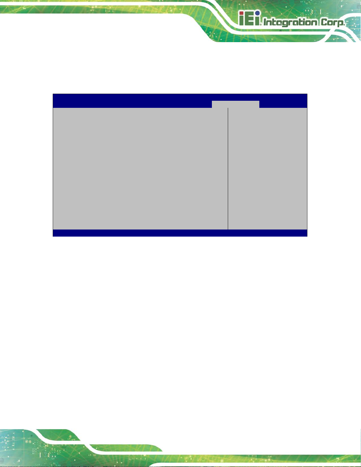
AFL3-12C-ULT3 Panel PC
Page 77
Aptio Setup Utility – Copyright (C) 2018 American Megatrends, Inc.
Main
Advanced
Chipset
Security
Boot
Save & Exit
ESC Exit
Version 2.17.1255. Copyright (C) 2018 American Megatrends, Inc.
4.7 Save & Exit
Use the Save & Exit menu (BIOS Menu 26) to load default BIOS values, optimal failsafe
values and to save configuration changes.
Save Changes and Reset
Discard Changes and Reset
Restore Defaults
Save as User Defaults
Restore User Defaults
BIOS Menu 26: Save & Exit
Save Changes and Reset
Use the Save Changes and Reset option to save the changes made to the BIOS options
Reset the system after
saving the changes.
---------------------
: Select Screen
↑ ↓: Select Item
Enter Select
F1 General Help
F2 Previous Values
F3 Optimized
Defaults
F4 Save
and to exit the BIOS configuration setup program.
Discard Changes and Reset
Use the Discard Changes and Reset option to exit the system without saving the
changes made to the BIOS configuration setup program.
Restore Defaults
Use the Restore Defaults option to load the optimal default values for each of the
parameters on the Setup menus. F3 key can be used for this operation.

AFL3-12C-ULT3 Panel PC
Page 78
Save as User Defaults
Use the Save as User Defaults option to save the c hanges done so far as user defaults.
Restore User Defaults
Use the Restore User Defaults option to restore t he user default s to all t he setup option s.

AFL3-12C-ULT3 Panel PC
Page 79
Chapter
5
5 System Maintenance

AFL3-12C-ULT3 Panel PC
Page 80
Failure to take ESD precautions during the maintenance of the
may result in permanent damage to the
5.1 System Maintenance Introduction
If the components of the AFL3-12C-ULT3 fail they must be replaced. Please contact the
system reseller or vendor to purchase the replacement parts. Back cover removal
instructions for the AFL3-12C-ULT3 are described below.
5.2 Anti-static Precautions
WARNING:
AFL3-12C-ULT3
AFL3-12C-ULT3 and severe injury to the user.
Electrostatic discharge (ESD) can cause serious damage to electronic components,
including the AFL3-12C-ULT3. Dry climates are especially susceptible to ESD. It is
therefore critical that whenever the AFL3-12C-ULT3 is accessed internally, or any other
electrical component is handled, the following anti-static precautions are strictly adhered
to.
Wear an anti-static wristband: - Wearing a simple anti-static wristband can
help to prevent ESD from damaging the board.
Self-grounding: - Before handling the board touch any grounded conducting
material. During the time the board is handled, f requently touch any
conducting materials that are connected to the ground.
Use an anti-static pad: - When configuring the AFL3-12C-ULT3, place it on
an anti-static pad. This reduces the possibility of ESD damaging the
AFL3-12C-ULT3.
Only handle the edges of the PCB: - When handling the PCB, hold the PCB
by the edges.

AFL3-12C-ULT3 Panel PC
Page 81
5.3 Turn off the Power
WARNING:
Failing to turn off the system before opening it can cause permanent
damage to the system and serious or fatal injury to the user.
Before any maintenance procedures are carried out on the system, make sure the syst em
is turned off.
5.4 SO-DIMM Module Replacement
The AFL3-12C-ULT3 has one SO-DIMM module installed. To replace the SO-DIMM
module, follow the instructions below.
Step 1: Follow all anti-static procedures. See Section 5.2.
Step 2: Turn off the power. See Section 5.3.
Step 3: Remove the plastic back cover and the internal aluminum cover. See
Section 3.4 above.
Step 4: Locate the SO-DIMM module (Figure 5-1).

AFL3-12C-ULT3 Panel PC
Page 82
Figure 5-1: SO-DIMM module Location
Step 5: Remove the DDR4 memory module by pulling both the spring retainer clips
outward from the socket.
Step 6: Grasp the DDR4 memory module by the edges and car efully pull it out of the
socket.
Step 7: Install the new DDR4 memory module by pushing i t into the socket at a 20º
angle (Figure 5-2).
Step 8: Gently push the memory module downwards and the arms clip into place
(Figure 5-2).
Figure 5-2: SO-DIMM Installation

AFL3-12C-ULT3 Panel PC
Page 83
Step 9: Reinstall the internal aluminum cover and the plastic back cover using the
previously removed retention screws. Step 0:
WARNING:
Failing to reinstall the cover may result in permanent damage to the
system. Please make sure all coverings are p roperly installed.

AFL3-12C-ULT3 Panel PC
Page 84
Chapter
6
6 Interface Connectors
 Loading...