

Page 1
AFL3-08A-BT Panel PC
MODEL:
AFL3-08A-BT
Flat Bezel Panel PC with Intel® Celeron® J1900 Quad-Core CPU,
Touchscreen, Dual USB 3.0, Dual GbE LAN, RS-232,
HD Audio, Wi-Fi 802.11a/b/g/n/ac and RoHS
User Manual
User Manual
Rev. 1.01 - November 25, 2016
Page I
Page 2
AFL3-08A-BT Panel PC
Revision
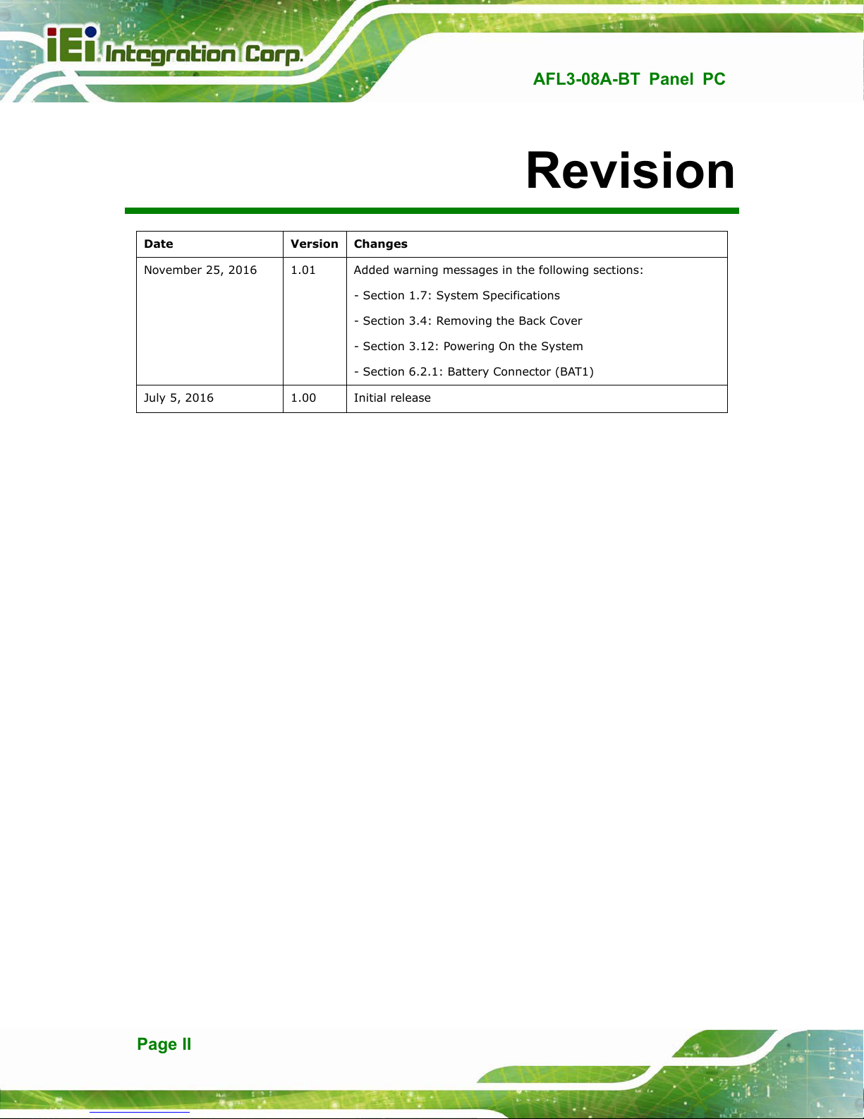
Date Version Changes
November 25, 2016 1.01 Added warning messages in the following sections:
- Section 1.7: System Specifications
tion 3.4: Removing the Back Cover
- Sec
tion 3.12: Powering On the System
- Sec
tion 6.2.1: Battery Connector (BAT1)
- Sec
July 5, 2016 1.00 Initial release
Page II
Page 3
AFL3-08A-BT Panel PC
Safety Instructions
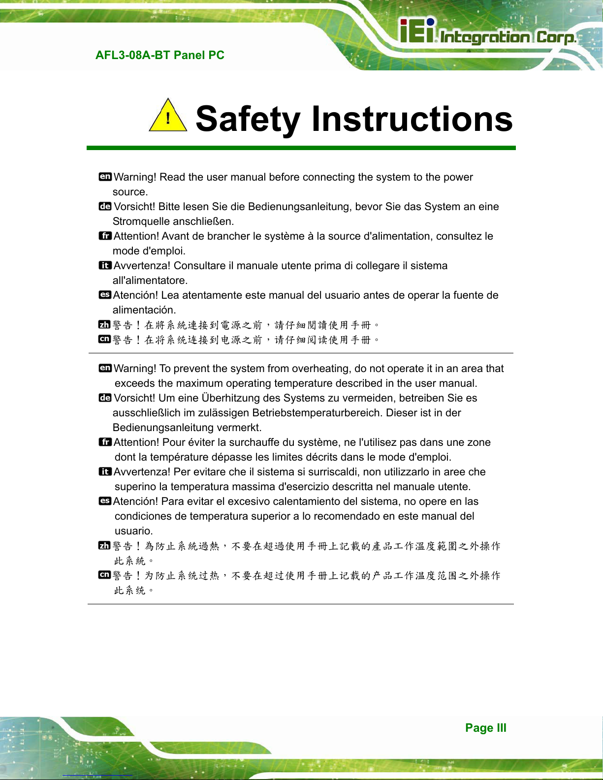
Warning! Read the user manual before connecting the system to the power
source.
Vorsicht! Bitte lesen Sie die Bedienungsanleitung, bevor Sie das System an eine
Stromquelle anschließen.
Attention! Avant de brancher le système à la source d'alimentation, consultez le
mode d'emploi.
Avvertenza! Consultare il manuale utente prima di collegare il sistema
all'alimentatore.
Atención! Lea atentamente este manual del usuario antes de operar la fuente de
alimentación.
警告!在將系統連接到電源之前,請仔細閱讀使用手冊
警告!在将系统连接到电源之前,请仔细阅读使用手册
Warning! To prevent the system from overheating, do not operate it in an area that
exceeds the maximum operating temperature described in the user manual.
Vorsicht! Um eine Überhitzung des Systems zu vermeiden, betreiben Sie es
ausschließlich im zulässigen Betriebstemperaturbereich. Dieser ist in der
Bedienungsanleitung vermerkt.
Attention! Pour éviter la surchauffe du système, ne l'utilisez pas dans une zone
dont la température dépasse les limites décrits dans le mode d'emploi.
Avvertenza! Per evitare che il sistema si surriscaldi, non utilizzarlo in aree che
superino la temperatura massima d'esercizio descritta nel manuale utente.
Atención! Para evitar el excesivo calentamiento del sistema, no opere en las
condiciones de temperatura superior a lo recomendado en este manual del
usuario.
警告!為防止系統過熱,不要在超過使用手冊上記載的產品工作溫度範圍之外操作
此系統
警告!为防止系统过热,不要在超过使用手册上记载的产品工作温度范围之外操作
此系统
Page III
Page 4
AFL3-08A-BT Panel PC
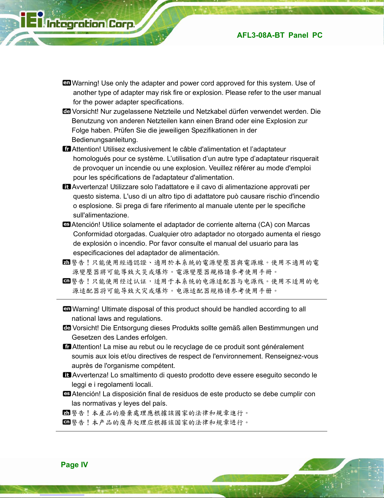
Warning! Use only the adapter and power cord approved for this system. Use of
another type of adapter may risk fire or explosion. Please refer to the user manual
for the power adapter specifications.
Vorsicht! Nur zugelassene Netzteile und Netzkabel dürfen verwendet werden. Die
Benutzung von anderen Netzteilen kann einen Brand oder eine Explosion zur
Folge haben. Prüfen Sie die jeweiligen Spezifikationen in der
Bedienungsanleitung.
Attention! Utilisez exclusivement le câble d'alimentation et l’adaptateur
homologués pour ce système. L’utilisation d’un autre type d’adaptateur risquerait
de provoquer un incendie ou une explosion. Veuillez référer au mode d'emploi
pour les spécifications de l'adaptateur d'alimentation.
Avvertenza! Utilizzare solo l'adattatore e il cavo di alimentazione approvati per
questo sistema. L'uso di un altro tipo di adattatore può causare rischio d'incendio
o esplosione. Si prega di fare riferimento al manuale utente per le specifiche
sull'alimentazione.
Atención! Utilice solamente el adaptador de corriente alterna (CA) con Marcas
Conformidad otorgadas. Cualquier otro adaptador no otorgado aumenta el riesgo
de explosión o incendio. Por favor consulte el manual del usuario para las
especificaciones del adaptador de alimentación.
警告!只能使用經過認證適用於本系統的電源變壓器與電源線使用不適用的電
源變壓器將可能導致火災或爆炸電源變壓器規格請參考使用手冊
警告!只能使用经过认证,适用于本系统的电源适配器与电源线使用不适用的电
源适配器将可能导致火灾或爆炸电源适配器规格请参考使用手册
Warning! Ultimate disposal of this product should be handled according to all
national laws and regulations.
Vorsicht! Die Entsorgung dieses Produkts sollte gemäß allen Bestimmungen und
Gesetzen des Landes erfolgen.
Attention! La mise au rebut ou le recyclage de ce produit sont généralement
soumis aux lois et/ou directives de respect de l'environnement. Renseignez-vous
auprès de l'organisme compétent.
Avvertenza! Lo smaltimento di questo prodotto deve essere eseguito secondo le
leggi e i regolamenti locali.
Atención! La disposición final de residuos de este producto se debe cumplir con
las normativas y leyes del país.
警告!本產品的廢棄處理應根據該國家的法律和規章進行
警告!本产品的废弃处理应根据该国家的法律和规章进行
Page IV
Page 5
AFL3-08A-BT Panel PC
COPYRIGHT NOTICE
The information in this document is subject to change without prior notice in order to
improve reliability, design and function and does not represent a commitment on the part
of the manufacturer.
In no event will the manufacturer be liable for direct, indirect, special, incidental, or
consequential damages arising out of the use or inability to use the product or
documentation, even if advised of the possibility of such damages.
This document contains proprietary information protected by copyright. All rights are
Copyright
reserved. No part of this manual may be reproduced by any mechanical, electronic, or
other means in any form without prior written permission of the manufacturer.
TRADEMARKS
All registered trademarks and product names mentioned herein are used for identification
purposes only and may be trademarks and/or registered trademarks of their respective
owners.
Page V
Page 6
AFL3-08A-BT Panel PC
Manual Conventions
WARNING
Warnings appear where overlooked details may cause damage to the
equipment or result in personal injury. Warnings should be taken
seriously.
CAUTION
Cautionary messages should be heeded to help reduce the chance of
losing data or damaging the product.
NOTE
These messages inform the reader of essential but non-critical
information. These messages should be read carefully as any directions
or instructions contained therein can help avoid making mistakes.
HOT SURFACE
This symbol indicates a hot surface that should not be touched without
taking care.
Page VI
Page 7
AFL3-08A-BT Panel PC
3.11 Mounting the System
The methods of mounting the AFL3-08A-BT are listed below.
Wall mounting
Panel mounting
Rack mounting
Arm mounting
Stand mounting
V-Stand mounting
The mounting methods are described below.
3.11.1 Wall Mounting
To mount the flat bezel panel PC onto the wall, please follow the steps below.
Step 1: Select the location on the wall for the wall-mounting bracket.
Step 2: Carefully mark the locations of the four screw holes in the bracket on the wall.
Step 3: Drill four pilot holes at the marked locations on the wall for the bracket retention
screws.
Step 4: Align the wall-mounting bracket screw holes with the pilot holes.
Step 5: Secure the mounting-bracket to the wall by inserting the retention screws into
the four pilot holes and tightening them (Figure 3-11).
Page 27
Page 8

AFL3-08A-BT Panel PC
Figure 3-11: Wall-mounting Bracket
Step 6: Insert the four monitor mounting screws provided in the wall mount kit into the
four screw holes on the real panel of the flat bezel panel PC and tighten until the
screw shank is secured against the rear panel (Figure 3-12).
WARNING:
Please use the M4 screws provided in the wall mount kit for the rear panel.
If the screw is missing, the thread depth of the replacement screw should
be not more than 4 mm.
Page 28
Page 9
AFL3-08A-BT Panel PC
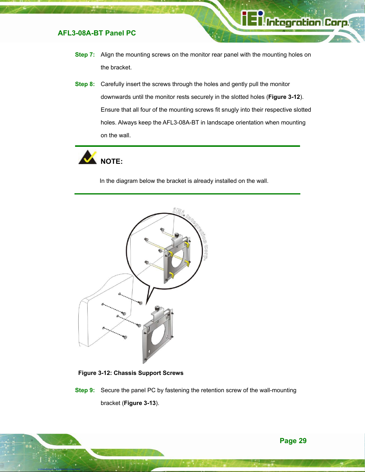
Step 7: Align the mounting screws on the monitor rear panel with the mounting holes on
the bracket.
Step 8: Carefully insert the screws through the holes and gently pull the monitor
downwards until the monitor rests securely in the slotted holes (Figure 3-12).
re that all four of the mounting screws fit snugly into their respective slotted
Ensu
holes. Always keep the AFL3-08A-BT in landscape orientation when mounting
on the wall.
NOTE:
In the diagram below the bracket is already installed on the wall.
Figure 3-12: Chassis Support Screws
Step 9: Secure the panel PC by fastening the retention screw of the wall-mounting
bracket (Figure 3-13).
Page 29
Page 10

AFL3-08A-BT Panel PC
Figure 3-13: Secure the Panel PC
3.11.2 Panel Mounting
To mount the AFL3-08A-BT flat bezel panel PC into a panel, please follow the steps
below.
Step 1: Select the position on the panel to mount the panel PC.
Step 2: Cut out a section corresponding to the size shown below. The size must be
smaller then the outer edge.
Page 30
Figure 3-14: Cutout Dimensions
Page 11
AFL3-08A-BT Panel PC
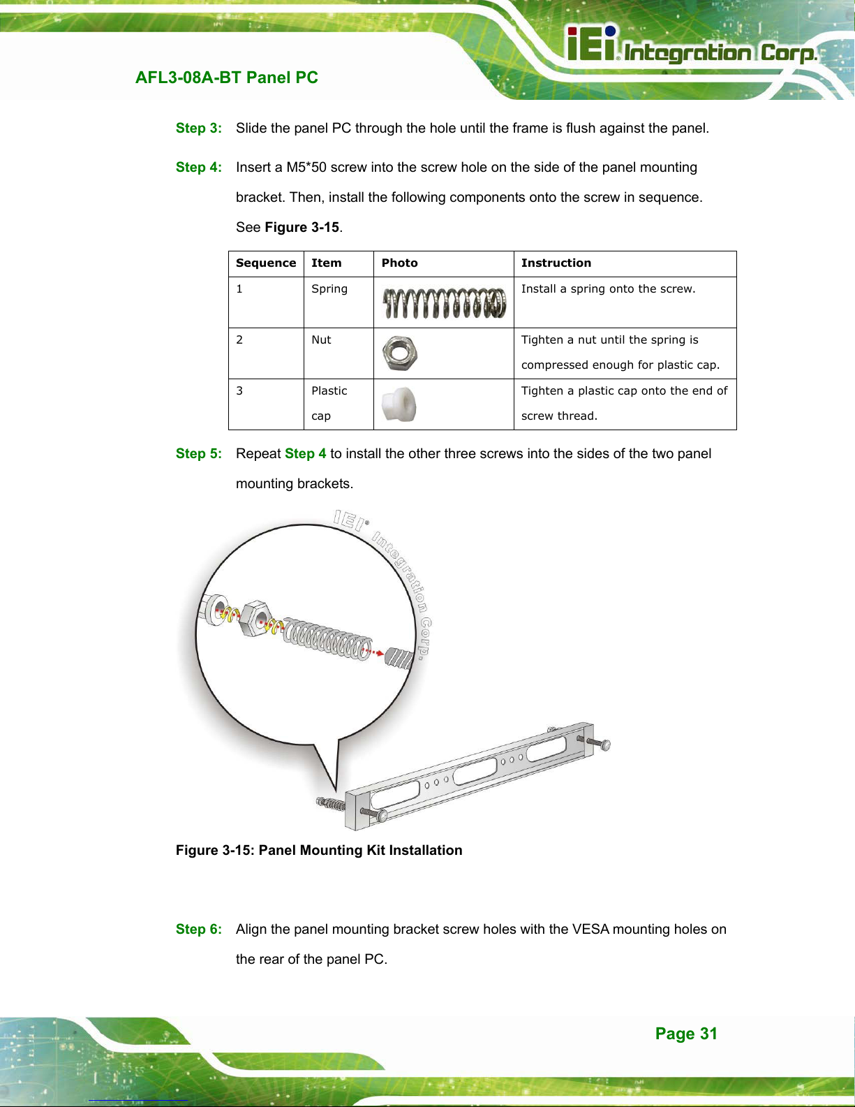
Step 3: Slide the panel PC through the hole until the frame is flush against the panel.
Step 4: Insert a M5*50 screw into the screw hole on the side of the panel mounting
bracket. Then, install the following components onto the screw in sequence.
See Figure 3-15.
Sequence Item Photo Instruction
1 Spring
2 Nut
3 Plastic
cap
Install a spring onto the screw.
Tighten a nut until the spring is
compressed enough for plastic cap.
Tighten a plastic cap onto the end of
screw thread.
Step 5: Repeat Step 4 to install the other three screws into the sides of the two panel
mounting brackets.
Figure 3-15: Panel Mounting Kit Installation
Step 6: Align the panel mounting bracket screw holes with the VESA mounting holes on
the rear of the panel PC.
Page 31
Page 12

Step 7: Secure the two panel mounting brackets to the rear of the panel PC by inserting
the four retention screws into the VESA mounting holes and tightening them
AFL3-08A-BT Panel PC
(Figure 3-16).
Step 0:
NOTE:
The panel mounting kit described in this section is an optional item. To
purchase it, please contact an IEI sales representative.
Figure 3-16: Securing Panel Mounting Brackets
3.11.3 Cabinet and Rack Installation
The AFL3-08A-BT flat bezel panel PC can be installed into a cabinet or rack. The
installation procedures are similar to the panel mounting installation. To do this, please
follow the steps below:
Page 32
Page 13

AFL3-08A-BT Panel PC
NOTE:
When purchasing the cabinet/rack installation bracket, make sure it is
compatible with both the AFL3-08A-BT flat bezel panel PC and the
rack/cabinet into which the AFL3-08A-BT is installed.
Step 1: Slide the rear chassis of the AFL3-08A-BT panel PC through the rack/cabinet
bracket until the frame is flush against the front of the bracket (Figure 3-17).
Figure 3-17: Rack/Cabinet Bracket Installation
Step 2: Insert a M5*50 screw into the screw hole on the side of the rack mounting
bracket. Then, install the following components onto the screw in sequence.
See Figure 3-15.
Sequence Item Photo Instruction
1 Spring
2 Nut
3 Plastic
cap
Install a spring onto the screw.
Tighten a nut until the spring is
compressed enough for plastic cap.
Tighten a plastic cap onto the end of
screw thread.
Page 33
Page 14

Step 3: Repeat Step 4 to install the other three screws into the sides of the two rack
mounting brackets.
AFL3-08A-BT Panel PC
Figure 3-18: Rack Mounting Kit Installation
Step 4: Align the rack mounting bracket screw holes with the VESA mounting holes on
the rear of the panel PC.
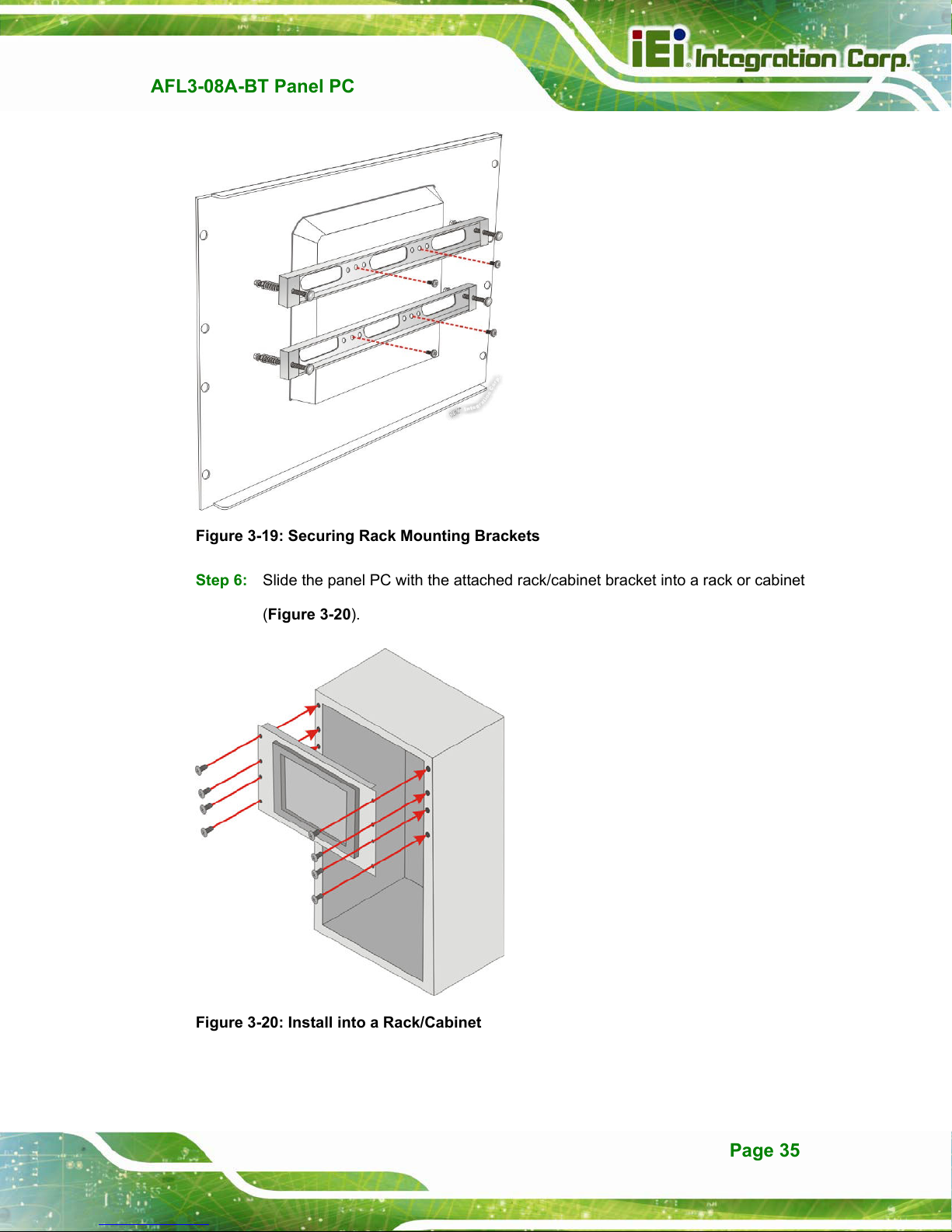
Step 5: Secure the two rack mounting brackets to the rear of the panel PC by inserting
the four retention screws into the VESA mounting holes and tightening them
(Figure 3-19).
NOTE:
The rack mounting kit described in this section is an optional item. To
purchase it, please contact an IEI sales representative.
Page 34
Page 15
AFL3-08A-BT Panel PC
Figure 3-19: Securing Rack Mounting Brackets
Step 6: Slide the panel PC with the attached rack/cabinet bracket into a rack or cabinet
(Figure 3-20).
Figure 3-20: Install into a Rack/Cabinet
Page 35
Page 16
Step 7: Once the panel PC with the attached rack/cabinet bracket has been properly
inserted into the rack or cabinet, secure the front of the rack/cabinet bracket to
AFL3-08A-BT Panel PC
the front of the rack or cabinet (Figure 3-20).
3.11.4 Arm Mounting
The AFL3-08A-BT is VESA (Video Electronics Standards Association) compliant and can
be mounted on an arm with a 75 mm interface pad. To mount the AFL3-08A-BT on an arm,
please follow the steps below.
Step 1: The arm is a separately purchased item. Please correctly mount the arm onto
the surface it uses as a base. To do this, refer to the installation documentation
that came with the mounting arm.
NOTE:
When purchasing the arm please ensure that it is VESA compliant and that
the arm has a 75 mm interface pad. If the mounting arm is not VESA
compliant it cannot be used to support the AFL3-08A-BT flat bezel panel
PC.
Step 2: Once the mounting arm has been firmly attached to the surface, lift the flat bezel
panel PC onto the interface pad of the mounting arm.
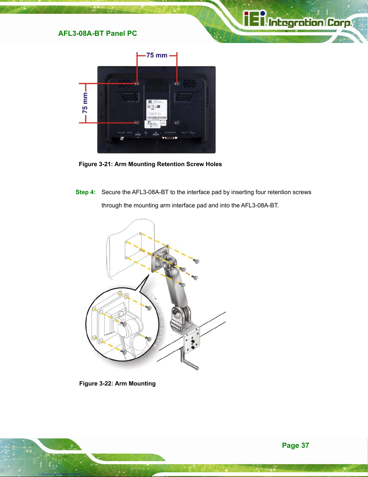
Step 3: Align the retention screw holes on the mounting arm interface with those in the
flat bezel panel PC (Figure 3-21).
Page 36
Page 17
AFL3-08A-BT Panel PC
Figure 3-21: Arm Mounting Retention Screw Holes
Step 4: Secure the AFL3-08A-BT to the interface pad by inserting four retention screws
through the mounting arm interface pad and into the AFL3-08A-BT.
Step 0:
Figure 3-22: Arm Mounting
Page 37
Page 18
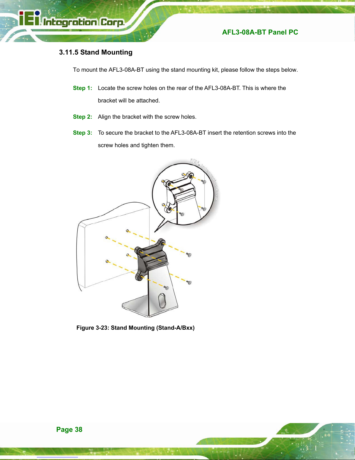
3.11.5 Stand Mounting
To mount the AFL3-08A-BT using the stand mounting kit, please follow the steps below.
Step 1: Locate the screw holes on the rear of the AFL3-08A-BT. This is where the
bracket will be attached.
Step 2: Align the bracket with the screw holes.
Step 3: To secure the bracket to the AFL3-08A-BT insert the retention screws into the
screw holes and tighten them.
AFL3-08A-BT Panel PC
Figure 3-23: Stand Mounting (Stand-A/Bxx)
Page 38
Page 19

AFL3-08A-BT Panel PC
3.11.6 V-Stand Mounting
To mount the AFL3-08A-BT using the optional V-Stand mounting kit, please follow the
steps below.
Step 1: Carefully mark the locations of the four V-Stand screw holes on the mounting
area. Drill four pilot holes at the marked locations for the V-Stand retention
screws.
Figure 3-24: Drill Pilot Holes for V-Stand
Step 2: Align the screw holes on the V-Stand with the VESA mount screw holes on the
system rear panel.
Step 3: Insert the four VESA mount screws into the four screw holes on the system rear
panel. Adjust the V-Stand to a proper position.
Step 4: Tighten until the screw shank is secured against the rear panel.
Page 39
Page 20
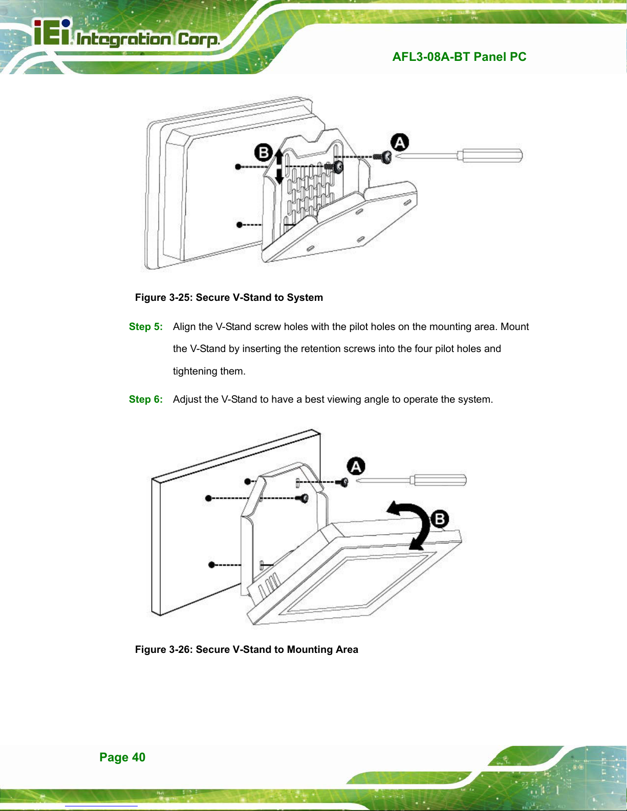
Figure 3-25: Secure V-Stand to System
Step 5: Align the V-Stand screw holes with the pilot holes on the mounting area. Mount
AFL3-08A-BT Panel PC
the V-Stand by inserting the retention screws into the four pilot holes and
tightening them.
Step 6: Adjust the V-Stand to have a best viewing angle to operate the system.Step 0:
Figure 3-26: Secure V-Stand to Mounting Area
Page 40
Page 21
AFL3-W15B-H81 Panel PC
MODEL:
AFL3-W15B-H81
Flat Bezel Panel PC with Intel® H81 Chipset, Touchscreen,
Dual GbE LAN, Wi-Fi 802.11a/b/g/n/ac, Dual USB 3.0,
2-Megapixel Camera and IP 64 Compliant Front Panel
User Manual
User Manual
Rev. 1.00 - July 1, 2015
Page i
Page 22

Date Version Changes
July 1, 2015 1.00 Initial release
AFL3-W15B-H81 Panel PC
Revision
Page ii
Page 23

AFL3-W15B-H81 Panel PC
COPYRIGHT NOTICE
The information in this document is subject to change without prior notice in order to
improve reliability, design and function and does not represent a commitment on the part
of the manufacturer.
In no event will the manufacturer be liable for direct, indirect, special, incidental, or
consequential damages arising out of the use or inability to use the product or
documentation, even if advised of the possibility of such damages.
This document contains proprietary information protected by copyright. All rights are
Copyright
reserved. No part of this manual may be reproduced by any mechanical, electronic, or
other means in any form without prior written permission of the manufacturer.
TRADEMARKS
All registered trademarks and product names mentioned herein are used for identification
purposes only and may be trademarks and/or registered trademarks of their respective
owners.
Page iii
Page 24

AFL3-W15B-H81 Panel PC
Manual Conventions
WARNING
Warnings appear where overlooked details may cause damage to the
equipment or result in personal injury. Warnings should be taken
seriously.
CAUTION
Cautionary messages should be heeded to help reduce the chance of
losing data or damaging the product.
NOTE
These messages inform the reader of essential but non-critical
information. These messages should be read carefully as any directions
or instructions contained therein can help avoid making mistakes.
HOT SURFACE
This symbol indicates a hot surface that should not be touched without
taking care.
Page iv
Page 25

AFL3-W15B-H81 Panel PC
3 Installation
Chapter
3
Page 17
Page 26

3.1 Anti-static Precautions
WARNING:
Failure to take ESD precautions during the maintenance of the
AFL3-W15B-H81 may result in permanent damage to the
AFL3-W15B-H81 and severe injury to the user.
Electrostatic discharge (ESD) can cause serious damage to electronic components,
including the AFL3-W15B-H81. Dry climates are especially susceptible to ESD. It is
therefore critical that whenever the AFL3-W15B-H81 is accessed internally, or any other
electrical component is handled, the following anti-static precautions are strictly adhered
to.
AFL3-W15B-H81 Panel PC
Wear an anti-static wristband: Wearing a simple anti-static wristband can
help to prevent ESD from damaging the board.
Self-grounding: Before handling the board touch any grounded conducting
material. During the time the board is handled, frequently touch any
conducting materials that are connected to the ground.
Use an anti-static pad: When configuring the AFL3-W15B-H81, place it on
an anti-static pad. This reduces the possibility of ESD damaging the
AFL3-W15B-H81.
Only handle the edges of the PCB: When handling the PCB, hold the PCB
by the edges.
3.2 Installation Precautions
When installing the flat bezel panel PC, please follow the precautions listed below:
Power turned off: When installing the flat bezel panel PC, make sure the
power is off. Failing to turn off the power may cause severe injury to the body
and/or damage to the system.
Certified Engineers: Only certified engineers should install and modify
onboard functionalities.
Page 18
Page 27
3.11.1 AT Power Mode
With the AT mode selected, the power is controlled by a central power unit rather than a
power switch. The AFL3-W15B-H81 panel PC turns on automatically when the power is
connected. The AT mode benefits a production line to control multiple panel PCs from a
central management center and other applications including:
ATM
Self-service kiosk
Plant environment monitoring system
Factory automation platform
Manufacturing shop flow
3.11.2 ATX Power Mode
With the ATX mode selected, the AFL3-W15B-H81 panel PC goes in a standby mode
AFL3-W15B-H81 Panel PC
when it is turned off. The panel PC can be easily turned on via network or a power switch
in standby mode. Remote power control is perfect for advertising applications since the
broadcasting time for each panel PC can be set individually and controlled remotely. Other
possible application includes
Security surveillance
Point-of-Sale (POS)
Advertising terminal
3.12 Mounting the System
The mounting methods for the AFL3-W15B-H81 are listed below.
Wall mounting
Panel mounting
Rack mounting
Arm mounting
Stand mounting
The mounting methods are described below.
Page 28
Page 28

AFL3-W15B-H81 Panel PC
3.12.1 Wall Mounting
To mount the flat bezel panel PC onto the wall, please follow the steps below.
Step 1: Select the location on the wall for the wall-mounting bracket.
Step 2: Carefully mark the locations of the four screw holes in the bracket on the wall.
Step 3: Drill four pilot holes at the marked locations on the wall for the bracket retention
screws.
Step 4: Align the wall-mounting bracket screw holes with the pilot holes.
Step 5: Secure the mounting-bracket to the wall by inserting the retention screws into
the four pilot holes and tightening them (
Figure 3-13).
Figure 3-13: Wall-mounting Bracket
Page 29
Page 29
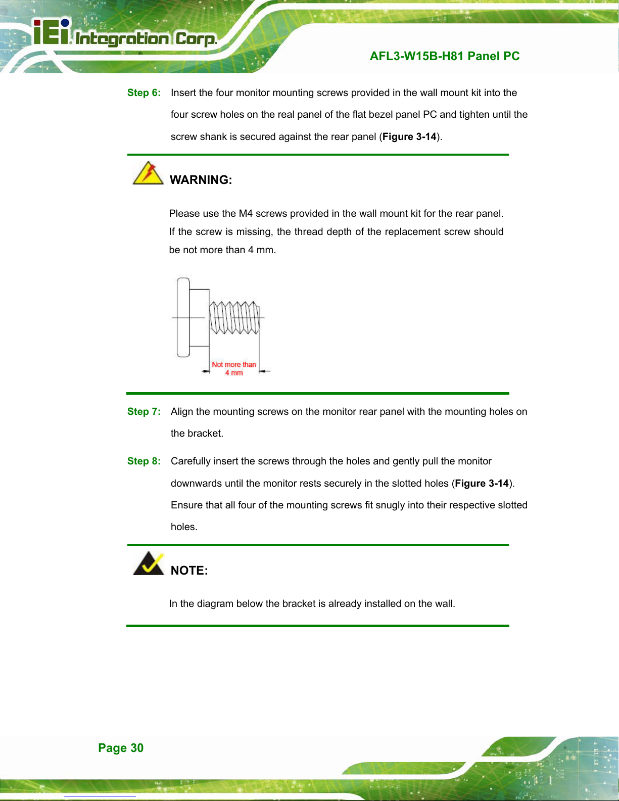
Step 6: Insert the four monitor mounting screws provided in the wall mount kit into the
four screw holes on the real panel of the flat bezel panel PC and tighten until the
AFL3-W15B-H81 Panel PC
screw shank is secured against the rear panel (
Figure 3-14).
WARNING:
Please use the M4 screws provided in the wall mount kit for the rear panel.
If the screw is missing, the thread depth of the replacement screw should
be not more than 4 mm.
Step 7: Align the mounting screws on the monitor rear panel with the mounting holes on
the bracket.
Step 8: Carefully insert the screws through the holes and gently pull the monitor
downwards until the monitor rests securely in the slotted holes (
Ensure that all four of the mounting screws fit snugly into their respective slotted
holes.
Figure 3-14).
NOTE:
In the diagram below the bracket is already installed on the wall.
Page 30
Page 30

AFL3-W15B-H81 Panel PC
Figure 3-14: Chassis Support Screws
Step 9: Secure the panel PC by fastening the retention screw of the wall-mounting
bracket (Figure 3-15).
Figure 3-15: Secure the Panel PC
Page 31
Page 31
3.12.2 Panel Mounting
To mount the AFL3-W15B-H81 flat bezel panel PC into a panel, please follow the steps
below.
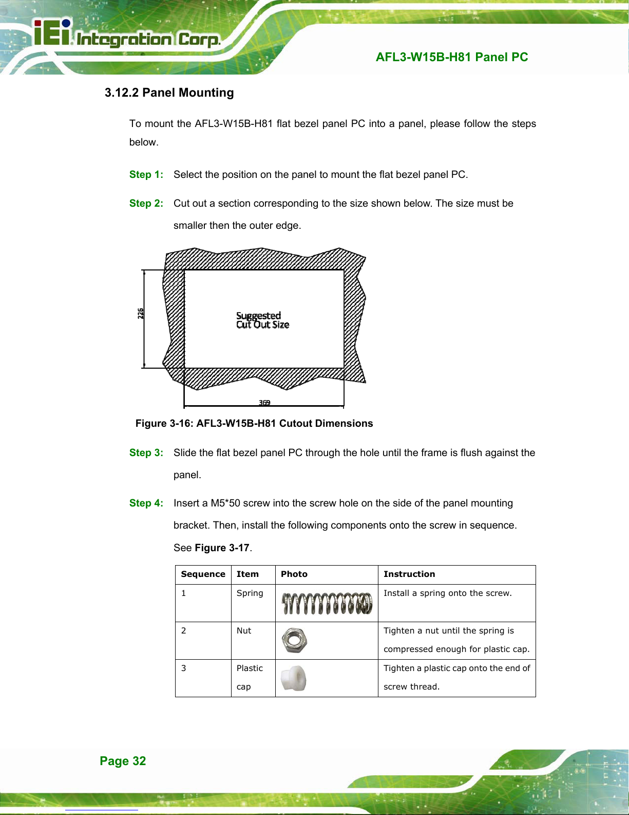
Step 1: Select the position on the panel to mount the flat bezel panel PC.
Step 2: Cut out a section corresponding to the size shown below. The size must be
smaller then the outer edge.
AFL3-W15B-H81 Panel PC
Figure 3-16: AFL3-W15B-H81 Cutout Dimensions
Step 3: Slide the flat bezel panel PC through the hole until the frame is flush against the
panel.
Step 4: Insert a M5*50 screw into the screw hole on the side of the panel mounting
bracket. Then, install the following components onto the screw in sequence.
Figure 3-17.
See
Sequence Item Photo Instruction
1 Spring
2 Nut
3 Plastic
cap
Install a spring onto the screw.
Tighten a nut until the spring is
compressed enough for plastic cap.
Tighten a plastic cap onto the end of
screw thread.
Page 32
Page 32
AFL3-W15B-H81 Panel PC
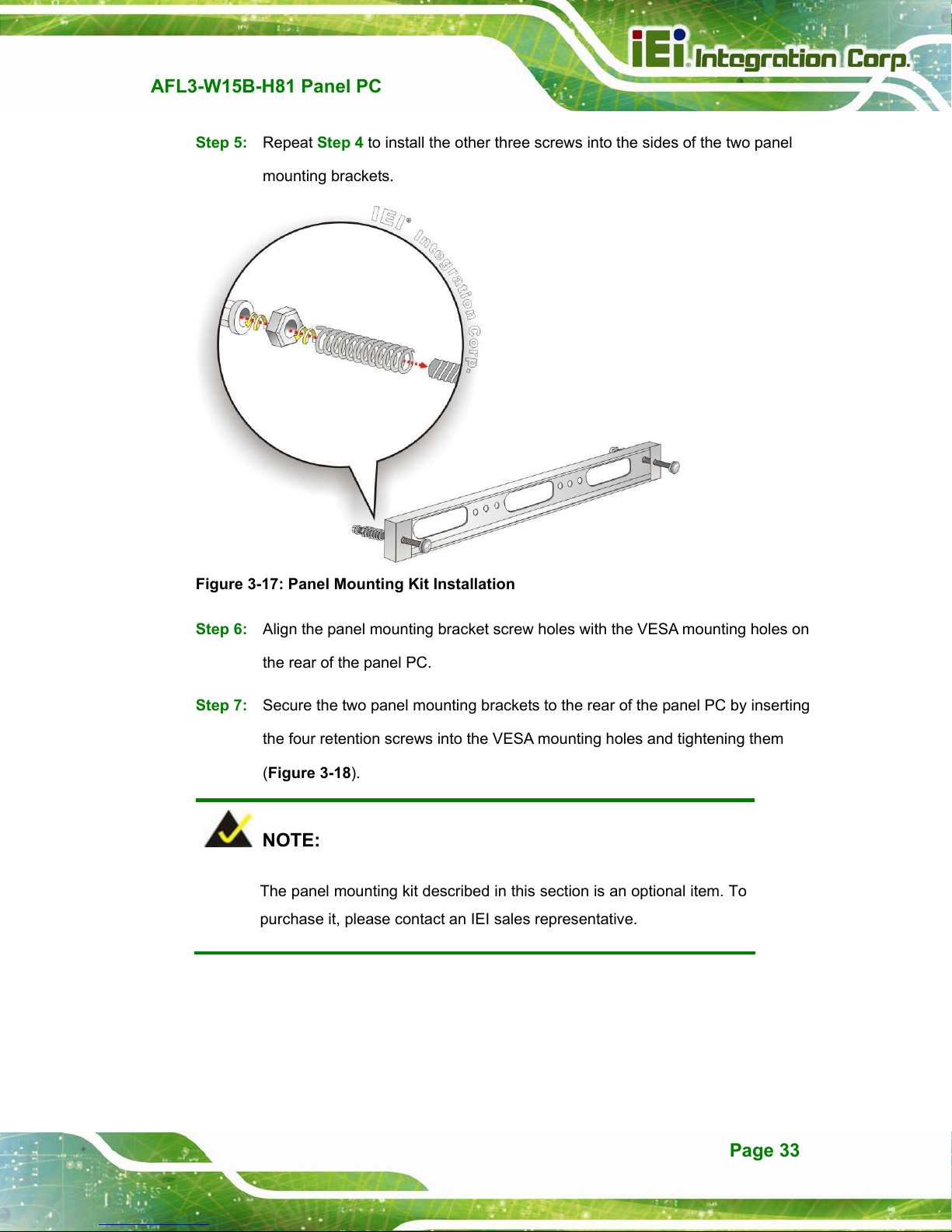
Step 5: Repeat Step 4 to install the other three screws into the sides of the two panel
mounting brackets.
Figure 3-17: Panel Mounting Kit Installation
Step 6: Align the panel mounting bracket screw holes with the VESA mounting holes on
the rear of the panel PC.
Step 7: Secure the two panel mounting brackets to the rear of the panel PC by inserting
the four retention screws into the VESA mounting holes and tightening them
Figure 3-18).
(
Step 0:
NOTE:
The panel mounting kit described in this section is an optional item. To
purchase it, please contact an IEI sales representative.
Page 33
Page 33
AFL3-W15B-H81 Panel PC
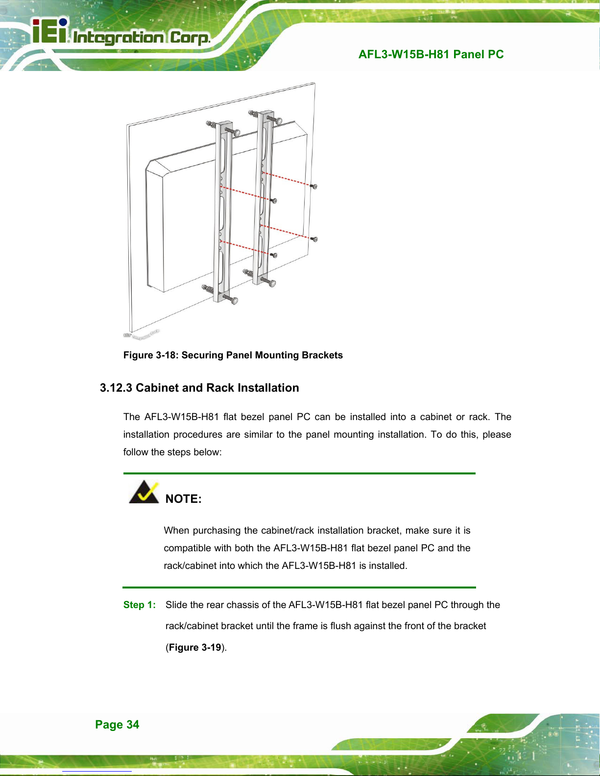
Figure 3-18: Securing Panel Mounting Brackets
3.12.3 Cabinet and Rack Installation
The AFL3-W15B-H81 flat bezel panel PC can be installed into a cabinet or rack. The
installation procedures are similar to the panel mounting installation. To do this, please
follow the steps below:
NOTE:
When purchasing the cabinet/rack installation bracket, make sure it is
compatible with both the AFL3-W15B-H81 flat bezel panel PC and the
rack/cabinet into which the AFL3-W15B-H81 is installed.
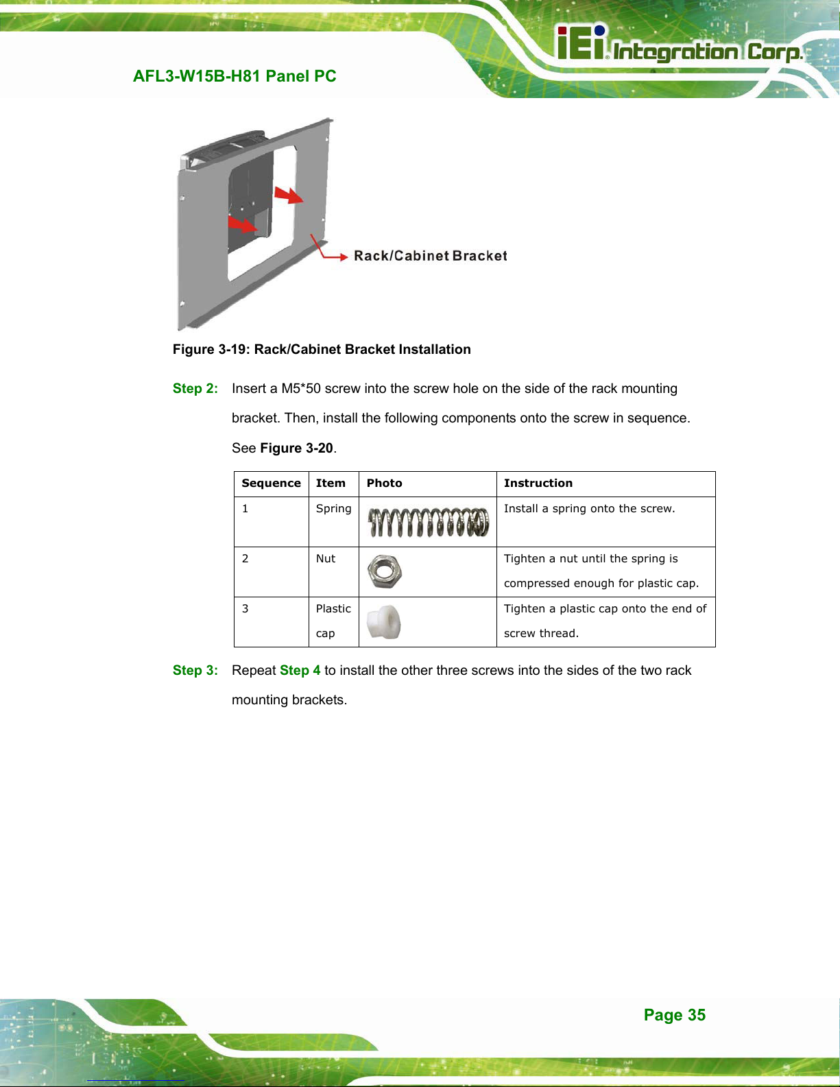
Step 1: Slide the rear chassis of the AFL3-W15B-H81 flat bezel panel PC through the
rack/cabinet bracket until the frame is flush against the front of the bracket
Figure 3-19).
(
Page 34
Page 34
AFL3-W15B-H81 Panel PC
Figure 3-19: Rack/Cabinet Bracket Installation
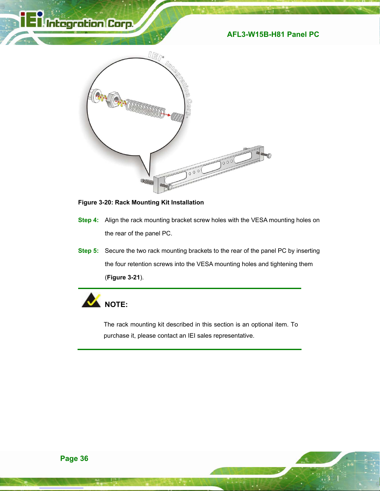
Step 2: Insert a M5*50 screw into the screw hole on the side of the rack mounting
bracket. Then, install the following components onto the screw in sequence.
Figure 3-20.
See
Sequence Item Photo Instruction
1 Spring
2 Nut
3 Plastic
cap
Install a spring onto the screw.
Tighten a nut until the spring is
compressed enough for plastic cap.
Tighten a plastic cap onto the end of
screw thread.
Step 3: Repeat Step 4 to install the other three screws into the sides of the two rack
mounting brackets.
Page 35
Page 35
AFL3-W15B-H81 Panel PC
Figure 3-20: Rack Mounting Kit Installation
Step 4: Align the rack mounting bracket screw holes with the VESA mounting holes on
the rear of the panel PC.
Step 5: Secure the two rack mounting brackets to the rear of the panel PC by inserting
the four retention screws into the VESA mounting holes and tightening them
Figure 3-21).
(
NOTE:
The rack mounting kit described in this section is an optional item. To
purchase it, please contact an IEI sales representative.
Page 36
Page 36

AFL3-W15B-H81 Panel PC
Figure 3-21: Securing Rack Mounting Brackets
Step 6: Slide the flat bezel panel PC with the attached rack/cabinet bracket into a rack or
cabinet (Figure 3-22).
Figure 3-22: Install into a Rack/Cabinet
Page 37
Page 37

Step 7: Once the flat bezel panel PC with the attached rack/cabinet bracket has been
properly inserted into the rack or cabinet, secure the front of the rack/cabinet
AFL3-W15B-H81 Panel PC
bracket to the front of the rack or cabinet (
Figure 3-22).
3.12.4 Arm Mounting
The AFL3-W15B-H81 is VESA (Video Electronics Standards Association) compliant and
can be mounted on an arm with a 75 mm or a 100 mm interface pad. To mount the
AFL3-W15B-H81 on an arm, please follow the steps below.
Step 1: The arm is a separately purchased item. Please correctly mount the arm onto
the surface it uses as a base. To do this, refer to the installation documentation
that came with the mounting arm.
NOTE:
When purchasing the arm please ensure that it is VESA compliant and that
the arm has a 75 mm a 100 mm interface pad. If the mounting arm is not
VESA compliant it cannot be used to support the AFL3-W15B-H81 flat
bezel panel PC.
Step 2: Once the mounting arm has been firmly attached to the surface, lift the flat bezel
panel PC onto the interface pad of the mounting arm.
Step 3: Align the retention screw holes on the mounting arm interface with those in the
flat bezel panel PC (
Figure 3-23).
Page 38
Page 38

AFL3-W15B-H81 Panel PC
Figure 3-23: Arm Mounting Retention Screw Holes
Step 4: Secure the AFL3-W15B-H81 to the interface pad by inserting four retention
screws through the mounting arm interface pad and into the AFL3-W15B-H81.
Step 0:
Figure 3-24: Arm Mounting
Page 39
Page 39
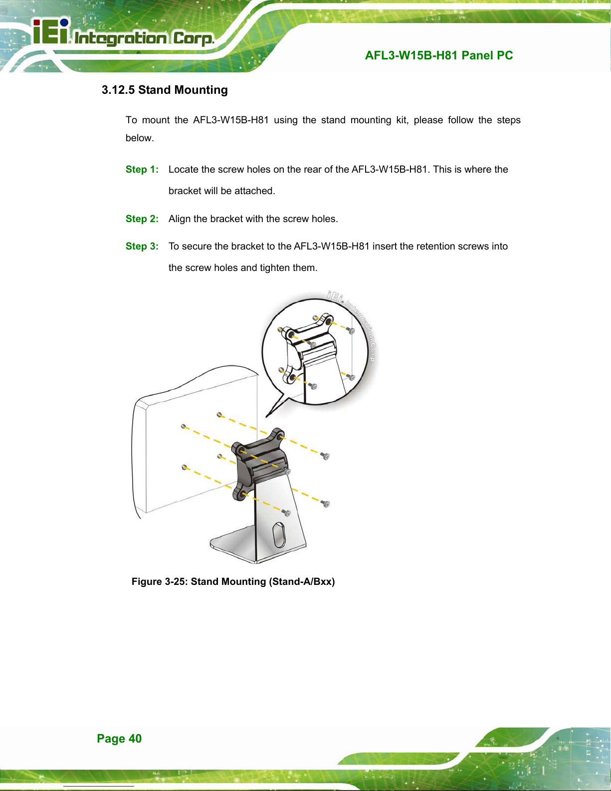
3.12.5 Stand Mounting
To mount the AFL3-W15B-H81 using the stand mounting kit, please follow the steps
below.
Step 1: Locate the screw holes on the rear of the AFL3-W15B-H81. This is where the
bracket will be attached.
Step 2: Align the bracket with the screw holes.
Step 3: To secure the bracket to the AFL3-W15B-H81 insert the retention screws into
the screw holes and tighten them.
AFL3-W15B-H81 Panel PC
Figure 3-25: Stand Mounting (Stand-A/Bxx)
Page 40
Page 40
AFL3-W10A/12A/W15A-BT Panel PC
MODEL:
AFL3-W10A/12A/W15A-BT
Flat Bezel Panel PC with Intel® Celeron® J1900 Quad-Core CPU,
Touchscreen, Dual USB 3.0, Dual GbE LAN, RS-232,
HD Audio, Wi-Fi 802.11a/b/g/n/ac and RoHS
User Manual
User Manual
Rev. 1.05 - June 27, 2016
Page I
Page 41
Date Version Changes
June 27, 2016 1.05 Added Section 3.15: OS Installation
Updated Chapter 4: BIOS Setup
March 7, 2016 1.04 Added a note in Section 1.6
Updated AFL3-W10A-BT specifications in Section 1.7
September 10, 2015 1.03 Added AFL3-W10A-BT model
July 23, 2015 1.02 Updated the following tables:
Table 6-16: USB 2.0 Connector (HUB_USB1) Pinouts
Table 6-17: USB 2.0 Connector (HUB_USB2) Pinouts
Table 6-19: USB Connector (CAM_USB2) Pinouts
AFL3-W10A/12A/W15A-BT Panel PC
Revision
Table 6-20: Webcam Connector (CAM_USB1) Pinouts
June 30, 2015 1.01 Updated the following sections:
Section 3.12.2: Panel Mounting
Section 3.12.3: Cabinet and Rack Installation
June 2, 2015 1.00 Initial release
Page II
Page 42

AFL3-W10A/12A/W15A-BT Panel PC
COPYRIGHT NOTICE
The information in this document is subject to change without prior notice in order to
improve reliability, design and function and does not represent a commitment on the part
of the manufacturer.
In no event will the manufacturer be liable for direct, indirect, special, incidental, or
consequential damages arising out of the use or inability to use the product or
documentation, even if advised of the possibility of such damages.
This document contains proprietary information protected by copyright. All rights are
Copyright
reserved. No part of this manual may be reproduced by any mechanical, electronic, or
other means in any form without prior written permission of the manufacturer.
TRADEMARKS
All registered trademarks and product names mentioned herein are used for identification
purposes only and may be trademarks and/or registered trademarks of their respective
owners.
Page III
Page 43

AFL3-W10A/12A/W15A-BT Panel PC
Manual Conventions
WARNING
Warnings appear where overlooked details may cause damage to the
equipment or result in personal injury. Warnings should be taken
seriously.
CAUTION
Cautionary messages should be heeded to help reduce the chance of
losing data or damaging the product.
NOTE
These messages inform the reader of essential but non-critical
information. These messages should be read carefully as any directions
or instructions contained therein can help avoid making mistakes.
HOT SURFACE
This symbol indicates a hot surface that should not be touched without
taking care.
Page IV
Page 44

AFL3-W10A/12A/W15A-BT Panel PC
The D-sub 9 connector pinouts of the RJ-45 to DB-9 cable are listed below.
PIN NO. DESCRIPTION PIN NO. DESCRIPTION
1 NDCD1 6 NDSR1
2 NRX1 7 NRTS1
3 NTX1 8 NCTS1
4 NDTR1 9 NRI1
5 GND
Table 3-5: DB-9 Serial Port (COM1) Pinouts
3.12 Mounting the System
The methods of mounting the AFL3-W10A/12A/W15A-BT are listed below.
Wall mounting
Panel mounting
Rack mounting
Arm mounting
Stand mounting
V-Stand mounting
The mounting methods are described below.
3.12.1 Wall Mounting
To mount the flat bezel panel PC onto the wall, please follow the steps below.
Step 1: Select the location on the wall for the wall-mounting bracket.
Step 2: Carefully mark the locations of the four screw holes in the bracket on the wall.
Step 3: Drill four pilot holes at the marked locations on the wall for the bracket retention
screws.
Step 4: Align the wall-mounting bracket screw holes with the pilot holes.
Page 33
Page 45

Step 5: Secure the mounting-bracket to the wall by inserting the retention screws into
the four pilot holes and tightening them (Figure 3-16).
AFL3-W10A/12A/W15A-BT Panel PC
Figure 3-16: Wall-mounting Bracket
Page 34
Page 46

AFL3-W10A/12A/W15A-BT Panel PC
Step 6: Insert the four monitor mounting screws provided in the wall mount kit into the
four screw holes on the real panel of the flat bezel panel PC and tighten until the
screw shank is secured against the rear panel (Figure 3-17).
WARNING:
Please use the M4 screws provided in the wall mount kit for the rear panel.
If the screw is missing, the thread depth of the replacement screw should
be not more than 4 mm.
Step 7: Align the mounting screws on the monitor rear panel with the mounting holes on
the bracket.
Step 8: Carefully insert the screws through the holes and gently pull the monitor
downwards until the monitor rests securely in the slotted holes (Figure 3-17).
re that all four of the mounting screws fit snugly into their respective slotted
Ensu
holes.
NOTE:
In the diagram below the bracket is already installed on the wall.
Page 35
Page 47

AFL3-W10A/12A/W15A-BT Panel PC
Figure 3-17: Chassis Support Screws
Step 9: Secure the panel PC by fastening the retention screw of the wall-mounting
bracket (Figure 3-18).
Figure 3-18: Secure the Panel PC
Page 36
Page 48
AFL3-W10A/12A/W15A-BT Panel PC
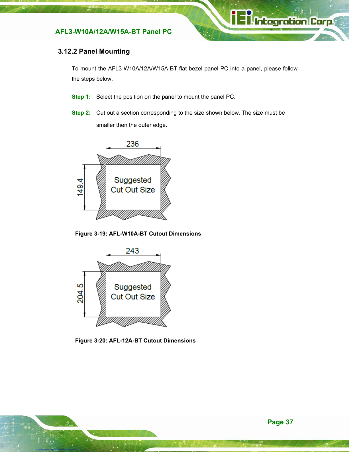
3.12.2 Panel Mounting
To mount the AFL3-W10A/12A/W15A-BT flat bezel panel PC into a panel, please follow
the steps below.
Step 1: Select the position on the panel to mount the panel PC.
Step 2: Cut out a section corresponding to the size shown below. The size must be
smaller then the outer edge.
Figure 3-19: AFL-W10A-BT Cutout Dimensions
Figure 3-20: AFL-12A-BT Cutout Dimensions
Page 37
Page 49

AFL3-W10A/12A/W15A-BT Panel PC
Figure 3-21: AFL-W15A-BT Cutout Dimensions
Step 3: Slide the panel PC through the hole until the frame is flush against the panel.
Step 4: Insert a M5*50 screw into the screw hole on the side of the panel mounting
bracket. Then, install the following components onto the screw in sequence.
See Figure 3-22.
Sequence Item Photo Instruction
1 Spring
2 Nut
3 Plastic
cap
Install a spring onto the screw.
Tighten a nut until the spring is
compressed enough for plastic cap.
Tighten a plastic cap onto the end of
screw thread.
Step 5: Repeat Step 4 to install the other three screws into the sides of the two panel
mounting brackets.
Page 38
Page 50
AFL3-W10A/12A/W15A-BT Panel PC
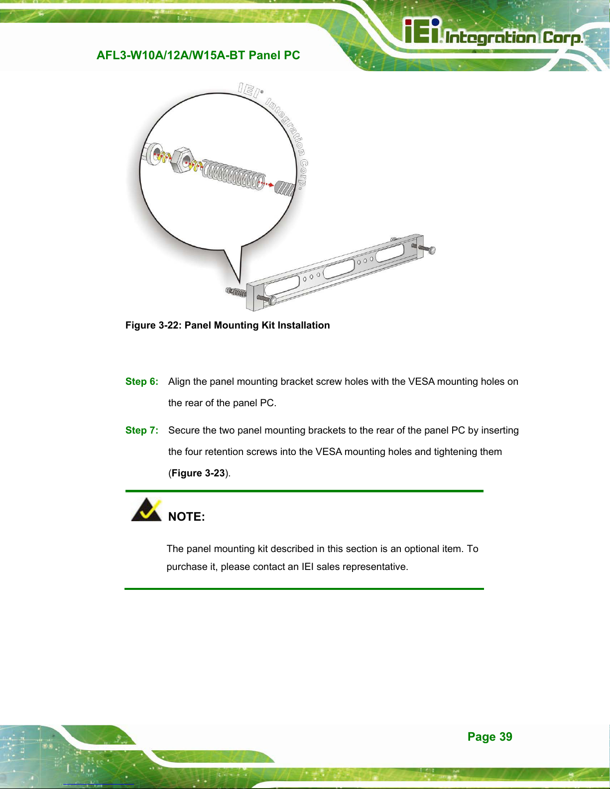
Figure 3-22: Panel Mounting Kit Installation
Step 6: Align the panel mounting bracket screw holes with the VESA mounting holes on
the rear of the panel PC.
Step 7: Secure the two panel mounting brackets to the rear of the panel PC by inserting
the four retention screws into the VESA mounting holes and tightening them
(Figure 3-23).
Step 0:
NOTE:
The panel mounting kit described in this section is an optional item. To
purchase it, please contact an IEI sales representative.
Page 39
Page 51

AFL3-W10A/12A/W15A-BT Panel PC
Figure 3-23: Securing Panel Mounting Brackets
3.12.3 Cabinet and Rack Installation
The AFL3-W10A/12A/W15A-BT flat bezel panel PC can be installed into a cabinet or rack.
The installation procedures are similar to the panel mounting installation. To do this,
please follow the steps below:
NOTE:
When purchasing the cabinet/rack installation bracket, make sure it is
compatible with both the AFL3-W10A/12A/W15A-BT flat bezel panel
PC and the rack/cabinet into which the AFL3-W10A/12A/W15A-BT is
installed.
Step 1: Slide the rear chassis of the AFL3-W10A/12A/W15A-BT panel PC through the
rack/cabinet bracket until the frame is flush against the front of the bracket
(Figure 3-24).
Page 40
Page 52
AFL3-W10A/12A/W15A-BT Panel PC
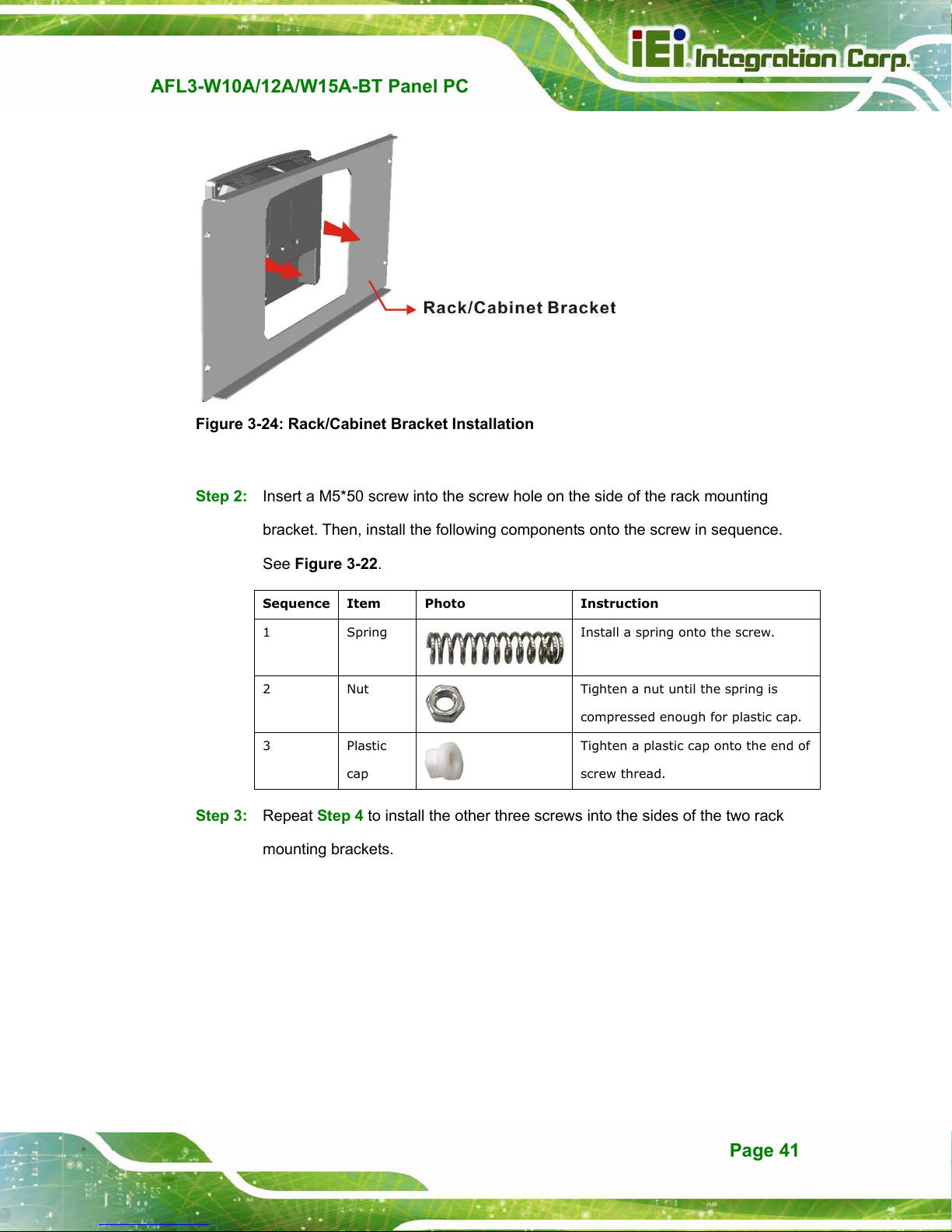
Figure 3-24: Rack/Cabinet Bracket Installation
Step 2: Insert a M5*50 screw into the screw hole on the side of the rack mounting
bracket. Then, install the following components onto the screw in sequence.
See Figure 3-22.
Sequence Item Photo Instruction
1 Spring
2 Nut
3 Plastic
cap
Install a spring onto the screw.
Tighten a nut until the spring is
compressed enough for plastic cap.
Tighten a plastic cap onto the end of
screw thread.
Step 3: Repeat Step 4 to install the other three screws into the sides of the two rack
mounting brackets.
Page 41
Page 53

AFL3-W10A/12A/W15A-BT Panel PC
Figure 3-25: Rack Mounting Kit Installation
Step 4: Align the rack mounting bracket screw holes with the VESA mounting holes on
the rear of the panel PC.
Step 5: Secure the two rack mounting brackets to the rear of the panel PC by inserting
the four retention screws into the VESA mounting holes and tightening them
(Figure 3-26).
NOTE:
The rack mounting kit described in this section is an optional item. To
purchase it, please contact an IEI sales representative.
Page 42
Page 54

AFL3-W10A/12A/W15A-BT Panel PC
Figure 3-26: Securing Rack Mounting Brackets
Step 6: Slide the panel PC with the attached rack/cabinet bracket into a rack or cabinet
(Figure 3-27).
Figure 3-27: Install into a Rack/Cabinet
Page 43
Page 55
Step 7: Once the panel PC with the attached rack/cabinet bracket has been properly
inserted into the rack or cabinet, secure the front of the rack/cabinet bracket to
AFL3-W10A/12A/W15A-BT Panel PC
the front of the rack or cabinet (Figure 3-27).
3.12.4 Arm Mounting
The AFL3-W10A/12A/W15A-BT is VESA (Video Electronics Standards Association)
compliant and can be mounted on an arm with a 75 mm or a 100 mm interface pad. To
mount the AFL3-W10A/12A/W15A-BT on an arm, please follow the steps below.
Step 1: The arm is a separately purchased item. Please correctly mount the arm onto
the surface it uses as a base. To do this, refer to the installation documentation
that came with the mounting arm.
NOTE:
When purchasing the arm please ensure that it is VESA compliant and that
the arm has a 75 mm or a 100 mm interface pad. If the mounting arm is not
VESA compliant it cannot be used to support the
AFL3-W10A/12A/W15A-BT flat bezel panel PC.
Step 2: Once the mounting arm has been firmly attached to the surface, lift the flat bezel
panel PC onto the interface pad of the mounting arm.
Step 3: Align the retention screw holes on the mounting arm interface with those in the
flat bezel panel PC (Figure 3-28 an
d Figure 3-29).
Page 44
Page 56

AFL3-W10A/12A/W15A-BT Panel PC
Figure 3-28: Arm Mounting Retention Screw Holes (10.1”)
Figure 3-29: Arm Mounting Retention Screw Holes (12.1” & 15.6”)
Step 4: Secure the AFL3-W10A/12A/W15A-BT to the interface pad by inserting four
retention screws through the mounting arm interface pad and into the
AFL3-W10A/12A/W15A-BT.
Step 0:
Page 45
Page 57

AFL3-W10A/12A/W15A-BT Panel PC
Figure 3-30: Arm Mounting
3.12.5 Stand Mounting
To mount the AFL3-W10A/12A/W15A-BT using the stand mounting kit, please follow the
steps below.
Step 1: Locate the screw holes on the rear of the AFL3-W10A/12A/W15A-BT. This is
where the bracket will be attached.
Step 2: Align the bracket with the screw holes.
Step 3: To secure the bracket to the AFL3-W10A/12A/W15A-BT insert the retention
screws into the screw holes and tighten them.
Page 46
Page 58
AFL3-W10A/12A/W15A-BT Panel PC
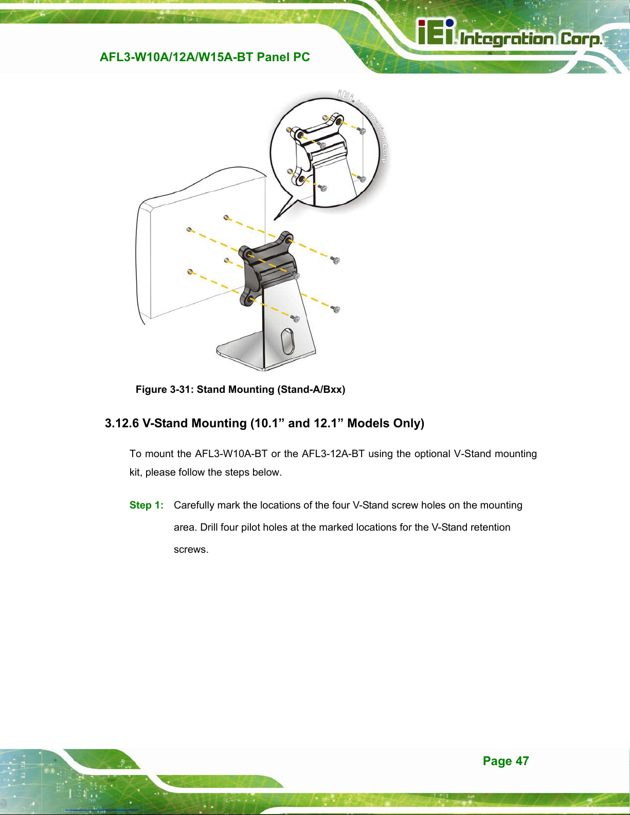
Figure 3-31: Stand Mounting (Stand-A/Bxx)
3.12.6 V-Stand Mounting (10.1” and 12.1” Models Only)
To mount the AFL3-W10A-BT or the AFL3-12A-BT using the optional V-Stand mounting
kit, please follow the steps below.
Step 1: Carefully mark the locations of the four V-Stand screw holes on the mounting
area. Drill four pilot holes at the marked locations for the V-Stand retention
screws.
Page 47
Page 59
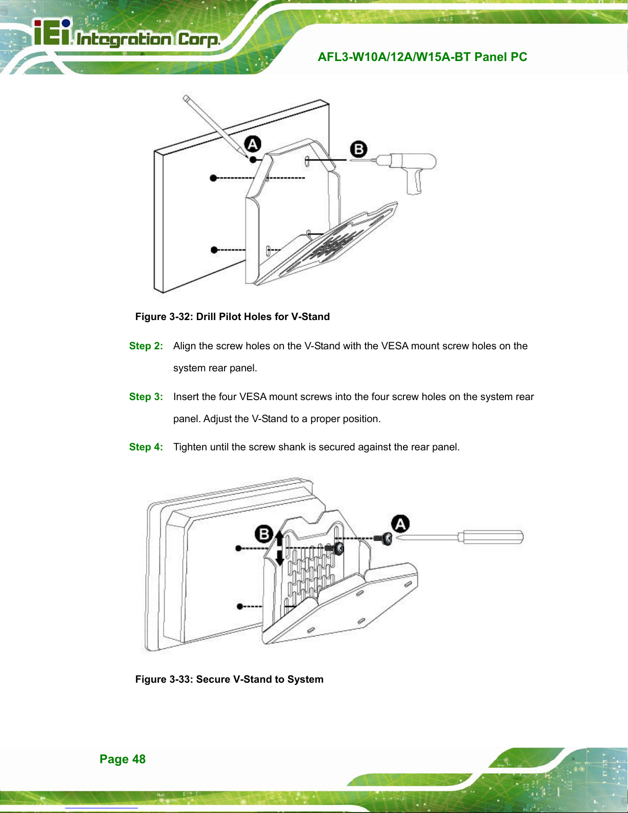
Figure 3-32: Drill Pilot Holes for V-Stand
Step 2: Align the screw holes on the V-Stand with the VESA mount screw holes on the
AFL3-W10A/12A/W15A-BT Panel PC
system rear panel.
Step 3: Insert the four VESA mount screws into the four screw holes on the system rear
panel. Adjust the V-Stand to a proper position.
Step 4: Tighten until the screw shank is secured against the rear panel.
Figure 3-33: Secure V-Stand to System
Page 48
Page 60

AFL3-W10A/12A/W15A-BT Panel PC
Step 5: Align the V-Stand screw holes with the pilot holes on the mounting area. Mount
the V-Stand by inserting the retention screws into the four pilot holes and
tightening them.
Step 6: Adjust the V-Stand to have a best viewing angle to operate the system.Step 0:
Figure 3-34: Secure V-Stand to Mounting Area
3.13 Powering On the System
To power on the system, follow the steps below:
Step 1: Connect the power cord to the power adapter. Connect the other end of the
power cord to a power source.
Step 2: Connect the power adapter to the power connector of the
AFL3-W10A/12A/W15A-BT.
Step 3: Locate the power button on the I/O panel.
Step 4: Hold down the power button until the power LED on the front panel turns on in
green.
Step 0:
Page 49
 Loading...