

Page 1

AFL2-MF-RFID-KIT Series
MODEL:
AFL2-MF-RFID-KIT
Mifare RFID reader, 13.56M Hz, w/o LED indicator,
IEI Assembly Only, R1 1
User Manual
Rev. 1.01 – August 19, 2015
Page i
Page 2

Date Version Changes
August 19, 2015 1.01 Updated supported OS (Table 1-2)
April 25, 2014 1.00 Initial release
AFL2-MF-RFID-KIT Series
Revision
Page ii
Page 3

AFL2-MF-RFID-KIT Series
COPYRIGHT NOTICE
The information in this document is subject to change without prior notice in order to
improve reliability, design and function and does not represent a commitment on the part
of the manufacturer.
In no event will the manufacturer be liable for direct, indirect, special, incidental, or
consequential damages arising out of the use or inability to use the product or
documentation, even if advised of the possibility of such damages.
This document contains proprietary information protected by copyright. All rights are
Copyright
reserved. No part of this manual may be reproduced by any mechanical, electronic, or
other means in any form without prior written permission of the manufacturer.
TRADEMARKS
All registered trademarks and product names mentioned herein are used for identification
purposes only and may be trademarks and/or registered trademarks of their respective
owners.
Page iii
Page 4

AFL2-MF-RFID-KIT Series
Table of Contents
1 INTRODUCTION.......................................................................................................... 1
1.1 AFL2-MF-RFID-KIT SERIES RFID READER OVERVIEW.......................................... 2
1.2 MODEL VARIATIONS ................................................................................................... 2
1.2.1 AFL2-MF-RFID-KIT Series Features................................................................ 2
1.3 TECHNICAL SPECIFICATIONS ...................................................................................... 3
1.4 DIMENSIONS............................................................................................................... 4
2 CONNECTORS ............................................................................................................. 5
2.1 AFL2-MF-RFID-KIT SERIES RFID READER MODULE ............................................. 6
2.1.1 AFL2-MF-RFID-KIT Series Layout................................................................... 6
2.1.2 Peripheral Interface Connectors ....................................................................... 6
2.2 INTERNAL PERIPHERAL CONNECTORS ........................................................................ 6
2.2.1 Antenna Connector ............................................................................................ 7
2.2.2 RS-232 and USB Connector (RFID1)................................................................ 7
2.2.3 CPU JTAG Port (CN1) ...................................................................................... 7
2.2.4 UART Jump (J5)................................................................................................. 8
3 INSTALLATION ...........................................................................................................9
3.1 ANTI-STATIC PRECAUTIONS...................................................................................... 10
3.1.1 Unpacking........................................................................................................ 10
4 GUI PROGRAM.......................................................................................................... 12
4.1 CHAPTER OVERVIEW................................................................................................ 13
4.2 SOFTWARE INSTALLATIONS ..................................................................................... 13
4.2.1 Virtual COM Port Driver Installation............................................................. 13
4.2.2 Hardware Installation...................................................................................... 13
4.2.3 Software GUI Installation................................................................................ 14
4.3 SOFTWARE INTERFACE............................................................................................. 17
4.3.1 Program Control Window (Lower Right-Hand Corner)................................. 18
4.3.2 Protocol Tab Window....................................................................................... 18
4.3.3 Utility Tabs Window ......................................................................................... 18
Page iv
Page 5

AFL2-MF-RFID-KIT Series
4.3.4 Flags Window................................................................................................... 18
4.3.5 Command (Request) Window........................................................................... 18
4.3.6 Log Window...................................................................................................... 18
4.3.7 Tag Data Window............................................................................................. 19
4.3.8 RSSI Window.................................................................................................... 19
4.3.9 Special Functions Window............................................................................... 20
4.3.10 Other Functions............................................................................................. 21
4.4 SET PROTOCOL......................................................................................................... 21
4.5 ISO/IEC 15693 PROTOCOL...................................................................................... 22
4.5.1 Inventory.......................................................................................................... 22
4.5.2 Read Single Block............................................................................................ 24
4.5.3 Write Single Block............................................................................................ 25
4.5.4 Lock Block........................................................................................................ 27
4.5.5 Read Multiple Blocks....................................................................................... 29
4.5.6 Write Multiple Blocks....................................................................................... 30
4.5.7 Stay Quiet......................................................................................................... 32
4.5.8 Select................................................................................................................ 33
4.5.9 Reset to Ready.................................................................................................. 34
4.5.10 Write AFI (Application Family Identifier) ..................................................... 35
4.5.11 Lock AFI (Application Family Identifier) ...................................................... 37
4.5.12 Write DSFID (Data Storage Format ID)....................................................... 38
4.5.13 Lock DSFID (Data Storage Format ID)........................................................ 39
4.5.14 Get System Info.............................................................................................. 41
4.5.15 Get Multiple-Block Security Status (Get Mult_Blk Sel Status) ...................... 42
4.6 FIND TAGS................................................................................................................ 44
A MULTIPLE TAGS WRITING INSTRUCTION...................................................... 45
A.1 INVENTORY REQUEST.............................................................................................. 46
A.2 NON - ADDRESSED MODE.................................................................................. 46
A.3 ADDRESSED MODE.............................................................................................. 47
A.4 SELECTED MODE................................................................................................. 49
B TESTDII PROGRAM................................................................................................. 54
B.1 INTRODUCTION........................................................................................................ 55
B.2 HOW TO USE ............................................................................................................ 55
Page v
Page 6

TAG INFORMATION STRUCTURE .............................................................................. 56
B.3
AFL2-MF-RFID-KIT Series
B.3.1 Tag Flag .......................................................................................................... 56
B.3.2 Tag Data.......................................................................................................... 56
B.3.3 Tag Info ........................................................................................................... 57
B.3.4 RSSI ................................................................................................................. 58
B.3.5 Request Command Type.................................................................................. 58
B.4 SOFTWARE APIS...................................................................................................... 59
BOOL IRFR_FindPort ( void ) .............................................................................. 59
BOOL IRFR_FindSinglePort ( char * Port )............................................................ 59
int IRFR_logAddFile ( char * msg ) ...................................................................... 60
Int IRFR_logAddScreen ( char * msg ).................................................................. 60
void IRFR_SetFilePath ( char * path ).................................................................. 60
void IRFR_SetLogger ( CEdit *logger )................................................................ 61
void IRFR_SetLogFile ( bool result )..................................................................... 61
void IRFR_SetLogScreen ( bool result ) ................................................................ 62
int IRFR_SetProtocol ( TagFlag tf ); .....................................................................62
int IRFR_RequestExecute ( int cmdno, char *reply, TagFlag tf, TagData *td ) .... 63
void IRFR_FindRun ( char *TagIDs, char *TagNum ).......................................... 63
void IRFR_FindStop ( void ).................................................................................. 64
void IRFR_GetUIDs ( char *reply, char *TagIDs[ ], char *TagNum )................. 64
void IRFR_GetRSSI ( char *reply, RSSI RSSIs[ ] ) ............................................... 65
void IRFR_GetBlockData ( char *reply, TagData *td ) ........................................ 65
void IRFR_GetMultiBlockData ( char *reply, TagData *td ); .............................. 66
void IRFR_GetTagInfo ( char *reply, TagInfo *ti, TagFlag tf, TagData td )......... 66
void IRFR_GetMultiBlockSecurity ( char *reply, char *SecurityData )............... 67
B.5 EXAMPLE CODE....................................................................................................... 67
C ISO/IEC 15693 REFERENCE MATERIAL ............................................................68
C.1 UID FORMAT........................................................................................................... 69
C.2 TAG MEMORY ORGANIZATION................................................................................ 69
C.3 FLAG DEFINITIONS .................................................................................................. 70
C.4 APPLICATION FAMILY IDENTIFIER (AFI) DEFINITIONS............................................ 70
D HAZARDOUS MATERIALS DISCLOSURE ......................................................... 72
D.1 HAZARDOUS MATERIALS DISCLOSURE TABLE FOR IPB PRODUCTS CERTIFIED AS
Page vi
Page 7

AFL2-MF-RFID-KIT Series
OHS COMPLIANT UNDER 2002/95/EC WITHOUT MERCURY ....................................... 73
R
Page vii
Page 8

AFL2-MF-RFID-KIT Series
List of Figures
Figure 1-1: AFL2-MF-RFID-KIT Series RFID Reader....................................................................2
Figure 2-2: AFL2-MF-RFID-KIT Series Dimensions (mm)...........................................................4
Figure 2-6: Connector and Jumper Locations.............................................................................6
Figure 4-1: FTDI Driver Installation Complete ...........................................................................13
Figure 4-2: IRFR-100 Control COM Ports...................................................................................14
Figure 4-3: Properties...................................................................................................................15
Figure 4-4: Device Manager.........................................................................................................15
Figure 4-5: Device Manager - Ports ............................................................................................16
Figure 4-6: Software Interface.....................................................................................................17
Figure 4-7: Log Window...............................................................................................................19
Figure 4-8: RSSI Window.............................................................................................................20
Figure 4-9: Set Protocol...............................................................................................................22
Figure 4-10: Inventory..................................................................................................................23
Figure 4-11: Read Single Block...................................................................................................25
Figure 4-12: Write Single Block...................................................................................................26
Figure 4-13: Lock Block...............................................................................................................28
Figure 4-14: Read Multiple Blocks..............................................................................................30
Figure 4-15: Write Multiple Block................................................................................................31
Figure 4-16: Stay Quiet ................................................................................................................32
Figure 4-17: Select........................................................................................................................34
Figure 4-18: Reset to Ready........................................................................................................35
Figure 4-19: Write AFI...................................................................................................................36
Figure 4-20: Lock AFI...................................................................................................................37
Figure 4-21: Write DSFID .............................................................................................................39
Figure 4-22: Lock DSFID..............................................................................................................40
Figure 4-23: Get System Info.......................................................................................................41
Figure 4-24: Get Multiple-Block Security Status.......................................................................43
Figure 4-25: ................................................................................................................... ................ 44
Page viii
Page 9

AFL2-MF-RFID-KIT Series
List of Tables
Table 1-1: Model Variations...........................................................................................................2
Table 1-2: Technical Specifications..............................................................................................3
Table 2-1: Peripheral Interface Connectors and Indicators .......................................................6
Table 2-2: RS-232 and USB Connector Pinouts..........................................................................7
Table 2-3: CPU JTAG Port Pinouts...............................................................................................7
Table 2-4: UART Jump Pinouts.....................................................................................................8
Table 3-1: Package List Contents...............................................................................................11
Page ix
Page 10

Page 11

AFL2-MF-RFID-KIT Series
Chapter
1
1 Introduction
Page 1
Page 12
AFL2-MF-RFID-KIT Series
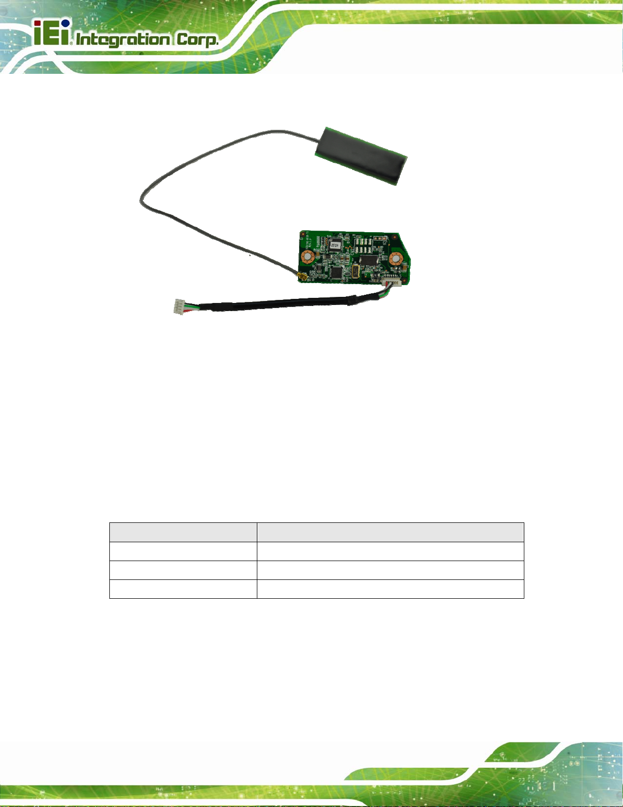
1.1 AFL2-MF-RFID-KIT Series RFID Reader Overview
Figure 1-1: AFL2-MF-RFID-KIT Series RFID Reader
The AFL2-MF-RFID-KIT Series is a RFID reader for both High Frequency (HF) and Ultra
High Frequency (UHF) RFID systems and is compliant with ISO 15693 and ISO 14443
industrial standards. The AFL2-MF-RFID-KIT Series also comes with a utility and a
software development kit (SDK) for configuring reader module and writing/ reading tags.
1.2 Model Variations
The model variations of the AFL2-MF-RFID-KIT Series are listed below.
Models Series
AFL2-MF-RFID-KIT01-R11 for AFL2-W07A/08A Series
AFL2-MF-RFID-KIT02-R11 for AFL2-W10A/10A/12A/15A/W15B/17A/W19A Series
AFL2-MF-RFID-KIT03-R11 for AFL2-W21A Series
Table 1-1: Model Variations
1.2.1 AFL2-MF-RFID-KIT Series Features
The AFL2-MF-RFID-KIT Series has the following features
13.56 MHz radio frequency industrial RFID reading module
Page 2
Page 13
AFL2-MF-RFID-KIT Series
Supports standard protocol ISO 15693 for vicinity card applications reads
multiple tags simultaneously
Tag compatibility: TI , ST , Philips , Tag-it, HF-EPC
Reader to reader anti-collision
Reads and writes tags with up to 2Kb
Single power supply and low power consumption
Various interfaces to main system
o 115.2 Kbps maximum serial communication speeds
o USB
1.3 Technical Specifications
The specifications for the Intel based embedded systems are listed below.
AFL2-MF-RFID-KIT Series
Support Protocol
RF Frequency
RF Data Rate
Baud Rate
Power Consumption
Operating Distance
Interface
Operating Temperature
Operating Humidity
Tag Compatibility
Driver Support
ISO 15693
13.56 MHz
6.62 kbps for ISO 15693
9600 Kbps ~ 115,200 Kbps
5V @ 150 mA
10 cm
RS-232 serial port or USB
0ºC ~ 60ºC
10% ~ 85% RH
RI, ST, Philips, Tag-it, HF-EPC
Windows 2000
Windows XP
Windows 7
.
Windows Server 2003
Windows Server 2008
Windows Server 2008 R2
(x86 and x64)
Table 1-2: Technical Specifications
Page 3
Page 14

1.4 Dimensions
The dimensions of the AFL2-MF-RFID-KIT Series are listed below and shown in Figure
1-2.
Figure 1-2: AFL2-MF-RFID-KIT Series Dimensions (mm)
AFL2-MF-RFID-KIT Series
Page 4
Page 15

AFL2-MF-RFID-KIT Series
Chapter
2
2 Connectors
Page 5
Page 16

AFL2-MF-RFID-KIT Series
2.1 AFL2-MF-RFID-KIT Series RFID Reader Module
The following sections describe the relevant components and ju m pers o n the RFID re ade r
module.
2.1.1 AFL2-MF-RFID-KIT Series Layout
Figure 2-1 shows the on-board peripheral connectors.
Figure 2-1: Connector and Jumper Locations
2.1.2 Peripheral Interface Connectors
Table 2-1 shows a list of the peripheral interface connectors on the AFL2-MF-RFID-KIT
Series. Detailed descriptions of these connectors can be found below.
Connector Type Label
Antenna connector IPEX type connector ANT-TYPE1
RS-232 and USB connector 6-pin header RFID1
CPU JTAG Port 8-pin CN1
UART Jump 2-pin J5
Table 2-1: Peripheral Interface Connectors and Indicators
2.2 Internal Peripheral Connectors
Page 6
This section has complete descriptions of all the internal peripheral connectors on the
AFL2-MF-RFID-KIT Series.
Page 17

AFL2-MF-RFID-KIT Series
2.2.1 Antenna Connector
CN Label: ANT-TYPE1
CN Type:
CN Location:
IPEX
See Figure 2-1
The Antenna Connector connects to the 13.56 MHz antenna module.
2.2.2 RS-232 and USB Connector (RFID1)
Pin No. Description
1 USB5V
2 D+_1
3 D-_1
4 GND
5 RFID_BUZ#
6 EN
Table 2-2: RS-232 and USB Connector Pinouts
2.2.3 CPU JTAG Port (CN1)
Pin No. Description
1 C_TCK
2 nRST
3 C_TMS
4 +3V3
5 C_TDI
6 GND
7 C_TDO
8 GND
Table 2-3: CPU JTAG Port Pinouts
Page 7
Page 18

2.2.4 UART Jump (J5)
Pin No. Description
1 TXD
2 RXD
3 GND
Table 2-4: UART Jump Pinouts
AFL2-MF-RFID-KIT Series
Page 8
Page 19

AFL2-MF-RFID-KIT Series
Chapter
3
3 Installation
Page 9
Page 20

3.1 Anti-static Precautions
WARNING:
If the following anti-static precautions are not followed, a user may be
injured and the system irreparably damaged.
Electrostatic discharge (ESD) can cause serious damage to electronic components,
including the AFL2-MF-RFID-KIT Series module. (Dry climates are especially susceptible
to ESD.) It is therefore critical that whenever the AFL2-MF-RFID-KIT Series is opened and
any electrical component handled, the following anti-static precautions are strictly adhered
to.
AFL2-MF-RFID-KIT Series
Wear an anti-static wristband: Wearing a simple an ti-static wristband can
help to prevent ESD from damaging the board.
Self-grounding: Before handling the board, touch any grounded conducting
material. During the time the board is handled, frequently touch any
conducting materials that are connected to the ground.
Use an anti-static pad: When configuring the AFL2-MF-RFID-KIT Series,
place it on an anti-static pad. This re duces the possibility of ESD damaging
the AFL2-MF-RFID-KIT Series.
3.1.1 Unpacking
After the AFL2-MF-RFID-KIT Series is received make sure the following components are
included in the package. If any of these components are missing, please contact the
AFL2-MF-RFID-KIT Series reseller or vendor where it was purchased or contact an IEI
sales representative immediately.
Quantity Item Image
Page 10
1 IRFD-100/IRFR-100
Page 21

AFL2-MF-RFID-KIT Series
1 Utility and manual CD
Table 3-1: Package List Contents
Page 11
Page 22

AFL2-MF-RFID-KIT Series
Chapter
4
4 GUI Program
Page 12
Page 23

AFL2-MF-RFID-KIT Series
4.1 Chapter Overview
This chapter describes the installation and use of the USB drivers and IRFR-100 module
control program.
4.2 Software Installations
Do not plug the module into the USB port until instructed to do so. If it is already connected
to a USB port, disconnect it now.
Software installation is a two-step process. The first step is the installation of a third-party
virtual COM port (VCP) driver, and the second part is the in stallation of the IRFR-100 GUI
program.
4.2.1 Virtual COM Port Driver Installation
To install the virtual driver, unzip the VCP_driver.rar and run the program
CDM_setup.exe. When the driver installation is complete, the following confirmation is
displayed:
Figure 4-1: FTDI Driver Installation Complete
4.2.2 Hardware Installation
At this point, attach the IRFR-100 module to an open USB port. The module can be
plugged directly into the port or attached at the end of a USB extension cable (type A, not
supplied). At this point, the power LED should be lit. Any RFID tag corresponding to a
supported protocol can be detected and is indicated by the corresponding LED.
Page 13
Page 24

4.2.3 Software GUI Installation
The software GUI is the file named IRFR-100.rar. It can be unzipped using a standard
unzip program and is a self-contained executable. Create a folder where desired on the
host PC, and unzip the executable into that folder. The program can be run from the folder,
or a shortcut can be created and placed on the desktop of the host computer. In most
cases, the program automatically detects the COM port. In case the program could not
detect the COM port, enter the COM port number (e.g., COM3) in the Select Port window
at the bottom right of the GUI as shown following, and click on the Select Port button).
Support Port: COM1 ~ COM9.
AFL2-MF-RFID-KIT Series
Page 14
Figure 4-2: IRFR-100 Control COM Ports
To determine the USB serial port that corresponds to the IRFR-100 module, right-click on
the My Computer icon on the desktop. When the drop-down menu appears, click on
Properties.
Page 25

AFL2-MF-RFID-KIT Series
Figure 4-3: Properties
On the properties window, select the Hardware tab:
Figure 4-4: Device Manager
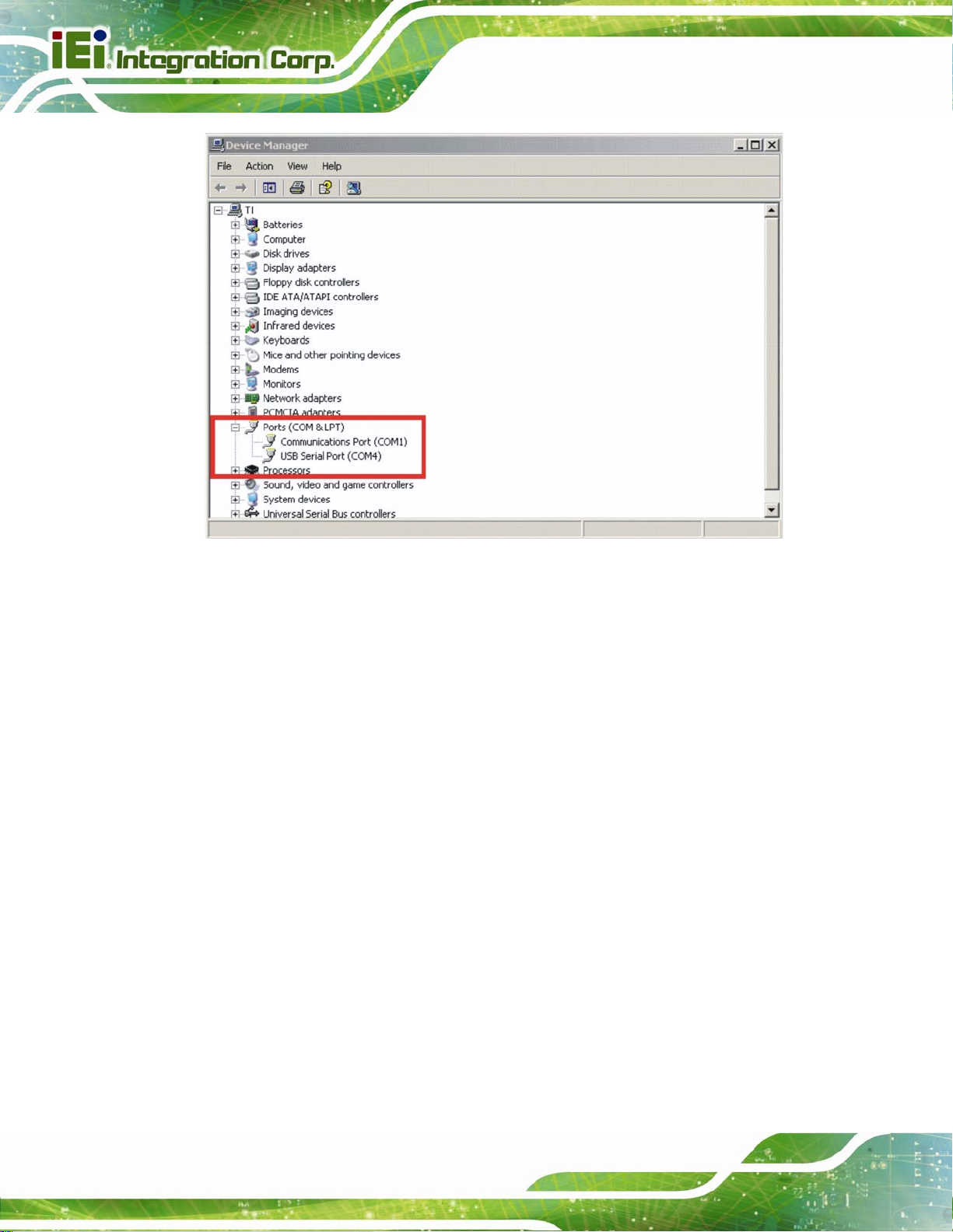
Next, click on Device Manager, then click the + sign next to Ports to expand the ports:
Page 15
Page 26
AFL2-MF-RFID-KIT Series
Figure 4-5: Device Manager - Ports
If the driver installation was successful and the module is plugged in, USB Serial Port
should appear in the list of ports, followed by a port number (in this example, COM4). The
actual port number may be different. Make note of the COM port number and ent er it in the
Select Port window of the GUI. Then select the Select Port on GUI (do not press the Enter
key). Note: If the Enter key is pressed, the program ends and the GUI closes.
Page 16
Page 27
AFL2-MF-RFID-KIT Series
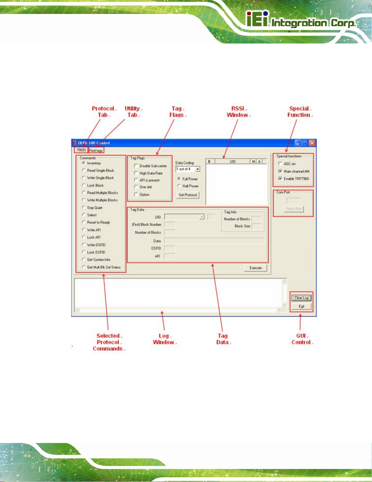
4.3 Software Interface
The GUI window is shown following. Each section of the window has a different function.
The figure shows the arrangement for the Protocol 15693 and Find Tags.
Figure 4-6: Software Interface
Page 17
Page 28

AFL2-MF-RFID-KIT Series
4.3.1 Program Control Window (Lower Right-Hand Corner)
The Select Port window allows the user to enter manually the USB serial port used by the
host computer to communicate with the IRFR-100 module.
Exit button – exits the IRFR-100 control program.
4.3.2 Protocol Tab Window
The protocol tab window selects tag protocol and program functions. Available option is:
(ISO/IEC) 15693 – vicinity cards
4.3.3 Utility Tabs Window
Find Tags – a function that reads tags of protocol 15693
4.3.4 Flags Window
This window allows the user to set flags for the 15693 protocol. Different flags may be
available for different commands. The tag window automatically updates available flags
depending on the request chosen.
4.3.5 Command (Request) Window
This window shows various request options available for protocol 15693.
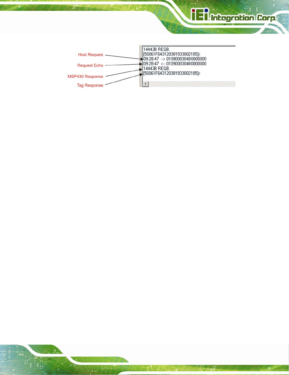
4.3.6 Log Window
The log window shows all communication frames from host computer to IRFR-100 mod ule.
The tag response is also displayed in the log window. The tag response (register content)
is always in parentheses to distinguish it from the host-to-reader data exchange. This
information is also stored in the IRFR-100.log file, located in the same file directory as
IRFR-100.exe, which can be opened by a normal text editor such as Notepad.
Page 18
Page 29
AFL2-MF-RFID-KIT Series
Figure 4-7: Log Window
4.3.7 Tag Data Window
The Tag Data window is where the user enters addresses, data, number of bits, and other
information required by certain commands. Checking certain flags in the Flag window may
activate more fields for data entry.
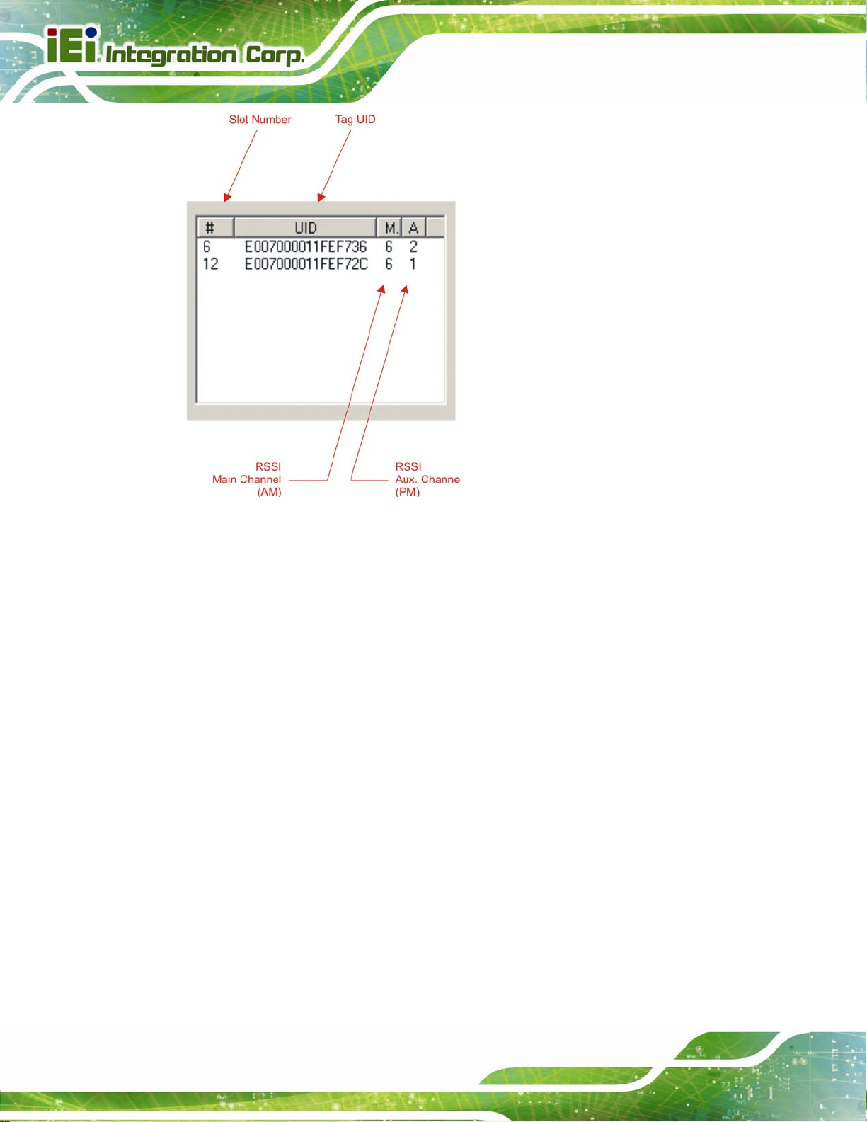
4.3.8 RSSI Window
The RSSI field displays the slot number, UID and the RSSI values of the corresponding
tag. If there was a collision and the reader performed a secon d anticollision procedure, the
slot numbers are indicated with an additional character:
A = second procedure B = third procedure and so on.
The main channel, which is AM, is used as the primary one, and PM is the auxiliary
channel. The RSSI maximum value is 7 and minimum value is 0. The corresponding RSSI
values depend on the system design (antenna + reader), and the levels can vary based on
the quality of the reception. The specifics of the corresponding input voltage levels to RSSI
levels are defined in the TRF7960 data sheet.
Page 19
Page 30
AFL2-MF-RFID-KIT Series
Figure 4-8: RSSI Window
In the preceding example, one can see that the tags in slots #6 and #12 have a
main-channel RSSI value of 6, with auxiliary-channel RSSI values of 2 and 1, respectively.
4.3.9 Special Functions Window
Special functions, such as AGC on/off, main channel AM, and enable/disable the
TRF7960.
The AGC is turned off after the power-on reset (POR) and can be enabled when desired
(especially in noisy environments). By default, the input channel is AM and can be
switched to PM if the RSSI value for the PM channel is higher than the AM.
Page 20
Page 31

AFL2-MF-RFID-KIT Series
4.3.10 Other Functions
Other functions on the main IRFR-100 control panel are:
Set protocol - which configures the program for the selected protocol once the
protocol tab has been selected
Execute button - which processes the selected command
Power control (half or full) - which can be used to simulate marginal reception
conditions. The RF output power selection enables the user to switch
between full power (200 mW) and half power (100 mW); however, the
antenna matching circuit is tuned to operate with full-power selection, and
performance is not optimal in half-power selection. This is due to the matching
on the output of the reader IC, which currently is matched for 200 mW. (The
load impedance for full power is 4 W and half power is 8 W.)
Data coding mode - which is used in conjunction with the 15693 protocol
4.4 Set Protocol
IRFR-100 control program does not automatically set the program to that protocol. The
user must manually click on the Set Protocol button:
Page 21
Page 32

“Set
Protocol”
AFL2-MF-RFID-KIT Series
Figure 4-9: Set Protocol
When the Set Protocol button is pressed, the software sets the parameters for the
corresponding protocol standard.
4.5 ISO/IEC 15693 Protocol
This section describes commands for the 15693 protocol. After a command has been
selected by clicking on the associated command button in the Commands window, the
user should set any flags as needed. If appropriate, enter data in the Tag Data window.
4.5.1 Inventory
The Inventory command is used to acquire the unique IDs (UID) of ISO 15693 tags in the
read zone. The two inventory methods supported are 16-slotted and single-slot. A
single-slot request allows all transponders in the read zone to reply to the Inventory
request. In cases where more than one tag is present, such a request would cause a data
Page 22
collision, which in turn causes a reader to send a collision error message to the GUI. A
16-slot inventory sequence decreases the likelihood of a data collision by forcing
Page 33

AFL2-MF-RFID-KIT Series
compliant transponders to respond in 1 of 16 slots, based on a portion of their UIDs. To
perform a slotted sequence, the Slot Marker/End-of-Frame request is used in conjunction
with this command. Any collision that does occur in a slotted sequence can be further
arbitrated by using the anticollision mask in an algorithm similar to that outlined in the
ISO 15693 standard.
To inventory a tag, the user should:
Step 1: Click the button for Inventory in the Commands window
Step 2: Click on any flags that must be set in the Tag Flags window
Step 3: Click on Set Protocol
Step 4: Execute the command Step 0:
Figure 4-10: Inventory
Page 23
Page 34

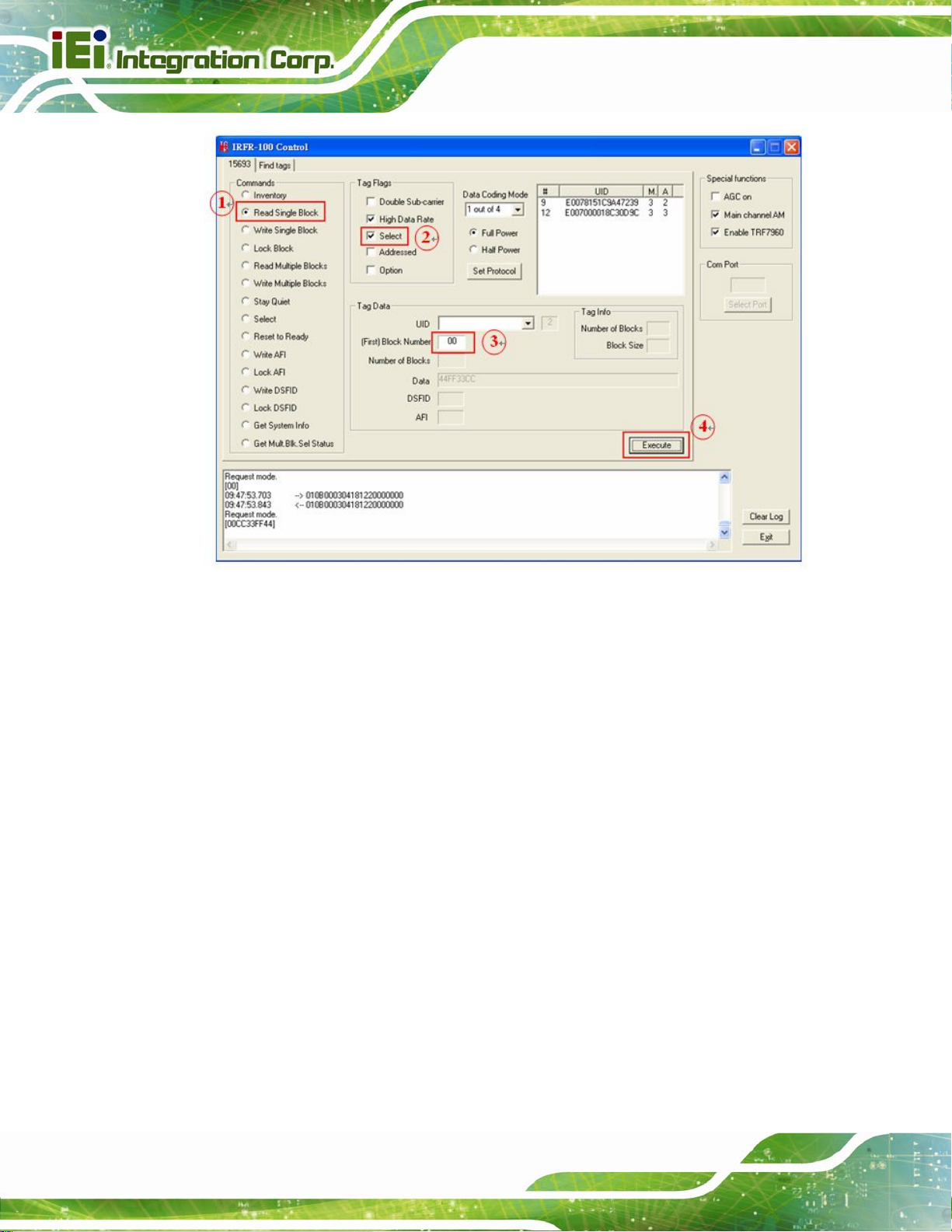
4.5.2 Read Single Block
The Read Single Block command gets the data from one memory block of the responding
tag. In addition to this data, a Block Security Status byte can be requested. This byte
shows the write-protection of the block specified [e.g., unlocked, (user/factory) locked,
etc.].
To read a single block, the user should:
Step 1: Click the button for Read Single Block in the Commands window
Step 2: Click on any flags that must be set in the Tag Flags window
Step 3: Optionally select a tag from the UID pulldown list in the Tag Data window and
set the Addressed flag (if only one tag is present, only one choice is available)
AFL2-MF-RFID-KIT Series
Step 4: Enter two hex digits corresponding to the block number in the (First) Block
Number field in the Tag Data window
Step 5: Execute the command. Step 0:
Page 24
Page 35

AFL2-MF-RFID-KIT Series
Figure 4-11: Read Single Block
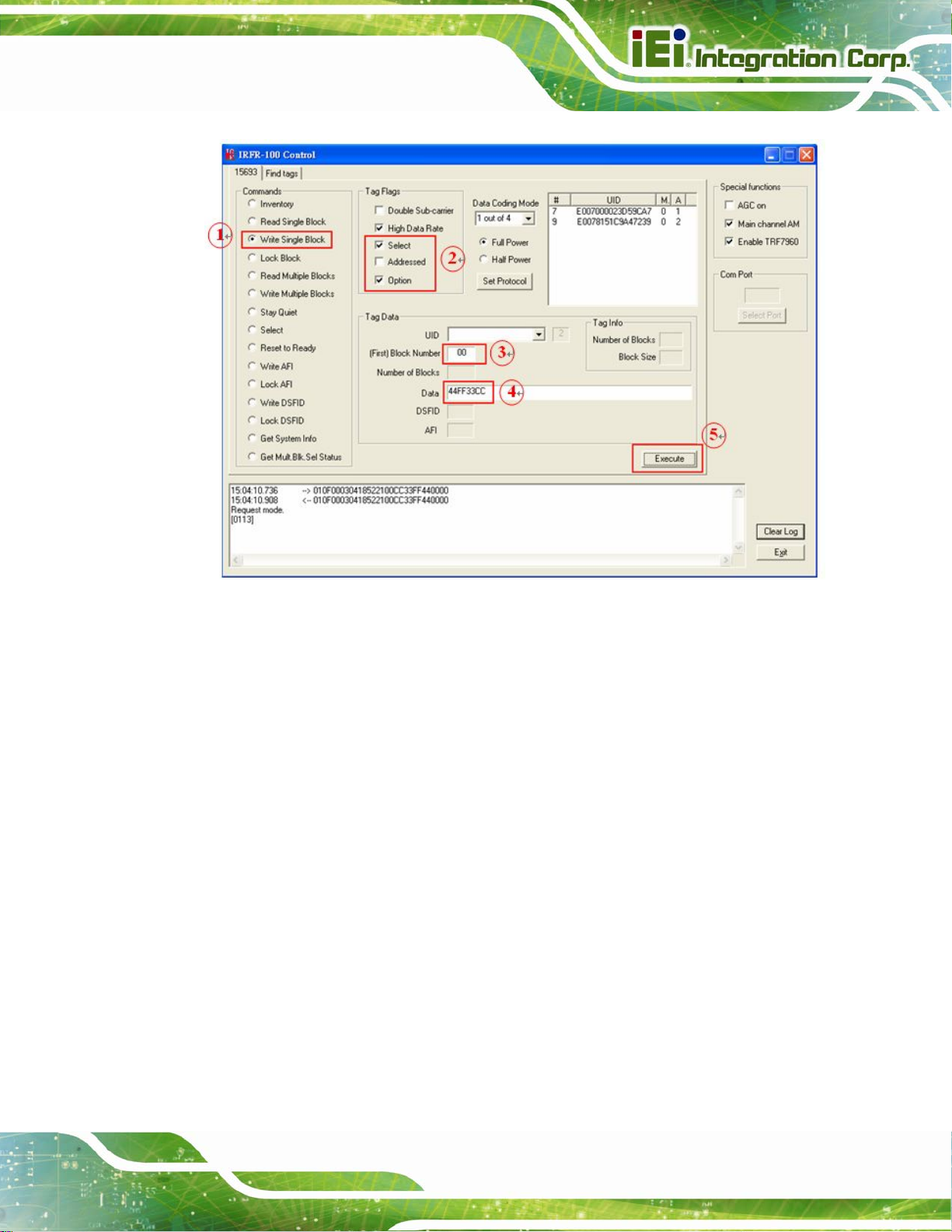
4.5.3 Write Single Block
The Write Single Block request writes data to one memory block of the addressed tag(s).
In order to successfully write data, the host must know the size of the memory block of the
tag. This information is available through the Get System Information request, if supported
by the tag. A corrupted response or lack of response from TRF7960 does not necessarily
indicate a failure to perform the write operation. Additionally, multiple transponders may
process a nonaddressed request. (See Appendix A for more instructions)
To write a single block, the user should:
Page 25
Page 36

Step 1: Click the button for Write Single Block in the Commands window
Step 2: Click on any flags that must be set in the Tag Flags window
Step 3: Optionally select a tag from the UID pulldown list in the Tag Data window and
set the Addressed flag (if only one tag is present, only one choice is available)
Step 4: Enter two hex digits corresponding to the block number in the (First) Block
Number field in the Tag Data window
Step 5: Enter 8 hexadecimal digits corresponding to the data to be written in the Data
field in the Tag Data window
Step 6: Execute the command Step 0:
AFL2-MF-RFID-KIT Series
Page 26
Figure 4-12: Write Single Block
Page 37

AFL2-MF-RFID-KIT Series
4.5.4 Lock Block
The Lock Block command write-protects one memory block of the addressed tag(s). A
corrupted response or lack of response from the TRF7960 does not necessarily indicate a
failure to perform the lock operation. Additionally, multiple transponders may process a
non-addressed request.
Used to permanently lock the requested block.
To lock a block, the user should:
Step 1: Click the button for Lock Block in the Command window
Step 2: Click on any flags that must be set in the Tag Flags window
Step 3: Optionally select a tag from the UID pulldown list in the Tag Data window and
set the Addressed flag (if only one tag is present, only one choice is available)
Step 4: Enter two hex digits corresponding to the block number in the (First) Block
Number field in the Tag Data window
Step 5: Execute the command Step 0:
Page 27
Page 38

AFL2-MF-RFID-KIT Series
Figure 4-13: Lock Block
NOTE:
The Option flag of the ISO 15693 defined Request flags must be set for
all Write and Lock commands to respond properly.
Page 28
Page 39

AFL2-MF-RFID-KIT Series
4.5.5 Read Multiple Blocks
The Read Multiple Blocks command gets the data from multiple memory blocks of the
responding tag. In addition to this data, a Block Security Status byte can be requested for
each block. This byte shows the write-protection of the block specified [e.g., unlocked,
(user/factory) locked, etc.].
To read multiple a blocks, the user should:
Step 1: Click the button for Read Multiple Blocks in the Commands window
Step 2: Click on any flags that must be set in the Tag Flags window
Step 3: Optionally select a tag from the UID pulldown list in the Tag Data window (if only
one tag is present, only one choice is available)
Step 4: Enter two hex digits corresponding to the starting block number in the (First)
Block Number field in the Tag Data window. The blocks are numbered from 00
to FF (0 to 255)
Step 5: Enter two hex digits corresponding to the number of blocks to be written in the
Number of Blocks field in the Tag Data window. The number of blocks in the
request is one less than the number of blocks that the tag returns in its respo nse
E.g., a value of 06 in the Number of Blocks field requests to read 7 blocks. A
value of 00 requests to read a single block
Step 6: Execute the command Step 0:
Page 29
Page 40

AFL2-MF-RFID-KIT Series
Figure 4-14: Read Multiple Blocks
4.5.6 Write Multiple Blocks
The Write Multiple Blocks command writes data to multiple memory blocks of the
addressed tags. In order to successfully write data, the host must know the size of the
memory block of the tag. Write Multiple Blocks is an optional command, and may not be
supported by the tag (see the following screen capture).
To write multiple blocks, the user should:
Step 1: Click the button for Write Multiple Blocks in the Commands window
Step 2: Click on any flags that must be set in the Tag Flags window
Step 3: Optionally select a tag from the UID pulldown list in the Tag Data window (if only
one tag is present, only one choice is available)
Page 30
Page 41

AFL2-MF-RFID-KIT Series
Step 4: Enter two hex digits corresponding to the starting block number in the (First)
Block Number field in the Tag Data window. The blocks are numbered from 00
to FF (0 to 255)
Step 5: Enter two hex digits corresponding to the number of blocks to be written in the
Number of Blocks field in the Tag Data window. The number of blocks in the
request is one less than the number of blocks that the tag returns in its respo nse
E.g., a value of 06 in the Number of Blocks field requests to read 7 blocks. A
value of 00 requests a read of a single block
Step 6: Enter hexadecimal digits corresponding to the data to be written in the Data field
in the Tag Data window
Step 7: Execute the commandStep 0:
Figure 4-15: Write Multiple Block
Page 31
Page 42
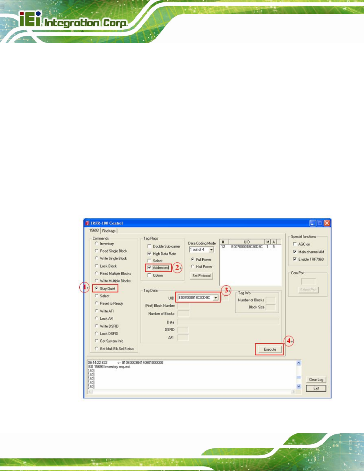
4.5.7 Stay Quiet
The Stay Quiet command is used to silence a tag, preventing it from responding to any
nonaddressed or inventory related commands. The tag does, however, respond to
requests with matching UID. As there is no response to this re quest from the recei ving tag,
only request status and errors are reported.
To command a tag to stay quiet, the user should:
Step 1: Click the button for Stay Quiet in the Commands window
Step 2: Click on any flags that must be set in the Tag Flags window
Step 3: Optionally select a tag from the UID pulldown list in the Tag Data window and
AFL2-MF-RFID-KIT Series
set the Addressed flag (if only one tag is present, only one choice is available)
Step 4: Execute the command Step 0:
Page 32
Figure 4-16: Stay Quiet
Page 43

AFL2-MF-RFID-KIT Series
If you want to clear Quiet mode, see following instructions:
Step 1: Click the button for Reset to Ready in the Commands window
Step 2: Click on addressed flag in the Tag Flags window
Step 3: Select a tag which is in Quiet mode from the UID pulldown list in the Tag Data
window
Step 4: Execute the command Step 0:
At last, the tag will response to any nonaddressed or inventory related commands.
4.5.8 Select
The Select command places the addressed tag in the Select state. In this state, it
responds to requests with the ISO 15693 Select Flag set. This flag is directly controlled by
the <IsSelectMsg> field present in many ISO 15693 library request messages. Any
receiving tag currently in the Select state with UID not matching the value sent in the
request command, exits that state and enters the Ready state but does not send a reply.
(See Appendix A for more instructions)
To select a tag, the user should:
Step 1: Click the button for Select in the Commands window
Step 2: Click on any flags that must be set in the Tag Flags window
Step 3: Optionally select a tag from the UID pulldown list in the Tag Data window and
set the Addressed flag (if only one tag is present, only one choice is available)
Step 4: Execute the command Step 0:
Page 33
Page 44

AFL2-MF-RFID-KIT Series
Figure 4-17: Select
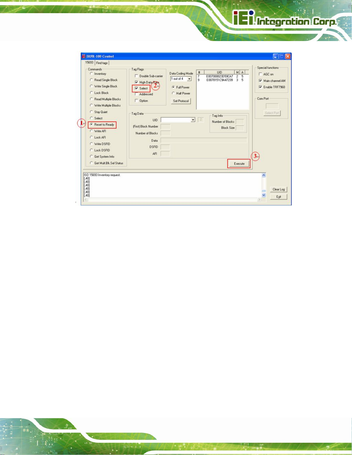
4.5.9 Reset to Ready
The Reset To Ready command places the addressed tag in the Ready state. In this state,
it does not respond to requests with the ISO 15693 Select Tag Flags set, but to any
nonaddressed request or request matching its UID.
This command is, in effect, the complement of the Select command, and undoes it.
To reset a tag, the user should:
Step 1: Click the button for Reset to Ready in the Commands window
Step 2: Click on any flags that must be set in the Tag Flags window
Step 3: Optionally select a tag from the UID pulldown list in the Tag Data window (if only
one tag is present, only one choice is available)
Page 34
Step 4: Execute the command Step 0:
Page 45

AFL2-MF-RFID-KIT Series
Figure 4-18: Reset to Ready
4.5.10 Write AFI (Application Family Identifier)
The Write AFI command records a new value to the AFI register (see Appendix B for AFI
codes) of the addressed tag(s) . A corrupted respons e or lack of respons e from TRF7960
does not necessarily indicate a failure to perform the write operation. Additionally, multiple
transponders may process a non-addressed request.
AFI represents the tag application, and is used to extract information from tags meeting
the application criteria.
To write a tag’s AFI, the user should:
Step 1: Click the button for Write AFI in the Commands window
Step 2: Click on any flags that must be set in the Tag Flags window
Page 35
Page 46
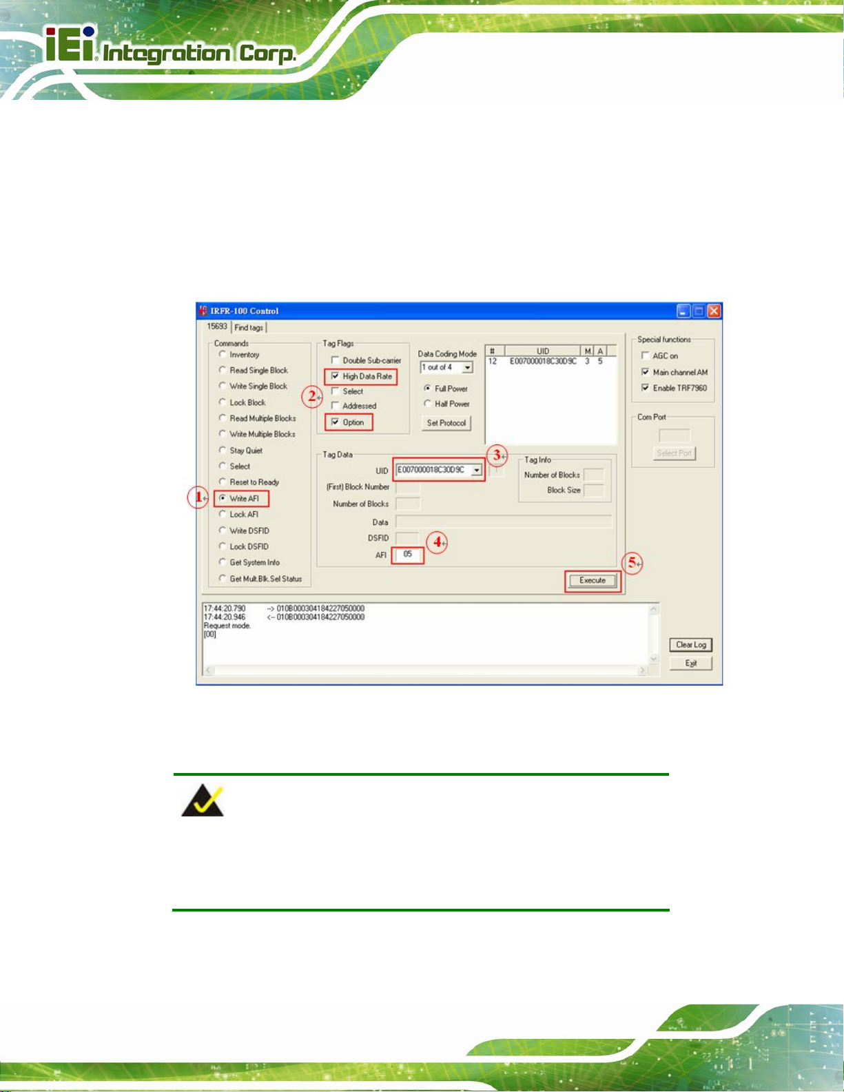
Step 3: Optionally select a tag from the UID pulldown list in the Tag Data window (if only
one tag is present only one choice is available)
Step 4: Enter the desired AFI code in the AFI field in the Tag Data window (in
hexadecimal)
Step 5: Execute the command Step 0:
AFL2-MF-RFID-KIT Series
Page 36
Figure 4-19: Write AFI
NOTE:
The Option flag (bit 7) of the ISO 15693 defined Request flags must be
set to 1 for all Write and Lock commands to respond properly.
Page 47
AFL2-MF-RFID-KIT Series
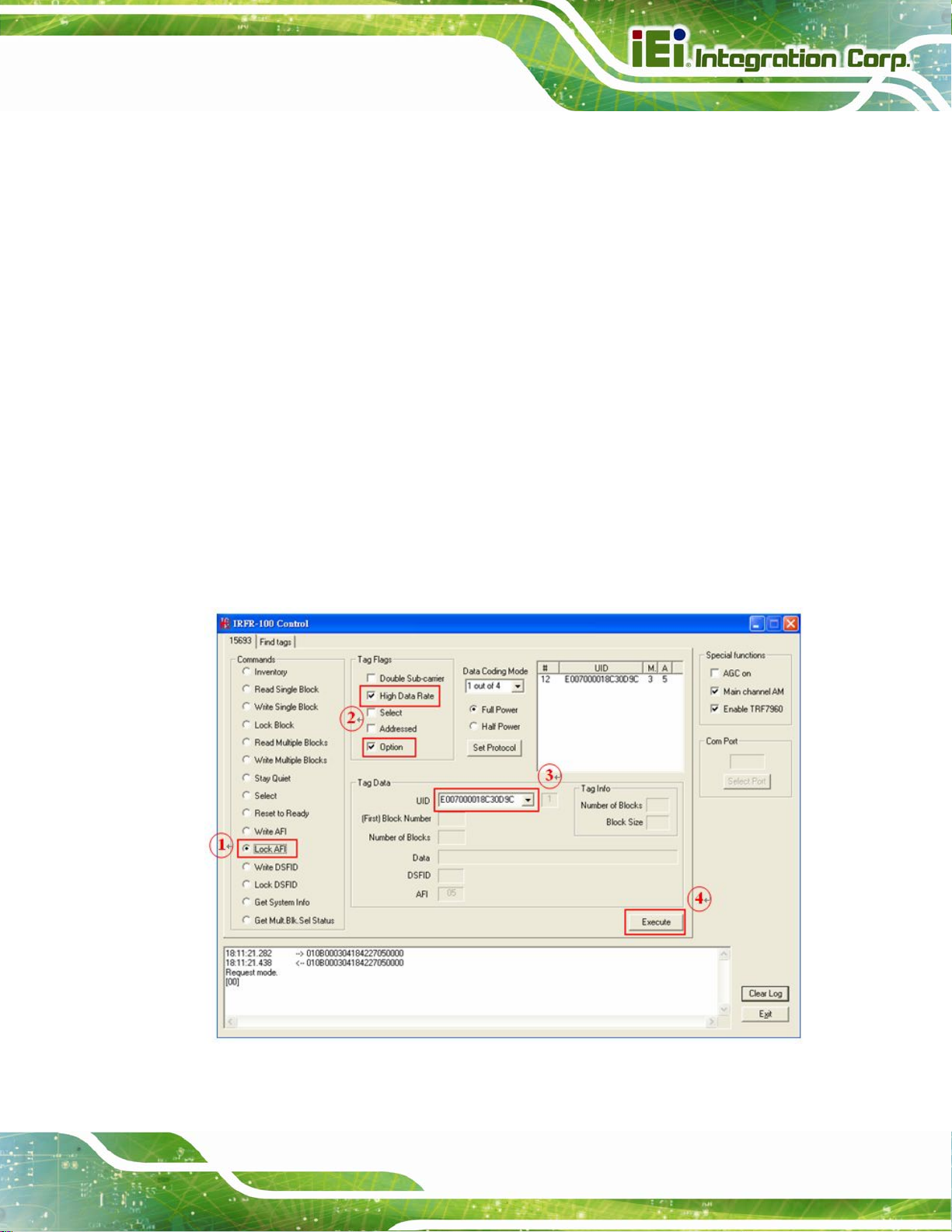
4.5.11 Lock AFI (Application Family Identifier)
The Lock AFI command write-protects the AFI register of the addressed tag(s). A
corrupted response or lack of response does not necessarily indicate a failure to perform
the lock operation. Additionally, multiple transponders may process a nonaddressed
request.
Used to permanently lock the AFI.
To a lock tag’s AFI, the user should:
Step 1: Click the button for Lock AFI in the Commands window
Step 2: Click on any flags that must be set in the Tag Flags window
Step 3: Optionally select a tag from the UID pulldown list in the Tag Data window (if only
one tag is present, only one choice is available)
Step 4: Execute the command Step 0:
Figure 4-20: Lock AFI
Page 37
Page 48

NOTE:
The Option flag (bit 7) of the ISO 15693 defined Request flags must be
set to 1 for all Write and Lock commands to respond properly.
4.5.12 Write DSFID (Data Storage Format ID)
The Write DSFID (data storage format ID) command writes a new value in the DSFID
register of the addressed tag(s). A corrupted response or lack of response from the
TRF7960 does not necessarily indicate a failure to perform the write operation.
Additionally, multiple transponders may process a nonaddressed request.
To write a tag’s DSFID, the user should:
AFL2-MF-RFID-KIT Series
Step 1: Click the button for Write DSFID in the Commands Window
Step 2: Click on any flags that must be set in the Tag Flags window
Step 3: Select a tag from the UID pulldown list in the Tag Data window (if only one tag is
present, only one choice is available)
Step 4: Enter the desired DSFID code in the DSFID field in the Tag Data window (in
hexadecimal)
Step 5: Execute the command Step 0:
Page 38
Page 49

AFL2-MF-RFID-KIT Series
Figure 4-21: Write DSFID
NOTE:
The Option flag (bit 7) of the ISO 15693 defined Request flags must be
set to 1 for all Write and Lock commands to respond properly.
4.5.13 Lock DSFID (Data Storage Format ID)
The Lock DSFID command write-protects the DSFID register of the addressed tag(s). A
corrupted response or lack of response from TRF7960 does not necessarily indicate a
failure to perform the lock operation. Additionally, multiple transponders may process a
nonaddressed request.
Used to permanently lock the DSFID.
To a lock tag’s DSFID, the user should:
Page 39
Page 50

Step 1: Click the button for Lock DSFID in the Commands window
Step 2: Click on any flags that must be set in the Tag Flags window
Step 3: Optionally select a tag from the UID pulldown list in the Tag Data window (if only
one tag is present, only one choice is available)
Step 4: Execute the command Step 0:
AFL2-MF-RFID-KIT Series
Page 40
Figure 4-22: Lock DSFID
NOTE:
The Option flag (bit 7) of the ISO 15693 defined Request flags must be
set to 1 for all Write and Lock commands to respond properly.
Page 51

AFL2-MF-RFID-KIT Series
4.5.14 Get System Info
The Get System Info command retrieves identification, application family, data formatting,
and memory block sizes as specified in the ISO 15693 standard (if tag supports this
command).
To get system information, the user should:
Step 1: Click the button for Get System Info in the Commands window
Step 2: Click on any flags that must be set in the Tag Flags window
Step 3: Optionally select a tag from the UID pulldown list in the Tag Data window (if only
one tag is present, only one choice is available)
Step 4: Execute the command Step 0:
Figure 4-23: Get System Info
Page 41
Page 52

AFL2-MF-RFID-KIT Series
4.5.15 Get Multiple-Block Security Status (Get Mult_Blk Sel Status)
The Get Multiple-Block Security Status (Get Mutt. Blk. Sel Status) command gets a block
security status byte for each block requested. This byte encodes the write protection of the
block specified (e.g., unlocked, (user/factory) locked, etc.).
To get multiple block security status, the user should:
Step 1: Click the button for Get Mult.Blk.Sel Status in the Commands window
Step 2: Click on any flags that must be set in the Tag Flags window
Step 3: Optionally select a tag from the UID pulldown list in the Tag Data window (if only
one tag is present, only one choice is available)
Step 4: Enter two hex digits corresponding to the starting block number in the (First)
Block Number field in the Tag Data window. The blocks are numbered from 00
to FF (0 to 255)
Step 5: Enter two hex digits corresponding to the number of blocks to be written in the
Number of Blocks field in the Tag Data window. The number of blocks in the
request is one less than the number of blocks that the tag returns in its respo nse
E.g., a value of 06 in the Number of Blocks field requests to read 7 blocks. A
value of 00 requests to read a single block
Step 6: Execute the command Step 0:
Page 42
Page 53

AFL2-MF-RFID-KIT Series
Figure 4-24: Get Multiple-Block Security Status
Page 43
Page 54

4.6 Find Tags
The Find tags window enables the query of the RF field for all supported tags. It
continuously sends an Inventory request and displays all the tag labels found within the
read range of the reader. The user can select the appropriate buttons that correspond to
the protocol field.
AFL2-MF-RFID-KIT Series
Page 44
Figure 4-25:
Once the Run button is clicked, the window shows all tags found within its reception area.
This command runs until the Stop button is clicked (shared location with the Run button).
An indicator for the supported standards is active when the particular protocol is running.
This moving right cursor can be found located left of the Select All button.
This command is recommended for demonstrations, as it requires no specific knowledge
of commands/flags for each protocol.
Page 55

AFL2-MF-RFID-KIT Series
Appendix
A
A Multiple Tags
Writing Instruction
Page 45
Page 56

A.1 Inventory Request
With the Inventory request, all the UIDs from the tags in the reader field are displayed.
AFL2-MF-RFID-KIT Series
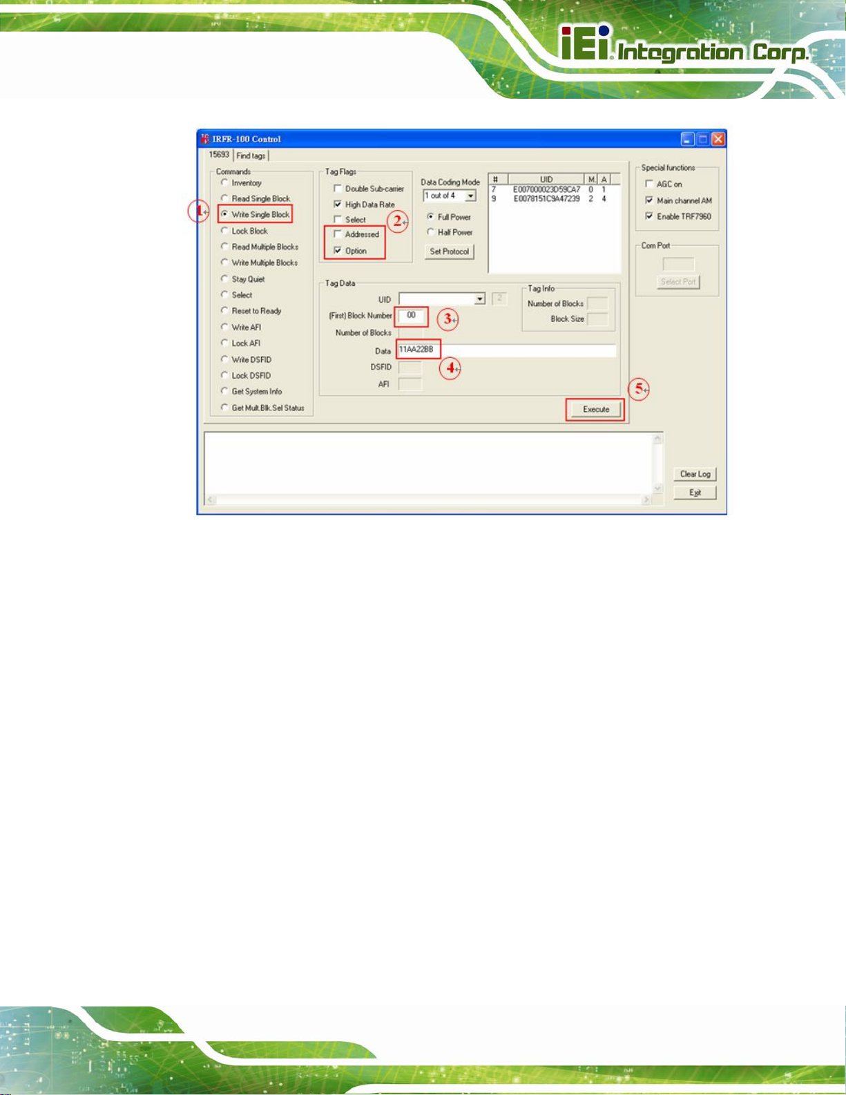
A.2 NON - ADDRESSED Mode
In NON-ADDRESSED mode, users can write data to multiple tags at one time.
Needn’t choosing the UID of the tag
Un-check the 'Addressed' flag
Check the 'Option' flag
Page 46
Page 57
AFL2-MF-RFID-KIT Series
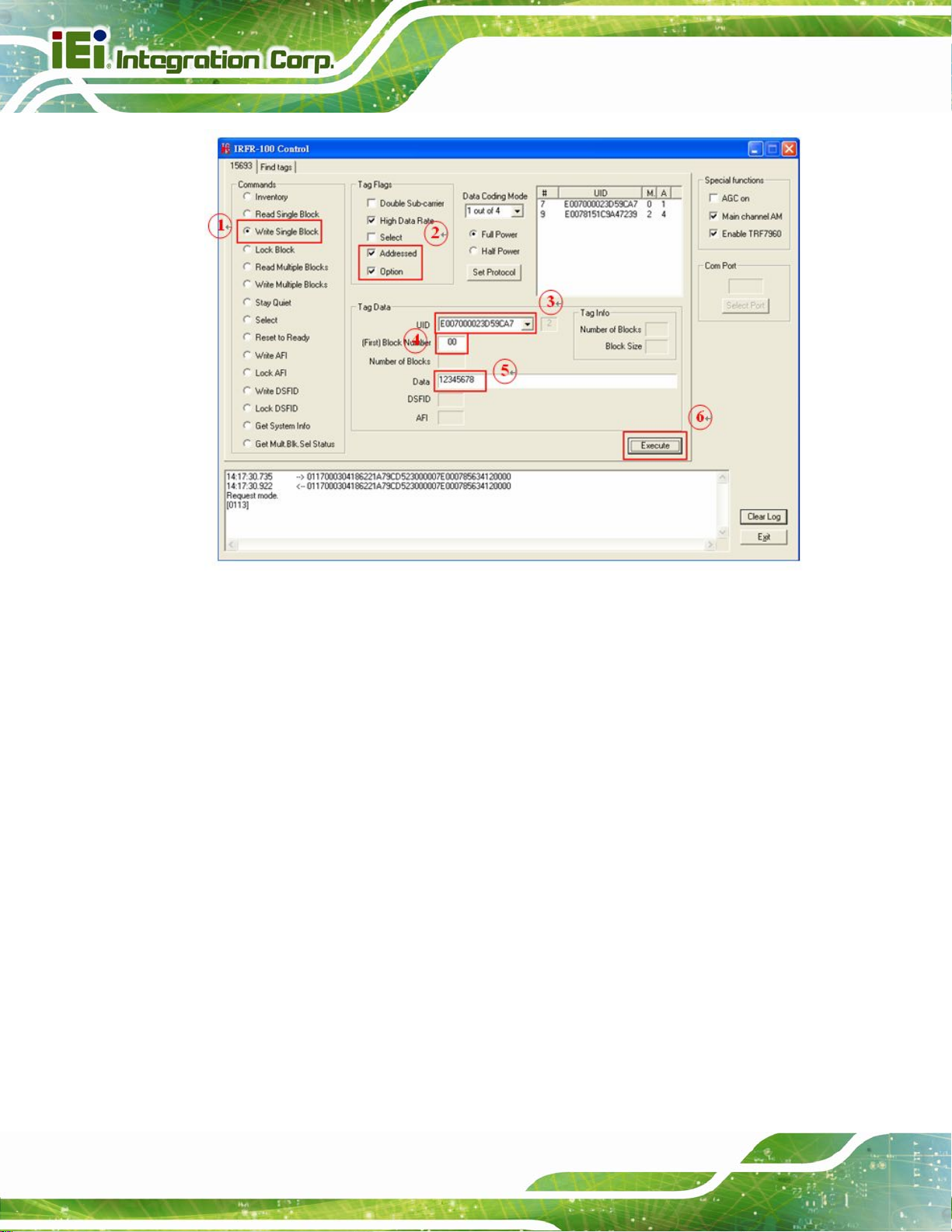
A.3 ADDRESSED Mode
In ADDRESSED mode, you can write data to a specific tag.
Choose the UID of the tag
Check the 'Addressed' flag
Check the 'Option' flag
Page 47
Page 58
AFL2-MF-RFID-KIT Series
Reading back the written data from a specific tag:
The 'Addressed' flag has to be selected
The 'Option' flag is optional
If the “Option” flag is set, then the last two digits (when a Read single block is executed)
will designate whether the tag is unlocked (00) or locked (01)):
Page 48
Page 59

AFL2-MF-RFID-KIT Series
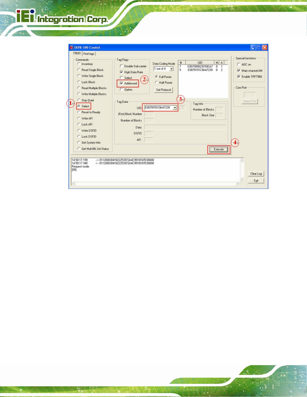
A.4 SELECTED Mode
Setting a tag in selected state:
Choose 'Select' command
The 'Addressed' flag has to be set
Choose the UID of the preferred tag
Page 49
Page 60
AFL2-MF-RFID-KIT Series
When a tag is set in selected state, all other requests will not need to choose its UID.
Writing data to a tag, which is in selected state:
The 'Select' flag has to be set
Check the 'Option' flag
Page 50
Page 61
AFL2-MF-RFID-KIT Series
Reading data from a selected tag:
The 'Select' flag has to be set
Page 51
Page 62
AFL2-MF-RFID-KIT Series
If we want to select the second tag, the first tag (the one in the selected state) has to be
deselected first.
To deselect the first tag:
The 'Select' flag has to be set
Page 52
Page 63
AFL2-MF-RFID-KIT Series
Setting the second tag in selected state, please return to follow the steps of A.4.
Page 53
Page 64

AFL2-MF-RFID-KIT Series
Appendix
B
B TestDII Program
Page 54
Page 65

AFL2-MF-RFID-KIT Series
B.1 Introduction
This document provides the information for application developer to understand the
IRFR-100 - TestDll Program architecture and application programming reference. The
demo program is developed by using Microsoft Visual Studio .NET 2003. MFC library. And
the demo program for WinCE is developed by Microsoft eMbedded Visual C++ 4.0 MFC
library.
B.2 How to use
Before you can utilize the IRFR-100 software application programming interface, you have
to do some basic initialization. The SDK package includes one dynamic link library named
“IRFR_100_DLL.dll”. You need to include “IRFR_100_DLL.h” in y our appli cation header file
and set “IRFR_100_DLL.lib” in project linker input, then you can use its APIs.
IRFR_100_TestDll_C.rar will demonstrate how to use IRFR_100_DLL_C library.
IRFR-100-TestDll Application Architecture :
Page 55
Page 66

AFL2-MF-RFID-KIT Series
B.3 Tag Information Structure
The data structure contains all information about RFID Tag. Below are the declarations of
TagFlag, TagData, TagInfo, RSSI and the description of entries.
B.3.1 Tag Flag
struct tagflag {
int t15CodingMode;
int t15bSubCarrier;
int t15bDataRate;
int t15bInventory;
int t15bSelect;
int t15bAddress;
int t15bOption;
int t15iFullPower;
};
typedef struct tagflag TagFlag;
Variable
Value = 0 Value = 1
t15CodingMode 1 out of 4 1 out of 256
t15bSubCarrier single sub-carrier double sub-carrier
t15bDataRate low data rate high data rate
t15bInventory other request inventory request
t15bSelect disable select mode enable select mode
t15bAddress non-addressed mode addressed mode
t15bOption disable option enable option
t15iFullPower full power half power
Description
B.3.2 Tag Data
Struct tagdata{
Page 56
Page 67

AFL2-MF-RFID-KIT Series
char t15UID [CMD_LEN];
char t15FirstBN [HEX_LEN];
char t15NumBl [HEX_LEN];
char t15Data [CMD_LEN];
char t15DSFID [DSFID_LEN];
char t15AFI [HEX_LEN];
};
typedef struct tagdata TagData;
Variable Description
t15UID Tag UID CMD_LEN = 2048
t15FirstBN First block number HEX_LEN = 4
t15NumBl Number of Blocks HEX_LEN = 4
t15Data Block data CMD_LEN = 2048
t15DSFID DSFID number DSFID_LEN = 4
t15AFI AFI number HEX_LEN = 4
B.3.3 Tag Info
struct taginfo{
char DSFID [DSFID_LEN];
char AFI [HEX_LEN];
char NumofBlk [HEX_LEN];
char BlkSize [HEX_LEN];
};
typedef struct taginfo TagInfo;
Variable Description
DSFID DSFID number DSFID_LEN = 4
AFI AFI number HEX_LEN = 4
NumofBlk Number of Blocks HEX_LEN = 4
Page 57
Page 68

BlkSize Block size HEX_LEN = 4
AFL2-MF-RFID-KIT Series
B.3.4 RSSI
struct rssi{
char Slot [BUF_LEN];
char UID [CMD_LEN];
char AM [BUF_LEN];
char PM [BUF_LEN];
};
typedef struct rssi RSSI;
Variable Description
Slot Slot number (1 ~ 16) BUF_LEN = 36
UID Tag UID CMD_LEN = 2048
AM Main channel BUF_LEN = 36
PM Sub channel BUF_LEN = 36
B.3.5 Request Command Type
These are definitions of request command type used by IRFR_RequestExecute()
function
#define INVENTORY 0
#define READ_SB 1
#define WRITE_SB 2
#define LOCK_B 3
#define READ_MB 4
#define WRITE_MB 5
#define QUIET 6
#define SELECT 7
#define READY 8
Page 58
#define WRITE_AFI 9
#define LOCK_AFI 10
#define WRITE_DSFID 11
#define LOCK_DSFID 12
Page 69

AFL2-MF-RFID-KIT Series
#define SYSTEM_INFO 13
#define MBS_STATUS 14
B.4 Software APIs
BOOL IRFR_FindPort ( void )
This function can be used to find com port and open it automatically.
[ Parameter ]
None.
[ Return ]
If open IRFR-100 device com port succes sfully, it return 1, otherwise return 0.
Example :
IRFR_FindPort ();
BOOL IRFR_FindSinglePort ( char * Port )
This function can be used to open com port manually.
[ Parameter ]
char * Port : assign IRFR-100 device com port name.
[ Return ]
If open IRFR-100 device com port successfully, it return 1, otherwise return 0.
Example :
XP/Vista : BOOL IRFR_FindSinglePort ( "COM4" );
WinCE: BOOL IRFR_FindSinglePort ( "COM4:" );
Page 59
Page 70

AFL2-MF-RFID-KIT Series
int IRFR_logAddFile ( char * msg )
This function can be used to write string to user defined log file. Remember to call
IRFR_SetFilePath() to set log file pathname first.
[ Parameter ]
char * msg : assign user defined string.
[ Return ]
If write string successfully, it return 0, otherwise return 1 (NULL_FILE_PATH ).
Example :
IRFR_logAddFile ( “Com Port Found!!” );
Int IRFR_logAddScreen ( char * msg )
This function can be used to write string to user defined MFC CEdit control variable and show it
on the screen. Remember to call IRFR_SetLogger() to set CEdit control variable first.
[ Parameter ]
char * msg : assign user defined string.
[ Return ]
If write string successfully, it return 0, otherwise return 2 (NULL_LOGGER ).
Example :
IRFR_logAddScreen ( “Com Port Found!!” );
void IRFR_SetFilePath ( char * path )
This function can be used to set log file pathname.
[ Parameter ]
char * path : assign user defined file pathname.
[ Return ]
Page 60
Page 71

AFL2-MF-RFID-KIT Series
None.
Example :
IRFR_SetFilePath ( "TestDll.log" );
void IRFR_SetLogger ( CEdit *logger )
This function can be used to set MFC CEdit control variable.
[ Parameter ]
CEdit *logger : assign user defined CEdit control variable.
[ Return ]
None.
Example :
IRFR_SetLogger ( &m_myLogger );
void IRFR_SetLogFile ( bool result )
This function can be used to enable or disable log to file feature.
[ Parameter ]
bool result : assign true to enable log to file feature, or false to disable it.
[ Return ]
None.
Example :
IRFR_SetLogFile ( false );
Page 61
Page 72

AFL2-MF-RFID-KIT Series
void IRFR_SetLogScreen ( bool result )
This function can be used to enable or disable log to screen feature.
[ Parameter ]
bool result : assign true to enable log to screen feature, or false to disable it.
[ Return ]
None.
Example :
IRFR_SetLogScreen ( false );
void IRFR_ClearLog ( void );
This function can be used to clear CEdit control variable buffer and clear screen data.
[ Parameter ]
None.
[ Return ]
None.
Example :
IRFR_ClearLog ();
int IRFR_SetProtocol ( TagFlag tf );
This function can be used to set or update operation flags of IRFR-100 device.
[ Parameter ]
TagFlag tf : assign user defined TagFlag structure.
[ Return ]
If success, return 0, otherwise return 1.
Example :
Page 62
Page 73

AFL2-MF-RFID-KIT Series
m_tf -> t15CodingMode = 0; // 1 out of 4
m_tf -> t15bSubCarrier = 0; // single sub carrier
m_tf -> t15bDataRate = 1; // high data rate
m_tf -> t15bInventory = 1; // inventory request
m_tf -> t15bSelect = 0; // disable select mode
m_tf -> t15bAddress = 0; // non-addressed mode
m_tf -> t15bOption = 0; // disable option
m_tf -> t15iFullPower = 0; // 0:enable full power, 1:half power
IRFR_SetProtocol ( *m_tf );
int IRFR_RequestExecute ( int cmdno, char *reply, TagFlag tf, TagData
*td )
This function can be used to execute request command of ISO 15693. And IRFR-100 response
data will be saved in reply buffer.
[ Parameter ]
int cmdno : assign request command type.
char *reply : assign user defined buffer to save data responded from IRFR-100
device.
TagFlag tf : assign user defined TagFlag structure.
TagData *td : assign user defined TagData structure.
[ Return ]
If success, return 0, otherwise return 1.
Example :
IRFR_RequestExecute ( INVENTORY, m_reply, *m_tf, m_td );
void IRFR_FindRun ( char *TagIDs, char *TagNum )
This function can be used to find the UIDs of all tags (only ISO 15693 support) in the Antenna
area automatically.
[ Parameter ]
char *TagIDs : assign user defined buffer to save all Tags UIDs.
Page 63
Page 74

char *TagNum : assign user defined buffer to save Tag number.
[ Return ]
None.
Example :
IRFR_FindRun ( m_TagIDs, m_TagNum );
AFL2-MF-RFID-KIT Series
void IRFR_FindStop ( void )
This function can be used to stop finding Tags.
[ Parameter ]
None.
[ Return ]
None.
Example :
IRFR_FindStop ();
void IRFR_GetUIDs ( char *reply, char *TagIDs[ ], char *TagNum )
This function can be used to parse the given reply buffer to retrieve Tag UIDs and Tag number.
[ Parameter ]
char *reply : assign reply buffer which contains responded data from IRFR-100
device.
char *TagIDs[ ] : assign user defined buffer to save all Tags UIDs.
char *TagNum : assign user defined buffer to save Tag number.
[ Return ]
None.
Example :
Page 64
Page 75

AFL2-MF-RFID-KIT Series
IRFR_GetUIDs ( m_reply, TagIDs, TagNum );
Remember to call IRFR_RequestExecute ( INVENTORY, m_reply, *m_tf, m_td ) first to get all
tags information from IRFR-100 device and save them in the reply buffer.
void IRFR_GetRSSI ( char *reply, RSSI RSSIs[ ] )
This function can be used to parse the given reply buffer to retrieve RSSI information.
[ Parameter ]
char *reply : assign reply buffer which contains responded data from IRFR-100 device.
RSSI RSSIs[ ] : assign user defined RSSI structure to save all Tags RSSI info.
[ Return ]
None.
Example :
IRFR_GetRSSI ( m_reply, RSSIs );
Remember to call IRFR_RequestExecute ( INVENTORY, m_reply, *m_tf, m_td ) first to get all
tags information from IRFR-100 device and save them in the reply buffer.
void IRFR_GetBlockData ( char *reply, TagData *td )
This function can be used to parse the given reply buffer to retrieve single block data of
specified block index.
[ Parameter ]
char *reply : assign reply buffer which contains responded data from IRFR-100 device.
TagData *td : assign user defined TagData structure to save block data.
[ Return ]
None.
Example :
IRFR_GetBlockData ( m_reply, m_td );
Page 65
Page 76

Remember to call IRFR_RequestExecute ( READ_SB, m_reply, *m_tf, m_td ) first to get
specified tag information from IRFR-100 device and save them in the reply buffer.
AFL2-MF-RFID-KIT Series
void IRFR_GetMultiBlockData ( char *reply, TagData *td );
This function can be used to parse the given reply buffer to retrieve multiple block data of
specified block index range.
[ Parameter ]
char *reply : assign reply buffer which contains responded data from IRFR-100 device.
TagData *td : assign user defined TagData structure to save multiple block data.
[ Return ]
None.
Example :
IRFR_GetMultiBlockData ( m_reply, m_td );
Remember to call IRFR_RequestExecute ( READ_MB, m_reply, *m_tf, m_td ) first to get
specified tag information from IRFR-100 device and save them in the reply buffer.
void IRFR_GetTagInfo ( char *reply, TagInfo *ti, TagFlag tf, TagData td )
This function can be used to parse the given reply buffer to retrieve total block number and
block size of specified tag.
[ Parameter ]
char *reply : assign user defined buffer to save data responded from IRFR-100
device.
TagInfo *ti : assign user defifned TagInfo structure to save tag information.
TagFlag tf : assign user defined TagFlag structure.
TagData *td : assign user defined TagData structure.
[ Return ]
None.
Page 66
Page 77

AFL2-MF-RFID-KIT Series
Example :
IRFR_GetTagInfo ( m_reply, m_ti, *m_tf, *m_td );
Remember to call IRFR_RequestExecute ( SYSTEM_INFO, m_reply, *m_tf, m_td )
first to get
specified tag information from IRFR-100 device and save them in the reply buffer.
void IRFR_GetMultiBlockSecurity ( char *reply, char *SecurityData )
This function can be used to parse the given reply buffer to retrieve the status (lock or unlock) of
multiple blocks.
[ Parameter ]
char *reply : assign reply buffer which contains responded data from IRFR-100 device.
char *SecurityData : assign user defined buffer to save the status of multiple blocks.
[ Return ]
None.
Example :
IRFR_GetMultiBlockSecurity ( m_reply, m_SecurityData );
Remember to call IRFR_RequestExecute ( MBS_STATUS, m_reply, *m_tf, m_td ) first to get
specified tag information from IRFR-100 device and save them in the reply buffer.
B.5 Example Code
Please extract IRFR_100_TestDll_C.rar (XP/Vista) or IRFR_100_TestDll_MFC_CE.rar
(WinCE) in the “IRFR-100 APPLICATION SDK” package and uncomment one of section
B.4 and build the project to show the demo application.
Page 67
Page 78

AFL2-MF-RFID-KIT Series
Appendix
C
C ISO/IEC 15693
Reference Material
Page 68
Page 79

AFL2-MF-RFID-KIT Series
C.1 UID Format
The tags are uniquely identified by a 64-bit unique identifier (UID). This is used for
addressing each tag uniquely and individually during the anticollisi on loop, and for
one-to-one exchange between a reader and a tag.
The format of the UID is shown below:
Bits 64 to 57 Bits 56 to 49 Bits 48 to 1
E0 Manufacturer code IC serial number
The UID is composed of:
The 8 MSBs, which are E0.
The 8-bit IC manufacturer code
A unique serial number of 48 bits assigned by the IC manufacturer
C.2 Tag Memory Organization
Tag memory is organized into blocks of bytes. Addressing is by block only. There is no
individual byte addressing for read or write; the whole block i s accessed. It is an alogou s to
a spreadsheet with rows and columns, where addressing accesses a whole row at once.
The format of tag memory is shown as follows:
Bits 16 to 14 Bits 13 to 9 Bits 8 to 1
RFU Block size in bytes Number of blocks
Block size is expressed in 5 bits, allowing up to 32 bytes, i.e., 256 bits. It is one less
than the actual number of bytes. E.g., a value of 1F indicates 32 bytes; a value of 00
indicates 1 byte.
Number of blocks is defined in 8 bits, allowing up to 256 blocks. It is one less than the
actual number of blocks. E.g., a value of FF indicates 256 blocks; a value of 00
indicates 1 block.
The 3 most-significant bits are reserved for future use and are set to zero.
This addressing scheme limits the total storage of the tag to 8K bytes.
Page 69
Page 80

C.3 Flag Definitions
High Data Rate: the default data rate is used for maximum detection range. If High
Data Rate is selected in the Tag Flags window, communication with the tag is faster,
but the range is reduced.
AFI is present: The default setting for the AFI (Application Family Identifier) is off. If
AFI is present is selected in the Tag Flags window, AFI is enabled in commands and
responses.
One Slot: the definition of slot, as used in the software, is the number of tags that may
be received at a time. The default is 16. If only One Slot is selected in the Tag Flags
window, the algorithm detects a flag sooner, but stops after detecting the first tag.
Other tags in the reception range of the reader are ignored.
Select: the default is off. Request executed by any tag according to the setting of
Addressed flag. If select flag is selected in the Tag Flags window, request executed
only by tag in selected state. The Addressed flag is set to 0 and the UID field is not
AFL2-MF-RFID-KIT Series
included in the request.
Addressed: the default setting is off. Request is not addressed. UID field is not
included. It can be executed by any tag. If addressed flag is selected in the Tag Flags
window, request is addressed. UID field is included. It is executed only by the tag
whose UID matches the UID specified in the request.
Option: Meaning is defined by the command description.
C.4 Application Family Identifier (AFI) Definitions
AFI Most Significant
Nibble
0 0 All families and subfamilies No applicable reselection
X 0 All subfamilies of family X Wide applicable
X Y Only the Yth subfamily of family X
AFI Least Significant
Nibble
Meaning Tags Respond From Examples/Note
preselection
Page 70
0 Y Proprietary subfamily Y only
1 0, Y Transport Mass transit, bus, airline
2 0, Y Financial IEP, banking, retail
Page 81

AFL2-MF-RFID-KIT Series
3 0, Y Identification Access control
4 0, Y Telecommunication Public telephony, GSM
5 0, Y Medical
6 0, Y Multimedia Internet services
7 0, Y Gaming
8 0, Y Data storage Portable files
9 0, Y Item management
A 0, Y Express parcels
B 0, Y Postal services
C 0, Y Airline bags
D 0, Y RFU Reserved for future use
E 0, Y RFU Reserved for future use
F 0, Y RFU Reserved for future use
Page 71
Page 82

AFL2-MF-RFID-KIT Series
Appendix
D
D Hazardous Materials
Disclosure
Page 72
Page 83

AFL2-MF-RFID-KIT Series
D.1 Hazardous Materials Disclosure Table for IPB Products
Certified as RoHS Compliant Under 2002/95/EC Without
Mercury
The details provided in this appendix are to ensure that the product is compliant with the
Peoples Republic of China (China) RoHS standards. The table below acknowledges the
presences of small quantities of certain materials in the product, and is appli cable to China
RoHS only.
A label will be placed on each product to indicate the estimated “Environmentally Friendly
Use Period” (EFUP). This is an estimate of the number of years that these substances
would “not leak out or undergo abrupt change.” This product may contain replaceable
sub-assemblies/components which have a shorter EFUP such as batteries and lamps.
These components will be separately marked.
Please refer to the table on the next page.
Page 73
Page 84

Toxic or Hazardous Substances and Elements Part Name
AFL2-MF-RFID-KIT Series
Housing
Display
Printed Circuit
Board
Metal
Fasteners
Cable
Assembly
Fan Assembly
Power Supply
Assemblies
Lead
(Pb)
O O O O O O
O O O O O O
O O O O O O
O O O O O O
O O O O O O
O O O O O O
O O O O O O
Mercury
(Hg)
Cadmium
(Cd)
Hexavalent
Chromium
(CR(VI))
Polybrominated
Biphenyls
(PBB)
Polybrominated
Diphenyl
Ethers
(PBDE)
Battery
O: This toxic or hazardous substance is contained in all of the homogeneous materials for the part is
below the limit requirement in SJ/T11363-2006
X: This toxic or hazardous substance is contained in at least one of the homogeneo us mate rials for
this part is above the limit requirement in SJ/T11363-2006
O O O O O O
Page 74
Page 85

AFL2-MF-RFID-KIT Series
此附件旨在确保本产品符合中国 RoHS 标准。以下表格标示此产品中某有毒物质的含量符
合中国 RoHS标准规定的限量要求。
本产品上会附有”环境友好使用期限”的标签,此期限是估算这些物质”不会有泄漏或突变”的
年限。本产品可能包含有较短的环境友好使用期限的可替换元件,像是电池或灯管,这些元
件将会单独标示出来。
部件名称
壳体
显示
印刷电路板
金属螺帽
电缆组装
风扇组装
电力供应组装
电池
O: 表示该有毒有害物质在该部件所有物质材料中的含量均在 SJ/T11363-2006 标准规定的限量要求以下。
X: 表示该有毒有害物质至少在该部件的某一均质材料中的含量超出 SJ/T11363-2006 标准规定的限量要求。
有毒有害物质或元素
铅
(Pb)
O O O O O O
O O O O O O
O O O O O O
O O O O O O
O O O O O O
O O O O O O
O O O O O O
O O O O O O
汞
(Hg)
镉
(Cd)
六价铬
(CR(VI))
多溴联苯
(PBB)
多溴二苯
醚
(PBDE)
Page 75
 Loading...