

Page 1

AFL2-EM-RFID-KIT01
Page i
MODEL:
EM RFID reader, 125K Hz, w/o LED indicator, for
Rev. 1.00 – 17 April, 2014
IRFD-210 RFID Reader
AFL2-EM-RFID-KIT
AFL2-W07A/ 08A/ 10A/W 10A/ 12A/ 15 A/ W 15B/ 17A/W 19A Series ,
IEI As s em bly Only, R10
User Manual
Page 2

AFL2-EM-RFID-KIT01
Page ii
Date Version Changes
17 April, 2014 1.00 Initial release
Revision
Page 3

AFL2-EM-RFID-KIT01
Page iii
Copyright
COP YRIGHT NOTICE
The information in this document is subject to change without prior notice in order to
improve reliabilit y, design and func tion and does not represent a com mitm ent on the par t
of the manufacturer.
In no event will the manufacturer be liable for direct, indirect, special, incidental, or
consequential damages arising out of the use or inability to use the product or
documentation, even if advised of the possibility of such damages.
This document contains proprietary information protected by copyright. All rights are
reserved. No part of this manual may be reproduced by any mechanical, e lectronic, or
other means in any form without prior written permission of the manufacturer.
TRADEMARKS
All registered tradem ark s and produc t nam es ment ioned here in are us ed for identif icatio n
purposes only and m ay be trademarks and/or registe red trademarks of their respective
owners.
Page 4

AFL2-EM-RFID-KIT01
Page iv
Table of Contents
1 INTRODUCTION .......................................................................................................... 1
1.1 AFL2-EM-RFID-KIT01 OVERVIEW .......................................................................... 2
1.1.1 AFL2-EM-RFID-KIT01 Features ...................................................................... 2
1.2 TECHNICAL SPECIFICATIONS ...................................................................................... 3
2 CONNECTORS ............................................................................................................. 4
2.1 AFL2-EM-RFID-KIT01 RFID READER .................................................................... 5
2.1.1 AFL2-EM-RFID-KIT01 Layout ......................................................................... 5
2.1.2 Peripheral Interface Connectors ....................................................................... 5
2.2 INTERNAL PERIPHERAL CONNECTORS ........................................................................ 6
2.2.1 Antenna Connector ............................................................................................ 6
2.2.2 Buzzer Connector ............................................................................................... 6
2.2.3 RS-232 and USB Connector ............................................................................... 7
2.2.4 LED Indicators ................................................................................................... 8
3 UNPACKING ................................................................................................................. 9
3.1 ANTI-STATIC PRECAUTIONS ...................................................................................... 10
3.2 PACKING LIST ........................................................................................................... 10
4 SOFTWARE APPLICATION ..................................................................................... 12
4.1 CHAPTER OVERVIEW ................................................................................................ 13
4.2 SYSTEM REQUIREMENT ............................................................................................ 13
4.3 IEI IRFD-210 TOOL SUPPORT LIBRARY ................................................................... 13
4.4 SOFTWARE INTERFACE ............................................................................................. 13
4.4.1 Open IRFD-210 ............................................................................................... 14
4.5 EM4100 ................................................................................................................... 15
4.6 EM4450 ................................................................................................................... 16
4.6.1 Setup ................................................................................................................. 16
4.6.2 Read Block ....................................................................................................... 16
4.6.3 Write Block ....................................................................................................... 16
4.6.4 Login ................................................................................................................ 18
Page 5

AFL2-EM-RFID-KIT01
Page v
4.6.5 Selective Read .................................................................................................. 18
4.6.6 Set Control Word .............................................................................................. 19
4.6.7 Read Control Word ........................................................................................... 19
4.6.8 New Password .................................................................................................. 20
4.6.9 Reset T ag .......................................................................................................... 20
4.7 EM4305 ................................................................................................................... 21
4.7.1 Setup ................................................................................................................. 21
4.7.2 Configuration ................................................................................................... 21
4.7.3 Read Block ....................................................................................................... 23
4.7.4 Write Block ....................................................................................................... 23
4.7.5 Login ................................................................................................................ 23
4.7.6 New Password .................................................................................................. 24
4.7.7 Protection ......................................................................................................... 24
4.7.8 Disable ............................................................................................................. 26
4.7.9 Read Tag Memory ............................................................................................ 26
4.7.10 Initialize T ag Value ......................................................................................... 27
A IRFD-210 TOOL LIBRARY ...................................................................................... 28
A.1 IRFD-210-API ........................................................................................................ 29
B HAZARDOUS MATERIALS DISCLOSURE ......................................................... 30
B.1 HAZARDOUS MATERIALS DISCLOSURE TABLE FOR IPB PRODUCTS CERTIFIED AS
ROHS COMPLIANT UNDER 2002/95/EC WITHOUT MERCURY ....................................... 31
Page 6

AFL2-EM-RFID-KIT01
Page vi
List of Figures
Figure 1-1: AFL2-EM-RFID-KIT01 .................................................................................................. 2
Figure 2-1: Connector and Jumper Locati o n s
Figure 2-2: LED Locations (Solder Side)
Figure 2-3: Buzzer Connector Location
Figure 2-4: RS-232 and USB Connector Locations
Figure 4-1: Software Interface
Figure 4-2: Open IRFD-210
Figure 4-3: EM4100
Figure 4-4: EM4450
Figure 4-5: Write Block Value
Figure 4-6: Login – Enter Password
Figure 4-7: Set Control Word
Figure 4-8: Set Password
Figure 4-9: EM4305
Figure 4-10: EM4305 Configuration
Figure 4-11: Login – Enter Password
Figure 4-12: Set Protection Bits
Figure 4-13: Read Tag Feature
............................................................................. 5
...................................................................................... 5
....................................................................................... 6
..................................................................... 7
.....................................................................................................14
..........................................................................................................14
.......................................................................................................................15
.......................................................................................................................16
......................................................................................................17
...........................................................................................18
.......................................................................................................19
.............................................................................................................20
.......................................................................................................................21
............................................................................................22
.........................................................................................24
..................................................................................................25
....................................................................................................26
Figure 4-14:InitializeTag Value
....................................................................................................27
Page 7

AFL2-EM-RFID-KIT01
Page vii
List of Tables
Table 1-1: Technical Specifications .............................................................................................. 3
Table 2-1: Peripheral Interface Connectors and Indicators
Table 2-2: Buzzer Connector Pinouts
Table 2-3: RS-232 and USB Connector Pinouts
Table 3-1: Package List Contents
....................................................... 6
........................................................................................... 7
.......................................................................... 7
...............................................................................................11
Page 8

AFL2-EM-RFID-KIT01
Page 1
Chapter
1
1 Introduction
Page 9

AFL2-EM-RFID-KIT01
Page 2
1.1 AFL2-EM-RFID-KIT01 Overview
Figure 1-1: AFL2-EM-RFID-KIT01
The AFL2-EM-RFID-KIT01 is an RFID reader for Low Frequenc y (LF) RFID systems and
is compliant with ISO 11784 and ISO 11785 industrial standards. The
AFL2-EM-RFID-KIT01 also comes with a util ity and a s oftware dev elopm ent kit (SDK) for
configuring reader module and writi ng/reading tags.
1.1.1 AFL2-EM-RFID-KIT01 Features
The AFL2-EM-RFID-KIT01 has the following features
125 KHz radio frequency industrial RFID reading module
Supports standard protocol ISO 11784 and ISO 11785
Supports the following EM transponders:
o EM4100
o EM4450
o EM4305
Single power supply and low power consumption
Keyboard data entry
Various interfaces to main system
o 115.2 Kbps maximum serial communication speeds
o USB
Page 10

AFL2-EM-RFID-KIT01
Page 3
1.2 Technical Specifications
The specifications for the Intel based embedded systems are listed below.
AFL2-EM-RFID-KIT0 1
Support Protocol
RF Frequency
Interface
UART
USB
R FID AS IC
Processor
Power Consumption
Storage Temperature
Operating Temperature
Operating Humidity
Driver Support
ISO 11784, ISO 11785 (EM4305/EM4450 R/W)
125 KHz
RS-232 serial port or USB
RS-232
USB 2.0 full speed with 3.3 V or 5 V logic levels
EM4095
A T90USB162 and A TMEGA64
5V @ 150 mA
-10ºC ~ 70ºC
0ºC ~ 50ºC
10% ~ 85% RH
Windows XP
Windows XPE
Table 1-1: Technical Specifications
Page 11

AFL2-EM-RFID-KIT01
Page 4
Chapter
2
2 Connectors
Page 12

AFL2-EM-RFID-KIT01
Page 5
2.1 AFL2-EM-RFID-KIT01 RFID Reade r
The following sections describe the relevant components and jumpers on the RFID reader
module.
2.1.1 AFL2-EM-RFID-KIT01 Layout
Figure 2-1 shows the on-board peripheral connectors and rear panel LEDs.
Figure 2-1: Connector and Jumper Locations
Figure 2-2: LED Locations (Solder Si de)
2.1.2 Peripheral Interface Connectors
Table 2-1 shows a list of the peripheral interface connectors on the AFL2-EM-RFID-KIT01.
Detailed descriptions of these connectors can be found below.
Connector Type Label
Antenna connector 2-pin J3
Buzzer connector 2-pin J2
RS-232 and USB connector 6-pin header J4
Page 13

AFL2-EM-RFID-KIT01
Page 6
Connector Type Label
Function active LED (solder side) LED D1
Power LED (solder side) LED D2
Table 2-1: Peripheral Interface Connectors and Indicator s
2.2 Internal Peripheral Connectors
This section has complete descriptions of all the internal peripheral connectors on the
AFL2-EM-RFID-KIT01.
2.2.1 Antenna Connector
CN Label: J3
CN T y pe:
CN Location: See Figure 2-1
The Antenna Connector connects to the 125 KHz antenna.
2-pin
2.2.2 Buzzer Connector
CN Label: J2
CN T y pe:
CN Location: See Figure 2-3
CN Pinouts: See Table 2-2
The 2-pin buzzer connector is connected to a buzzer.
2-pin
Figure 2-3: Buzzer Connector Location
Page 14
AFL2-EM-RFID-KIT01
Page 7
Pin No. Description
1 GND
2 MIC+
Table 2-2: Buzzer Connector Pinouts
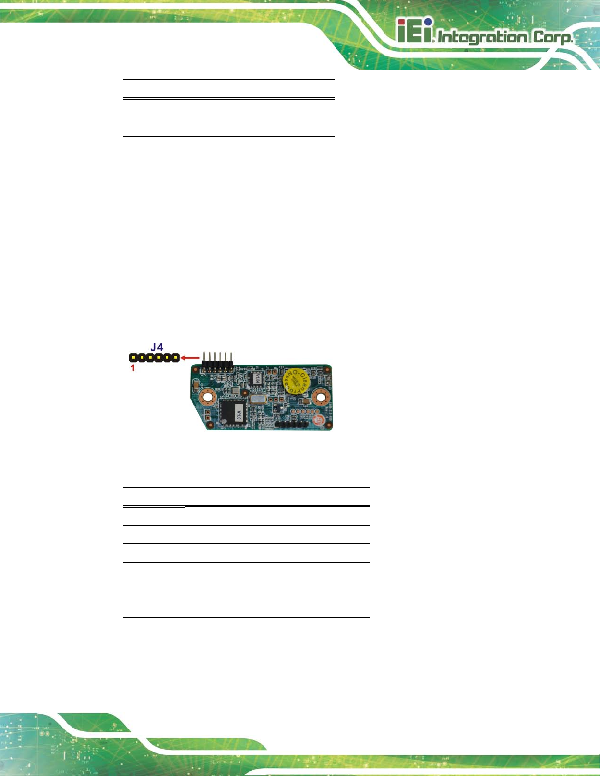
2.2.3 RS-232 and USB Connector
CN Label: J4
CN T y pe:
6-pin header
CN Location: See Figure 2-4
CN Pinouts: See Table 2-3
The 6-pin RS-232 and USB connector is connected to a RS-232 and USB Y cable.
Figure 2-4: RS-232 and USB Connector Location s
Pin No. Description
1 GND
2 USBDM
3 USBDP
4 +5V
5 RXD
6 TXD
Table 2-3: RS-232 and USB Connector Pinouts
Page 15

AFL2-EM-RFID-KIT01
Page 8
2.2.4 LED Indicators
CN Label: D1 and D2 (Solder Side)
CN T y pe:
There are two LED indicators located on the solder side of the AFL2-EM-RFID-KIT01
module to indicate the power status and activation status.
On-board LED
Page 16

AFL2-EM-RFID-KIT01
Page 9
Chapter
3
3 Unpacking
Page 17

AFL2-EM-RFID-KIT01
Page 10
3.1 Anti-static Precautions
WARNING!
Static electricity can destroy certain electronics. Make sure to follow the
ESD precautions to preve nt damage to the product, and injur y to the
user.
Electrostatic discharge (ESD) can cause serious damage to electronic components,
including the AFL2-EM-RFID-KIT01-R10. Dry c limates are es pecia lly susc epti ble to ESD.
It is therefore crit ical th at whene ver the AFL2-EM-RFID-KIT01-R10 or any other electrical
component is handled, the follo wing ant i-static precautions are strictly adhered to.
Wear an anti-static wristband: Wearing a simple anti-static wristband can
help to prevent ESD from damaging the board.
Self-grounding: Touch any grounded conducting material before handling
the board. During the time the board is handled, frequently touch any
conducting materials that are connected to the ground.
Use an anti-static pad: When configuring the AFL2-EM-RFID-KIT01-R10,
place it on an antic-static pad. This reduces the possibility of ESD damaging
the AFL2-EM-RFID-KIT01-R10.
3.2 Packing Lis t
NOTE:
If any of the components listed in the checklist below are missing, do not
proceed with the installation. Contact the IEI reseller or vendor the
AFL2-EM-RFID-KIT01-R10 was purchased from or contact an IEI sales
representative directl y by sending an email to
sales@iei.com.tw.
The AFL2-EM-RFID-KIT01-R10 is shipped with the following components:
 Loading...